3.1. Metal Shielding Work and Failure
Within a conductive material exposed to a time-varying magnetic field, eddy currents are induced. These circulating eddies of current have inductance and induce magnetic fields. These fields cancel the incident magnetic fields penetrating the material, and so the net magnetic field in the vicinity of the material is reduced [
14]. Obviously, the distribution of the eddy currents flowing in certain geometric configuration might be the key in the metal shielding effect and therefore needs to be researched.
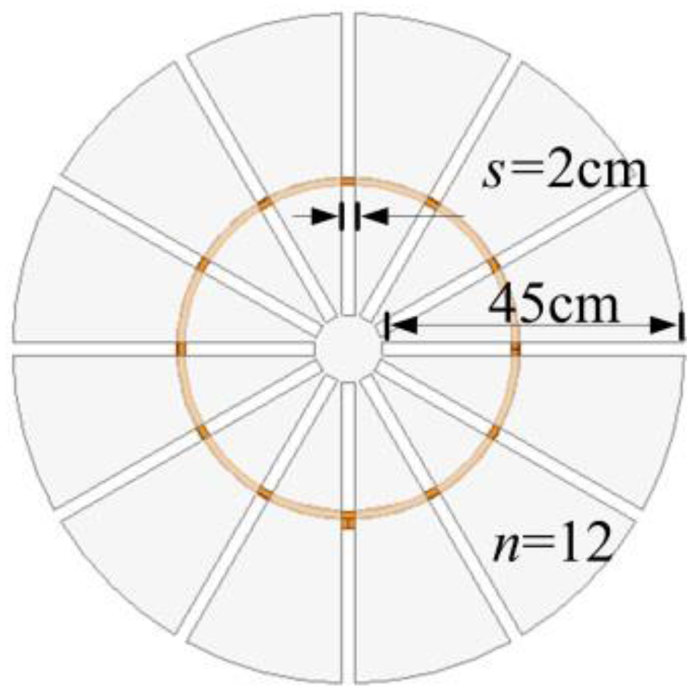
With the purpose of figuring out the eddy currents distribution in the metal, as well as the aim of achieving an optimized geometric configuration, we etch
n number of slots on both of the two aluminum sheets, as shown in
Figure 3, to study the change in eddy currents distribution with the metal geometric. All the slots are 45cm length from the edge to the center with
s width and 0.1 cm deep.
While
Po = 3 kW,
ω = 2 × π × 10
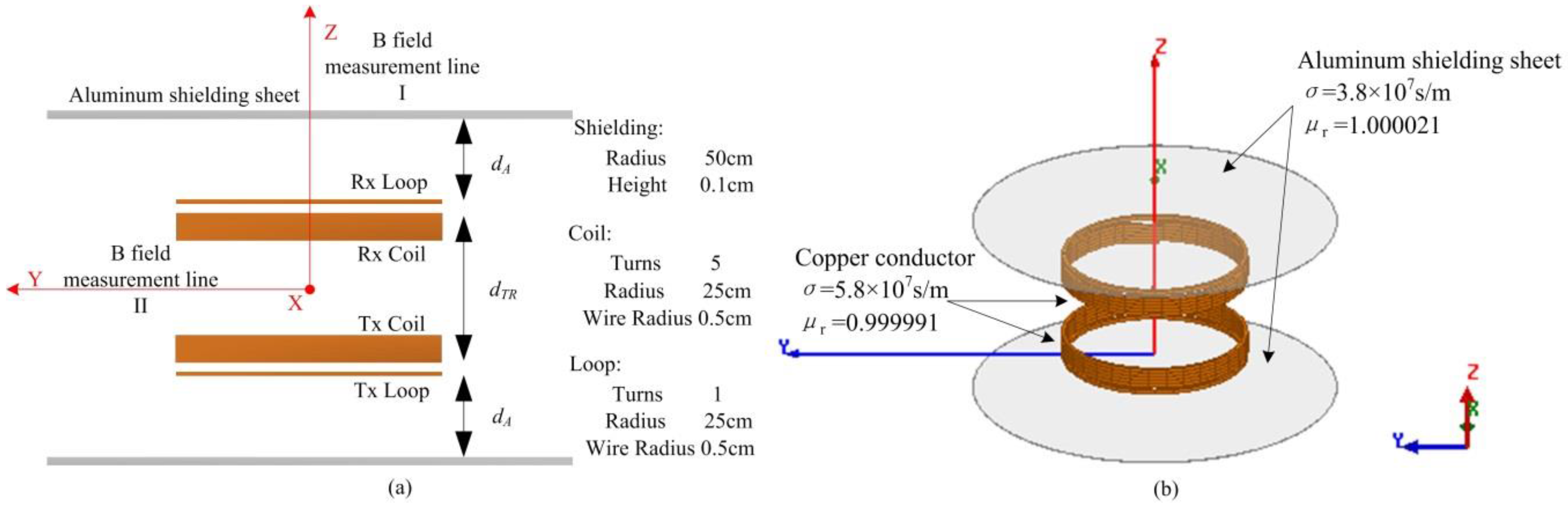
6 rad/s, and the variable values in
Figure 2 are substituted as
dTR = 60 cm,
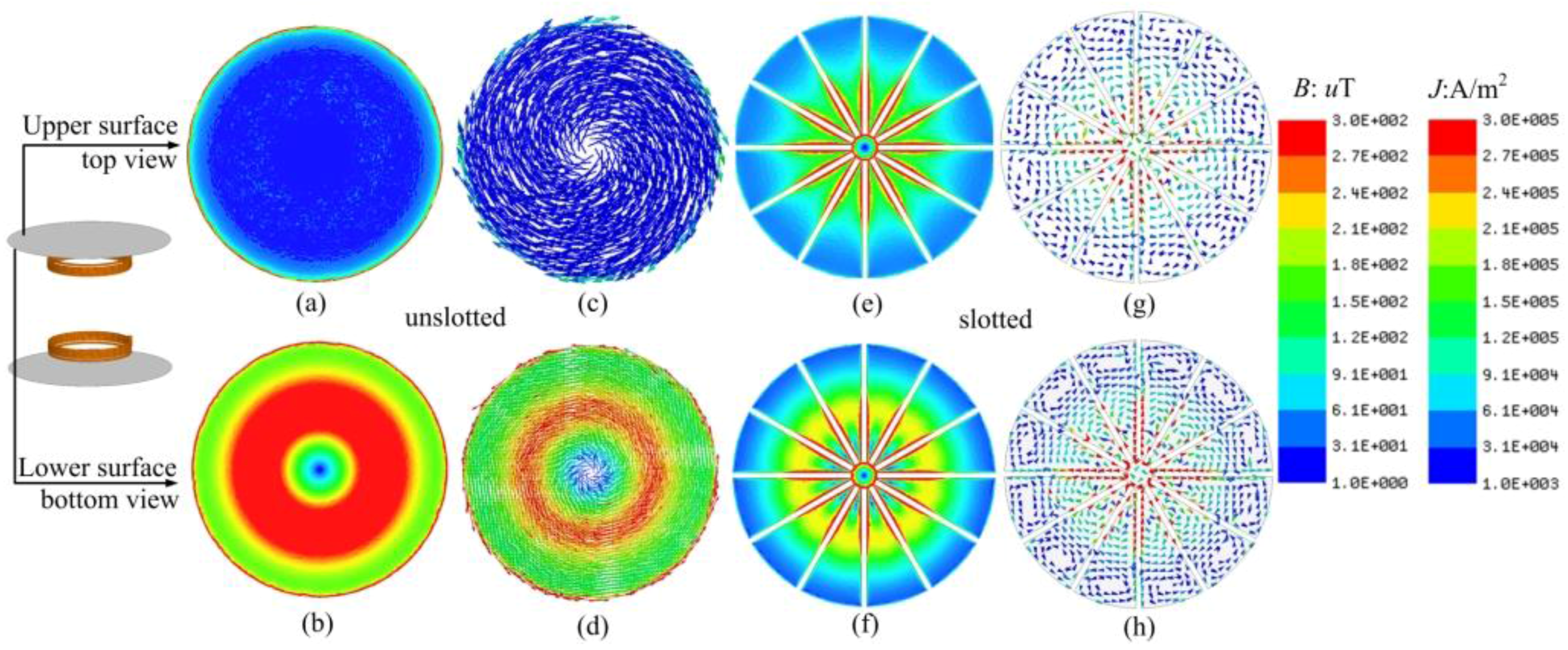
dA = 10 cm, the impedance matrix in Equation (1) can be obtained using ANSYS, the currents in the coils can be calculated using Equations (1) and (2) and the magnetic flux and eddy currents density on aluminum sheet above the Rx Loop are presented in
Figure 4.
Figure 4a, c show that the magnetic flux density and eddy currents density are weak on the upper surface of unslotted aluminum sheet. It can be observed from
Figure 4b, d that the magnetic flux density is high on the lower surface of the unslotted aluminum sheet edge and the region close to the coils, and the eddy currents also concentrate close to the high-intensity magnetic field region. The magnetic field and eddy currents distribution on the slotted aluminum sheet are presented in
Figure 4e–h where
n = 12 and
s = 2 cm. We can see that the slots cut through what were originally high-intensity magnetic field regions on the sheet where the eddy currents are supposed to be high. As a result, relatively stronger eddy currents flow along the edges of the slots on both the upper surface and the lower surface while the weaker currents flow on partitions segmented by slots. Although the eddy currents density
J A/m
2 is strong on the edges of the slots, total currents
I (A) won’t be high due to the weak eddy currents density on most of the area of the sheet. The eddy currents on unslotted sheet are much larger than that on the slotted sheet, as
Figure 4d,g,h show; thus the induced magnetic field by the eddy currents on the unslotted sheet is obviously stronger. The eddy currents’ redistribution leads to the variation in the magnetic field. By comparing the magnetic flux density on the upper surface in
Figure 4a,e, the unslotted sheet might show better shielding effectiveness. We can conclude that slots on the metallic sheets can distinctly change the eddy currents distribution, and the metallic sheets’ geometric configuration might be extremely relevant to its shielding effect.
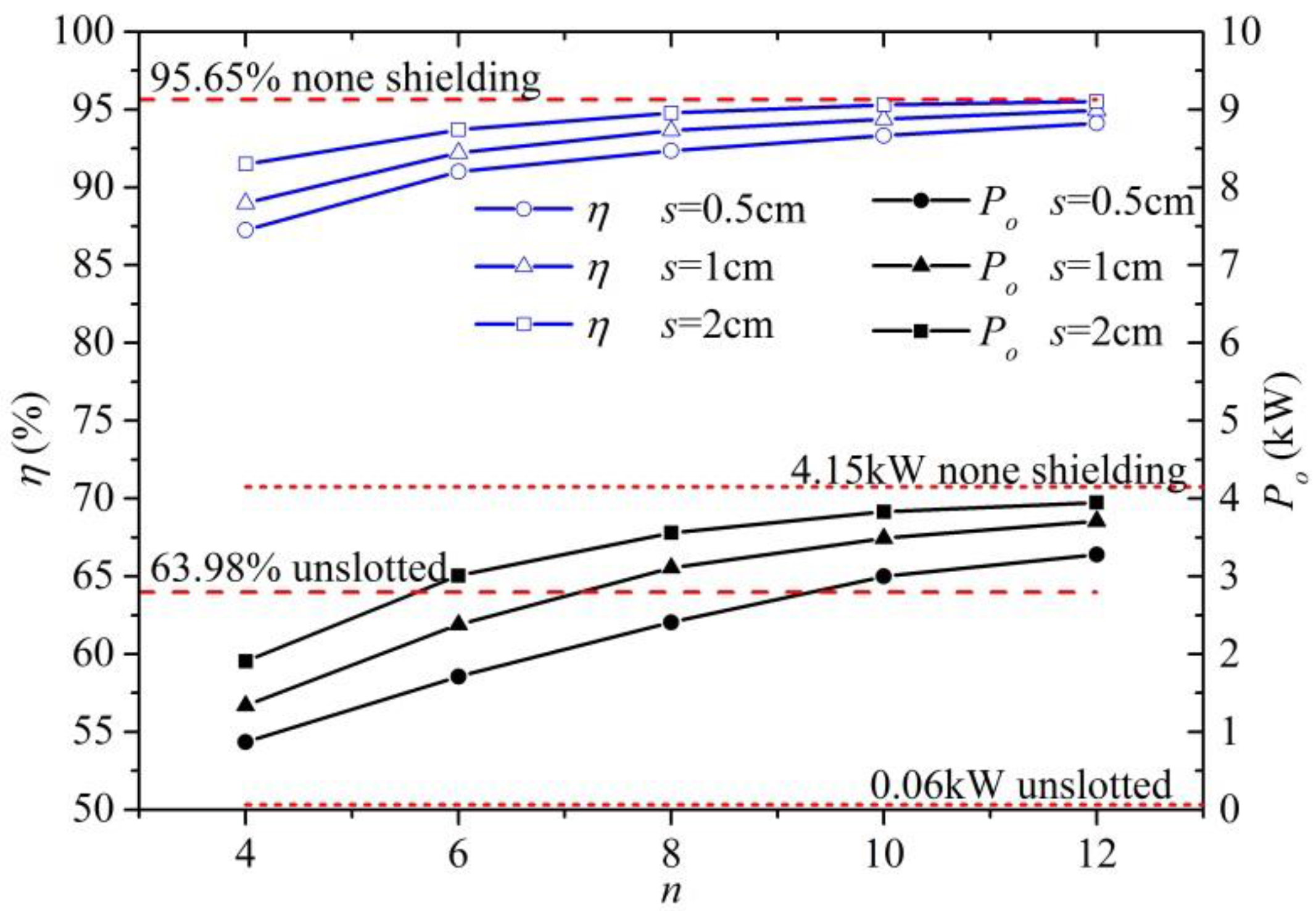
Various slots’ number
n and width
s are analyzed in
Figure 5 as the excitation voltage source
V1 = 1 kV. The impedance matrix of the WPT system with slotted aluminum sheets can be obtained by ANSYS. Using Equations (1), (2) and (4), the efficiency of system
η can be calculated as 95.65% with none shielding and 63.98% with unslotted aluminum sheets, the transmission power
Po 4.15 kW and 0.06 kW, respectively, with the increase of
n and
s,
η and
Po will increase close to none shielding condition on account of the decrease of eddy currents.
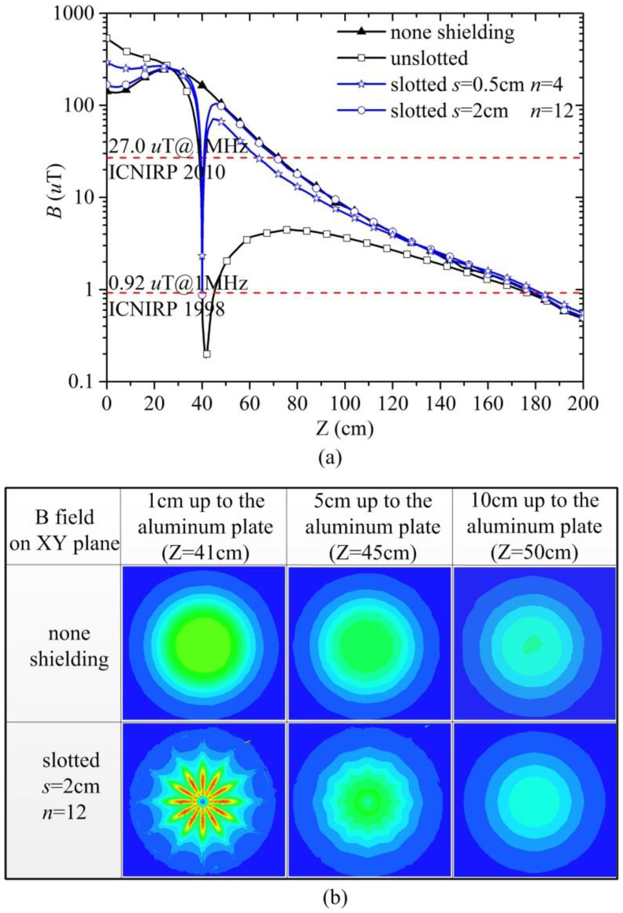
In order to compare the differences in the vertical magnetic flux density
Bv under the condition of constant transmission power
Po of 3 kW, the simulated results along the measure line I are shown in
Figure 6a with human exposure limits published by the International Committee on Non-Ionizing Radiation Protection (ICNIRP) [
15,
16]. The graphed contours shown in
Figure 6a clearly illustrate the differences in each magnetic flux density distribution. In particular, the unslotted aluminum sheets significantly shield the magnetic field in a wide range away from Z = 40 cm where the upper aluminum sheet locates while the slotted one can only reduce the magnetic flux density within an extremely narrow range close to the aluminum sheet, and more slots will lead to a weaker shielding effect.
Figure 6b shows the differences of magnetic field distribution on XY plane with various Z values between the none shielding condition and the slotted one. The eddy currents on the slotted sheet will strengthen magnetic field in the immediate vicinity to the slots, the magnetic field distribution approximates to a none shielding condition and the slotted sheet shows little shielding effect beyond a small distance due to the weak total eddy currents on the slotted sheet.
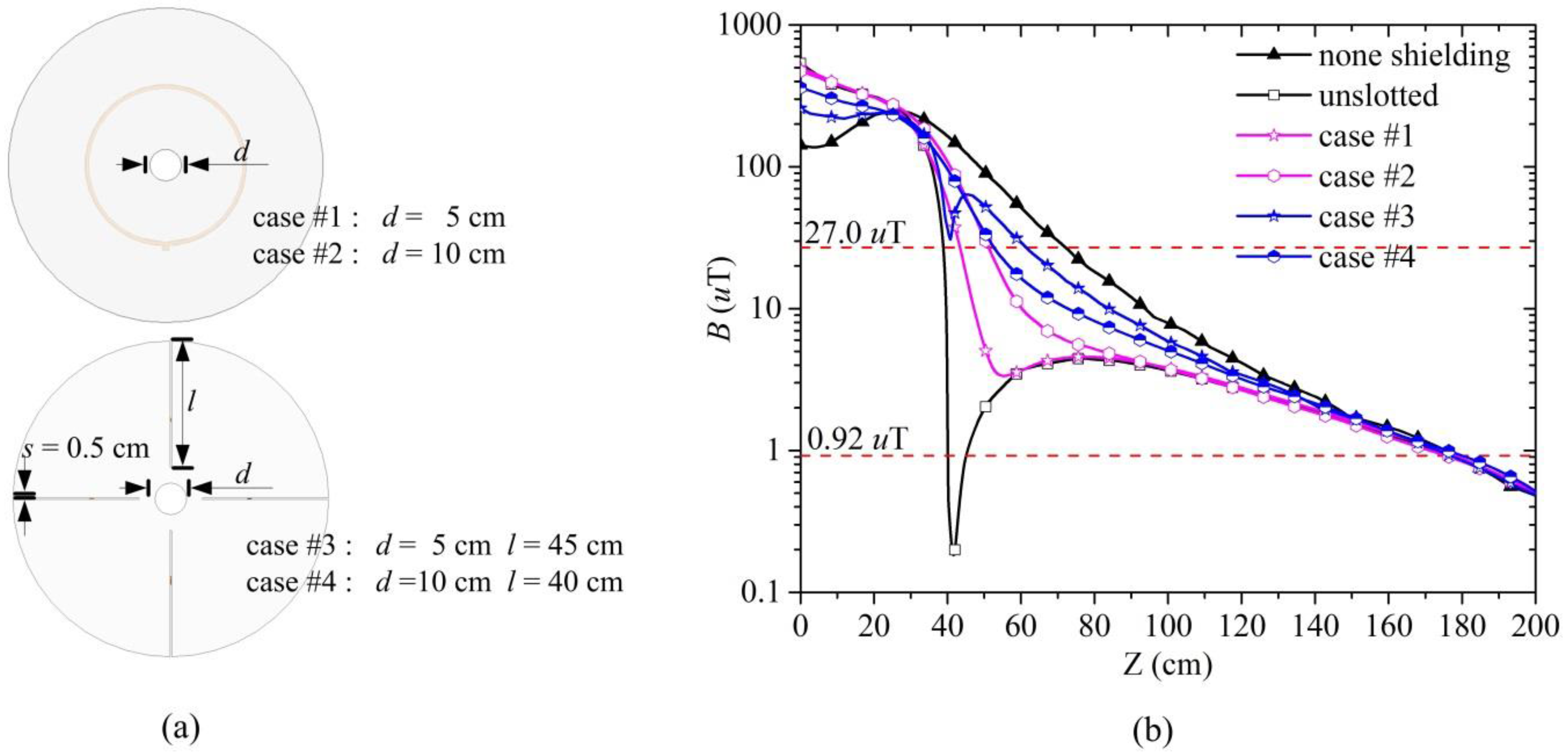
According to the above conclusion, the aluminum sheet with the slots cutting through what were originally high-intensity magnetic field regions on the sheet shows a much weaker shielding effect, whereas slots in low-intensity magnetic field regions are expected to be more effective. In
Figure 4b, the weak magnetic field region distributes on the center-micro-area of the sheet, so we etch this region totally as
Figure 7a shows. The diameter of the circular aperture
d equals 5 cm for case #1 and 10 cm for case #2. Although not as good as the unslotted condition, both the two cases show better shielding effects than the slotted ones, which can be observed by comparing the magenta curves in
Figure 7b and the blues curves in
Figure 6a. The shielding effect will also decline with the increase of the circular aperture size as the high-intensity magnetic field region is etched; to improve it close to the unslotted condition, the circular aperture size should be diminished. Case #3 and case #4 are aluminum sheets with circular apertures and slots. The diameter of the aperture
d is 5 cm for case #3 and 10 cm for case #4, the slots length
l is 45 cm for case #3 and 40 cm for case #4. As the slots in case #3 and case #4 cut through high-intensity magnetic field regions on the sheet, the shielding effect is weakened. The efficiency of the four cases is 64.62%, 69.73%, 86.43%, and 73.16%, respectively. According to the four cases, we can conclude that better transfer efficiency is always obtained with a worse shielding effect due to the influence of eddy currents. Although the aperture size of case #4 is larger than that of case #3, case #4 shows better shielding effectiveness because of the shorter slots in high-intensity magnetic field regions. The results indicate that both the slots and aperture should be etched in weak magnetic field regions, otherwise they will lead to drastic declines in the shielding effect.
In summary, slots etched in the metals can alter the eddy currents path, and reduce adverse impacts on the electrical performance of a WPT system, but they might also lead to a shielding performance reduction or shielding failure. Hence, guaranteeing the integrity of the metallic sheets’ geometric configuration, especially the edge and high-intensity magnetic field regions, is the key feature the metallic sheets should satisfy for demonstrating shielding effects. In addition, for the sake of achieving light-weight, economical, and small-size shielding geometric configurations within acceptable declines in the shielding effect, the metal sheets can be etched in the weak magnetic field region which varies with specific cases.
3.2. Metal Shielding Effect Contrast
In order to use metals for the suppression of magnetic field leakages from a WPT system, their effects on the electrical performance of a WPT system should be considered. The metals in the vicinity of the coils cause the decrease of self and mutual inductances and the increase of effective series resistance, as Equation (1) shows. By placing two metallic sheets symmetrically outside the Tx Loop and Rx Loop, the magnetic field can be well confined between two metallic plates, thus improving magnetic flux focusing, and the transfer efficiency of the system is also further improved [
9,
17]. However, this approach is often restricted by the size, structure, and variable coupling conditions, and the transmission power is also not high enough in a metal shielded environment [
13]. Hence, research should be carried out on the metal shielding effect together with the electrical performance, including the transmission power and the efficiency of the WPT system. As the previous section shows, the vertical magnetic flux density can be shielded effectively by aluminum sheets, however, the horizontal magnetic flux density must be studied to achieve the optimal shielding scheme. Since the sheets used in this study are already of a suitable size, the weak magnetic field region on the sheet is so small; as such, it makes little sense to etch slots in the micro-region considering the decline in shielding effect. Thus, the geometric entirely unbroken metallic sheets are adopted for further research for purposes of simplicity.
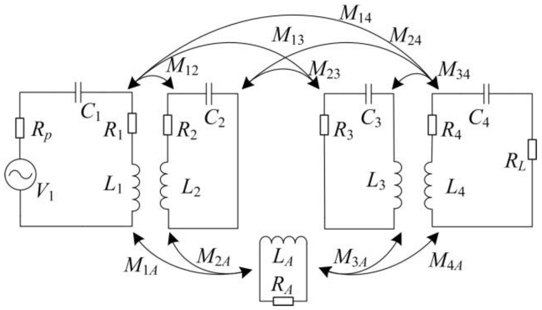
According to the impedance matrix in Equation (1), we define the coupling coefficient of the Tx and Rx Coils in consideration of the metal effects as
The critical coupling coefficient [
18] without considering the metal effects can be calculated using
The critical coupling coefficient of the WPT coils in
Figure 2 equals 0.056 using Equation (6) with the parameters in
Table 1. Different values of
dTR and
dA are set to the research variable coupling conditions of the WPT coils. Coupling coefficient
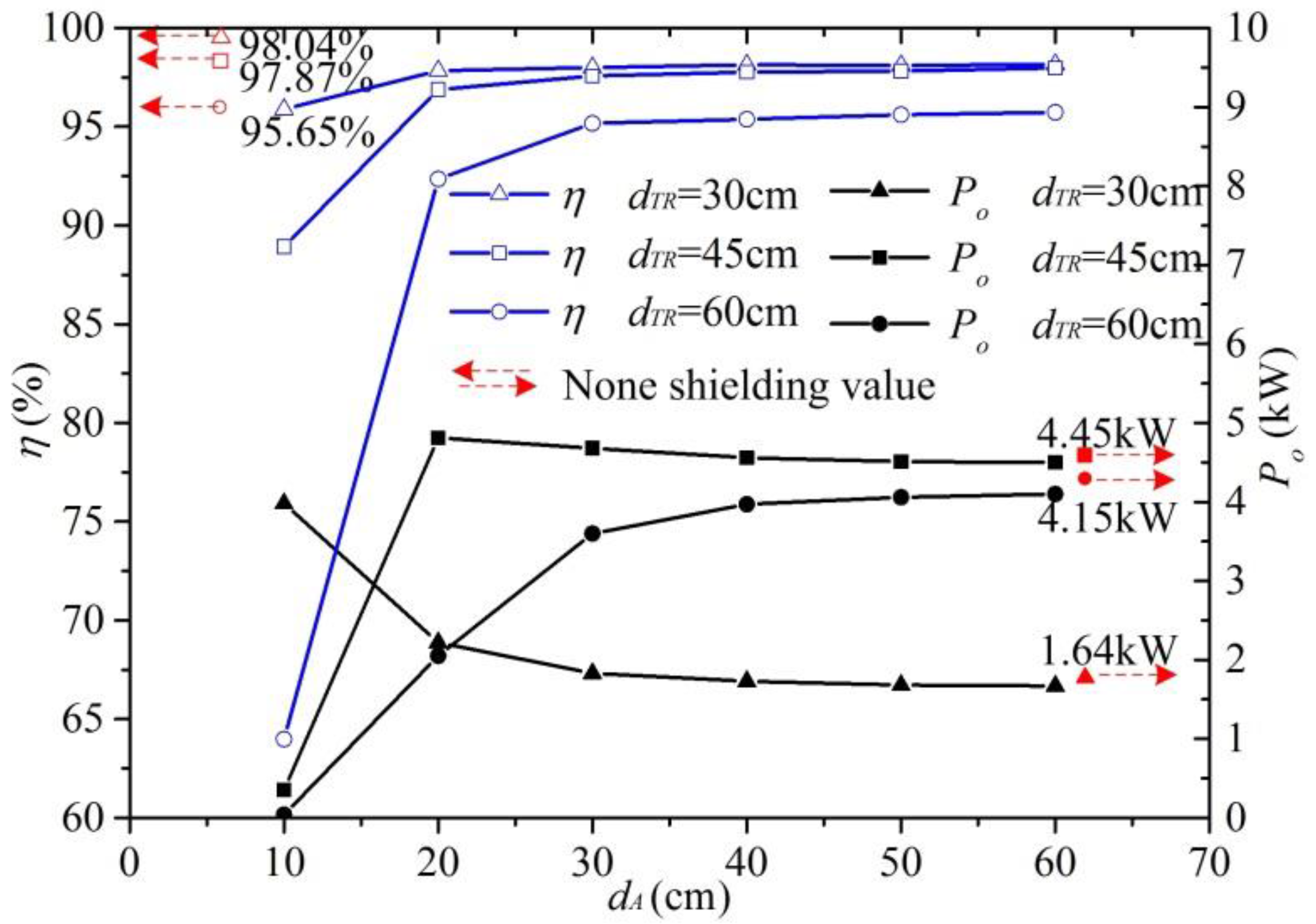
k23A is shown in
Table 2, the results of
η and
Po as
V1 = 1 kV,
ω = 2 × π × 10
6 rad/s are shown in
Figure 8. The values in
Table 2 indicate that the coupling coefficient of the Tx and Rx Coils in consideration of the metal effects
k23A will increase close to none shielding value
k23 with the increase of the sheets distance
dA.
As the curves in
Figure 8 show, when
dTR = 30 cm (
k23 = 0.173),
Po = 1.64 kW, and
η = 98.04%, as
dA increases from 10 cm to 60 cm,
Po decreases from 3.98 kW to 1.67 kW, and
η increases from 95.89% to 98.16%; when
dTR = 45 cm (
k23 = 0.075),
Po = 4.45 kW and
η = 97.87%; as
dA = 10 cm,
Po = 0.35 kW and
η = 88.92%; as
dA = 20 cm,
Po = 4.81 kW and
η = 96.88%; as
dA increases to 60 cm,
Po decreases to 4.50 kW and
η increases to 97.98%; when
dTR = 60 cm (
k23 = 0.037),
Po = 4.15 kW,
η = 95.65%, as
dA increases from 10 cm to 60 cm,
Po increases from 0.06 kW to 4.10 kW and
η increases from 63.98% to 95.73%.
We can summarize from
Table 2 and
Figure 8:
The coupling coefficient of the coils changes based upon the metallic sheets in the vicinity and the transmission power Po reaches peak as the coupling coefficient of the coils (k23, k23A) approaches the critical coupling coefficient kc;
Po decreases to a stable value gradually with the increase of k23A when k23A > kc; Po decreases to zero rapidly with the decrease of k23A when k23A < kc;
The efficiency of system η increases with k23A and has a slight improvement against the none shielding condition when k23A is large; η decreases drastically when k23A is small.
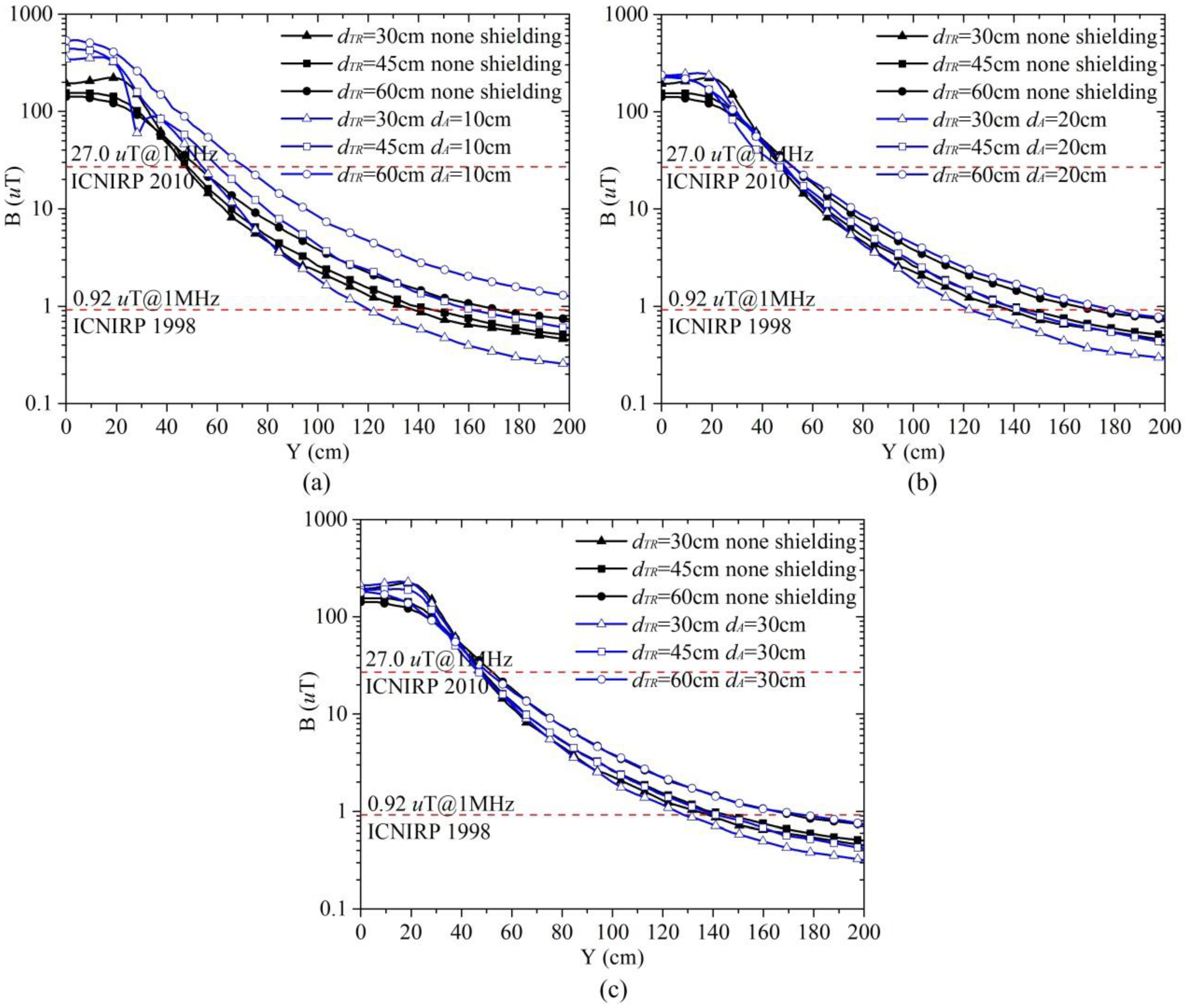
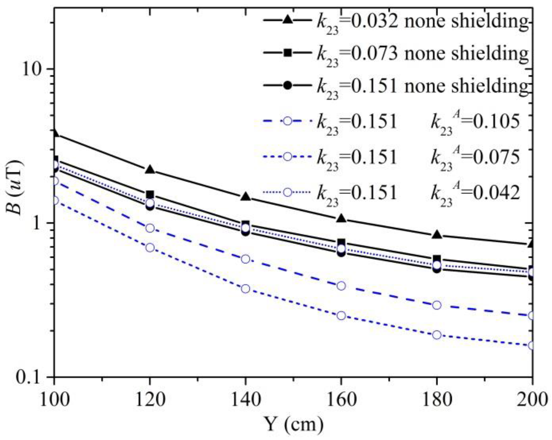
The horizontal magnetic flux density
Bh under the condition of constant transmission power
Po of 3 kW along the measure line II is shown in
Figure 9.
In the range 100 cm ≤ Y ≤ 200 cm, none shielding curves in
Figure 9 show
By contrasting the aluminum shielding and none shielding curves in
Figure 9a–c, respectively, we can get
By comparing curves in
Figure 9, we can also get
where Δ
B is the difference in value of the magnetic flux density between the aluminum shielding condition and none shielding condition. In
Figure 9, the safe region meeting the ICNIRP 1998 guidelines is largest as
dTR = 30 cm and
dA = 10 cm.
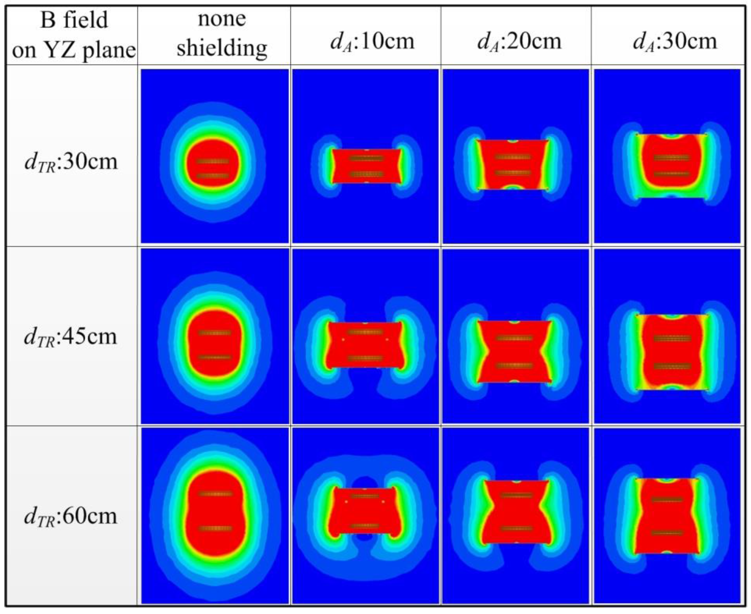
Figure 10 shows the magnetic field distribution on a YZ plane under various coupling conditions.
We can reach the following conclusions from
Figure 9 and
Figure 10:
Metallic sheets can shield the vertical magnetic field well, but are relatively weak at shielding the horizontal magnetic field;
In the condition of none metal shielding and constant transmission power Po, the larger the coupling coefficient of the coils k23 is, the weaker the horizontal magnetic field will be. Bh increases rapidly with the decrease of k23 when k23 < kc, and decreases slowly with the increase of k23 when k23 > kc;
In the metal shielding condition, the horizontal magnetic field is stronger than the none shielding condition when k23A < kc. The metallic sheets show no shielding effect; this is because the metallic sheets in the vicinity of the coils under a low coupling coefficient will seriously affect the transmission characteristics of the WPT system, and therefore more input current is needed to keep the transmission power constantly. The smaller k23A is, the larger the Bh increment will be—the increment decreases with the increase of k23A. As k23A > kc, the increment is negative, the horizontal magnetic field is weaker than the none shielding condition, and the metallic sheets show a shielding effect. The smaller k23A is, the larger Bh decrement will be.
Given the above, the metallic sheets can achieve the best shielding effect by increasing the coupling coefficient of the coils k23 as large as possible within the allowable range and by utilizing the metal effects to make k23A nearest to and no smaller than kc: k23A − kc → 0+.


