1. Introduction
Wind power generation, as the most competitive and clean renewable energy technology, is attracting more and more attention all over the world. In wind energy conversion systems, permanent magnet generators (PMGs) have been widely used for their numerous advantages such as simple structure, high efficiency, reliable operation and no need for an additional power supply due to the magnet field excitation. Most PMGs contain rare-earth permanent magnet materials, namely, NdFeB grades, for their high remanence and coercivity values [
1,
2,
3,
4,
5]. However, the cost of NdFeB magnets has increased significantly over the last several years and there is an increasing concern about the stable supply of the raw material for NdFeB [
6]. With this consideration, generators with less or without rare-earth materials are required in wind power applications to reduce the machinery cost [
7].
Ferrite magnet material has many merits, such as low weight density, low cost, and stainless nature, etc. PMGs using ferrite magnets were studied in [
8,
9,
10]. Due to the relatively low residual flux density of ferrite magnet material, it is obvious that the performance is dramatically decreased when a ferrite magnet with 0.4 T of remanence is used instead of a NdFeB magnet [
11]. In order to resolve this problem, the dual rotor permanent magnet (PM) machine using ferrite magnets was proposed [
12]. When using NdFeB magnets, the dual rotor permanent magnet (DRPM) machine can significantly improve the torque density and efficiency owing to the special structure of double rotors and dual air-gaps. In fact, the improvement of torque density is achieved by doubling the working portion of the air gap [
13,
14]. Accordingly, the torque density and efficiency of the DRPM wind generator using ferrite magnets are higher than those of traditional PM generators using ferrite magnets. Qu designed a dual rotor permanent magnet (DRPM) motor using ferrite magnets in [
15]. In [
16] he came to the conclusion that the torque density of a DRPM is almost three times the density of a commercial induction motor (IM) and 2.2 times the density of a commercial interior PM (IPM) machine with an efficiency just slightly lower than that of an IPM machine, but higher than that of an IM. Hence, we may consider transplanting the dual rotor machine using ferrite to wind power generation.
DRPM machines include dual rotor radial flux PM machines and dual rotor axial flux PM machines [
17]. In general, dual rotor radial flux (DRRF) and dual rotor axial flux (DRAF) machines have similar torque density, torque-to-mass ratio, losses, and efficiency performance. However, the material cost of DRAF machines is much higher than that of DRRF machines due to more magnets being required for DRAF machines. Meanwhile, the DRRF machines need and can provide stronger cooling capability than DRAF machines [
18]. As a consequence, this paper proposes a DRRF wind generator using ferrite magnets.
When performing preliminary design of an electric machine, the equivalent magnetic circuit (EMC) approach is a popular choice for designers due to its fast and analytical nature [
19]. EMC needs empirical coefficients to correct the magnetic saturation and leakage flux conditions. Those coefficients are easily affected by many factors, including the operation state and magnetic saturation level, so the precision of the EMC approach is not high enough to use in practice. The finite element method (FEM), as a numerical method, is a numerically accurate algorithm [
20], but is too time-consuming. Considering the fast performance of EMC and high accuracy of FEM, the analytical approach combining EMC and FEM should be a good compromise between simplicity and accuracy. This approach is useful and effective in the preliminary design of an electrical machine.
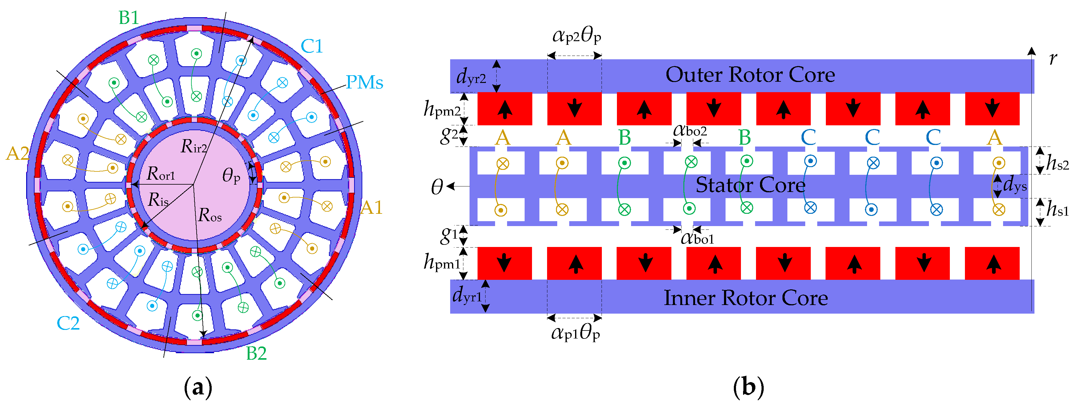
The main contribution of this paper is the development of a comprehensive analytical model for a DRRF wind generator based on EMC. The elements of this analytical model are precisely calculated in cylindrical coordinates to achieve a high accuracy. The proposed model takes into account the iron saturation, all generator dimensions as well as material properties, and is able to accurately predict the electromotive force (EMF), torque and cogging torque, as well as numerous other design aspects. The results of the proposed model are then evaluated and verified by FEM. The errors between the proposed model and FEM model are less than 5% for flux densities, 3% for EMF, and even as low as 1% for electromagnetic torque, which are basic parameters used to verify the feasibility of the proposed model. In addition, the working points at different temperatures are measured to determine whether the ferrite magnets are demagnetized or not, and the corresponding results indicate that irreversible demagnetization does not occur.
At the end of this paper, the optimization to achieve specific design objectives, such as making the best use of the inner space of the DRRF generator, decreasing the cogging torque, and reducing the total harmonic distribution (THD) of the back EMF, is presented. Consequently, the optimal split ratio of the inner and outer stator radius, the pole arc ratio of the inner and outer rotors, and the outer slot opening are determined.
3. Model Evaluation
In this section, characteristics of the DRRF wind generator are obtained and evaluated by the proposed analytical model and are compared with those extracted from FEM. The FEM analysis is an auxiliary approach to validate the analytical model, slightly adjust it, and prove its predictions. The primary design specifications and parameters are given in
Table 1.
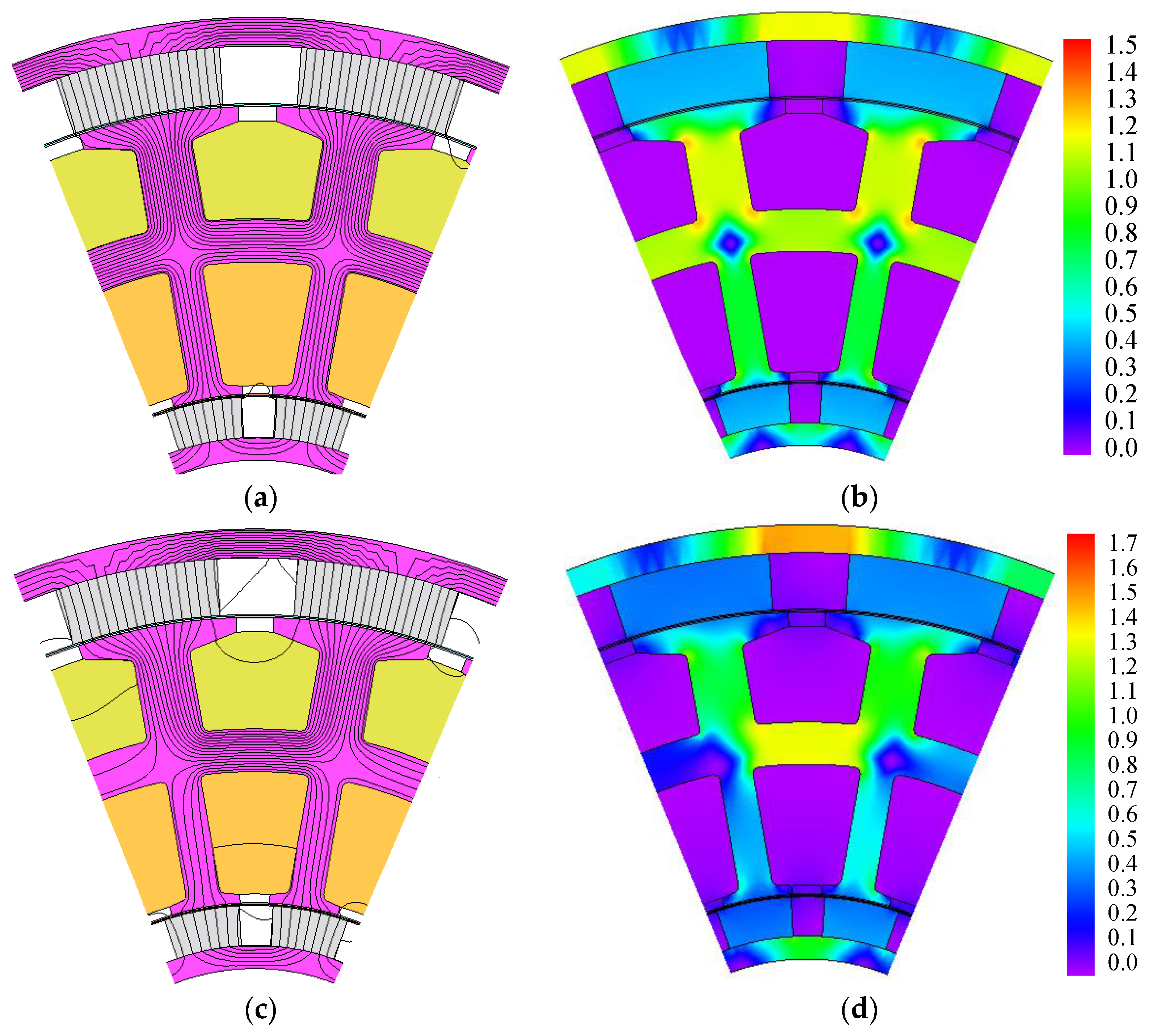
Flux line distribution and flux density distribution for both no load and full load conditions are illustrated in
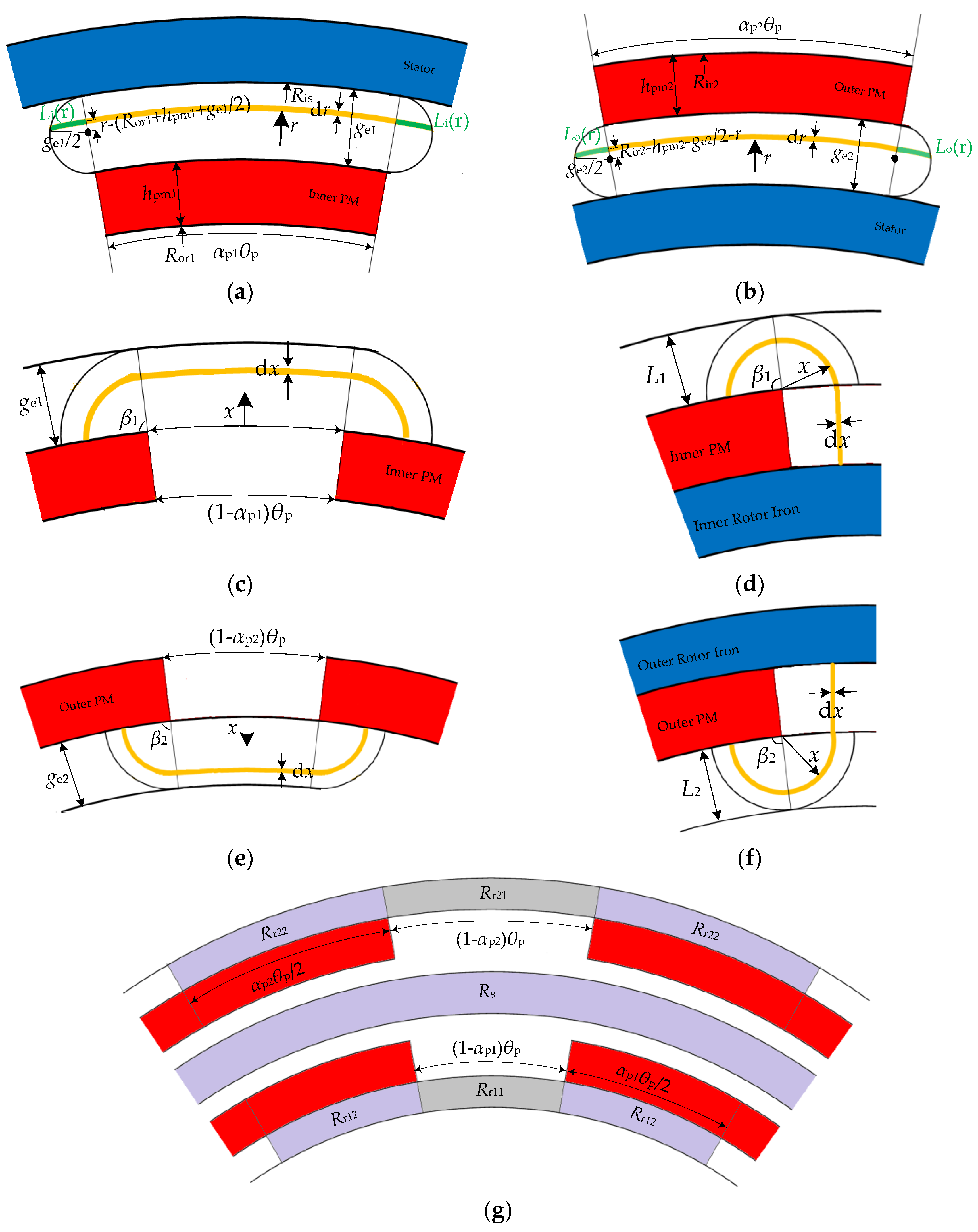
Figure 6. It can be found that the flux densities within the portions corresponding to
Rr11 and
Rr21 are higher than those corresponding to
Rr12 and
Rr22, which verifies the correctness of the analysis result in
Figure 3g. By making a comparison between the distributions at no load and full load conditions, it can be seen that some distortions in the flux lines and flux density have appeared for the sake of the armature reaction.
The comparison shown in
Table 2 demonstrates that all the designed parameters closely agree to the FEM measurement values, and the errors between them are less than 5%. This implies that the model derived in
Section 2 is acceptable as a predictor of machine performance.
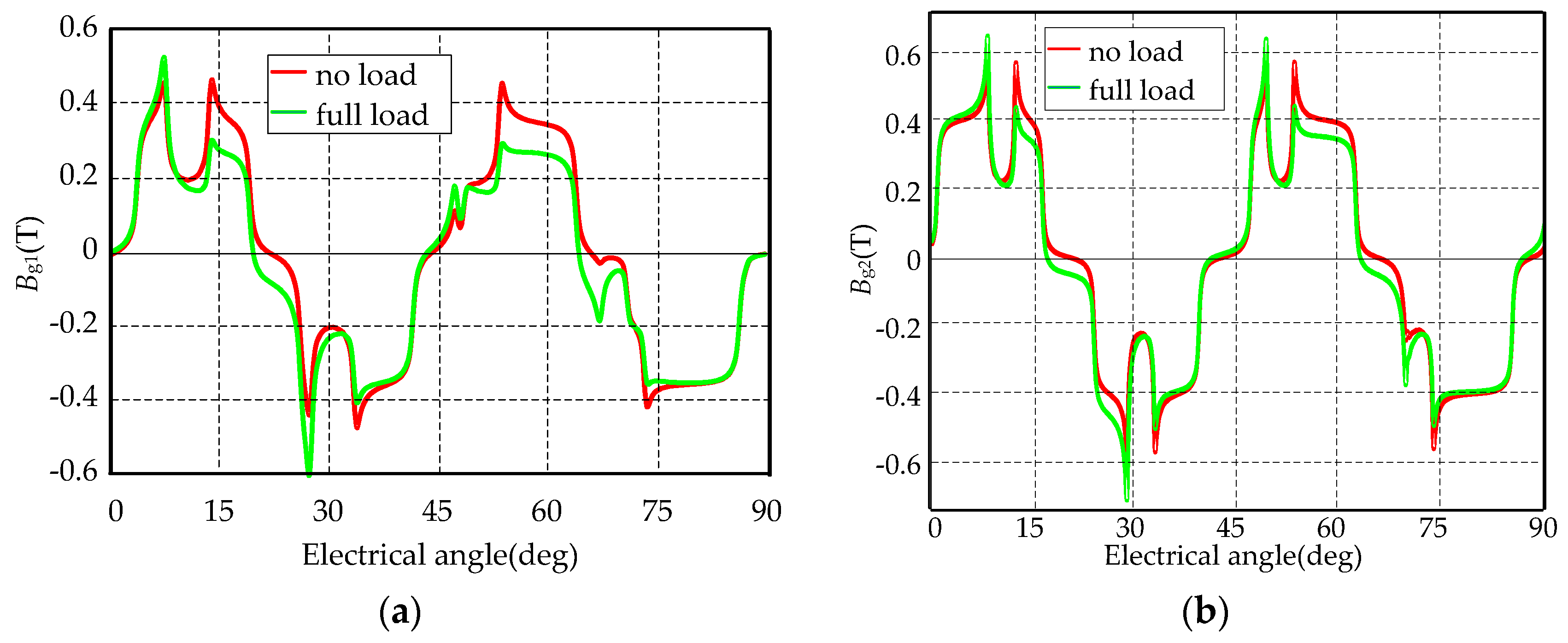
For the no load case, the magnetic fields in the inner and outer air gaps are all generated by ferrite magnets. However, for the load case, the magnetic fields are produced not only by the ferrite magnets but also the armature current. The armature current tends to create a magnetic field with its axis 90° away from the magnetic axis, which is called armature reaction. The effect of armature reaction field is to vary the amplitude and phase of the magnetic field in the air gaps.
Figure 7 shows how flux densities in the inner and outer air gaps are altered by the armature current. By comparison, the flux densities decrease in the one side of magnets while increase in the other side when the generator operates at full load. Due to the low remanence of the ferrite magnet material and the thickness of magnets, the effect of armature reaction is not very severe.
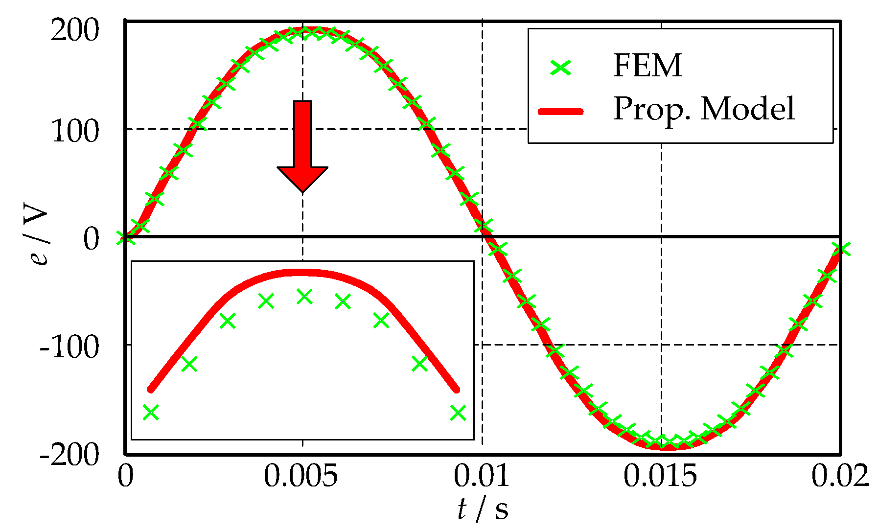
The developed back EMF of the proposed DRRF wind generator at the rated speed of 375 rpm is shown in
Figure 8. The results are still pretty close to each other, and the maximum discrepancy between them is less than 3%. As shown in
Figure 8, the waveform of the EMF is nearly sinusoidal and the THD is about 2.4%. The peak value obtained by the analytical model is about 185 V, which is slightly larger than the design value.
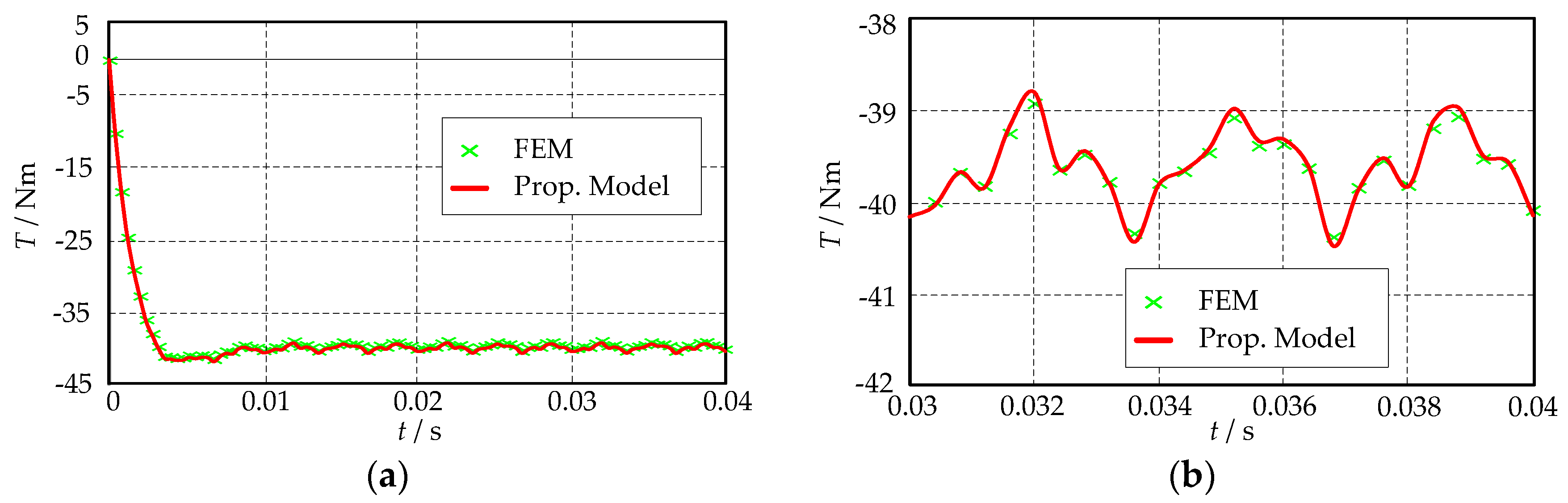
The electromagnetic torque and its pulsating torques of the DRRF wind generator at full load are exhibited in
Figure 9. The average value of the electromagnetic torque calculated by FEM is −39.6 Nm and that obtained by the analytical model is −39.7 Nm, which are very close to each other. As shown in
Figure 9b, there are pulsating torques in the electromagnetic torque. One of them is the cogging torque, and the other is the ripple torque produced by the interaction of the harmonic components of the flux densities in both air gaps and the sinusoidal current in the DRRF generator. The torque ripple (the difference between maximum value and minimum value) of the electromagnetic torque is 3.69%.
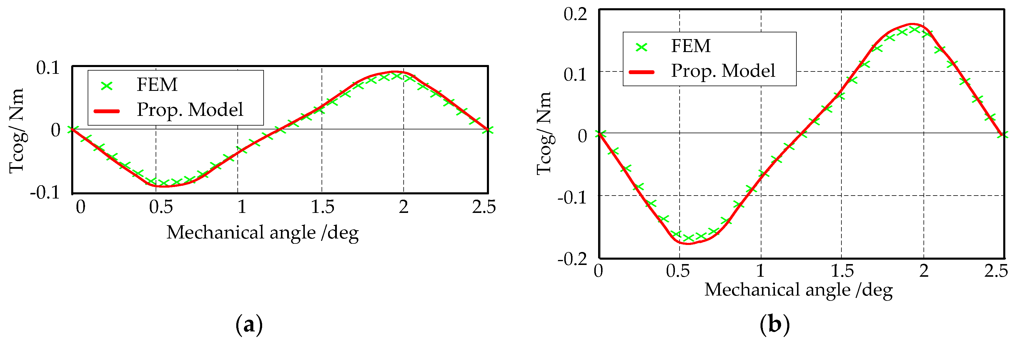
When the inner and outer parts of the DRRF wind generator are designed with the same slot opening angle and pole arc ratio, the cogging torques produced by the inner and outer air gaps will be in phase, as shown in
Figure 10, and the total cogging torque is their sum. According to Equation (60), the spatial period of the cogging torque is 2.5°. It can be seen that the cogging torque is satisfyingly low, since the wind turbine may never start with high cogging torque.
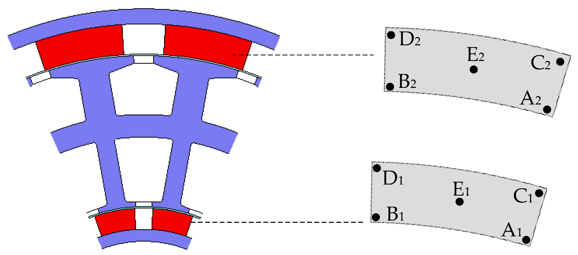
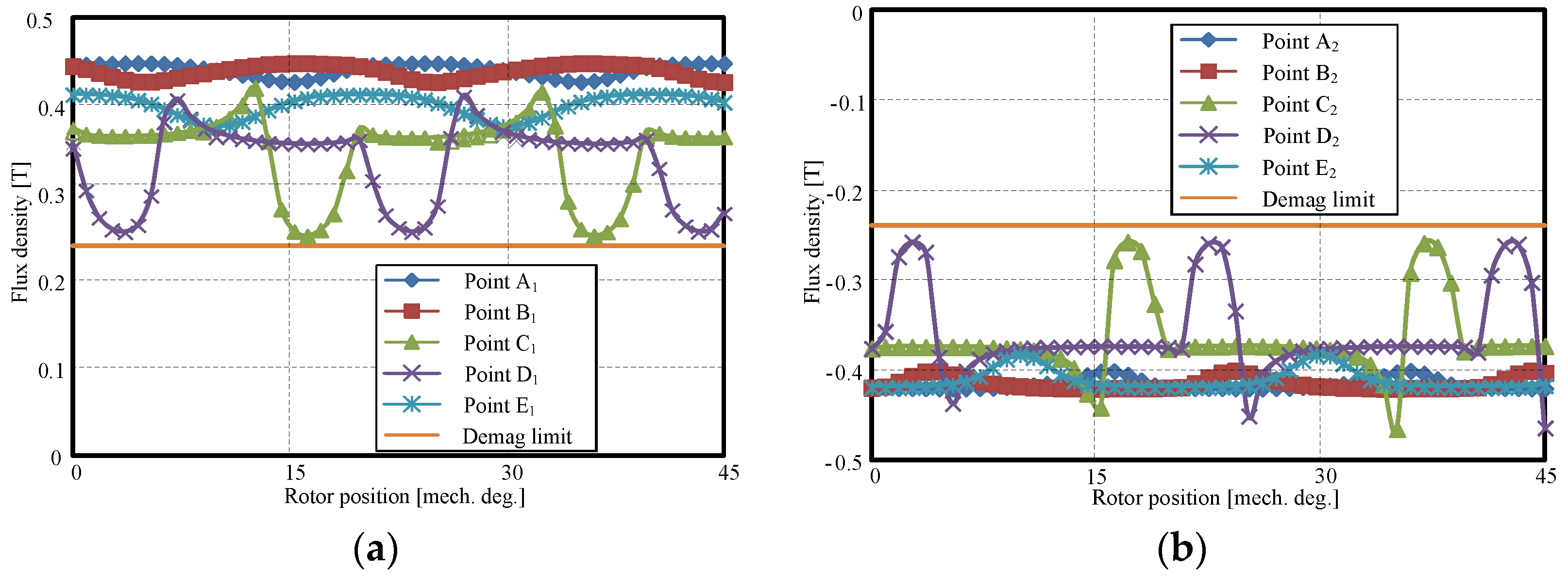
Since the ferrite magnet is vulnerable to demagnetization, this risk is estimated by calculating the flux density of ferrite magnets. To analyze the irreversible demagnetization characteristics, five different measuring points in the inner and outer magnets are chosen respectively as shown in
Figure 11. The flux densities of these points under no load operation at −20 °C in radial direction, which are the magnetization direction of the ferrite magnets, are shown in
Figure 12. It can be seen that the flux density of point C
1 is closer to the demagnetization limit value than other points. This means that point C
1 is easier to be demagnetized. So point C
1 is selected to confirm the working points at different temperatures, and the working points are shown in
Figure 13. The FEM results demonstrate that the DRRF wind generator is safe at all temperatures even at −20 °C.
4. Optimization by Finite Element Method (FEM)
A set of equations describing the generator performance are derived in
Section 2 and their validity are proven by FEM in
Section 3. However, designing a satisfying DRRF wind generator still needs optimization of some design parameters.
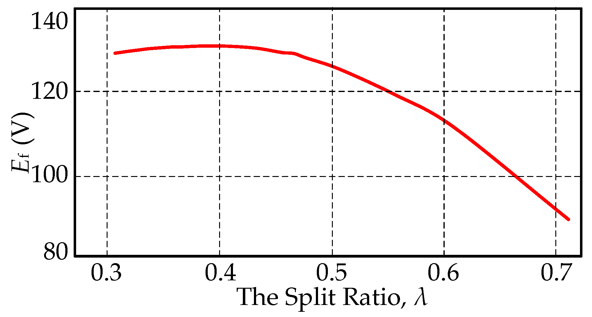
Due to the adoption of back-to-back toroidally wound winding, in order to take full advantage of the inner space, the area of the inner slot should equal to that of the outer slot. According to (46), we define the split ratio as λ =
Ris/
Ros, and then:
How λ affects
Ef is shown in
Figure 14, where it can be found that when λ is 0.43,
Ef reaches the maximum value. The reason is given as follows: on the one hand, the smaller λ is, the larger the whole area of the inner and outer slots is, so there are more conductors for producing induced voltage. On the other hand, the smaller λ is, the smaller
Ris is, and consequently there is less amount of magnet for producing induced voltage.
Torque ripple can generate acoustic noise, vibrations and mechanical stress in the wind turbine, thus, its minimization is highly required for wind power generations. Furthermore, the cogging torque caused by the tooth-slot structures, as an important component of the pulsating torque, must be minimized to better start wind power generator. There are several solutions to reduce the cogging torque, such as shifting the slot opening, shaping the magnets, skewing the stator or the magnets, varying slot opening angular width, and varying the pole arc ratio etc. By way of reducing manufacture cost, pole arc ratio design and shifting the slot opening are adopted to reduce the cogging torque.
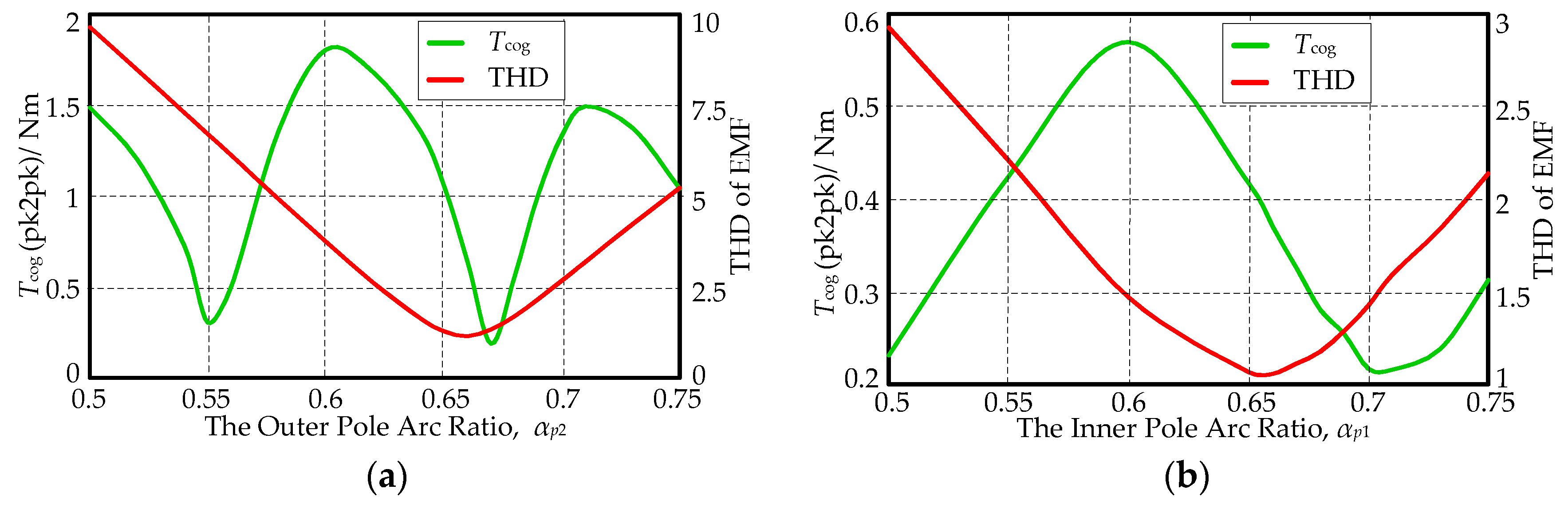
Since the energy stored in the outer air gap is more than that in the inner air gap, the total cogging torque of the DRRF generator is dominated by the outer portion. Therefore, the outer pole arc ratio α
p2 is firstly optimized and then the inner ratio
αp1 is secondly optimized. In fact, the pole arc ratio affects not only the cogging torque but also the THD of EMF. For the DRRF generator, how different
αp1 and
αp2 affect the cogging torque (peak-to-peak value, pk2pk) and THD of EMF is shown in
Figure 15. To obtain a sinusoidal-induced voltage with low cogging torque, compromise selection of parameters is considered. With this consideration, the optimal value of
αp2 is 0.67, and
αp1 is 0.69.
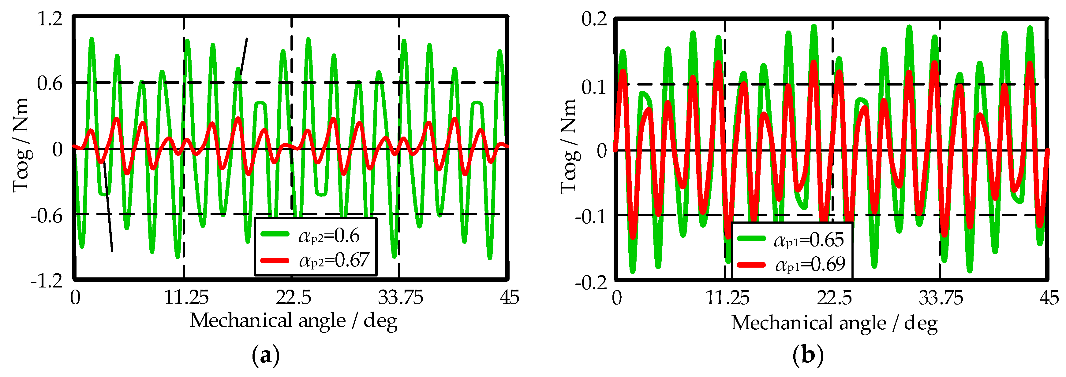
The cogging torque waveforms related to different pole arc ratios are demonstrated in
Figure 16. It is shown that the maximum value of cogging torque is significantly reduced by optimizing the outer pole arc ratio α
p2. The inner pole arc ratio α
p1 is also very important in this optimization. In this example, when α
p2 = 0.67 and α
p1 = 0.65, the maximum value of cogging torque reduces to 40% compared to that with α
p2 = 0.67 and α
p1 = 0.69.
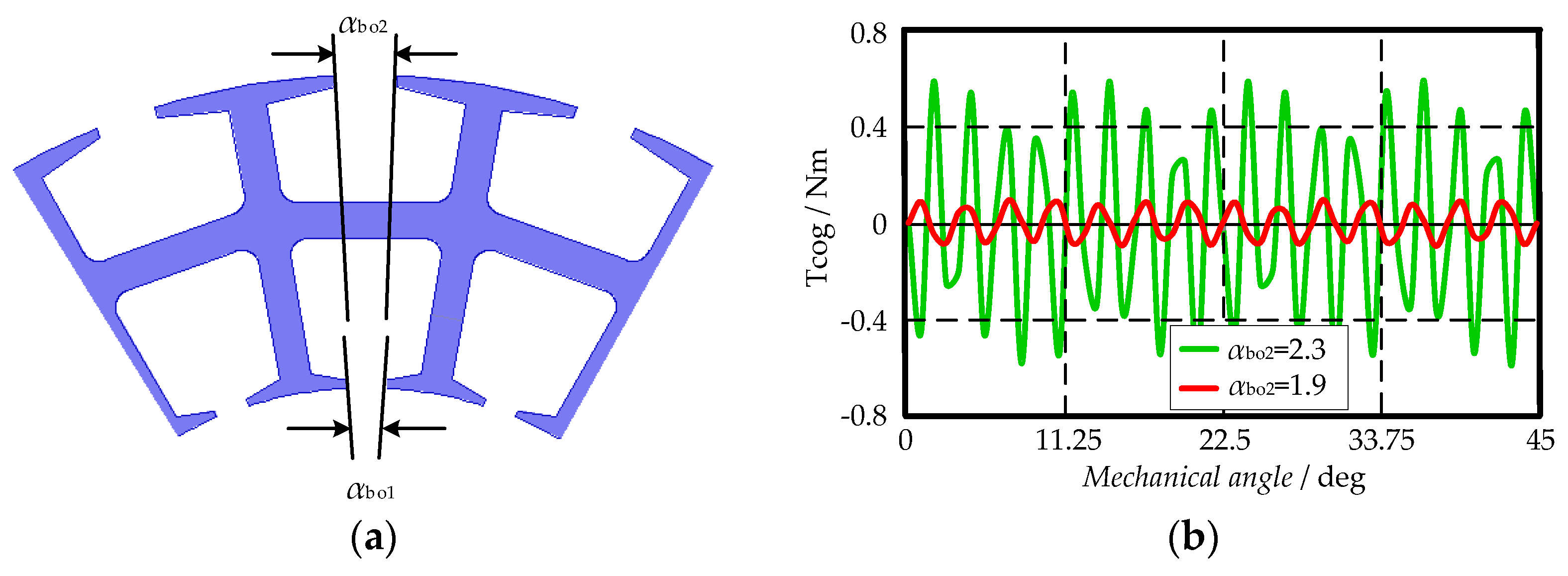
For the slotted structure, the cogging torque decreases as the slot opening angular width decreases. For the same slot opening angular, the arc length of the outer slot opening is larger than that of the inner one. In order to reduce the cogging torque, the outer slot opening angular α
bo2 can be designed to be smaller than α
bo1, as shown in
Figure 17a.
Figure 17b compares the cogging torque at different α
bo2. It can be seen that there is a big decline in the maximum cogging torque by changing α
bo2 from 2.3° to 1.9°. This implies that changing the opening angular is a valid approach to reduce the cogging torque of the DRRF generator. But it should be known that this method cannot completely eliminate the cogging torque.
5. Conclusions
In this paper, a comprehensive analytical model for a DRRF wind generator is developed based on EMC. Accurate calculations were performed, and results with rather high accuracy are obtained. The analytical model can precisely estimate the flux density distribution in the inner and outer air gaps as well as rotor and stator cores, back EMF waveform, both average and ripples of electro-magnetic torque, cogging torque, and other parameters. The results provided by the proposed model match well those from FEM analysis. That is, the analytical model developed in this paper can be employed in the preliminary design and analysis of the generator throughout the whole design process. Moreover, the working points of the ferrite magnets exceed the knee of the BH curve at different temperatures, which means the irreversible demagnetization does not occur at full load. Finally, the optimization is carried out by FEM to make the best use of the inner space of the generator, reduce the cogging torque, and decrease the THD of EMF. Accordingly, the optimal split ratio, pole arc ratio of the inner and outer rotor, as well as the outer slot opening has been obtained.


