Article

Research on Operation Principle and Control of Novel Hybrid Excitation Bearingless Permanent Magnet Generator

School of Electrical and Information Engineering, Jiangsu University, Zhenjiang 212013, China
*
Author to whom correspondence should be addressed.
Energies 2016, 9(9), 673; https://doi.org/10.3390/en9090673
Submission received: 24 May 2016 / Revised: 25 July 2016 / Accepted: 8 August 2016 / Published: 24 August 2016

Abstract

:
Under the condition of load changing, the magnetic field of traditional permanent magnet generators (PMG) is hard to be adjusted, and the mechanical bearings are significantly worn. To overcome the drawbacks above, a novel hybrid excitation bearingless permanent magnet generator (HEBPMG) is proposed in this paper, which has integrated the merits of hybrid excitation permanent magnet generators and magnetic bearings. Firstly, the structure and winding configuration of the HEBPMG are introduced, and then the principles of radial suspension and power generation are presented. The suspension principle as well as power generation principle is analyzed in this paper. Then, the flux linkage and induced voltage equations are derived, and the accurate mathematical model of radial suspension force is built based on the Maxwell tensor method. Subsequently, by means of the finite element analysis software-ANSYS Maxwell, the corresponding electromagnetic characteristics are analyzed to verify the correctness of the mentioned models. In addition, a compensation control strategy based on flux-linkage observation is proposed to solve the problems of unstable suspension force and generating voltage under variable load condition in this paper. Meanwhile, the corresponding control system is constructed and its feasibility is validated by simulation results. Finally, an experimental prototype of a 2.2 kW HEBPMG is tested. Experimental researches show that the HEBPMG can operate steadily under variable load condition and possess good suspension performance and power generation quality.

1. Introduction

Traditional permanent magnet synchronous generators (PMSGs) have the advantages of simple structure, high efficiency, high power factor, reliable operation and so on. They are widely applied in the wind turbine, gas turbine generator, aviation electric power source, hybrid vehicles, and flywheel energy storage system, with the operation reliability of the PMSG paramount [1]. However, in conventional PMSGs, the mechanical bearing is used to support the shaft, which causes heavy mechanical wear with the increase of rotation speed and limits the load capacity [2]. The bearing represents a bottleneck in achieving high-speed and ultra-high speed operation of the transmission system. Until the 1980s, the emergence of the bearingless motor extended the bearing service life of the generator and reduced the maintenance costs, while weakening the influence of bearing failure. Current researches mainly focus on the electromotion-state of the bearingless permanent magnet synchronous motors (BPMSMs) [3]. Because of their excellent starting and generating performance, the generating state is another working pattern for the BPMSM, namely bearingless permanent magnet generator (BPMSG), which is still in a preliminary exploratory stage and will be a hotspot in the future.
Due to the poor field adjustment ability of PMSG, the regulation of magnetic fields has been a hot research topic. It is an effective way to solve the problem by increasing the auxiliary electric excitation to adjust the magnetic field. In [4], a hybrid excitation type synchronous machine is presented by Nobuyuki Naoe et al., which has both permanent magnet and wound fields on the same shaft. Xiaogang Luo and Lipo A [5] proposed a synchronous permanent magnet hybrid AC machine. Juan A. Tapia et al. [6] designed a consequent pole permanent magnet machine with field weakening capability. However, there exists a coupling effect between permanent magnetic field and electric excitation magnetic field caused by the magnetic circuit structure of these motor. In addition, in [7,8], a hybrid excitation claw-pole synchronous generator with series magnetic circuit and a hybrid excitation claw-pole alternator are investigated, respectively. Their rotors are composed of permanent magnetic parts producing electricity and electrical excitation parts regulating voltage, and they are installed coaxially. By adjusting the exciting current, the air gap magnetic flux can be changed to realize the purpose of voltage stabilizing. However, these structures will cause defects in the resultant assembly process and high maintenance costs, aggravating the burden of the rotor, and reducing power density.
In this paper, a novel hybrid excitation bearingless permanent magnet generator (HEBPMG), in which the bearingless technology is utilized to realize the radial suspension and a set of excitation windings is added on the stator to compensate the synthesis of the magnetic field, is proposed. The structure of the HEBPMG and the operating principle are analyzed in Section 2. The voltage equations and the accurate mathematic model of suspension force are derived in Section 3. What is more, the correctness of the model is verified by finite element analysis (FEA). In terms of the instability suspension force and power voltage under variable loads, a compensation control strategy based on flux-linkage observation is proposed in Section 4. In Section 5, the corresponding digital control experiment platform is constructed. The simulation and experiment results verify the validity of the theoretical analysis and the effectiveness of the control system.

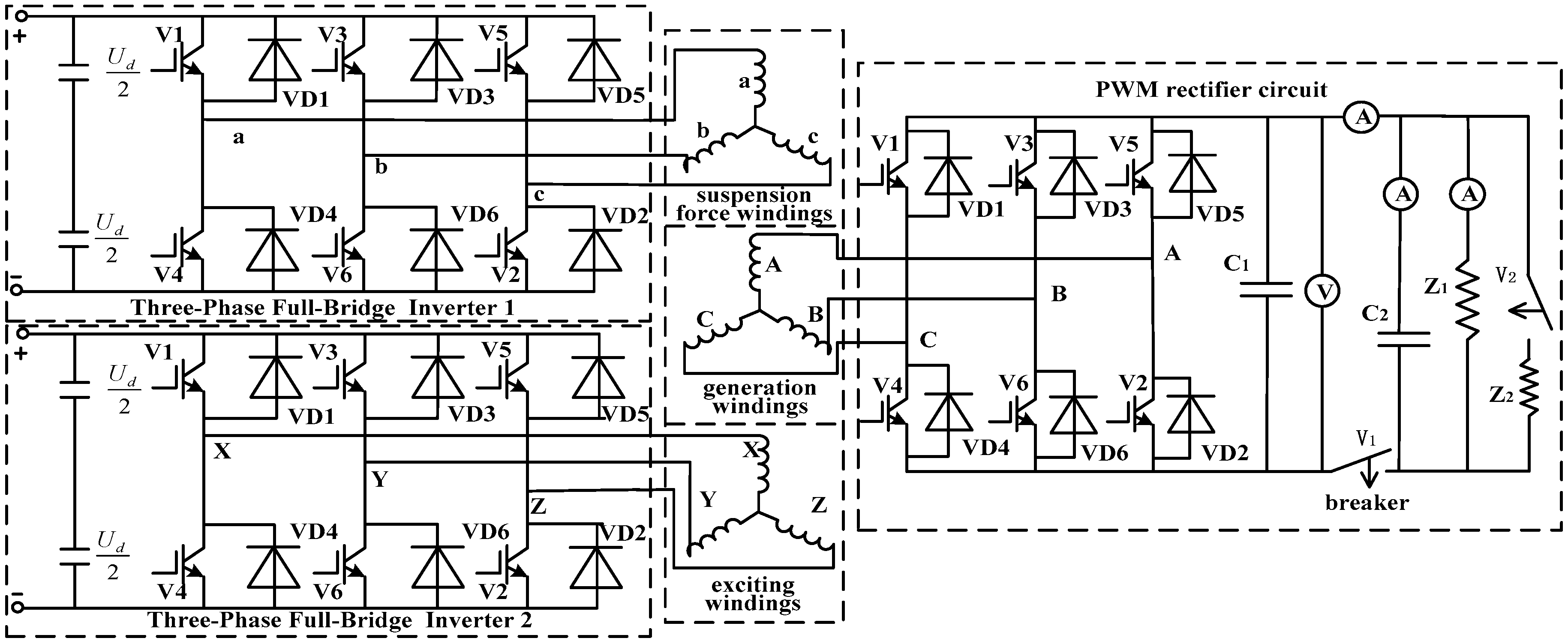
2. The Operation Principle and Structure of the HEBPMG

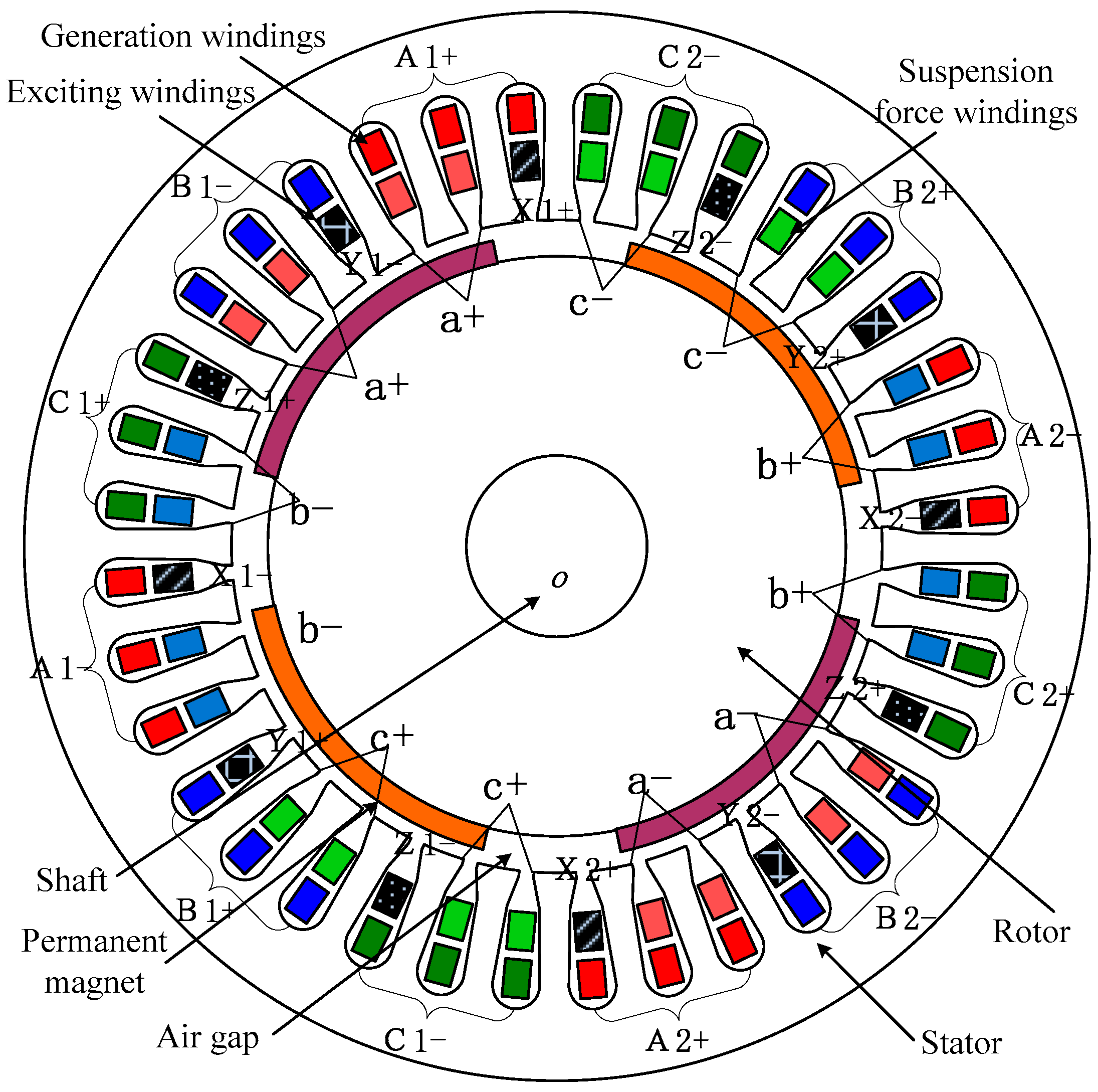
2.1. The Motor Structure and Windings Distributions of the HEBPMG

The radial profile sketch of the HEBPMG is shown in Figure 1. The HEBPMG adopts 36 stator slots, and there are three sets of windings dividing into two layers in the stator slot. Bottom layer windings are the generation windings, which are the distributed windings with three slots per pole and per phase form adopted. In a counter-clockwise direction, the winding phase sequence arrangement is A1+, B1−, C1+, A1−, B1+, C1−, A2+, B2−, C2+, A2−, B2+, C2−. For this arrangement, when the generation winding current is induced, the 2-pole-pair air gap magnetic field can be generated, which is equal to the pole number of the permanent magnet air gap magnetic field. In the upper layer windings, symbol X1+, Y1−, Z1+, X1−, Y1+, Z1−, X2+, Y2−, Z2+, X2−, Y2+, Z2− and a+, b−, c+, a−, b+, c− represent the exciting windings and the suspension force windings, respectively. Specifically, exciting windings X+ are arranged in the upper layer of the first slot among the three slots where the generation windings A+ are arranged in the bottom layer, and suspension force windings a+ are arranged in the upper layer of the second and the third slots. Generation windings B− are arranged in the bottom layer of the next three slots, in which the exciting windings Y− are arranged in the upper layer of the first slot, and the suspension force windings a+ are placed in the upper layer of other two slots. The exciting windings a+ slot here together with the above two a+ slots form an intact exciting windings a+. Taking three stator slots as an example, one exciting winding and two suspension force windings are arranged alternatively. By means of this winding structure, 1-pole-pair suspension force winding air gap field and 2-pole-pair generation winding air gap field can be generated to satisfy the principle of suspension for the HEBPMG [9]. The pole pairs of exciting winding air gap field is the same as that of the generator winding air gap field to realize the compensation and weakening effect for the resultant magnetic field.

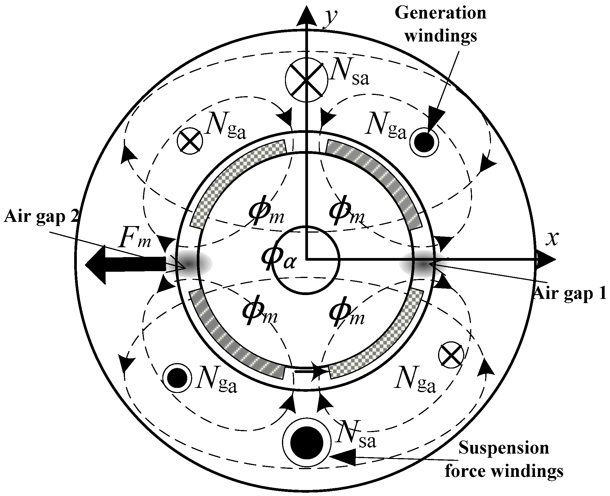
2.2. The Suspension Principle of the HEBPMG

In the HEBPMG, the given current signal of the suspension force windings is adjusted by real-time detecting the rotor radial displacement signal based on position sensor to realize self-aligning control. The suspension principle of HEBPMG is shown in Figure 2. Taking A-phase generation windings and a-phase suspension force windings as an example, the 2-pole-pair generator windings Nga and the 1-pole-pair suspension force windings Nsa are wound around the stator slots. When the suspension force windings are not energized, the air gap resultant magnetic field ϕm, consisting of the induced generation winding magnetic field and permanent magnet magnetic field, are spatially symmetric distributions. Then, according to Maxwell’s stress tensor, the radial suspension force Fm is zero. The 1-pole-pair air gap flux ϕα is generated when current is injected into the suspension force windings. As a result, the flux density is increased in the left and decreased in the right. Then the radial suspension force, namely Maxwell resultant force, Fm is obtained which points to the negative direction in the x-axis. A radial suspension force toward the positive direction of the x-axis can be acquired with a reverse current. Similarly, the radial suspension force in the y-axis can be obtained by providing corresponding current in the other windings. In summary, it is aimed to realize the rotor stable suspension based on radial displacement and the suspension force winding current closed-loop control.

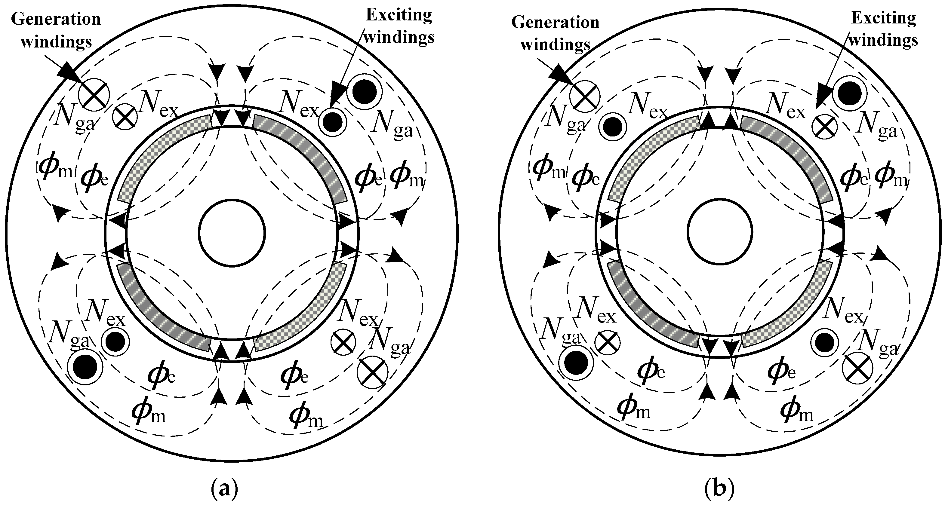
2.3. The Power Generation Principle of the HEBPMG

Compared with the traditional PMSG, HEBPMG has the same principle of power generation. Under driving of the prime motor, three phase induced currents can be generated by cutting magnetic induction lines of the permanent magnet rotation field. Figure 3 shows the external circuit of HEBPMG. The current flows into the load, generating voltage at both ends of the load. Where C represents capacitive load, Z represents resistance-inductance load, V represents breaker.
Exciting magnetic field ϕe will be changed by injecting the current in the exciting windings Nex to realize the magnetic-field compensation. As shown in Figure 4a, when the load is increased, air gap resultant magnetic field is weakening. To maintain stable operation, a strengthened excitation magnetic field must be provided. At this time, the direction of the exciting winding magnetic field is in accordance with that of the air gap resultant magnetic field. On the contrary, when the load is decreased, an excitation magnetic field in the opposite direction will weaken the resultant magnetic field. Thus, the quality of the power generation will be improved by adding the excitation magnetic field.

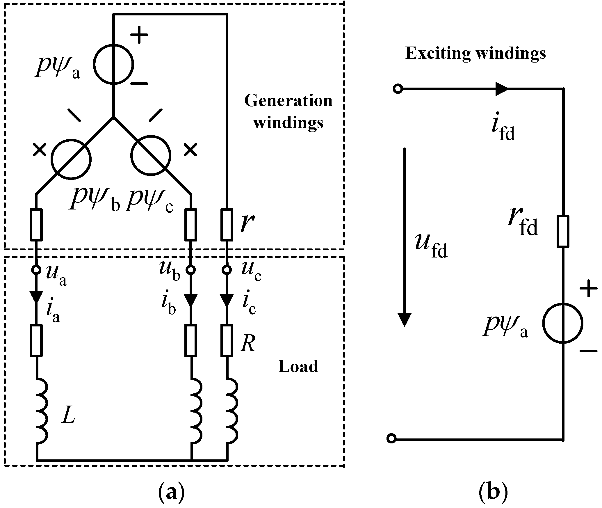
3. Mathematical Model of HEBPMG

3.1. Mathematical Model of Inducted Voltage

The equations of the flux linkage in the HEBPMG can be expressed as
{ ψ a = L aa i a M ab i b M ac i c M afd i fd + ψ pma ψ b = M ba i a L bb i b M bc i c M bfd i fd + ψ pmb ψ c = M ca i a M cb i b L cc i c M cfd i fd + ψ pmc ψ fd = M fda i a M fdb i b M fdc i c L ffd i fd + ψ pmfd
where Laa, Lbb, Lcc are self-induction of three phase generation windings. Mab = Mba, Mbc = Mcb, Mca = Mac are mutual inductance of three phase generation windings. Mfda = Mafd, Mfdb = Mbfd are mutual inductance between the generation windings and the excitation windings. Furthermore, ψpma, ψpmb, ψpmc are flux linkage generated by three generation windings and ψpmfd is the excitation winding flux linkage.
The equivalent circuit of the HEBPMG is shown in (Figure 5), and voltage equation can be expressed as
u ˙ s = d ψ ˙ s / d t + R s I ˙
where u ˙ s = [ua ub uc ufd]T is voltage matrix in which ua, ub, uc are the generation windings voltage at both ends and ufd is the excitation windings voltage. İ = [ia ib ic ifd]T is current matrix in which ia, ib, ic are the current of the generation windings and ifd is the excitation windings current. Rs = [−rrrrfd] is the resistance matrix in which r is the generation windings resistance and rfd is the excitation windings resistance. ψs = [ψa ψb ψc ψfd]T is flux linkage matrix in which ψa, ψb, ψc and ψfd are the generation windings and the excitation windings, respectively.

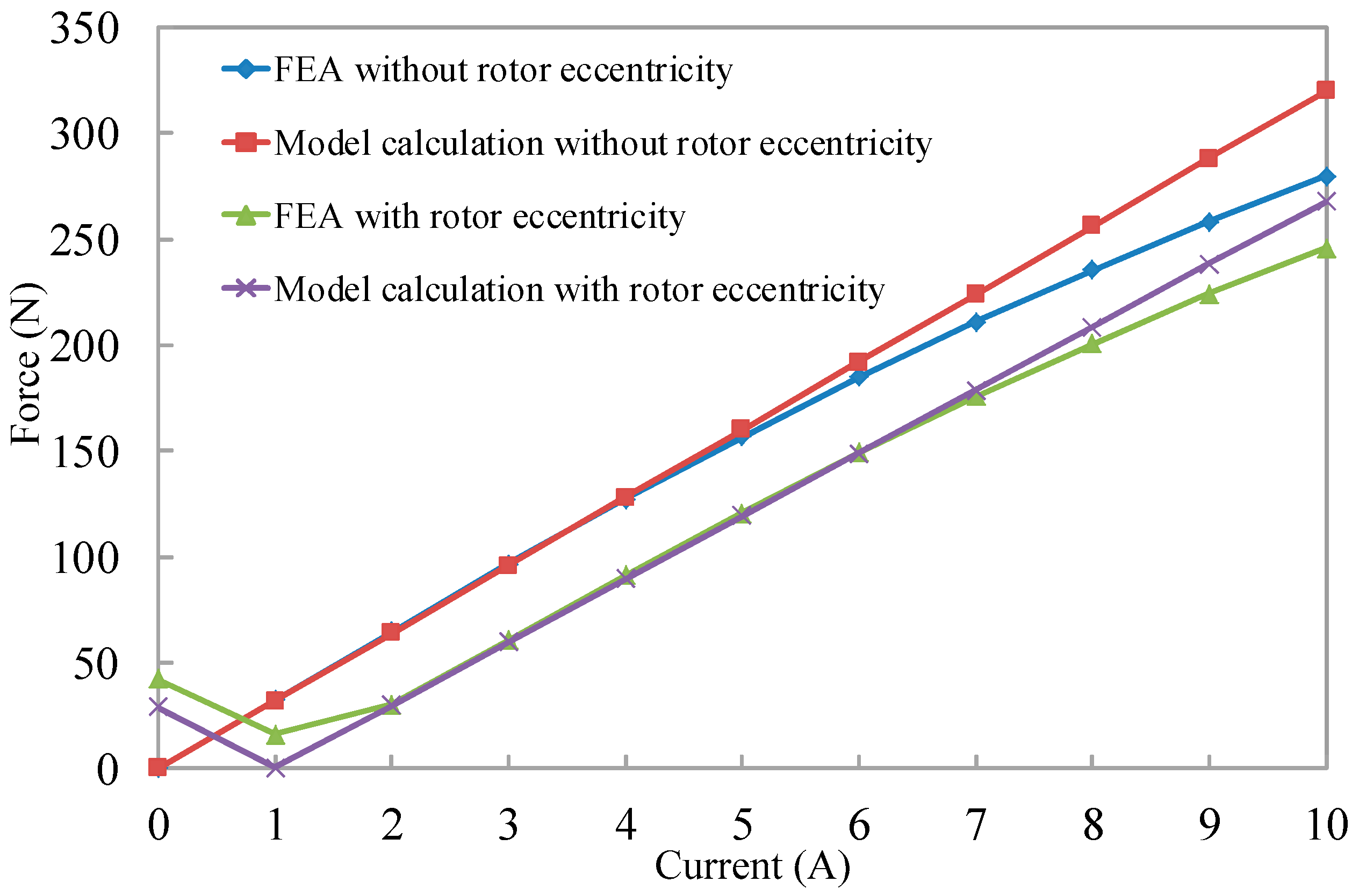
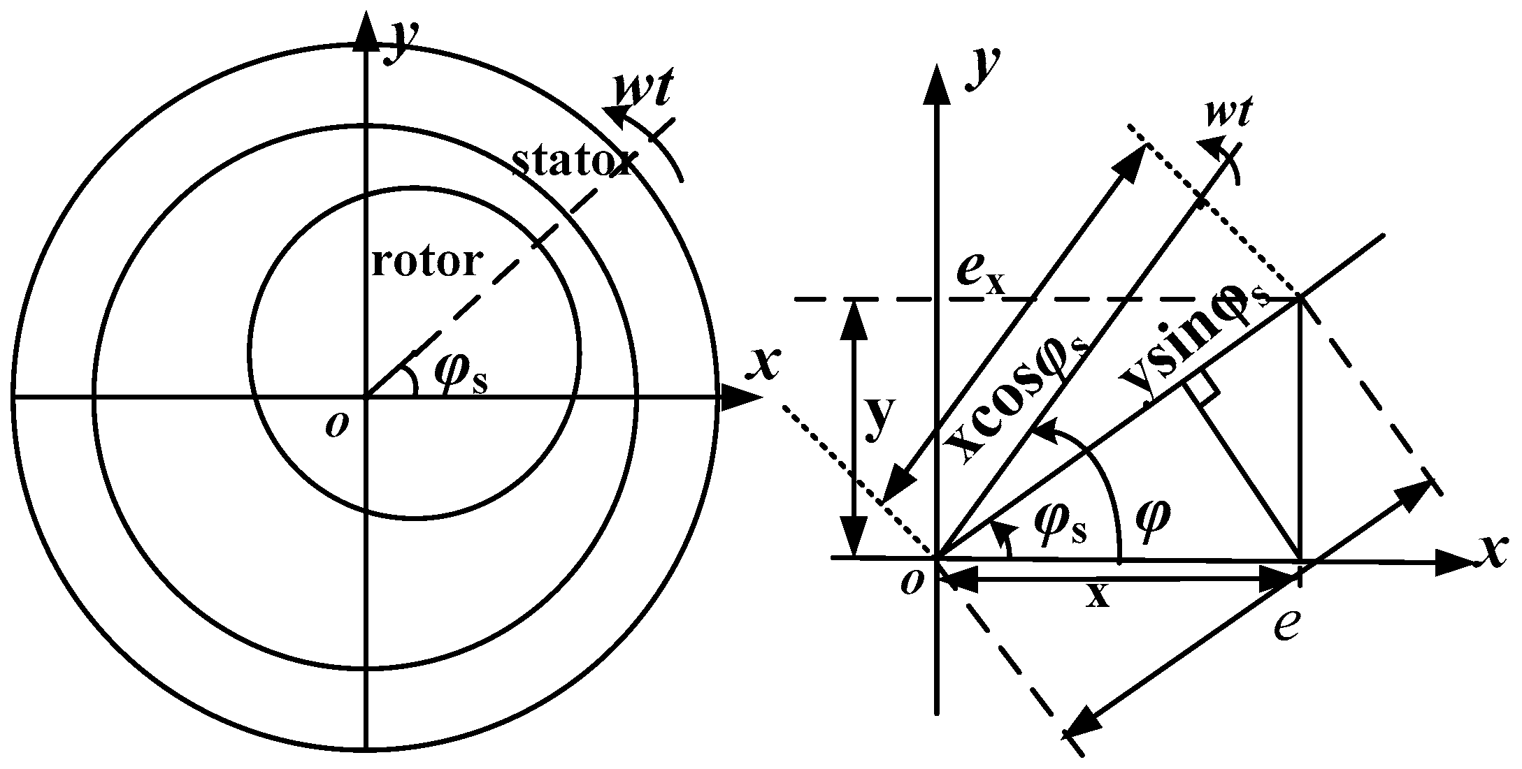
3.2. Mathematical Model of Radial Suspension Force

According to the electromagnetic field theory of the HEBSG, the resultant air gap magnetic field is generated by the generation windings, the permanent magnet, the suspension force windings and the exciting windings. The pole-pairs of the generation winding magnetic field, the permanent magnet and the exciting windings are identical, which can be represented as pG, and the magnetic field of the suspension force windings is pB-pole-pair. Above all, there are only two types of magnetic motive force (MMF) in the air gap for the HEBPMG. The fundamental component of MMF can be expressed as
f G ( φ , t ) = f 1 ( φ , t ) + f f ( φ , t ) + f 3 ( φ , t ) = F 1 m cos ( ω t p G φ μ 1 ) + F f m cos ( ω t p G φ μ f ) + F 3 m cos ( ω t p G φ θ 1 )
f 2 ( φ , t ) = F 2 m cos ( ω t p B φ λ 1 )
where, F1m, Ffm, F2m, F3m are the fundamental component amplitude of the air-gap MMF produced by the generation windings, the permanent magnet, the suspension force windings and the exciting windings, respectively. Meanwhile μ1, μf, λ1, θ1 are the initial phase angles of corresponding MMF fundamental wave, respectively. ϕ is the space angle. ω is the electric angular frequency of the generation windings current and the suspension force windings current.
According to the theory of Electrical Machinery, the value of F1m, Ffm, F2m, F3m is
{ F 1 m = 3 2 4 π 2 2 N 1 I 1 k d 1 p G   F 2 m = 3 2 4 π 2 2 N 2 I 2 k d 2 p B F f m = 3 2 4 π 2 2 N 1 I G k d 1 p G   F 3 m = 3 2 4 π 2 2 N 3 I 3 k d 3 p G
where, kd1, kd2 and kd3 correspond to the fundamental wave windings factors of the generation windings, the suspension force windings and the excitation windings, respectively, N1, N2 and N3 are the turn numbers in series of each phase of the generation windings, the suspension force windings and the excitation windings respectively. I1 is the induced current in the generation windings, I2 and I3 are the current injected respectively into the suspension windings and the excitation windings. IG represents the synthesis of current including the generation windings induced current, the excitation windings induced current and the equivalent current of permanent magnet.
Because the relative permeability of the stator core and the rotor core is much larger than that of air, the magnetic resistance of stator core and rotor core can be neglected. The air gap flux density can be obtained as
B ( φ , t ) = B ( φ , t ) + B ( φ , t ) = μ F δ cos ( ω t p φ μ ) + μ F δ cos ( ω t p φ λ )
δ = δ0 as the rotor is non-eccentricity. Considering the rotor eccentricity, the distribution of the air gap length is unbalance as shown in Figure 6. The air gap length in any direction is δ(ϕ) = δ0 − e·cos(ϕ − ϕs).
According to the Maxwell tensor method, the radial suspension force per unit area along an electric angle ϕ on the rotor surface can be expressed as
d F ( φ ) = B 2 ( φ , t ) 2 μ 0 d s = B 2 ( φ , t ) 2 μ 0 ( l r d φ )
where, l is the effective iron core length of HEBPMG, r is the rotor radius. For the HEBPMG (pG = 2, pB = 1), it is computed by the integral for Formula (7) with ϕ from 0 to 2π, and can be simplified as
{ F x = k m I G I 2 cos ( μ λ 1 ) + k n I G 2 [ x + x 2 + y 2 2 cos ( 2 ω t 2 λ 1 arctan y x ) ] F y = k m I G I 2 sin ( μ λ 1 ) + k n I G 2 [ y + x 2 + y 2 2 cos ( 2 ω t 2 λ 1 + arctan y x ) ]
Among them, k m = 9 2 μ 0 l r N 1 N 2 k d 1 k d 2 π δ 0 2 , k n = 9 4 μ 0 l r N 1 2 k d 1 2 π δ 0 2

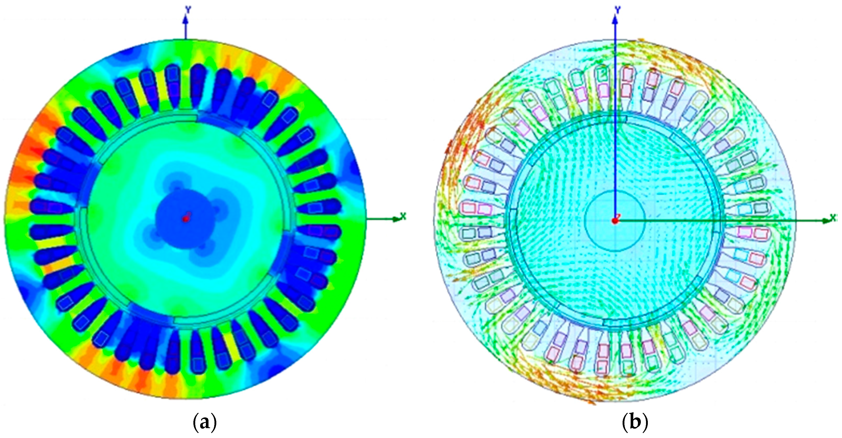
3.3. FEA Analysis of HEBSG

According to the structural model and working principle of the HEBPMG, the finite elements model is built utilizing ANSYS software for dynamic electromagnetic performance simulation. The structural parameters of the prototype are optimized through the analysis of parameterized, as shown in Table 1. The flux density cloud map and the distribution of magnetic field lines of HEBPMG are shown in Figure 7.
The PWM rectifier circuit shown as Figure 3 is connected to the generation windings of the HEBPMG. The PWM rectifier system can not only realize the adjustment of DC side voltage, but also enhance the power factor of the generator on the AC side, and reduce the harmonic of the generator current. Moreover, the flux linkage of the generation windings varies with the change of rotor position angle, which can generate back electromotive force (back-EMF). Then the induction current is generated and the voltage is formed on the load when the winding forms a return circuit, as shown in Figure 8.
The mathematical model derived in the second section can be validated by using the parameters in Table 1. The correctness of the model can be verified without rotor eccentricity in Figure 9. The radial suspension force on the permanent magnet rotor increases linearly with the increase of the suspension force windings current. However, on the other side, the increased speed of the suspension force value becomes slow and nonlinear due to saturation magnetic fields.
According to the results of the simulation, the angle between the vectors of the suspension force and the x-axis is 128° without rotor eccentricity. The rotor position angle is set to −52° which is the opposite direction of the suspension force. Therefore, the unilateral magnetic force and the controllable suspension force are in the opposite direction. When the suspension force current amplitude is small, the unilateral magnetic force plays the leading role in the radial suspension force. However, the controllable suspension force gradually increases with the increase of current, and there will be a point when the controllable suspension force is equal to the unilateral magnetic force. Then, after the balance point, the controllable suspension force continues to increase until it occupies the main part, the composition radial suspension force tends to be linear growth. Also, when current reaches a certain degree, there will be the trend of magnetic saturation. In general, conclusions can be drawn from the dynamic analysis of the simulation waveform and the established mathematical model is accurate.

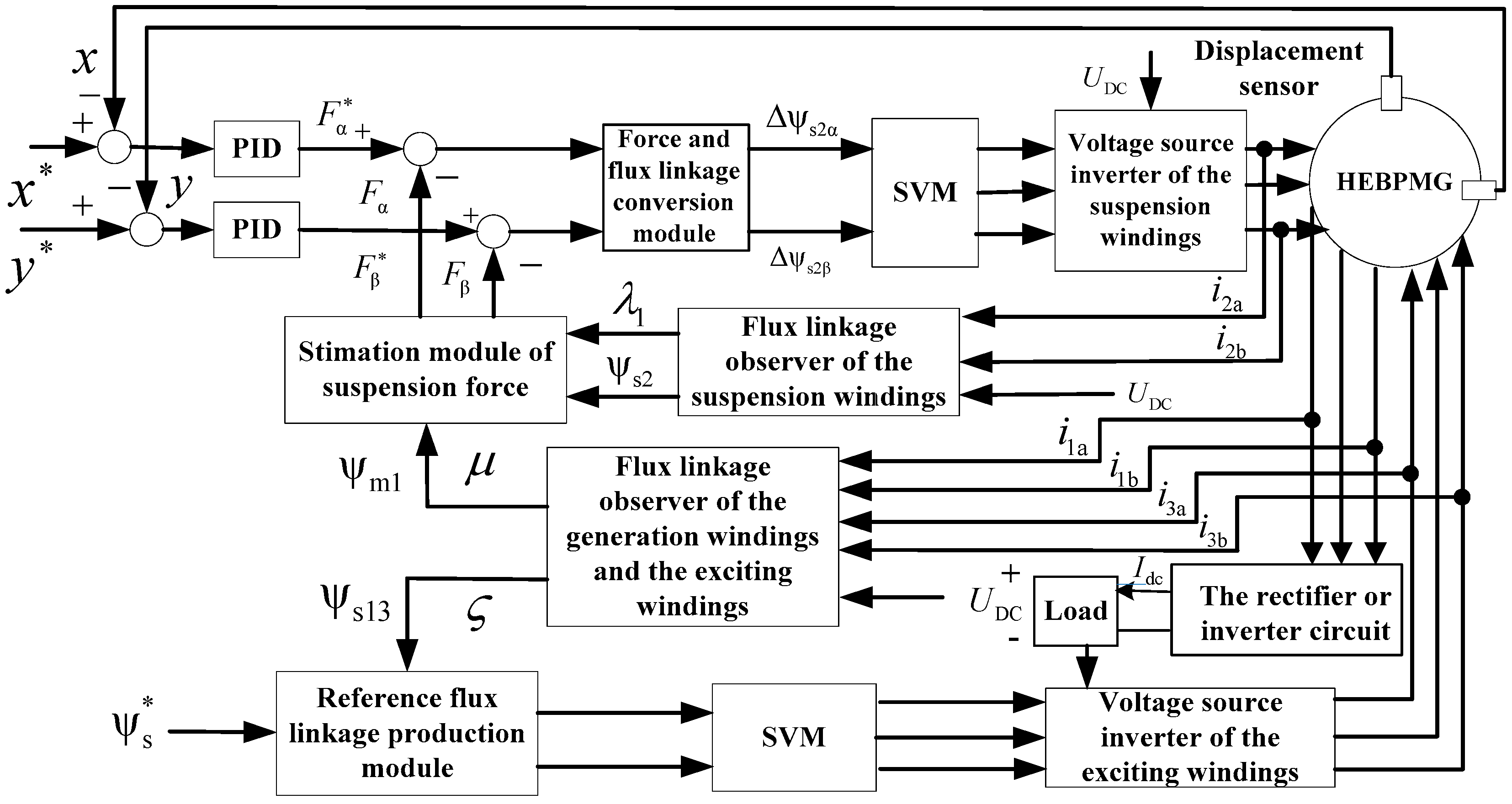
4. Control System of the HEBPMG Based on Flux Observation

In fact, the generator normally operates under the variable load condition, which causes instability of the suspension force and generating voltage. The air gap magnetic field used to generate power is determined by the permanent magnet, the generation windings and the excitation windings. Therefore, the generating performance can be improved by adjusting the amplitude of the excitation current for compensating the variable air-gap magnetic field. What is more, the stability of suspension force can be obtained by observing and adjusting the magnetic field generated by the suspension force windings. In consequence, flux-linkage observation is the key to controlling the suspension force and the generated voltage [10,11].
The flux-linkage of the generation windings, the excitation windings and the synthesis air gap flux-linkage can be observed with the following equations.
{ ψ s 1 α = ( u 1 α R 1 i 1 α ) d t ψ s 1 β = ( u 1 β R 1 i 1 β ) d t ψ s 1 = ψ s 1 β 2 + ψ s 1 α 2 μ 1 = arctan ( ψ s 1 β / ψ s 1 α )   { ψ s 3 α = ( u 3 α R 3 i 3 α ) d t ψ s 3 β = ( u 3 β R 3 i 3 β ) d t ψ s 3 = ψ s 3 β 2 + ψ s 3 α 2 θ 1 = arctan ( ψ s 3 β / ψ s 3 α )
ς = arctan ( ψ s 1 β + ψ s 3 β / ψ s 1 α + ψ s 3 α )
{ ψ m 1 α = ψ s 1 α + ψ s 3 α L 1 l i 1 α L 3 l i 3 α ψ m 1 β = ψ s 1 β + ψ s 3 β L 1 l i 1 β L 3 l i 3 β ψ m 1 = ψ s 1 β 2 + ψ s 1 α 2 μ = arctan ( ψ m 1 α / ψ m 1 β )
where ψs1, μ1 are the flux-linkage amplitude and phase of generation windings. ψs3 and θ1 are the flux-linkage amplitude and phase of excitation windings. ζ is the resultant flux-linkage phase of the generation windings and the excitation windings. ψm1, μ are the amplitude and phase of the resultant flux-linkage, L1l and L3l are the leakage inductance of the generation windings and the excitation windings.
The flux-linkage observation to the suspension force windings is as follows: ψs2, λ1 are the flux-linkage amplitude and phase of the suspension force windings.
{ ψ s 2 α = ( u 2 α R s i 2 α ) d t ψ s2 β = ( u 2 β R s i 2 β ) d t | ψ s2 | = ψ s2 α 2 + ψ s2 β 2 λ = arctan ( ψ s2 β / ψ s2 α )
When HEBPMG is operating stably, the rotor eccentricity is small enough to be neglected. The simplified equations of suspension force are as follows
{ F α = k m I G I 2 cos ( μ λ 1 ) F β = k m I G I 2 sin ( μ λ 1 )
While substituting ψm1 = IGLM, ψs2 = I2LB into the equations, the expression of suspension force on the current can be converted into an expression on the flux-linkage. The self-inductance of the excitation windings and the suspension force windings can be expressed as
L M = μ 0 π l r N 1 2 4 δ L B = μ 0 π l r N 2 2 4 δ , and then
{ F α = k m ψ m1 ψ s2 4 δ μ 0 π l r N 1 2 4 δ μ 0 π l r N 2 2 cos ( μ λ 1 ) F β = k m ψ m 1 ψ s 2 4 δ μ 0 π l r N 1 2 4 δ μ 0 π l r N 2 2 sin ( μ λ 1 )
Substituting the value of km, the estimation value of suspension force based on flux-linkage observation can be derived
{ F α = k w ψ m1 ψ s2 cos ( μ λ 1 ) F β = k w ψ m1 ψ s2 sin ( μ λ 1 )
where k w = 72 k d 1 k d 2 π 3 μ 0 l r N 1 N 2 .
Based on the strategy of the flux-linkage observation, the performance of suspension force and the generating voltage can be compensated under the variable load condition. Its control system block diagram is shown in Figure 10. Firstly, the induced current i1a and i1b in the generation windings and the excitation current i3a and i3b in excitation windings are acquired by the flux-linkage observer to calculate the resultant flux-linkage ψs13 and its phase ξ. After comparing the resultant flux-linkage with the given reference flux-linkage and being modulated by the space vector pulse width modulation (SVM) module, the switching signals for the voltage source inverter of the excitation windings is obtained. Therefore, the magnetic field can be controlled in closed loop.
Part of the force is controlled by radial displacement and suspension force double closed loop control system. Firstly, the current i2a and i2b of suspension force windings are collected. The suspension force windings flux linkage ψs2 and its phase λ1 is observed by suspension force windings flux-linkage observer. At the same time, the amplitude ψm1 and its phase μ of resultant flux-linkage are observed online by the generation and excitation windings flux-linkage observer. The suspension force Fα and Fβ can be calculated with these two sets of signals by the suspension force estimating module. Then, the errors between rotor position command values x*, y* and the detection values x, y which are observed from the displacement sensor are derived. Thus, the suspension force command values Fα* and Fβ* can be produced by the PID controller. The flux-linkage increment ∆ψs2α, ∆ψs2β of the suspension force windings can be derived from the errors between the calculated values and command values of the suspension force. Finally, the switching signals to voltage source inverter of suspension force windings can be obtained from the SVM module. In conclusion, the suspension force can be controlled.

5. Simulation and Experiment

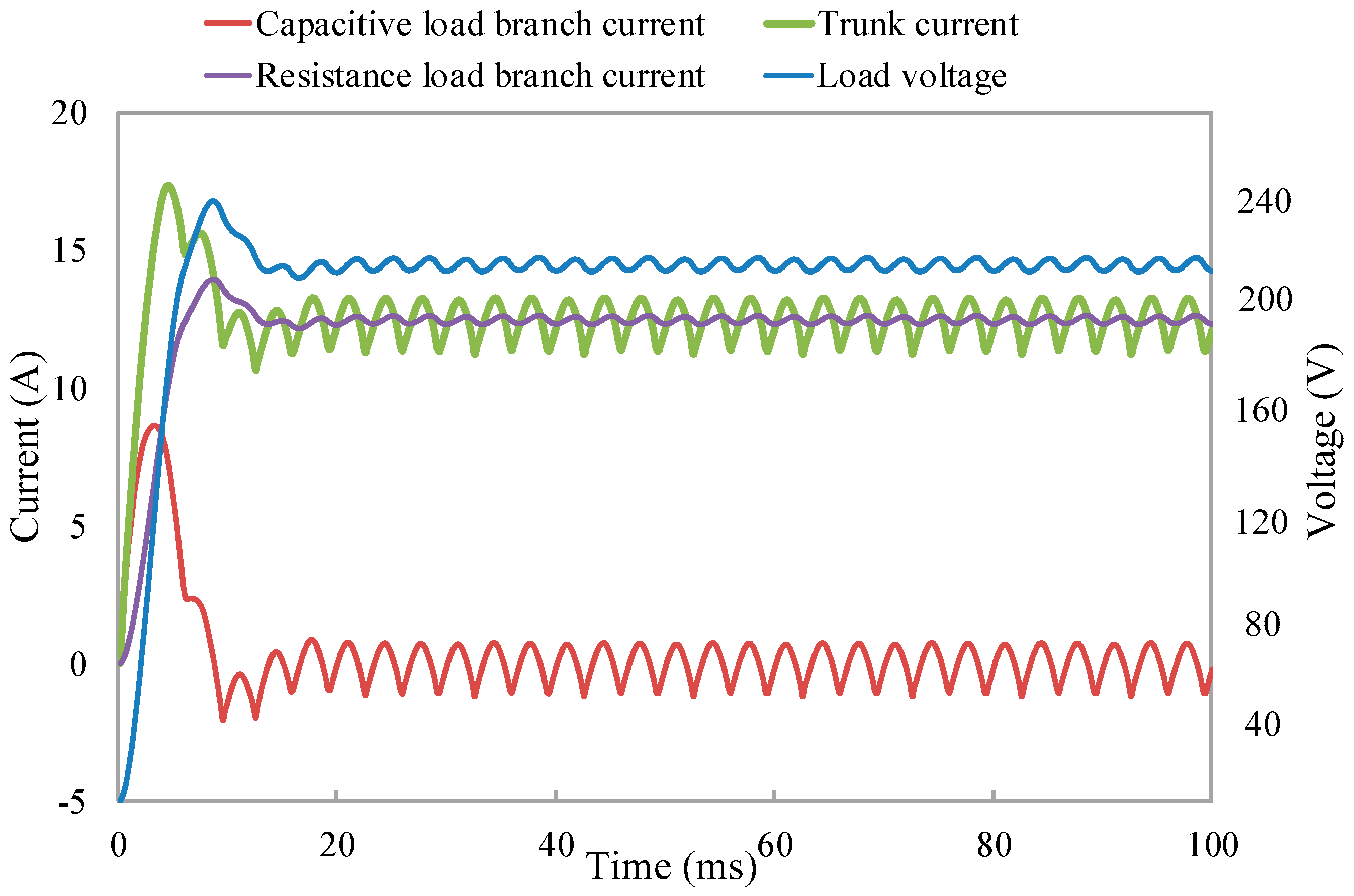
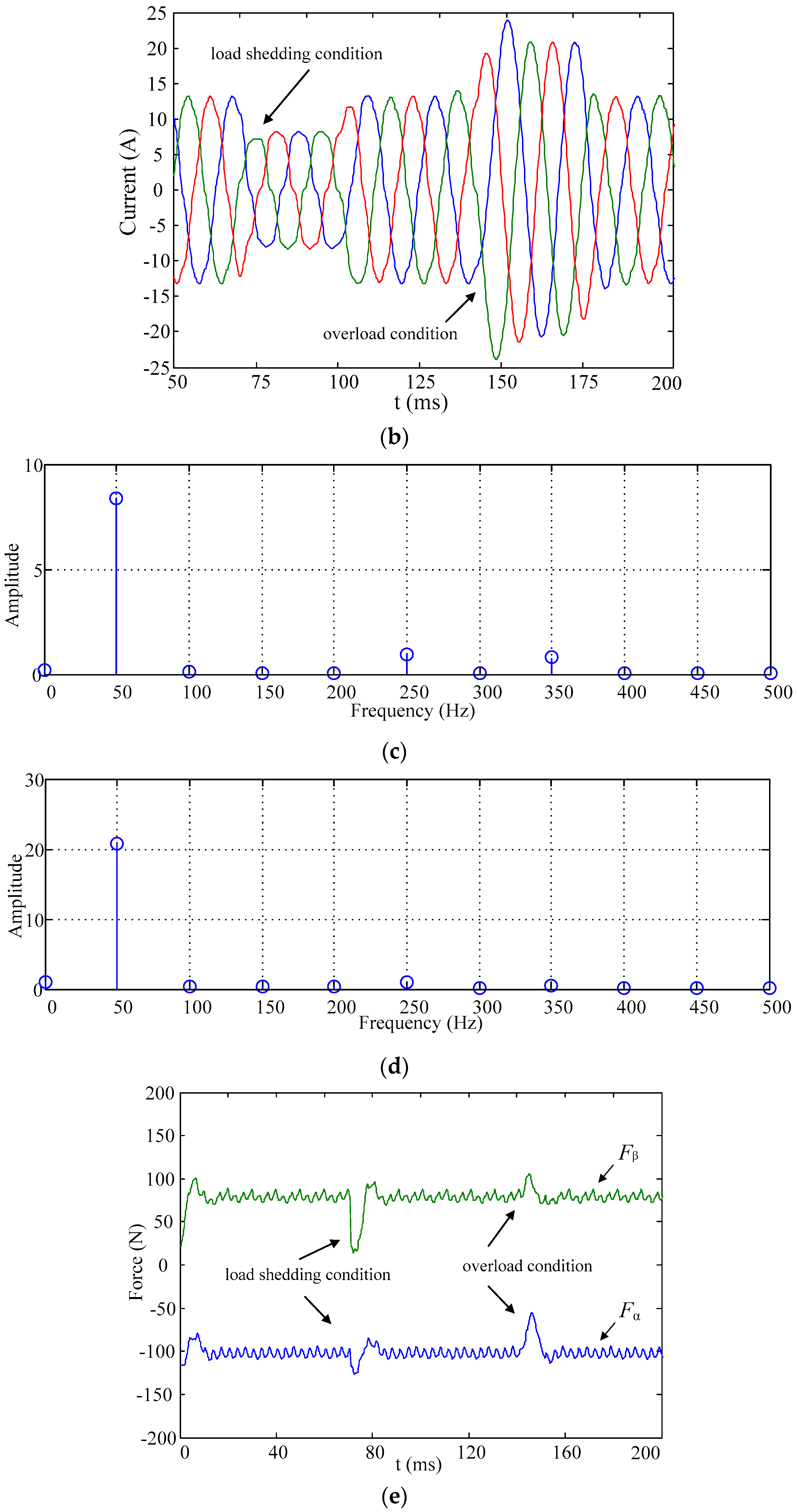
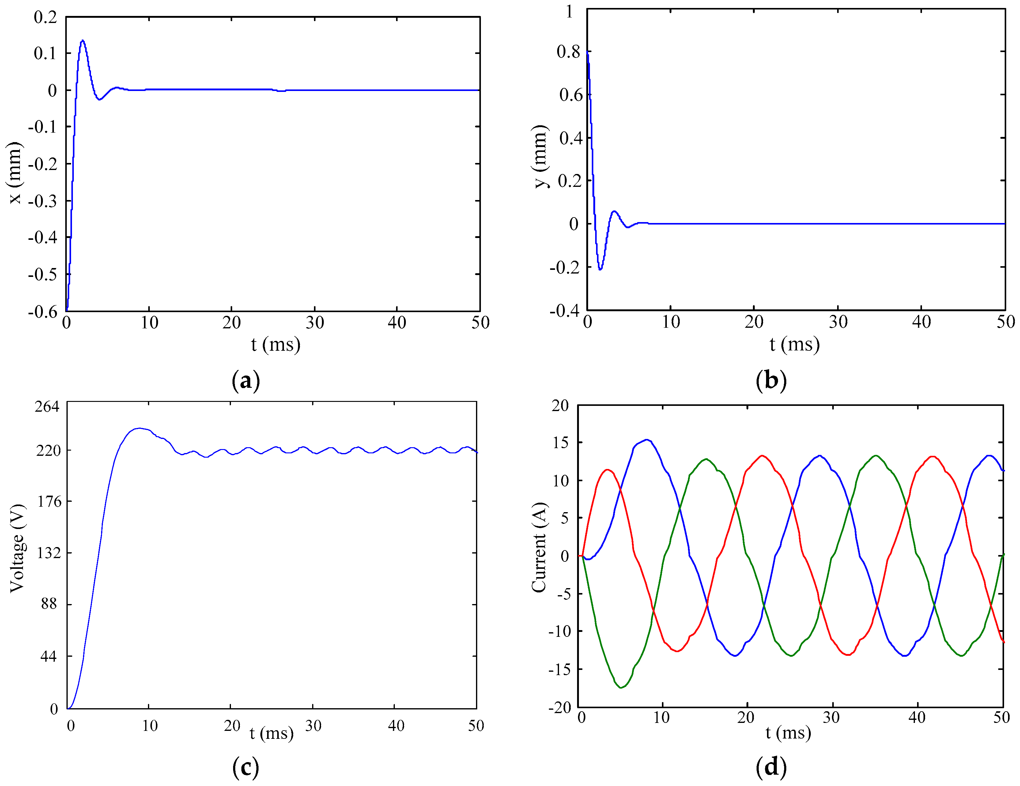
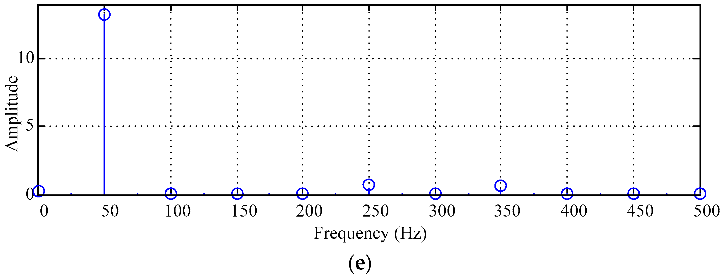
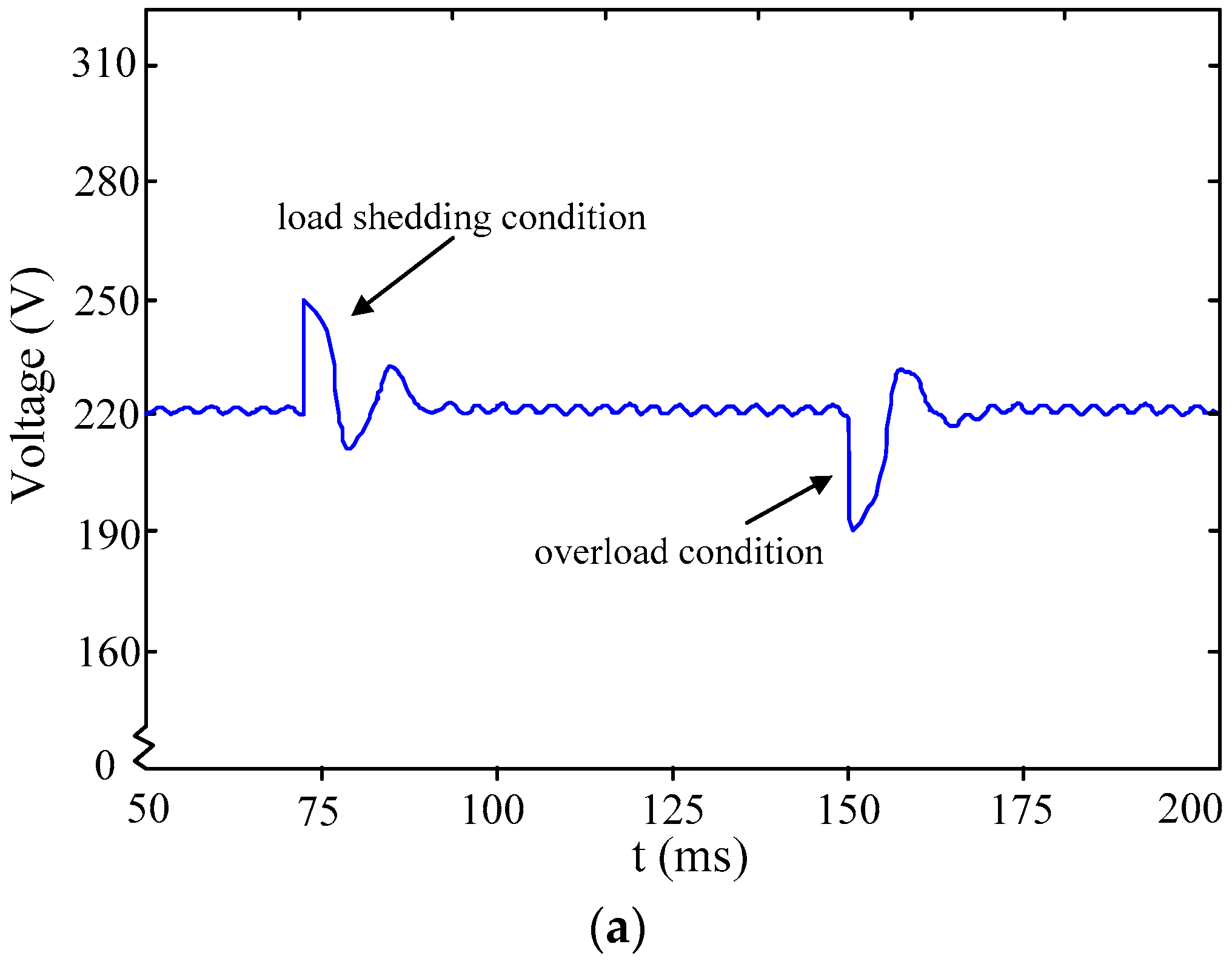
5.1. Simulation and Analysis

According to the flux-linkage observation and compensation system of flux linkage in Figure 10, the simulation module of HEBPMG controller system is built and experimented in the MATLAB/Simulink environment. Parameters of experiment are shown in Table 1, where the time of simulation is set to 0.2 s and the eccentricity of rotor is (−0.6 mm, 0.8 mm).
Simulation of stepping up from zero voltage experiment, which means progress of voltage rising from zero voltage to steady state, is shown in Figure 11. As depicted in Figure 11a,b, the original position of rotor is (−0.6 mm, 0.8 mm). When controller of radial suspension force is activated, rotor is set to balance location quickly after 8 ms. Maximal displacement in x-axis is 0.12 mm while in y-axis is 0.2 mm, which is accepted in eccentricity with accuracy control scheme and compensation circuits. When stepping up from zero voltage of the synchronous generator, the automatic voltage regulator should guarantee that the terminal voltage overshoot should not exceed 15% of the rated voltage, the time of adjustment should not more than 10 s, the frequency of voltage fluctuation should not be more than three times. The overshoot of voltage is 8.18% and the steady adjustment rate of voltage is 0.45% in Figure 11c, which satisfy the basic requirements of the control system [12]. After applying load, the output voltage returns to a steady state after 15 ms due to the modulation of excitation current. As can be seen in Figure 11d, the capacitance, inductance and other energy-storage elements of the load are in the charging state at the beginning of load work, then three-phase induction currents turn into steady state after 10 ms. The winding current is obtained by rectifying action of the external circuit shown in Figure 3. At 0 ms, closing the breaker V1 and opening V2, the generator operates under normal load conditions and the external circuit has a certain filtering effect at that time. It can be seen in Figure 11e that five harmonics and seven harmonics are generated by the methods of harmonic analysis under the condition of rated load, so it is good sinusoidal and THD1 = 4.59%.
For ensuring good static and dynamic performance of the HEBPMG system, the operation parameters of the motor must follow the command values quickly and accurately in the processes of load connection and disconnection. The external circuit is shown in Figure 3. At 0 ms, closing the breaker V1 and opening V2, the generator operates under normal load conditions. At 70 ms, opening V1 and remaining V2 as it was, the generator operates under load shedding conditions and the filtering function of the external circuit is weakened. It can be seen in Figure 12c that many five times harmonic and seven harmonics are generated by the methods of harmonic analysis under load shedding conditions, so there is poor sinusoidal and THD2 = 11%. At 140 ms, opening V2, the generator operates under overload conditions. The resistance-inductance load is added in the initial external circuit in order to enhance the filtering function. The winding current shows hardly any harmonics in Figure 12d under overload conditions, so sinusoidal performance is improved and THD3 = 1.38%. Figure 12 shows the results of anti-interference experiment of the HEBPMG control system based on flux-linkage observation. The output voltage effective value is shown in Figure 12a, and the generation winding induced current is shown in Figure 12b. When the system instantly cuts off load, the synthesized magnetic field of the generator is weakened but voltage increases quickly, three-phase induction currents decrease immediately and then tend to quickly become steady. The maximal overshoot of load disturbance is 30 V. It can be seen that the overshoot of the load disturbance is about 13.6% of the rating value and the time of adjustment is 0.02 s. These results meet the related theory [12]. When the load is applied instantly, the variation of the parameters is quite the contrary. Figure 12e indicates the whole variation progress of suspension force in x- and y-axis along with the variable load. The compensation strategy of flux-linkage observation allows the HEBPMG to quickly respond to commands, and the dynamic performance is improved.

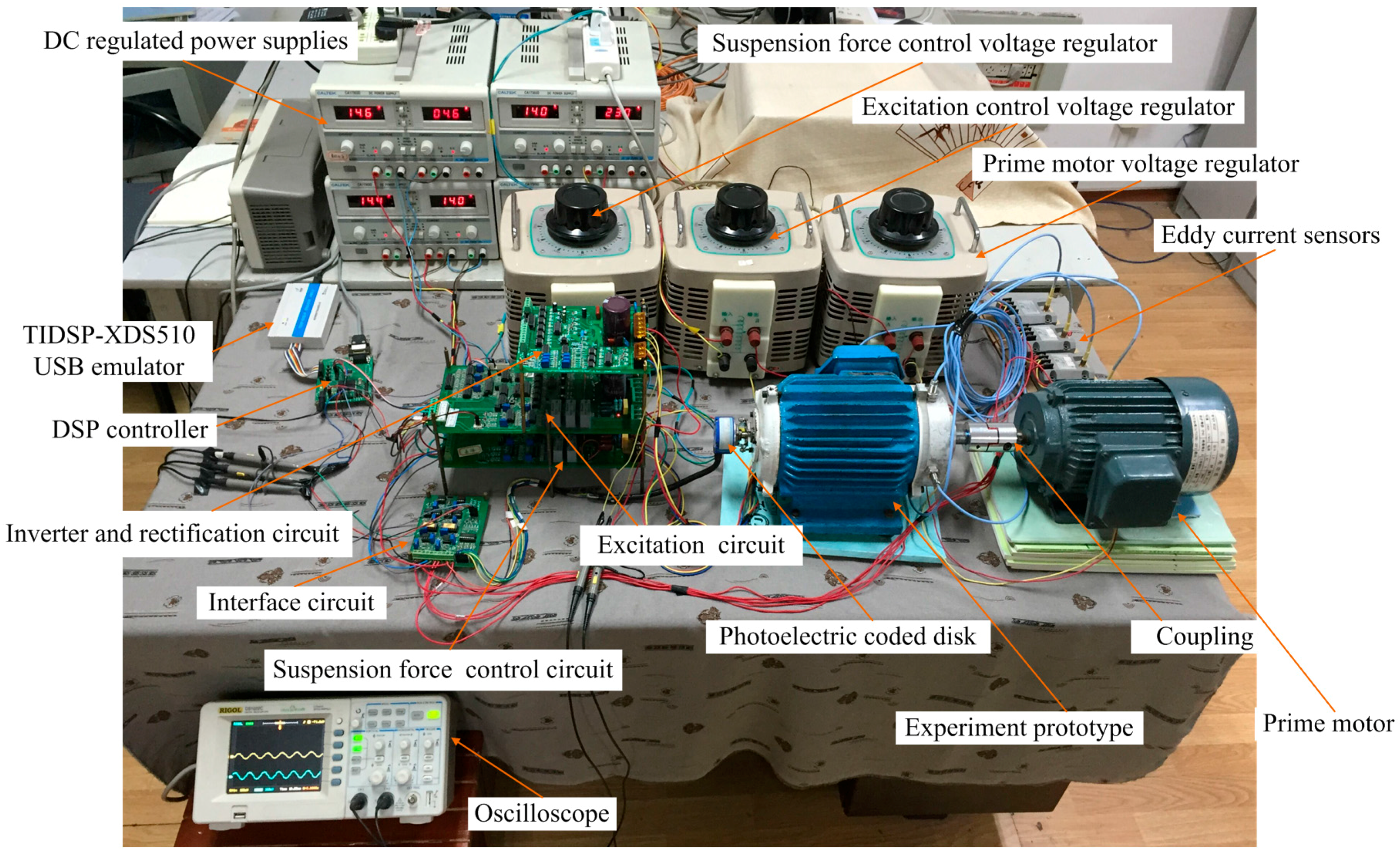
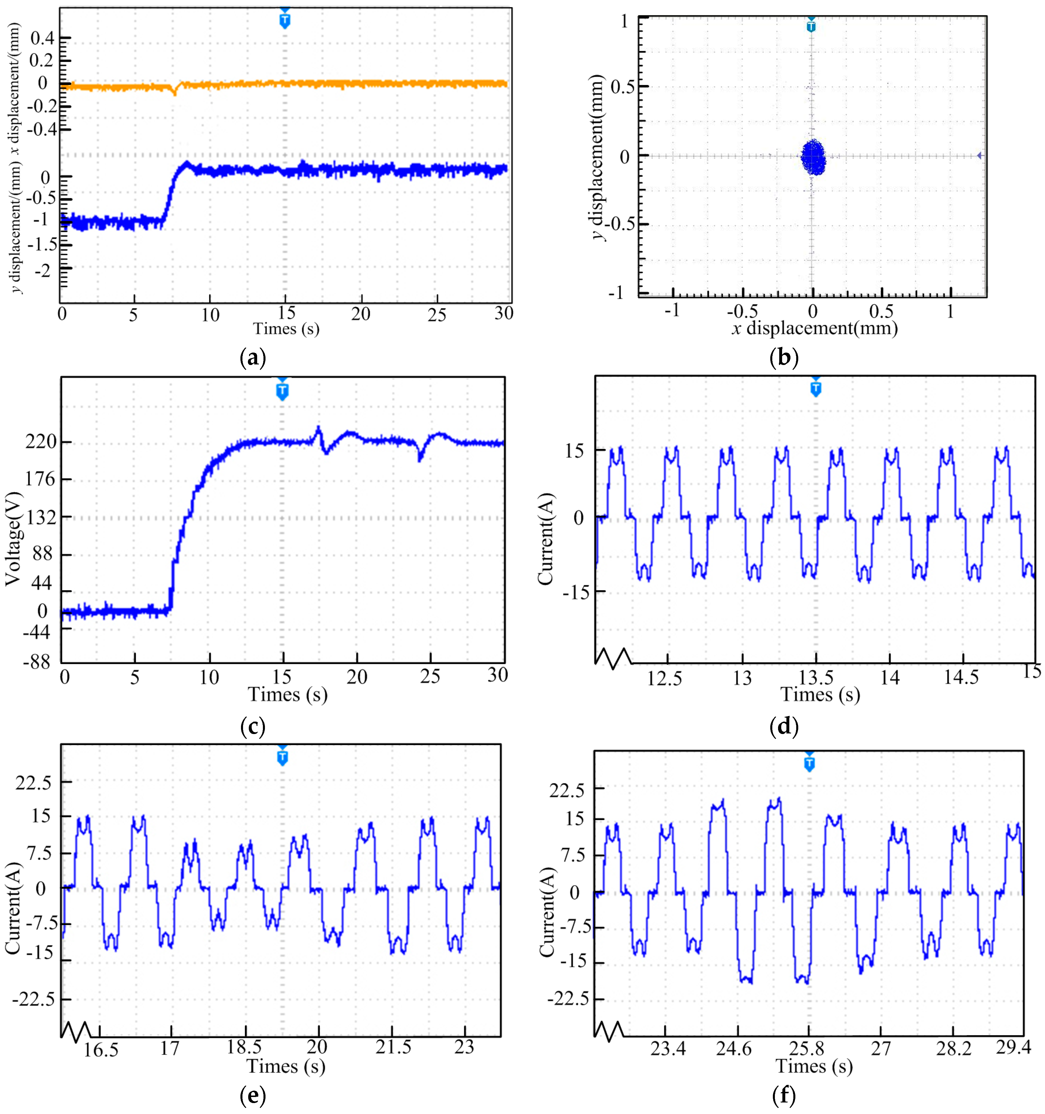
5.2. Experiment Result and Analysis

Based on flux-linkage observation, a 2.2 kW HEBPMG prototype is tested in Figure 13, and the experimental results will be compared with simulation results. Parameters of the HEBPMG are listed in Table 1. According to the control system block diagram in Figure 10, TMS320F2812 DSP is used as the digital controller of the experimental platform to realize the compensation control of magnetic field and suspension force. Intelligent power module (IPM) in the power board adopts Mitsubishi PS21265 to drive these three circuit boards, which has a bootstrap circuit and protecting function. An auxiliary bearing is installed, and the length between auxiliary bearing and shaft is δ1 = 300 μm. Voltage regulators are adopted to supply voltage for suspension force windings, excitation windings of HEBPMG and driving prime motor. VB 6.0 software is utilized for on-line adjustment of parameters in the experiment.
Due to the function of gravity, the initial position of rotor is (−0.04 mm, −0.9 mm), then the rotor returns to the balance position (0 mm, 0 mm) with the activation of the suspension control system, as shown in Figure 14a. In the y- direction, the rising time is 1.5 s while the declining time is approximately 1 s, maximal eccentricity is 0.3 mm and thus the maximum overshoot is less than 33.3%, which is much smaller than the air gap at the equilibrium point (Lg = 1 mm). In the x- direction, the vibration peak-to-peak value is approximately 0.12 mm. The deviations of radial displacements are acceptable. The displacement in y- direction is larger than that in x- direction due to the gravity. Thus, the eccentric displacement track diagrams are nearly-circular or elliptical, as depicted in Figure 14b. In order to verify the feasibility of the designed HEBPMG and the effectiveness of the proposed compensation control strategy based on flux-linkage observation, the generating voltage and the winding current waveform under different load conditions are shown in the following figure. Figure 14c is DC voltage in the process of operation. First of all, the generating voltage gradually increases from start to operating stably. Then, the fluctuation errors of DC voltage are about 4% under load shedding and overload conditions. The generating voltage restores stability after overshoot, respectively. Meanwhile, the AC current in the process of operation is shown in Figure 14d–f. It can be seen in in Figure 14d that the AC current will be stabilized about 15 A after reaching stable operation. As shown in Figure 14e, winding current amplitude is reduced in 17 s and then recovered to the rated value in a short time through the role of compensation control under load shedding conditions. Subsequently, it can be seen in Figure 14f that the winding current amplitude is raised in 24 s under overload conditions. Then, the winding current is recovered to the rated value in a short time based on flux-linkage observation too. The results above indicate that the proposed compensation and control strategy has high accuracy, good dynamic response and satisfactory anti-interference ability.

6. Conclusions

In this paper, the motor structure and operation principle of a novel HEBPMG system are analyzed in detail. Then, the mathematic model of induction voltage and suspension force is deduced and tested by FEM software to prove its feasibility. A new compensation and control strategy is presented according to flux-linkage observation. Finally, both the simulation and experimental results prove that the proposed compensation and control strategy has satisfactory performance in adjustment of suspension force, generating voltage and winding current. What is more, the effects on suspension force, voltage and current caused by load variation are weakened.

Acknowledgments

This work was sponsored by National Natural Science Foundation of China (51675244), Key Research and Development Program of Jiangsu Province (BE2016150), Jiangsu Province University Achievements in Scientific Research Industrial Production Advancement Project (JHB2012-39), Jiangsu Province “333 Project” Research Projects (2014), Jiangsu Province “Qinglan Project” (2014).

Author Contributions

Huangqiu Zhu proposed the control method and performed simulation analysis and assisted in control software compilation test, Yamin Hu carried out the modification of the winding configuration and drafted the manuscript.

Conflicts of Interest

The authors declare no conflict of interest.

References

  1. Ooshima, M.; Kitazawa, S.; Chiba, A.; Fukao, T. Design and analyses of a coreless-stator-type bearingless motor/generator for clean energy generation and storage systems. IEEE Trans. Magn. 2006, 42, 3461–3463. [Google Scholar] [CrossRef]
  2. Ooshima, M.; Kobayashi, S.; Tanaka, H. Magnetic suspension performance of a bearingless motor/generator for flywheel energy storage systems. In Proceedings of the 2010 IEEE Power Engineering Society General Meeting, Minneapolis, MN, USA, 25–29 July 2010; pp. 1–4.
  3. Xu, Y.; Patterson, D.; Hudgins, J. Permanent magnet generator design and control for large wind turbines. In Proceedings of the 2012 IEEE Power Electronics and Machines in Wind Applications, Denver, CO, USA, 16–18 July 2012; pp. 1–5.
  4. Naoe, N.; Fukami, T. Trial Production of a Hybrid Excitation Type Synchronous Machine. In Proceedings of the IEEE International Electric Machines and Drives Conference, Cambridge, MA, USA, 17–20 June 2001; pp. 545–547.
  5. Luo, X.G.; Lipo, T.A. A synchronous/permanent magnet hybrid AC machine. IEEE Trans. Energy Convers. 2000, 15, 203–210. [Google Scholar]
  6. Tapia, J.A.; Leonardi, F.; Lipo, T.A. Consequent-pole permanent-magnet machine with extended field-weakening capability. IEEE Trans. Ind. Appl. 2003, 39, 1704–1709. [Google Scholar] [CrossRef]
  7. Zhang, D.; Zhao, C.; Zhu, L. On hybrid excitation claw-pole synchronous generator with magnetic circuit series connection. In Proceedings of the ICEMS 2008 International Conference, Wuhan, China, 17–20 October 2008; pp. 3509–3513.
  8. Ni, Y.; Wang, Q.; Bao, X. Optimal design of a hybrid excitation claw-pole alternator based on a 3-D MEC method. Int. Conf. Electr. Mach. Syst. 2005, 1, 27–29. [Google Scholar]
  9. Sun, X.D.; Chen, L.; Yang, Z.B. Overview of bearingless permanent-magnet synchronous motors. IEEE Trans. Ind. Electron. 2013, 60, 5528–5538. [Google Scholar] [CrossRef]
  10. Wang, Y.; Deng, Z.Q. A stator flux estimation method for direct torque linear control of electrical excitation flux-switching generator. In Proceedings of the IEEE Conference and Expo of Transportation Electrification Asia-Pacific (ITEC Asia-Pacific), Beijing, China, 31 August–3 September 2014; pp. 110–116.
  11. Wang, Y.; Deng, Z.Q. Improved Stator Flux Estimation Method for Direct Torque Linear Control of Parallel Hybrid Excitation Switched-Flux Generator. IEEE Trans. Energy Convers. 2012, 27, 747–756. [Google Scholar] [CrossRef]
  12. Chen, H. The Power System Steady State Analysis, China; China Electric Power Press: Beijing, China, 2007; pp. 240–243. [Google Scholar]
Figure 1. The structure and windings distributions of the hybrid excitation bearingless permanent magnet generator (HEBPMG).
Energies 09 00673 g001
Figure 2. The suspension principle of HEBPMG.
Energies 09 00673 g002
Figure 3. The external circuit of HEBPMG.
Energies 09 00673 g003
Figure 4. The excitation principle of HEBPMG. (a) The synthesis of magnetic field is compensated by excitation magnetic field; (b) The synthesis of magnetic field impaired by excitation magnetic field.
Energies 09 00673 g004
Figure 5. The equivalent circuit of HEBPMG (a) The equivalent circuit of power generation; (b) The equivalent circuit of excitation.
Energies 09 00673 g005
Figure 6. The definition of rotor eccentricity.
Energies 09 00673 g006
Figure 7. The finite element model of HEBPMG (a) Flux density cloud map; (b) The distribution of magnetic field lines.
Energies 09 00673 g007
Figure 8. The load current and voltage of Pulse Width Modulation (PWM) rectifier circuit.
Energies 09 00673 g008
Figure 9. The relationship between radial levitation force and levitation force winding current amplitude.
Energies 09 00673 g009
Figure 10. The compensation control block diagram of the flux-linkage observation.
Energies 09 00673 g010
Figure 11. The performance of generator and harmonic analysis under normal operation. (a) Rotor floating waveform in x axis; (b) Rotor floating waveform in y axis; (c) The output voltage effective value; (d) The generation winding induced current; (e) Winding current harmonic under the rated load.
Energies 09 00673 g011aEnergies 09 00673 g011b
Figure 12. The performance of the generator and harmonic analysis during load disturbance. (a) The output voltage effective value; (b) The generation winding induced current; (c) Winding current harmonic under load shedding condition; (d) Winding current harmonic under overload condition; (e) The suspension force in the process of operation.
Energies 09 00673 g012aEnergies 09 00673 g012b
Figure 13. The experimental results based on compensation control strategy of flux-linkage observation.
Energies 09 00673 g013
Figure 14. The experimental results based on compensation control strategy of flux-linkage observation. (a) Radial displacement waveforms of x- and y-direction when the start of suspension; (b) The relationships between radical displacement of x- and y-direction for HEBPMG; (c) Generating voltage of HEBPMG in the process of operation; (d) The winding current waveform under rated load; (e) The winding current waveform under load shedding conditions; (f) The winding current waveform under overload conditions.
Energies 09 00673 g014
Table 1. Structural parameters of the prototype.
SymbolQuantityValue
QStator slot counts36
DS1Outer diameter of stator180 mm
DS2Inner diameter of stator110 mm
Dr1Outer diameter of rotor98 mm
Dr2Inner diameter of rotor30 mm
LgRadial length of air-gap1 mm
lAxial length of rotor50 mm
PRated power2.2 kW
Stator slot full rate0.75
ISuspension force winding current5A
ФWindings wire diameter0.71 mm
Material of stator and rotorD32_50
Material of permanent magnet rotorNFeB35
Magnetization of permanent magnet rotorparallel magnetization
haAuxiliary bearing thickness0.7 mm
PMPole-pair of generation windings2
PBPole-pair of suspension windings1
PEPole-pair of excitation windings2
N1Turns in series of each phase of generation windings40
N2Turns in series of each phase of suspension windings60
N3Turns in series of each phase of excitation windings40
JThe rotational inertia0.00059 kg·m2

