1. Introduction
In terms of renewable energy, there is a long list of energy types that comes from various natural resources such as solar, wind, geothermal, sea tide, and biomass. Among them, photovoltaic (PV) from solar is much preferable due to its implementation simplicity with less maintenance. In recent years, PV systems have witnessed neverending demand due to their enormous potential to be the nearest solution we have right now to substitute our diminishing fossil fuel energy sources. When a PV panel is exposed to solar irradiation, it can generate direct current electricity without any environmental impact or contamination. The only drawbacks are that the cost to manufacture PV panels is too high and their small range of efficiency is only about 15%–20% [
1,
2,
3].
PV panels have nonlinear output characteristics and the main factors affecting PV output power are the solar irradiation, temperature and load impedance [
3]. When the solar irradiation rises, the PV current increases, however, the temperature of a PV module has a more significant effect on PV voltage operation [
4]. Due to the nonlinear output characteristics of PV panels, an algorithm is needed to track the maximum power point (MPP) of the PV curve to deliver the maximum power. This is known as maximum power point tracking (MPPT). The MPPT operation basically involves finding the maximum operating voltage and current at which PV operates to achieve the MPP. Many MPPT methods have been developed and implemented [
4,
5]. Among them are perturb and observe (P&O), incremental conductance (IC), artificial neural network (ANN), fuzzy logic controller (FLC), constant voltage, three-point weight comparison, short current pulse, and open circuit voltage. The most commonly used traditional methods are P&O and incremental conductance, however, potential artificial intelligent techniques like FLC and ANN are recently gaining popularity in MPPT design due to their ability to achieve higher stability and less noise factor [
6]. Specifically, FLC does not require an accurate mathematical model and is known to be very efficient in handling problems that have non-linear variables [
6].
Meanwhile, the amount of DC-based equipment operated at various levels is growing higher, and thus, having a DC-DC converter with ability to produce various DC outputs is preferable. The SEPIC converter is preferable due to its ability to buck and boost input voltage and has advantage of having non-inverted output. By having non-inverted output polarity, implementation of circuit to load becomes easier due to the fact the reference point (ground) is the same. There are quiet a number of significant works on SEPIC with PV [
7], which also covers MPPT algorithms, including FLC [
8]. As MPPT tracks maximum power via increasing or decreasing voltage and current, SEPIC is effective as it increases and decreases voltage at the current’s expense [
9].
However, in related to FLC MPPT for SEPIC, there are no such works considering comprehensive evaluations of MPPT for both buck and boost operations. By using only a single FLC for MPPT, although it performs better as compared to P&O [
10], using just a common pattern of membership functions may degrade its performance to track MPP, especially when facing dynamic irradiance changes. In addition, at the controller output for producing a PWM signal to power switching devices in SEPIC, this type of MPPT is only suitable to be set as a duty cycle change which will be added to a pre-defined duty cycle. Use of a direct duty cycle approach is totally unsuitable. Consequently, when the irradiance changes rapidly, there is a possibility that the single-FLC MPPT will fail to track its MPP and take a certain amount of time to reach steady state conditions [
11,
12].
Therefore, this paper proposes a dual-FLC MPPT that offers a significant improvement of both buck and boost operations in SEPIC. Design of membership functions for each FLC will be carried out by focusing to each specific problem in buck and boost operations, respectively. Hypothetically, as further proven later in this paper, during buck operation, a high overshoot voltage exists, and during boost operation, an undershoot voltage occurs, both during the initial period of changes. Thus, the proposed MPPT should ensure not only operation of SEPIC at MPP, but also should address the mentioned problems, both in simulation and experimental works. Two separate loads with a switching circuit, called as load changing circuit, are set up to ensure a significant impact of dynamic changes can be provided during evaluation of the proposed MPPT. As for the rest of this paper,
Section 2 covers the proposed PV-based system, followed by a description of the proposed MPPT in
Section 3, and both simulation and experimental validations in
Section 4 and
Section 5, respectively. Finally
Section 6 concludes the findings.
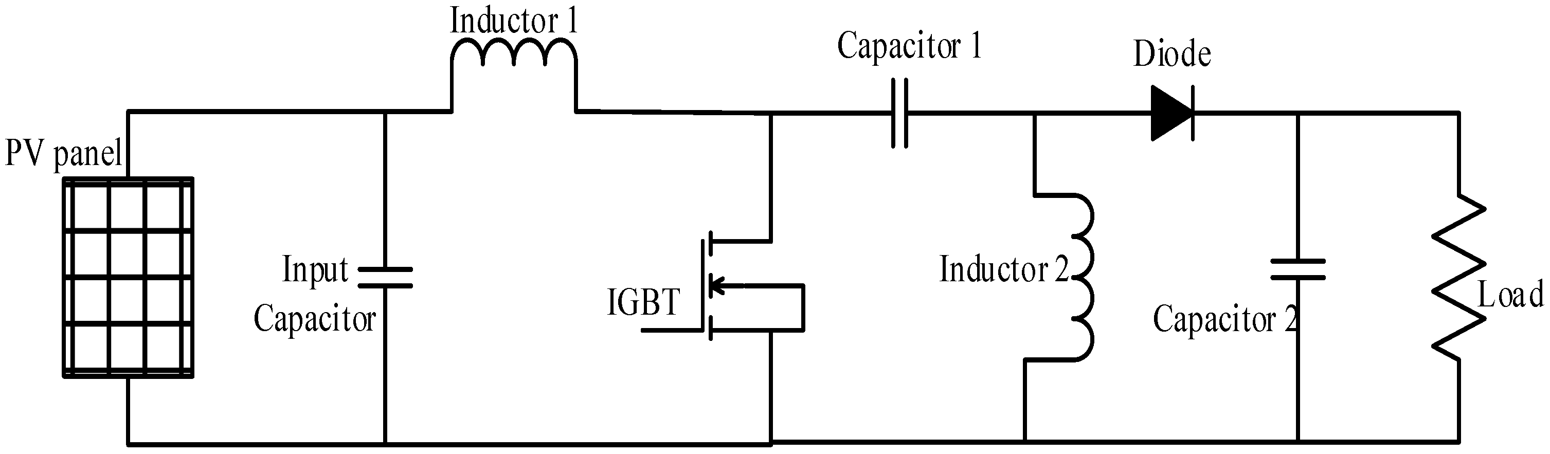
2. Proposed Photovoltaic-based SEPIC System
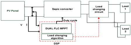
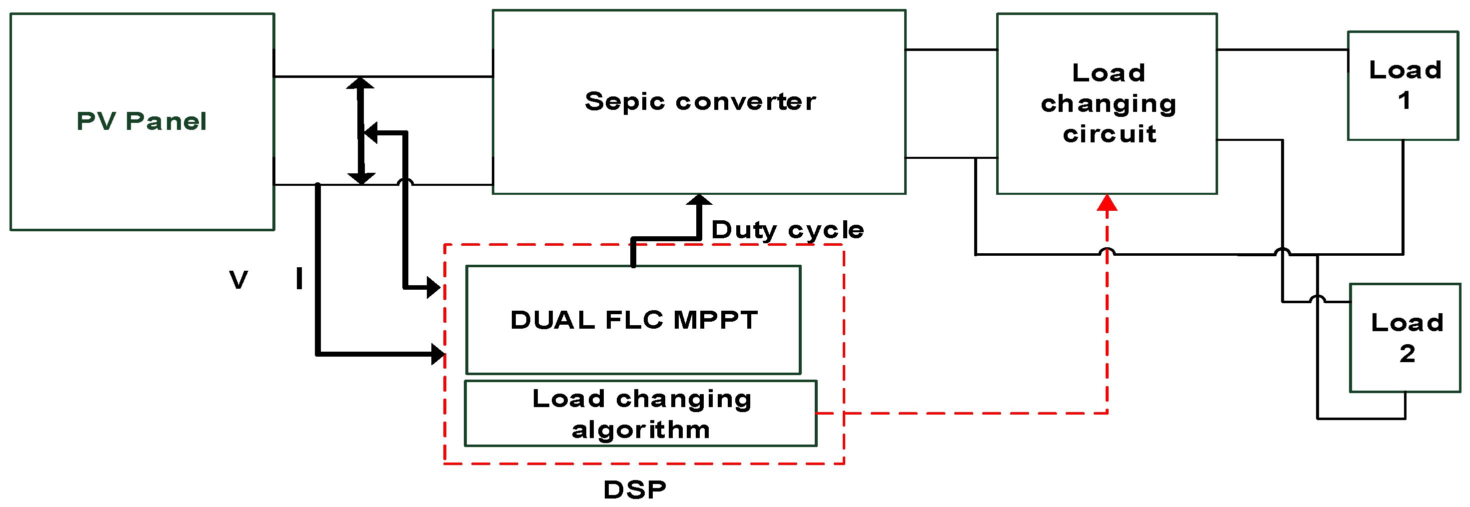
The proposed PV-based SEPIC system, as shown in
Figure 1, consists of five main parts: PV panel, SEPIC, controller which consists of dual-FLC MPPT and load changing algorithms, load changing circuit, and loads. Meanwhile,
Figure 2 presents the configuration of SEPIC. Voltage and current are measured and used by the dual-FLC MPPT to produce a suitable duty cycle to operate IGBT in SEPIC.
The voltage conversion ratio of SEPIC can be defined as follows:
where
Vout and
Vin are the output and input voltages of SEPIC, respectively, and
D is the duty cycle which is defined as the ratio of the turn-on duration to the switching time period.
Two separate loads are connected through a load changing circuit, considering one load is specifically used for buck operation and another one for boost operation. Critical performance during the switching period between buck and boost operations can be investigated later. A threshold current is set as 3 A for the load changing algorithm. If the current is less than the threshold value, the circuit will connect SEPIC to load 1. Once the input current is more than the threshold value, the circuit will connect SEPIC to load 2. When irradiance is low, the current delivered from the PV panel will be lower and SEPIC performs boost operation with FLC 1. When the irradiance is higher, the input current from the PV panel will increase, so SEPIC will perform buck operation with FLC 2.
3. Dual-Fuzzy Logic Controller Maximum Power Point Tracking
As mentioned, two FLCs are used as MPPT in this system to perform buck and boost operations, respectively. The same two inputs (error
E and change of error
CE) at sample time k are used, which are defined as below:
where
E is the change of PV power over the change of PV voltage, and
CE is the difference between the current
E from the previous
E at a given sample time.
Basically, the operation of FLC can be classified into four main elements: fuzzification, rule base, inference engine and defuzzification [
13,
14,
15,
16,
17]. During fuzzification, the inputs of the FLC,
CE and
E variables are calculated and converted into linguistic variables based on the membership functions. The output (in this case it is the duty cycle D) is generated by looking up in a rule base table [
18]. The fuzzy output is converted back to a numerical variable from a linguistic variable during defuzzification [
19,
20,
21,
22,
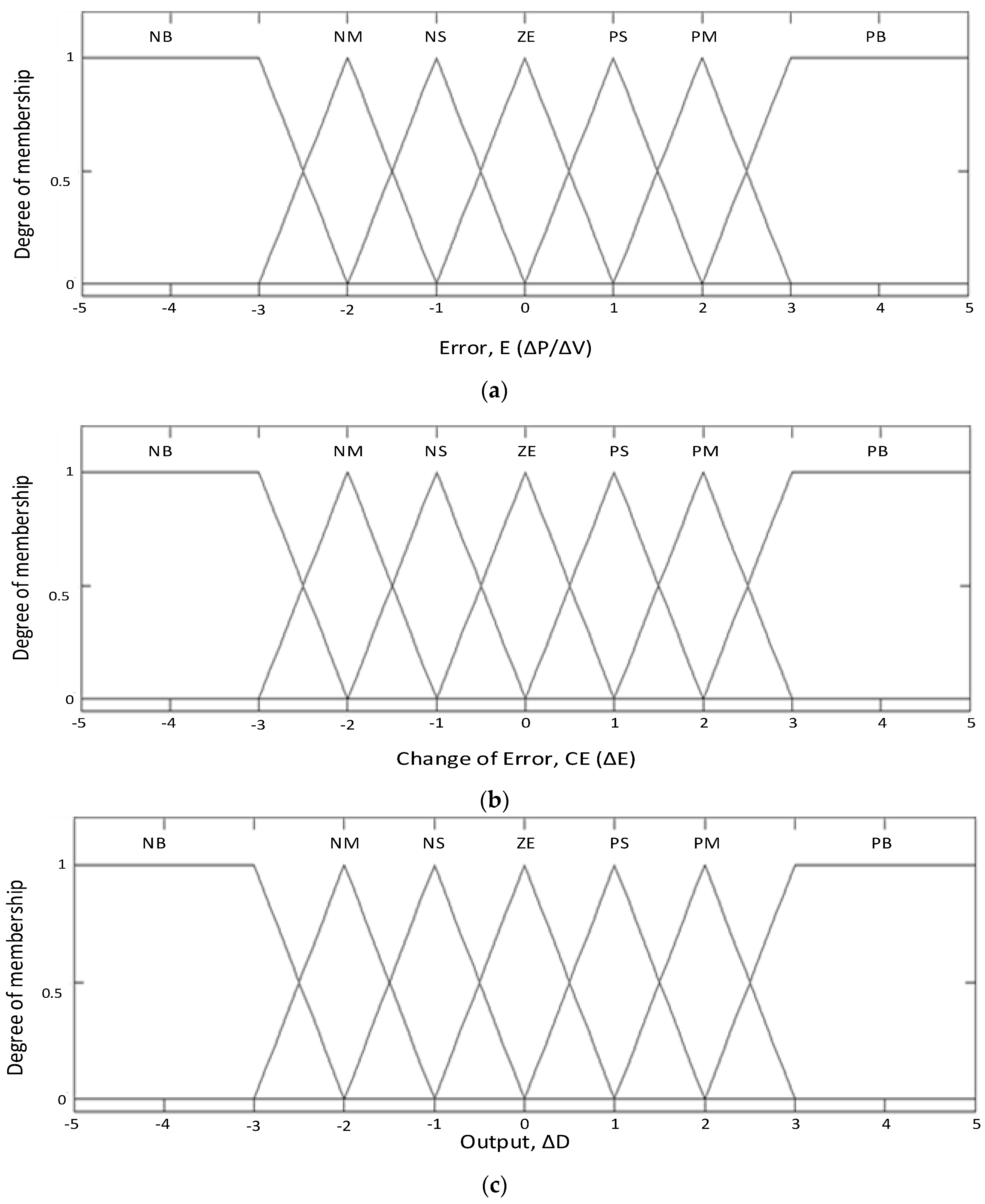
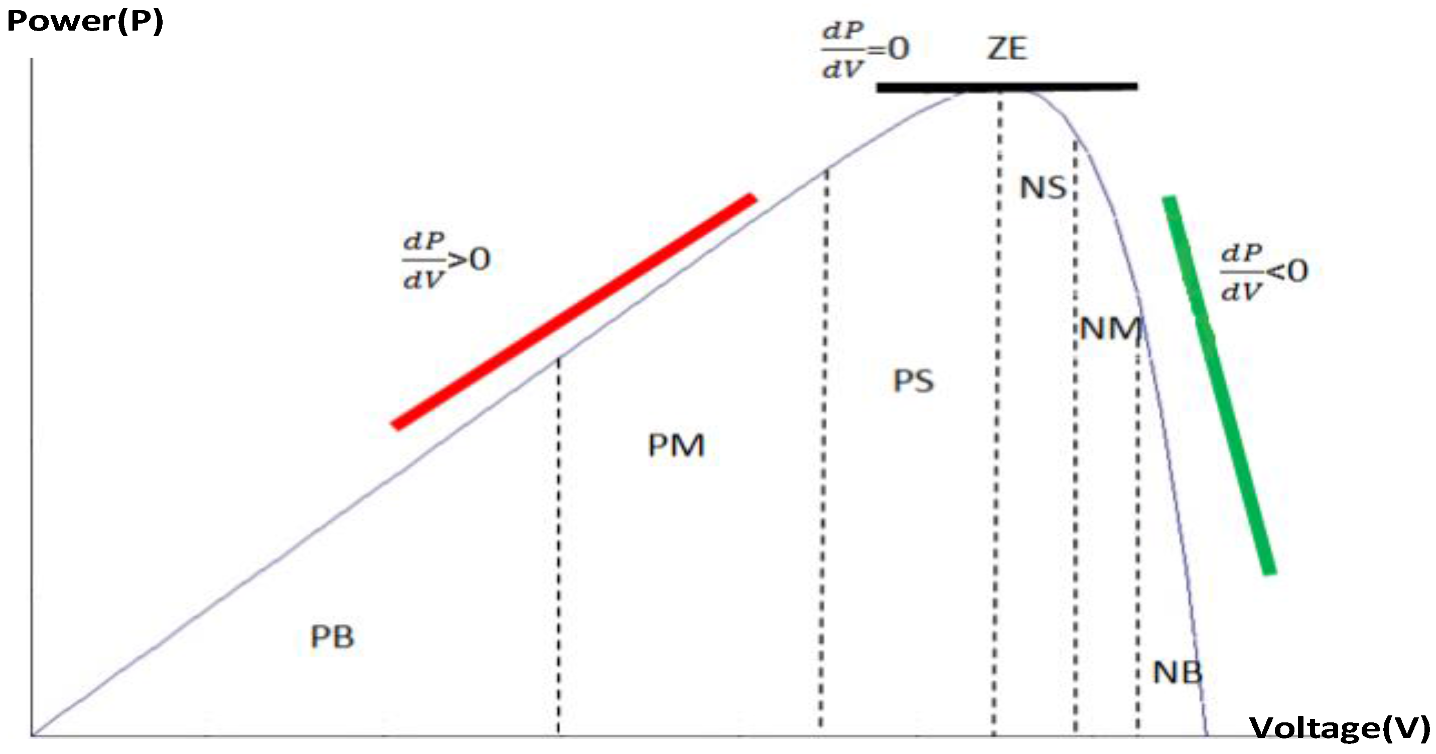
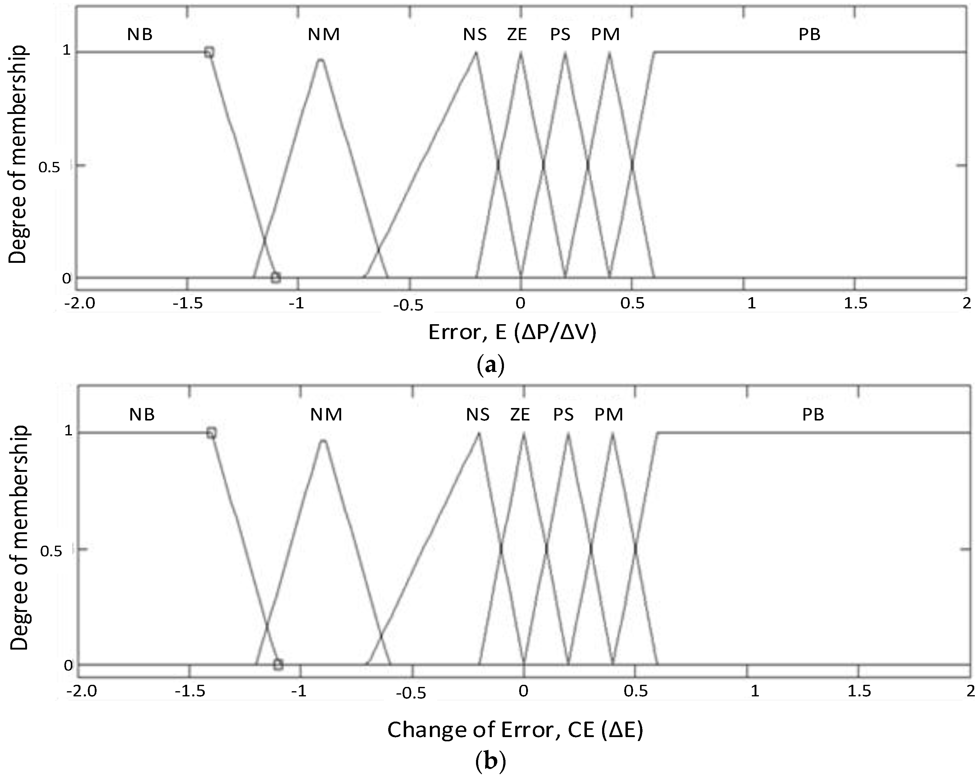
23]. The design of both FLCs differs in their patterns and ranges, as to reflect effectiveness of buck and boost operations, respectively. The concept of designing them is based on the PV curve, and the mapping of membership functions in the PV curve for the proposed MPPT is shown in
Figure 3.
The PV curve has been divided into seven segments with each representing different membership functions in the dual-FLC MPPT. The seven membership functions are Negative Big (NB), Negative Medium (NM), Negative Small (NS), Zero (ZE), Positive Small (PS), Positive Medium (PM) and Positive Big (PB). ZE membership function is located exactly at the maximum power point of the PV curve. The membership functions of the left hand side of ZE (PS, PM, PB), will be labelled as positive polarity as the gradient of the PV curve is positive, and the membership functions of the right hand side of ZE (NS, NM, NB) will be labelled as negative polarity as the gradient of the PV curve is negative. The areas of PS and NS for both polarities, in which the controller becomes more sensitive towards ZE which determines duty cycle of the controller, are critical.
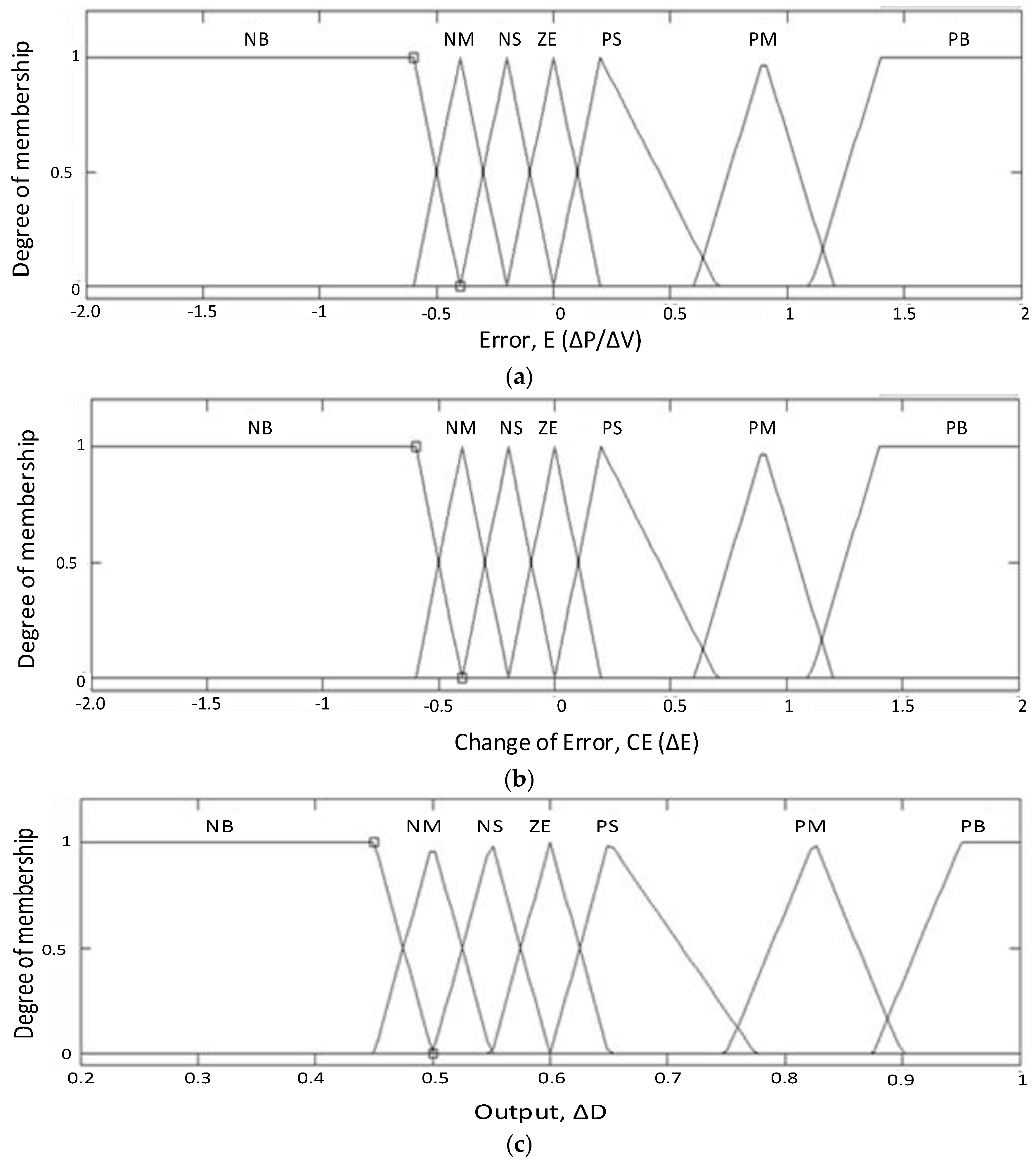
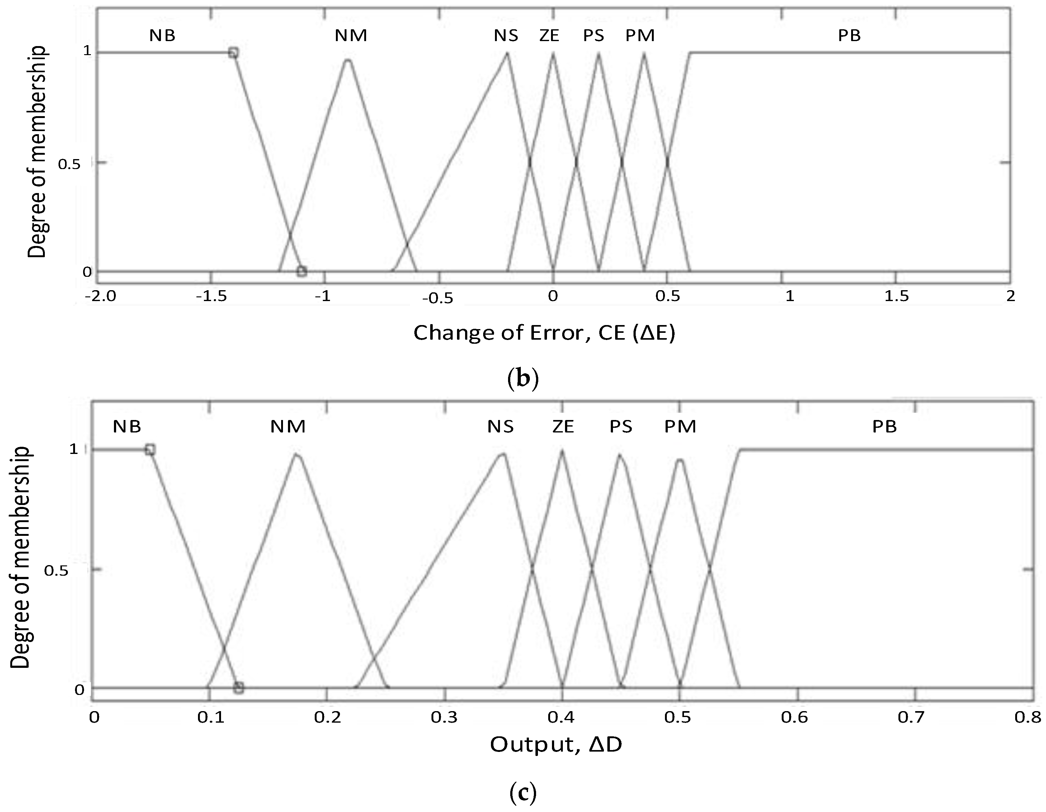
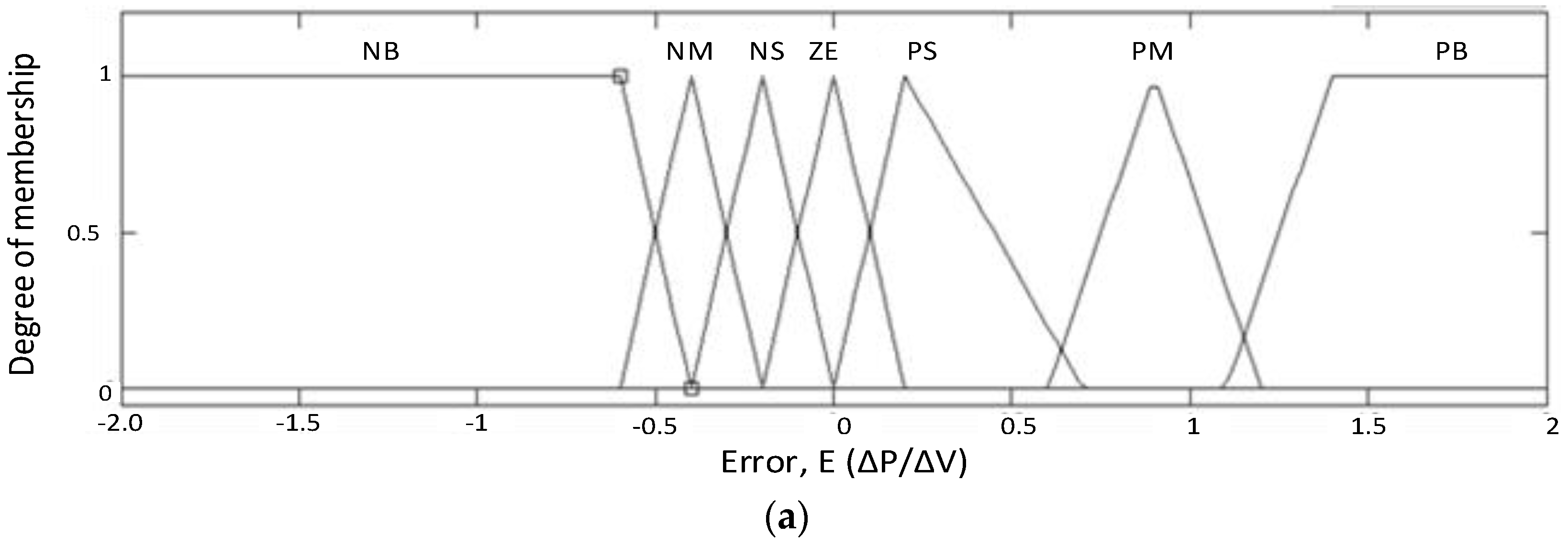
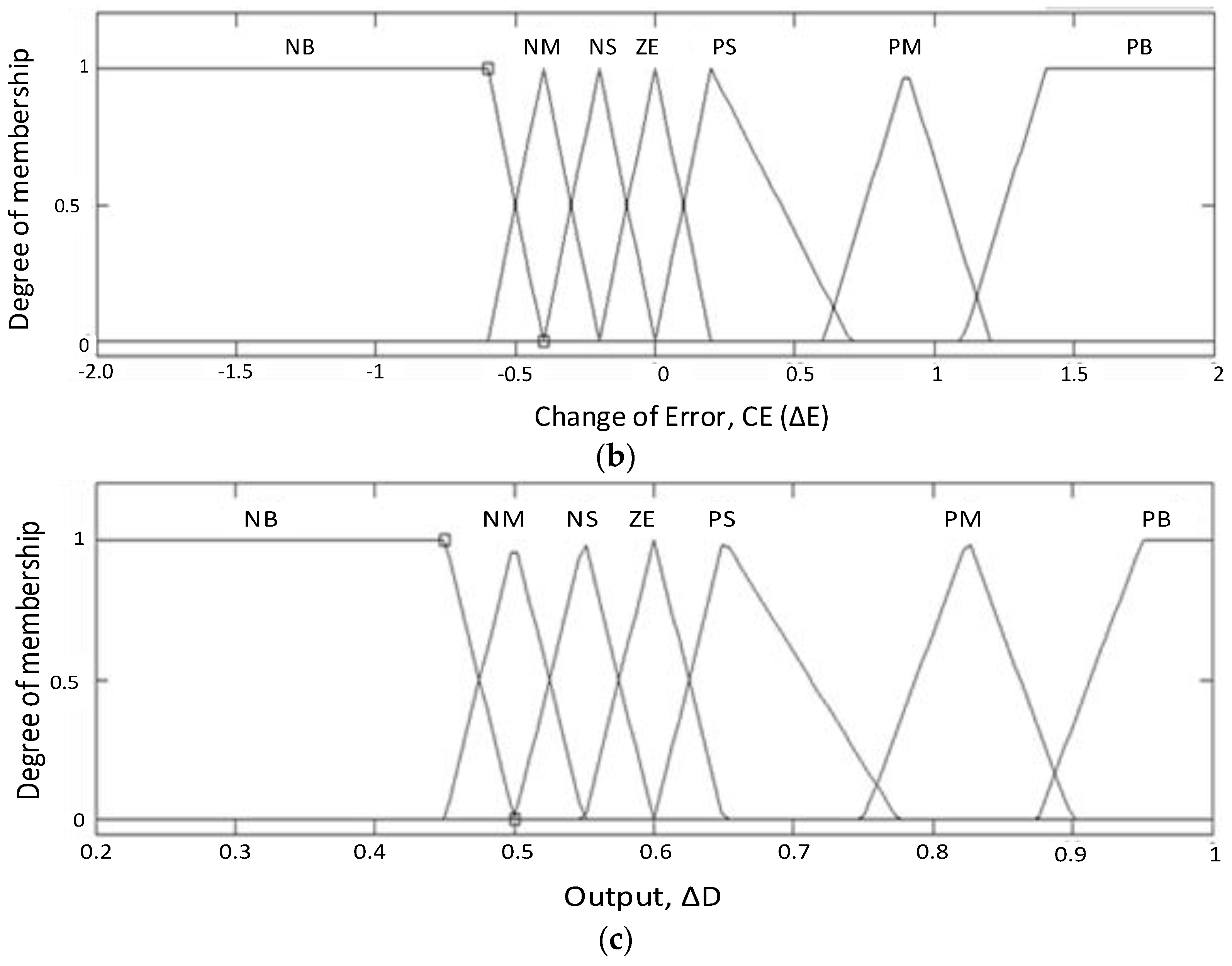
As mentioned, the design of membership functions for both FLCs is different, as shown in
Figure 4 and
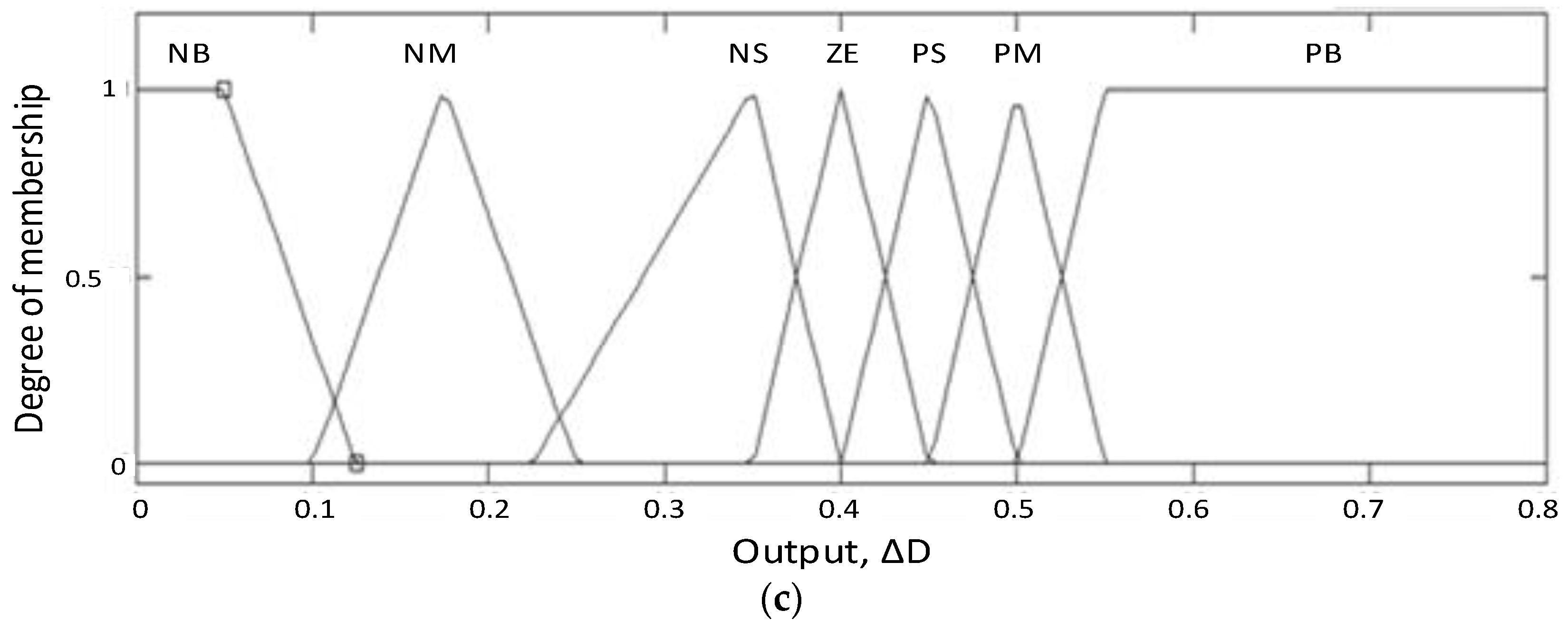
Figure 5, respectively. FLC 1 is specially designed to overcome undershoot voltage problems and FLC 2 is specially designed to overcome overshoot voltage problems. In each FLC, seven membership functions are configured for all inputs and output. All the membership functions are set as triangular shapes with both ending sides of the universe of disclosure accompanied by a trapezium shape to show continuous operation of the controller. The selected fuzzy method is Mamdani where the maximum of the minimum composition technique for the inference is used. The center-of-gravity method is used in the defuzzification process.
In FLC 1, the negative polarity membership functions such as NB, NM and NS are arranged closely to ZE so that the right hand side of the PV curve is given more priority because the selected area covered under the curve has higher voltage and this could compensate the undershoot voltage. Meanwhile, in FLC 2, the positive polarity membership functions such as PB, PM and PS are arranged closely to ZE so that the left hand side of the PV curve is given more priority because the selected area covered under the curve has lesser voltage and this could reduce the overshoot voltage. Switching signals generated by SEPIC are based on direct duty, so as to overcome the limitation of the single FLC mentioned early. However, an initial D has separately been set for FLC 1 and FLC 2 patterns respectively for preventing the output voltage to have unwanted overshoot or undershoot which could harm the system.
Table 1 shows the 49 rules for both FLCs.
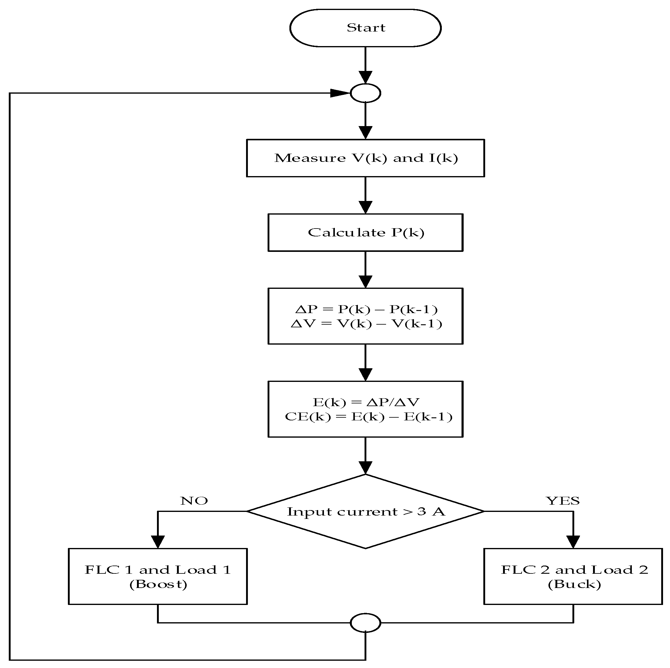
Finally, full operation of the controller is shown in
Figure 6. After measuring the PV voltage and current, power will be calculated. Then, changes of PV power and voltage are calculated. After that, error E and change of error
CE are determined for later use as inputs for the selected FLC. Meanwhile, FLC and load must be chosen, and this process considers measurement of input current. As mentioned, when the input current is lower than the threshold value (which is 3 A) due to low irradiance level, FLC 1 and load 1 will be selected. However, when the input current is higher than threshold value, FLC 2 and load 2 will be selected.
4. Simulation Results
The proposed PV-based SEPIC system was first modeled in MATLAB/Simulink. In this work, the selected PV panel is a polycrystalline silicon type that produces 210 W at 1000 W/m
2 (KD210GH-2PU, Kyocera, Esslingen, Germany). The main parameters of the selected PV panel have been tabulated in
Table 2. Meanwhile, the main components and parameters of SEPIC are shown in
Table 3.
For boost operation, the initial duty cycle is set to 0.6 with output voltage will be 39.9 V, and the output voltage will be stepped down to 17.7 V in buck operation with duty cycle of 0.4. The lower and higher irradiances are set to 200 W/m2 and 700 W/m2., and from both irradiances, the expected currents produced by the PV system are 1.2 A and 5.63 A.
For purpose of comparative evaluation, a single-FLC MPPT has been developed too [
21]. The membership functions of the single FLC are shown in
Figure 7. The membership functions must equally be arranged, as to address both buck and boost functions. As mentioned, its output is changed by duty cycle to be added later with the pre-defined duty cycle.
To further consolidate the contribution of this paper, Dual FLC has been compared with another two more single FLCs with the same number of membership functions, Single FLC 1 and Single FLC 2 MPPT that have different membership function patterns. Single FLC 1 has membership functions patterned similar to FLC 1 as in
Figure 4, while Single FLC 2 has membership functions similar to FLC 2 as in
Figure 5. The design of Single FLC 1 and Single FLC 2 is shown in
Figure 8 and
Figure 9 respectively.
The simulation work initially considers measurement and analysis at PV input due to effect of changed irradiance levels. In addition, performance of output voltages for both loads has been analyzed by undergoing switching operation by load changing circuit. The waveforms have been captured, and performance of the dual-FLC MPPT is compared with the single-FLC MPPT, by considering parameters such as response time and power loss, both during transient part.
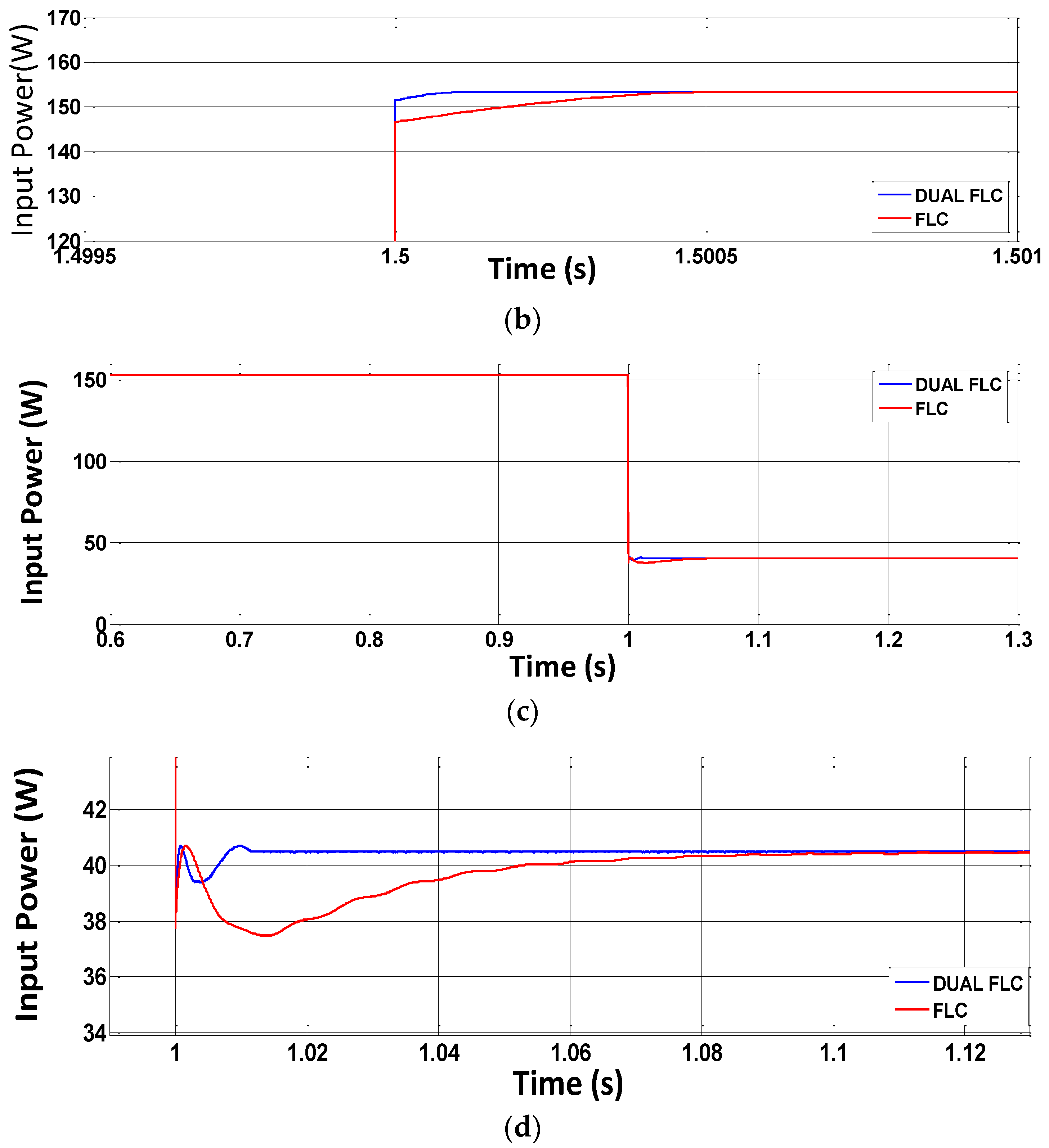
Figure 10 shows waveforms of input powers for both buck and boost operations. During buck operation, both MPPTs manage to control SEPIC to achieve maximum power as expected at 155 W. However, during transient part, the proposed MPPT performs much better with response time only 0.1 ms to achieve steady state as compared to the single-FLC MPPT with 0.4 ms. Consequently, lower energy loss obtained by the dual-FLC MPPT with only 2.5 µJ as compared to the single-FLC MPPT with 4.2 µJ. Interestingly, big difference between both MPPTs can be seen during boost operation. While the dual-FLC MPPT only needs 12 ms to achieve steady state (energy loss of 4.8 mJ), the single-FLC MPPT contributes to bigger energy loss (up to 210 mJ) due to longer response time (100 ms).
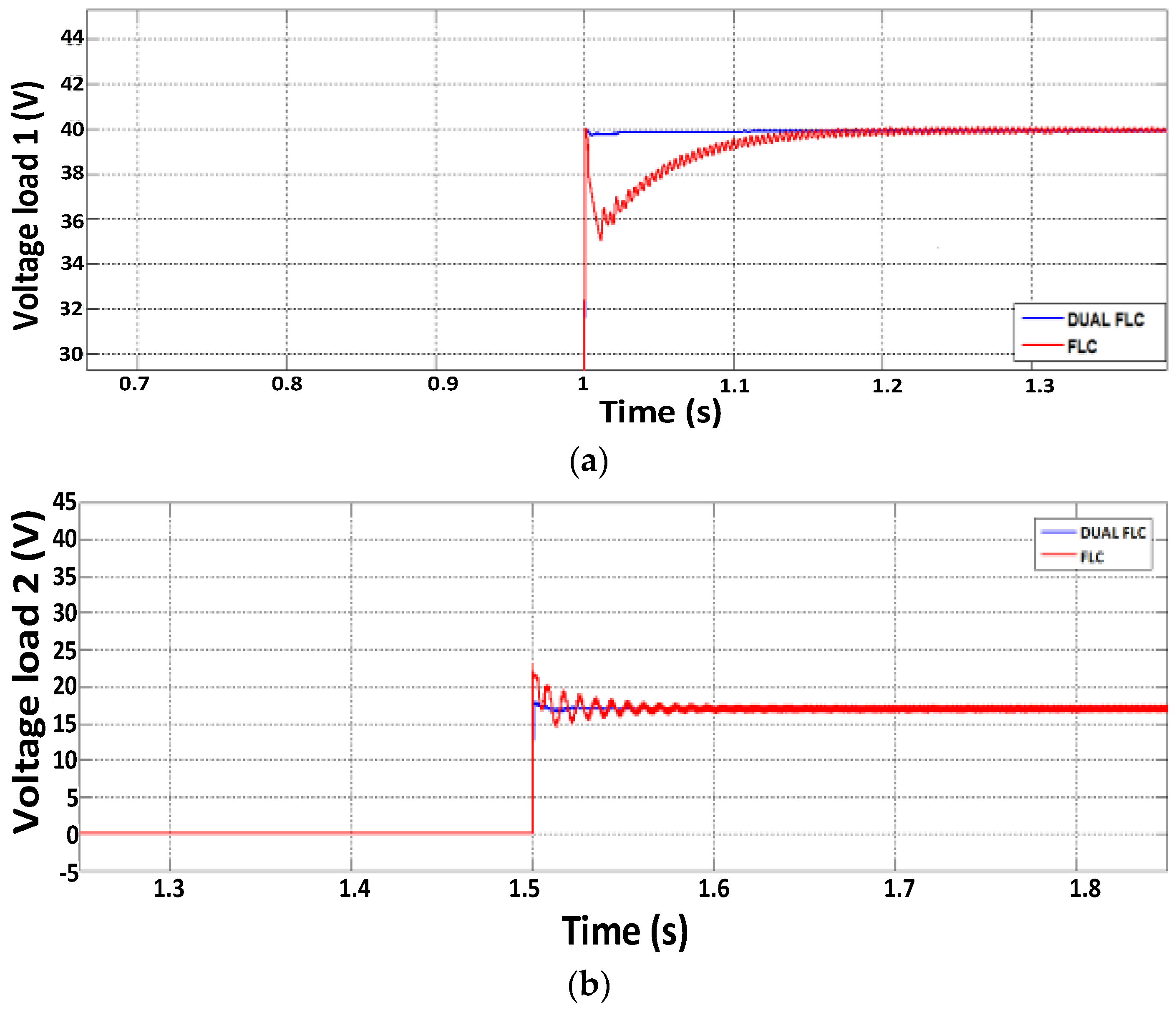
Figure 11 shows output voltages at both loads 1 and 2 during buck and boost operations, respectively. During buck operation with high irradiance, there will be voltage overshoot with smaller value (0.1 V) achieved by the dual-FLC MPPT as compared to the single-FLC MPPT (3.2 V). Furthermore, no such oscillation occurs with the dual-FLC MPPT, while the single-FLC MPPT shows some oscillations before reaching steady state. The negligible oscillation confirms the effectiveness of using direct duty cycle by the dual-FLC MPPT. During boost operation when irradiance is low, negligible undershoot with faster response time (less than 0.04 s) is achieved by the dual-FLC MPPT; whereas the single-FLC MPPT causes a longer time for the load 2 to achieve a stable output voltage with a response time of up to 0.17 s, with an undershoot voltage of 4.2 V. Therefore, from all simulation results, clearly the dual-FLC MPPT shows better performance, with negligible oscillation, small overshoot, fast response time, and negligible undershoot.
5. Experimental Results
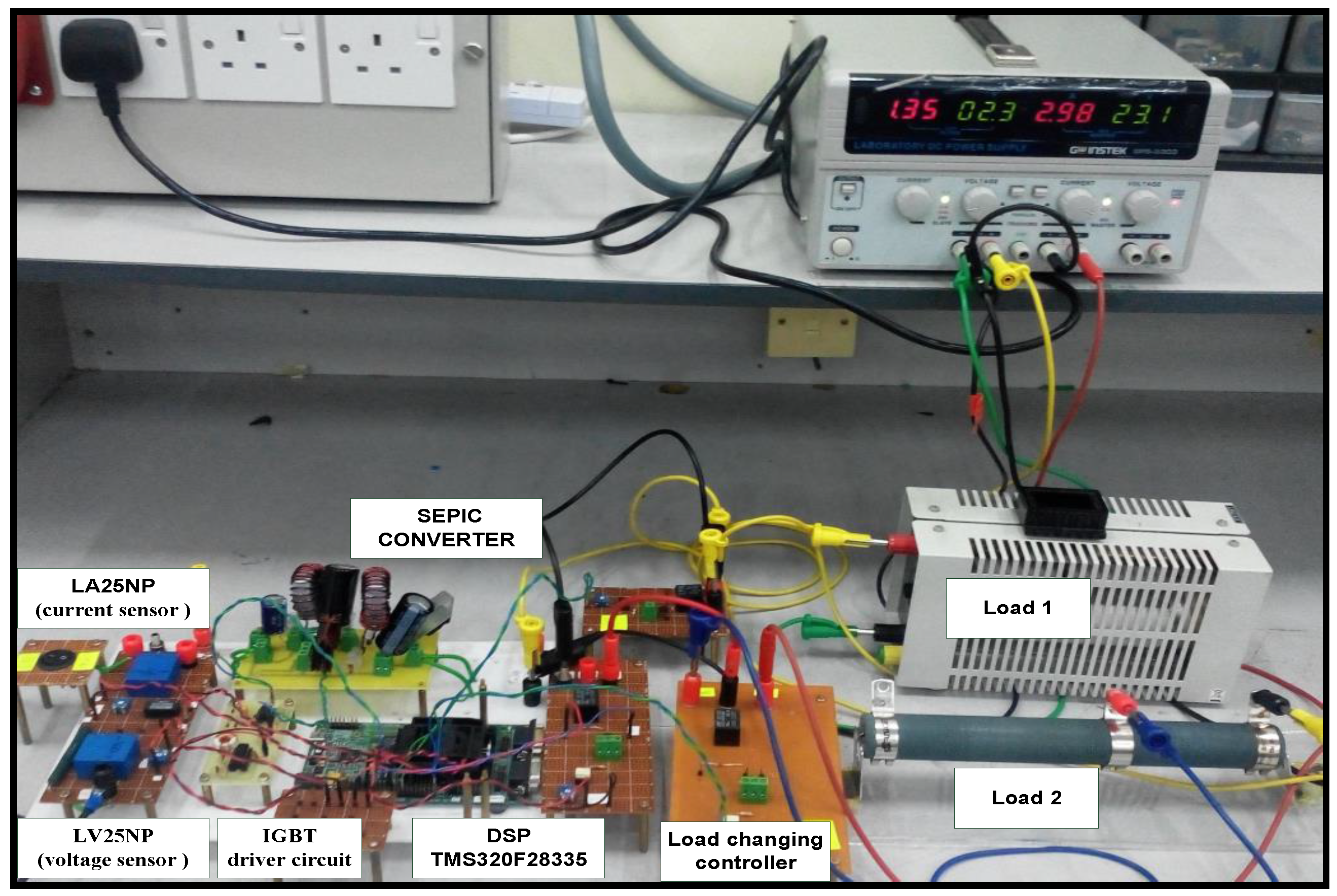
A laboratory prototype of the PV-based SEPIC system was developed as shown in
Figure 12, with same parameters to investigate performance of the dual-FLC MPPT. A Chroma Programmable DC Power Supply 62100H-600S (600 V/25 A/15 kW, Chroma ATE Inc., Taoyuan, Taiwan) with Solar Array Simulation is used as solar simulator. The dual-FLC MPPT as the proposed algorithm, and also the single-FLC MPPT for comparison purpose, are implemented in a TMS320F28335 eZdsp board (Texas Instruments, Dallas, TX, USA). The same waveforms and parameters as defined in the simulation work are used. The measured and calculated parameters obtained for all simulation results and experimental results are summarized in
Table 4.
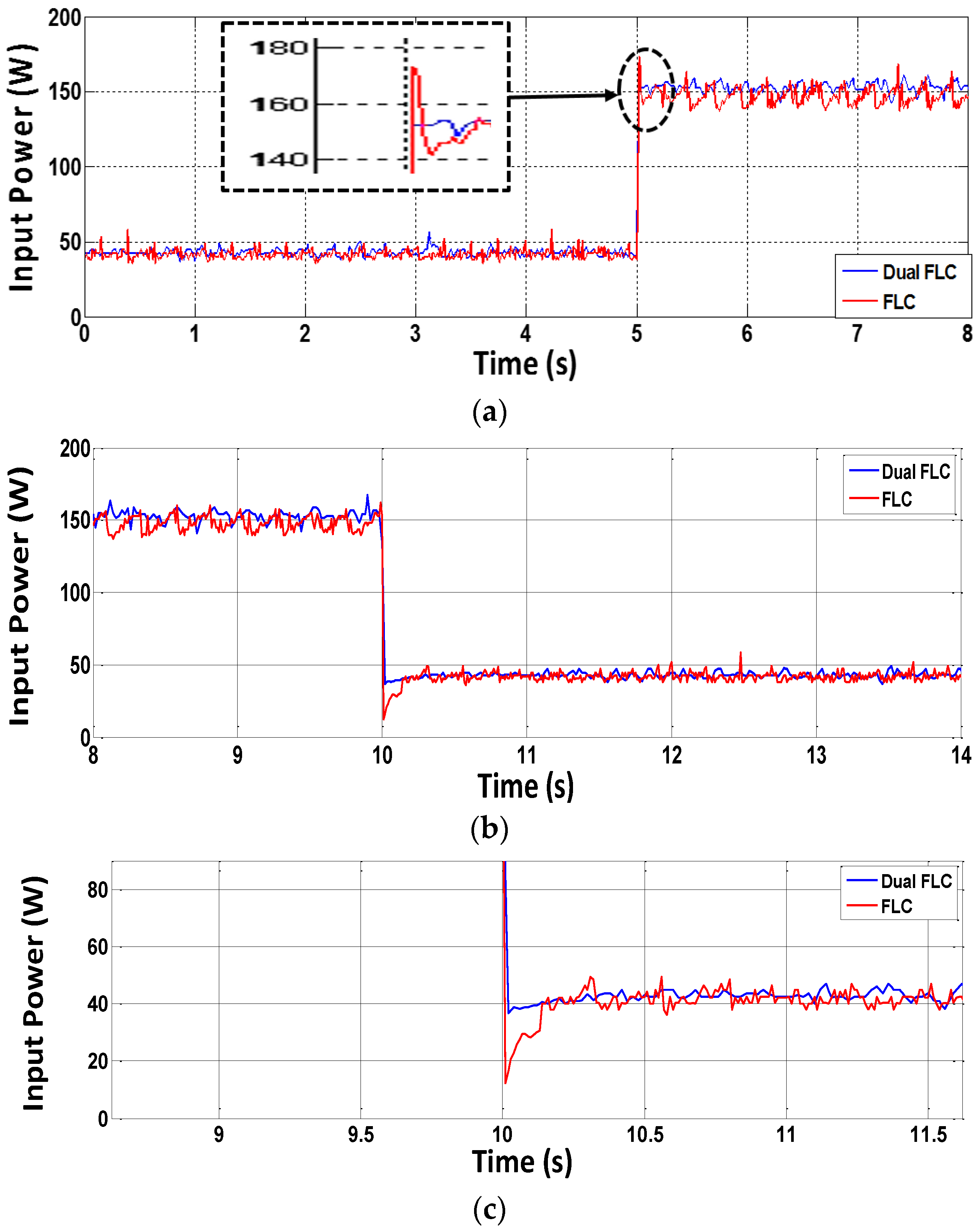
Figure 13 shows waveforms of input powers for both buck and boost operations. During buck operation, like in the simulation work, the dual-FLC MPPT performs better with a response time of 0.01 s as compared to the single-FLC MPPT with 0.2 s. Reduction of energy loss is obtained by the dual-FLC MPPT (only 4 mJ) as compared to the single-FLC MPPT with 860 mJ. During boost, a significant impact of implementing the dual-FLC MPPT is shown, with only 0.02 s needed to achieve steady state (lower energy loss of 19 mJ), while the single-FLC MPPT causes a bigger energy loss (up to 293 mJ) due to the longer response time (0.26 s).
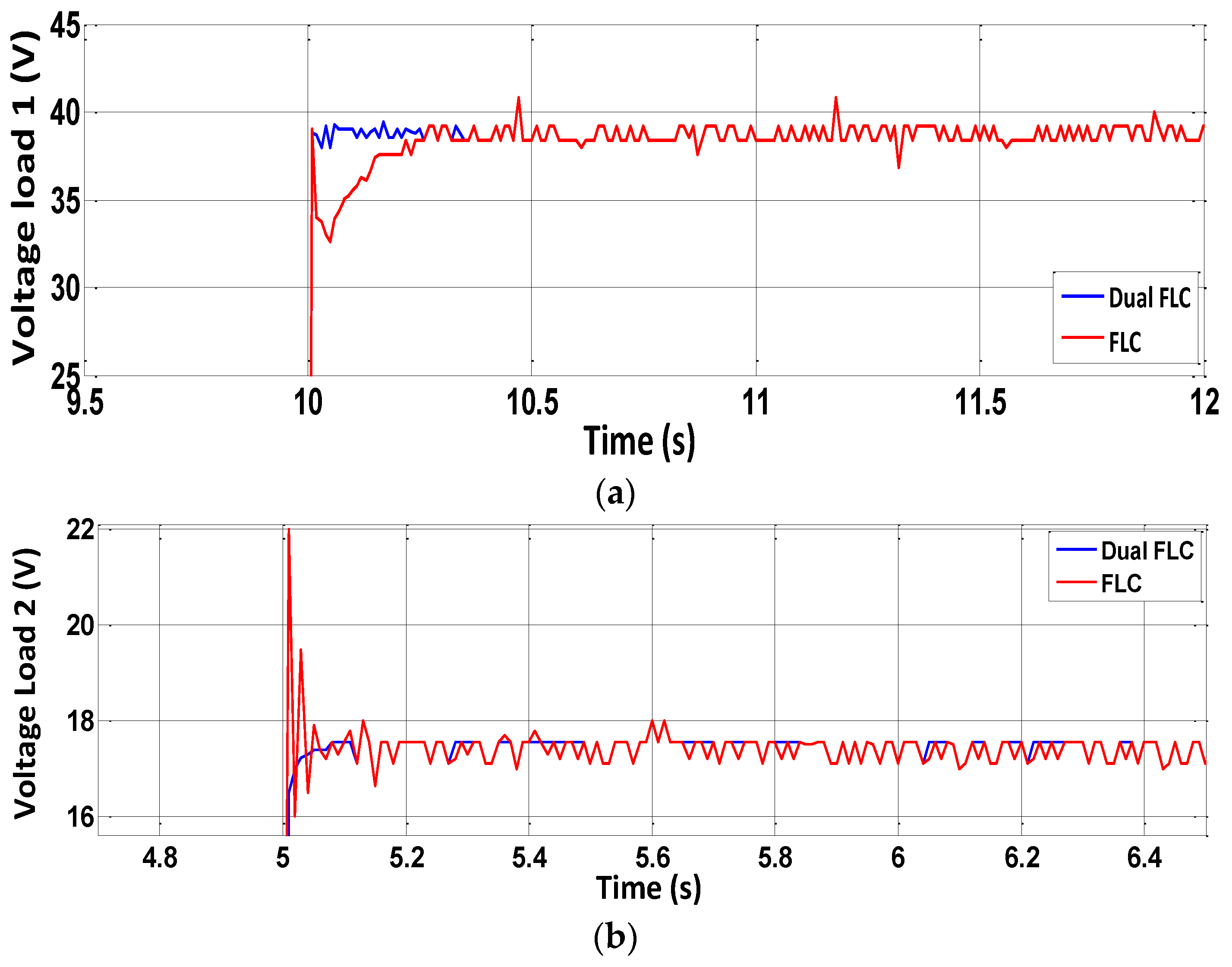
Figure 14 shows output voltages at both loads 1 and 2 during buck and boost operations, respectively. During buck operation, there will be no overshoot voltage with the dual-FLC MPPT as compared to the single-FLC MPPT (5.3 V). During boost operation, lower undershoot with faster response time (less than 0.01 s) is achieved by the dual-FLC MPPT; however, the single-FLC MPPT takes longer (a response time of up to 0.3 s) for load 2 to obtain a stable output voltage. All experimental results confirm the effectiveness of the dual-FLC MPPT in SEPIC operation to step down and up voltage accordingly.
Changing the single-FLC MPPT to single-FLC 1 MPPT and single-FLC 2 MPPT, the performance of the MPPTs has been evaluated and this case study is rather important to justify the selection of the membership function pattern when applying FLC MPPT.
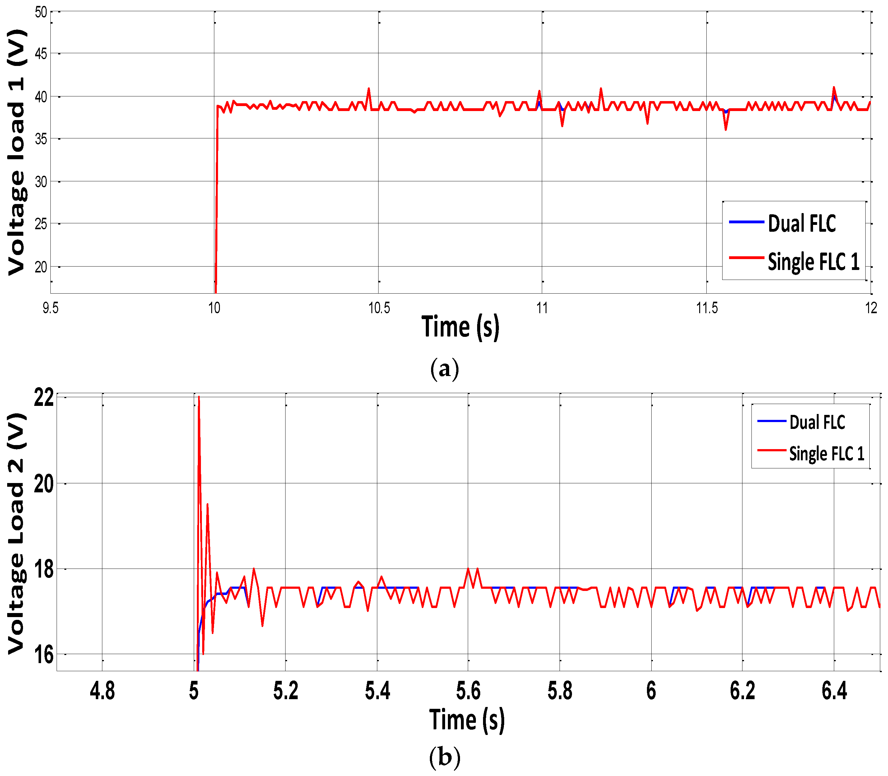
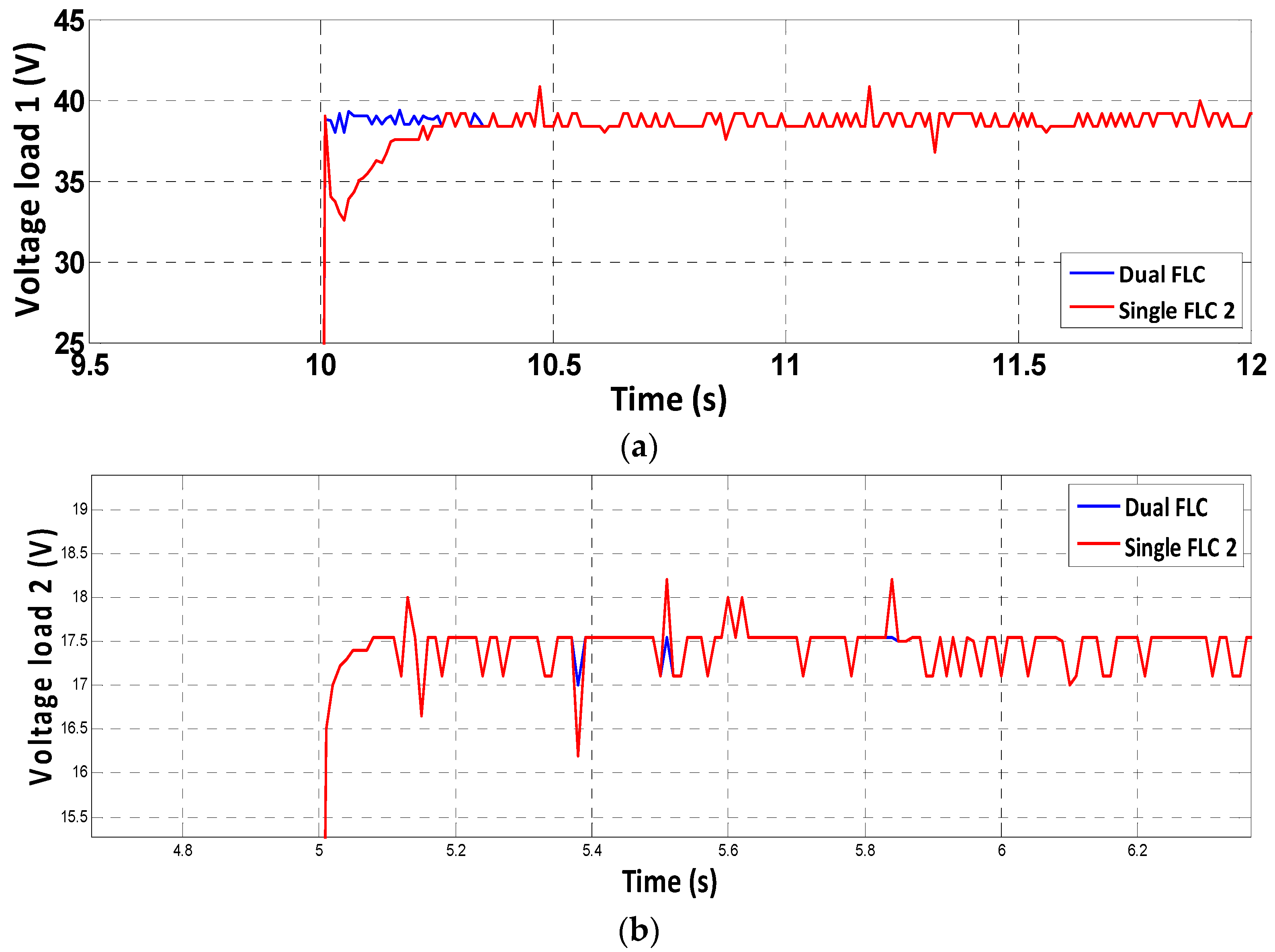
Figure 15 shows the output voltages at both loads 1 and 2 during buck and boost operations by comparing the performance of single-FLC 1 with dual FLC MPPT. During boost operation, the performance of both single-FLC 1 MPPT and dual-FLC MPPT are the same due to their similar membership function patterns. During buck operation, there will be no overshoot voltage with the dual-FLC MPPT as compared to the single-FLC 1 MPPT (5.3 V). By using single-FLC 1, there is no undershoot voltage during boost operation but overshoot voltage still exists during buck operation.
Figure 16 shows output voltages at both loads 1 and 2 during buck and boost operations by comparing the performance of single-FLC 2 with dual-FLC MPPT. During buck operation, the performance of both single-FLC 2 MPPT and dual-FLC MPPT are the same due to their similar membership function patterns. During boost operation, there will be no undershoot voltage obtained by the dual-FLC MPPT as compared to the single-FLC 2 MPPT. Single-FLC 2 MPPT also presents a greater time response of about 0.2 s. By using single-FLC 2, there is undershoot voltage during boost operation but no overshoot voltage exists during buck operation.
Table 5 presents simplified results that shows the occurrence of overshoot voltage and undershoot voltage during buck and boost condition for each MPPT algorithm and it clearly shows the need of dual FLC MPPT to buck and boost output voltage without having energy losses during the initial period.


 ,
, 


