1. Introduction
Distributed generators (DGs) have attracted considerable attention because they can improve the reliability, increase the efficiency, expand the availability, and increase the use of renewable energy sources. The microgrid concept integrates several DGs into a single small-scale electrical network. It is considered an effective means of maximizing the benefits of DGs [
1]. Microgrids integrate DGs, energy storage systems (ESSs), electrical loads, and so on [
2]. Moreover, they can be connected to existing grids so that contentious uninterruptible power can be independently supplied to a local load when the grid fails. Furthermore, unlike existing commercial grids, generation and transmission simultaneously occur in a distribution system. Accordingly, they comprise an effective and innovative way of improving system efficiency [
3]. Thus, there have been continuous attempts to commercialize the microgrid [
4].
Depending on the state of the connection between the microgrid and utility grid, the microgrid can be in grid-connected mode or islanded mode. In grid-connected mode, the microgrid responds to the demand management of the upper energy management system (EMS). Accordingly, each DG in the microgrid participates in reducing the peak load and energy costs of the entire electrical power system. Microgrids can also contribute to various forms of policy-based energy management through a real-time electrical information network. In this way, they are becoming an important technology that is changing the existing electrical market paradigm [
5].
When a failure occurs in an existing commercial grid, the microgrid converts to islanded mode, which is electrically separated from the upper grid, to provide high quality uninterrupted power to a local load. At that point, the microgrid becomes a single, complete, independent electrical network. In islanded mode, the local EMS manages the local power quality, monitors the electrical power flow, and controls the DGs. The power quality of the local microgrid in islanded mode is determined by the DG with the largest capacity. An inverter-based battery system typically controls the local microgrid’s voltage and frequency in a distributed [
6], centralized [
7], and autonomous [
8] manner. Additionally, the ESS-like battery or super capacitor can stabilize the local power system in a short period of time with the use of power electronic converters [
9].
With recent rapid advances in power electronics technology, photovoltaic and wind turbine power generation systems have become the primary distributed generators in microgrids. However, these generators experience severe short-term output fluctuations, which make connection to an ESS necessary because it can act as an energy buffer for these output fluctuations [
10]. Parallel uninterruptable power supply (UPS) control technologies have been expanded [
11]. These connect various distributed generators to the ESS, and can be roughly divided into three categories: methods that use high-speed data communication [
12], methods that use low-speed data communication [
13,
14], and methods that do not employ communication [
15]. Methods that use high-speed data communication are limited, however, because communication speed determines the system performance, and communication errors can quickly cause system failures. Furthermore, high-speed data links have physical limitations relating to distance.
Other methods have been used for load sharing between each generator and ESS, including a technique that avoids high-speed data links by using electrical line communications [
16], as well as a method that sends signals through the DC bus. However, these methods have drawbacks in that they are inherently vulnerable to noise, and it is thus difficult to set the signal’s bandwidth. Consequently, methods have been proposed that use no communication between generators; rather, each generator system employs only its own connection point voltage information to self-regulate [
17].
Autonomous control methods based on these existing droop methods exist [
18]. In these methods, DGs use a line impedance model to regulate the generator output voltage frequency and magnitude to control active/reactive power transmission [
19,
20]. However, while existing large synchronous generators have high rotor inertias, each generator in an inverter-based microgrid is a very low inertia system. Therefore, system poles are placed near the imaginary axis [
21]. Because line impedance is very small, it is good for blocking current and performing failure diagnostics. Nevertheless, it has the shortcoming of making it very difficult to maintain a standard level of power quality. A significant amount of research on the long transient state and excessive reactive power between generators is still needed [
22].
In this paper, we analyze and experimentally verify the effect that battery inverter voltage control methods have on local power quality when DG inverters and battery inverters operate together in a microgrid in islanded mode [
23]. We focus on the structure of a normal microgrid that regulates the local microgrid’s voltage and frequency by the battery inverter. In this hybrid generator structure, the battery inverter performs the most important role of determining the local microgrid’s power quality. In this case, generally, the battery generation capacity is the largest. It is structured so that communication is performed by transmitting only the failure data of each distributed generator and battery converter at low speed.
The remainder of this paper is organized as follows: in
Section 2, microgrid control techniques are illustrated.
Section 3 describes the hybrid system configuration of an inverter-based microgrid. Two grid-forming DG control types are analyzed and compared in
Section 4. Power flow analysis in a hybrid microgrid is presented in
Section 5, and simulations and experimental results are shown in
Section 6. Finally, the conclusions are presented in
Section 7.
2. Control of Microgrid with Local Energy Storage System
To make the microgrid flexible and reliable, different DG power conditions and storage capacities of ESS must be globally considered [
15]. An energy management algorithm based on model predictive control is proposed in [
24]. Additionally, a coordinated state-of-charge (SoC)-based control strategy is derived in microgrid energy management systems to stabilize the frequency and voltage amplitude in [
25]. In these works, the coordinated operation between ESS and other DGs relies on the centralized power control with a high-speed communication link. In this case, the overall system will lose coordination when a single point failure occurs.
An advanced decentralized microgrid control algorithm is introduced in [
26]. Flexible demand participation is considered in order to achieve decentralized control coordination; however, it requires complex computation, and the system dynamics is highly dependent on the communication system.
To avoid the critical communication link, autonomous control strategies have been widely investigated. A droop control strategy has been proposed to achieve desirable active and reactive power sharing in AC microgrids [
20]. This scheme uses only local power information to detect changes in the system and adjust the operating points of the generators accordingly. However, since most energy sources are controlled in power control mode at the maximum power point, the conventional droop method is difficult to be directly implemented for power management in integrated energy sources and ESS systems.
A simple and effective microgrid control method for constructing an inverter-based microgrid without a critical communication link is adopted in this study. Distributed energy sources in a local microgrid operate in accordance with their own maximum power point tracking (MPPT) algorithm, and ESS controls the local power flow. There is no complex energy management system; moreover, a low bandwidth communication system is utilized only for monitoring and protection purposes. Islanded microgrids are now being implemented on Korean islands in this way.
3. Hybrid Configuration of Grid-Forming and Grid-Following Inverters
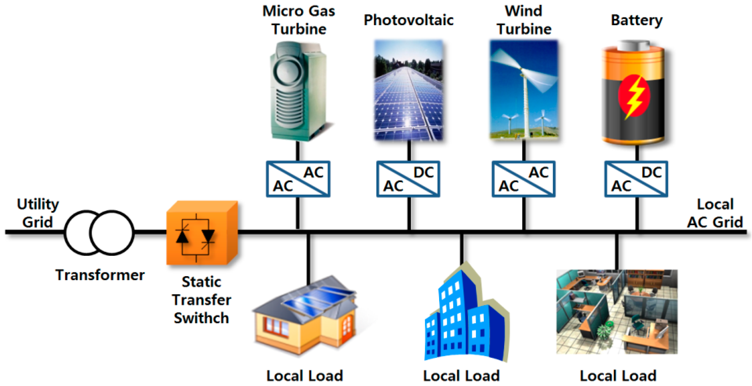
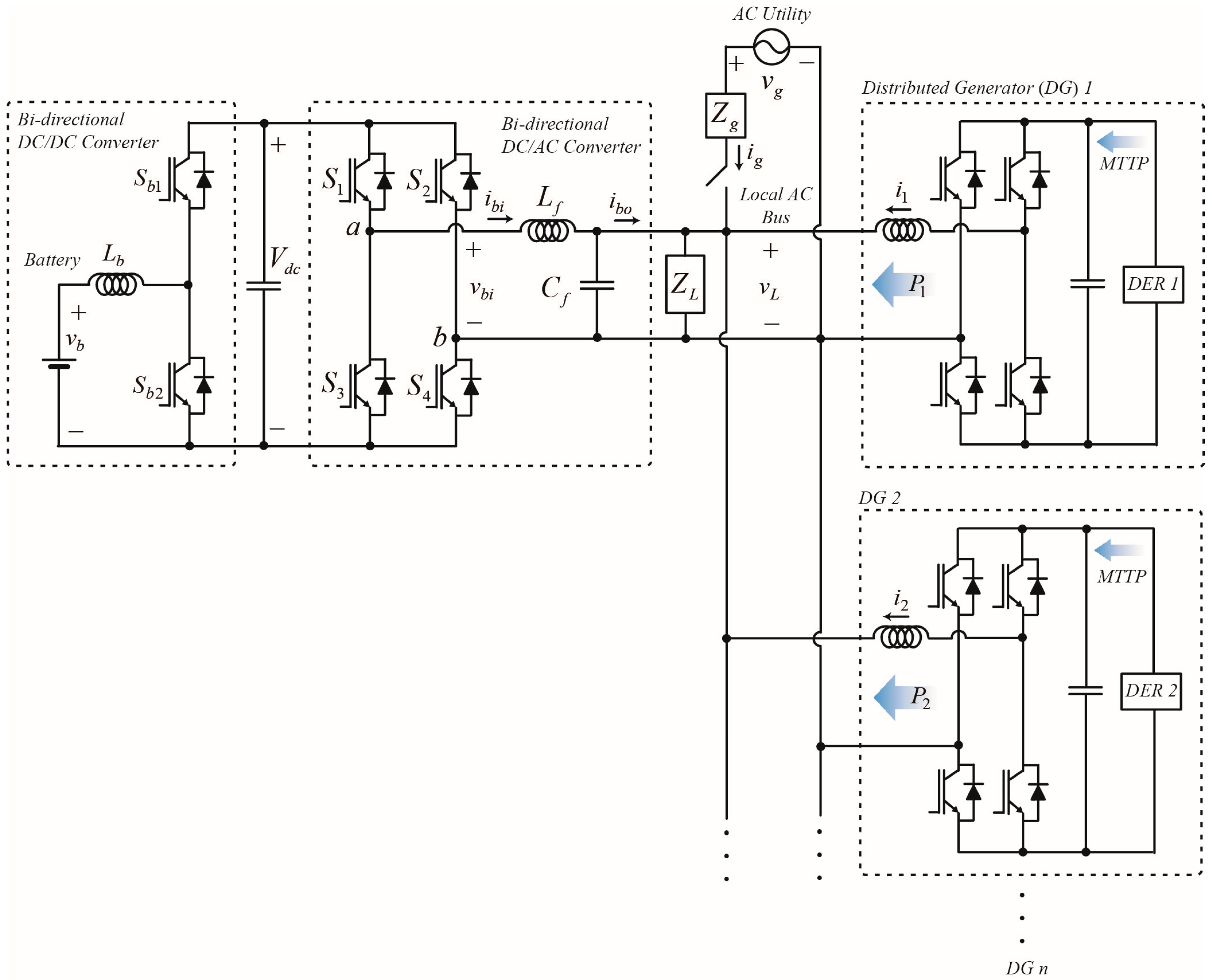
Figure 1 shows the structure of an inverter-based microgrid in which several types of distributed generators are connected to the local power bus through inverters. The microgrid can normally connect or disconnect from the upper grid through a static transfer switch (STS). The STS is controlled by the EMS or the battery power converter.
When creating a microgrid that employs renewable energy sources with severe output, a process is required for equalizing the regional grid’s entire generation output over time through ESS. In this set-up, the power converter of each ESS operates while converting the output mode according to the battery state. The methods for controlling this process are divided into respective centralized, master/slave, and autonomous controls. In the cases of centralized control and master/slave control, the control structure is simple and implementation is easy. However, a system failure may occur because control is achieved through a single control board and is dependent on high-speed data communications [
19,
27]. Control in the autonomous control method is complicated and has nonlinear, time-varying dynamic properties. Nevertheless, autonomous control is easily expandable and can be designed so the failure status of each individual generator does not affect the entire system. Accordingly, it is considered the most difficult to use but can ensure the best reliability. The inverters used in the microgrid shown in
Figure 2 usually have two operation modes. The first is called the ‘grid-following’ operation. It provides high-quality AC current, which is synchronized with the voltage of the connection point. The magnitude of the current that enters the local AC bus from each individual inverter is regulated according to the MPPT algorithm for the distributed energy resource [
23]. The second mode is called the ‘grid-forming’ operation. In this mode, the inverter regulates the local microgrid’s voltage and frequency. Unlike the grid-following operation, which is performed through the inverter’s current control, the grid-forming operation is conducted through the inverter’s voltage control.
The regulation of the local microgrid’s voltage implies several things. The inverter that regulates the voltage becomes the main generator of the local microgrid. A grid-forming inverter provides both active and reactive power. According to [
27], during grid-connected mode, the DG inverters must use the grid-following operation. During islanded operation, some or all of the DG inverters are required to use the grid-forming operation. In this study, the target is a hybrid AC microgrid system, where grid-forming inverters and grid-following inverters are connected in parallel in islanded mode.
4. Battery Inverter Voltage Control
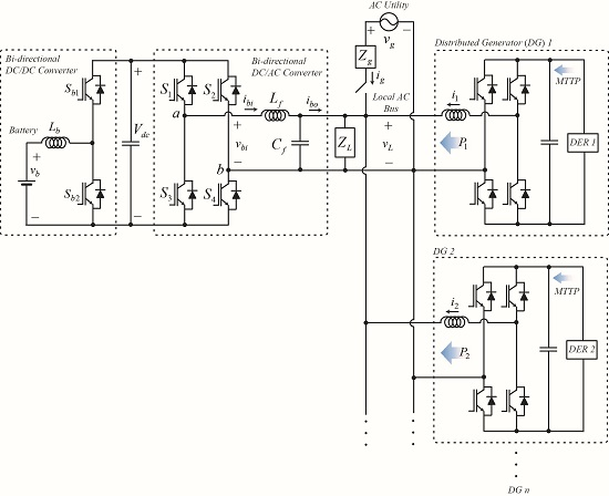
Figure 2 shows the structure of a microgrid system with battery inverters in grid-forming operation during islanded mode. Other DGs in
Figure 2 are composed of grid-following inverters (grid-connected inverters) in accordance with [
23]. Major requirements in [
23] are listed in
Table 1.
That is, all DGs except the battery system are in grid-following operation without relation to the on/off status of the STS. Therefore, the system in
Figure 2 is compatible with DGs based on the existing system described in [
23].
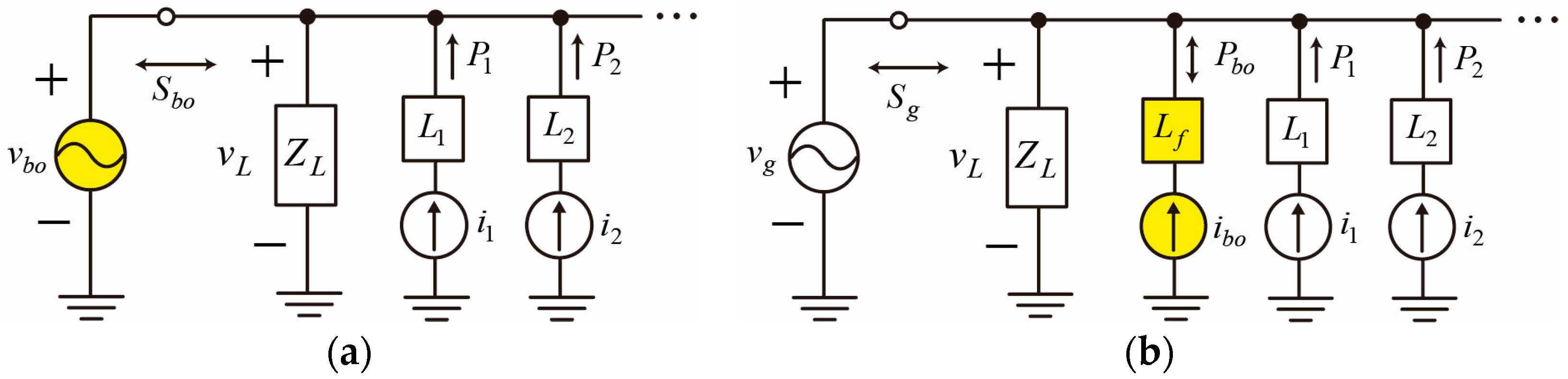
Figure 3 shows the equivalent circuits of each operation mode of the microgrid in
Figure 2. During islanded operation, the battery inverter controls the load voltage
across the filter capacitor
for the grid-forming operation. It thus becomes an equivalent voltage source, as shown in
Figure 3a. The remaining DGs use the grid-following operation and become equivalent current sources.
On the other hand, during grid-connected mode, the grid becomes the main voltage source, and the battery inverter converts to grid-following mode. All DGs thus become equivalent current sources, as in
Figure 3b. In the microgrid’s grid-connected mode, the battery power converter follows the existing, normal grid-following control method; hence, control is very simple [
23].
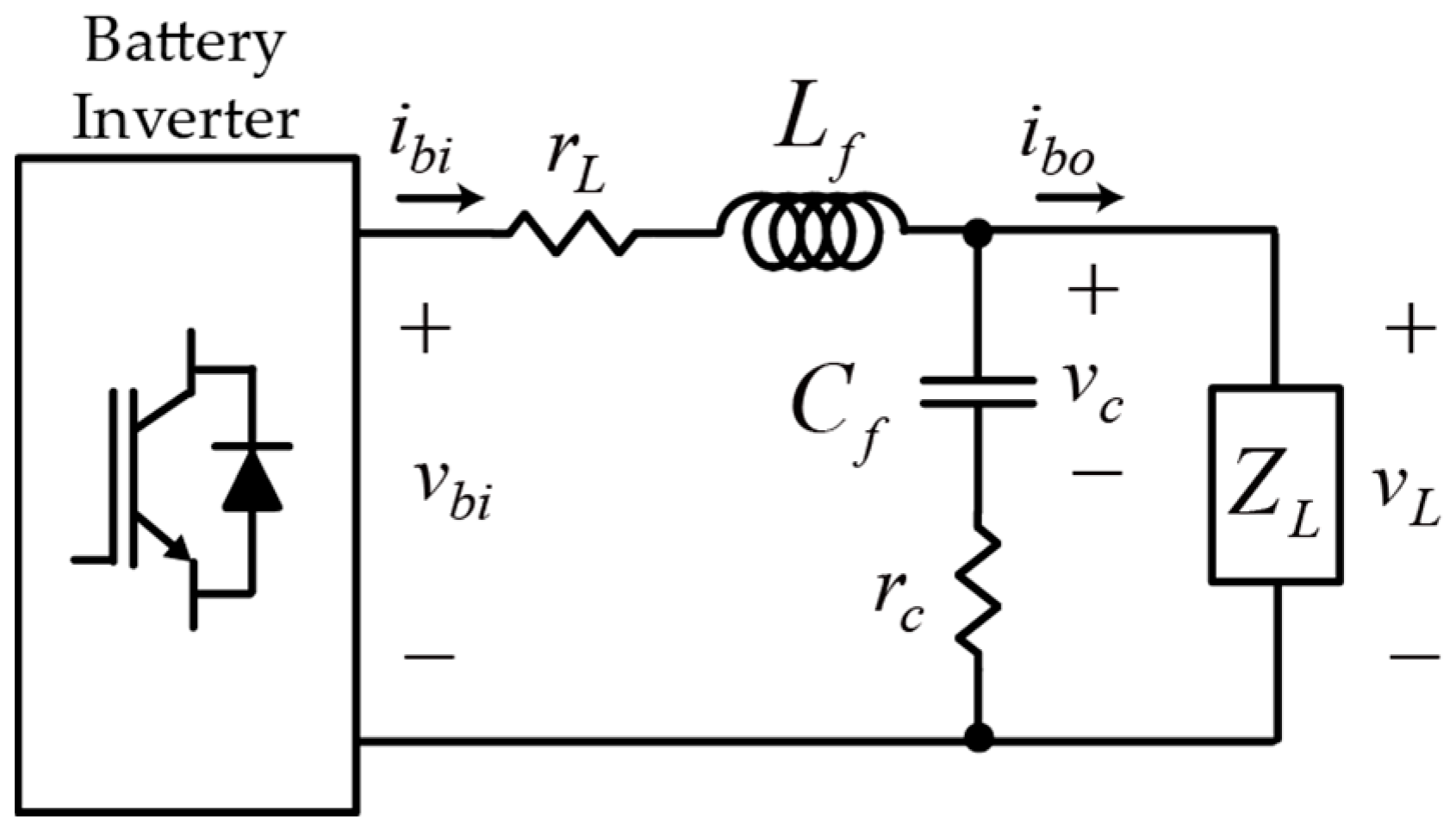
4.1. Voltage Control Model of the Grid-Forming Inverter
Figure 4 shows the voltage control model of the battery inverter in islanded mode of
Figure 3a. Here,
is the output filter inductor winding resistance, and
is the output filter capacitor equivalent series resistance (ESR).
and
normally have a small value below 0.5 Ω; therefore, they are often ignored during modeling. Nevertheless, they have a significant effect on the LC filter’s dynamic characteristics. In
Figure 4, the load current
is regarded as a disturbance, and the relationship between the inverter output voltage
and the load voltage
in a Laplace domain is:
where
is a Laplace operator. Because
and
are small values in Equation (1), which has the characteristics of a second-order low pass filter, the damping constant is usually much smaller than 0.707. Therefore, resonance is present in the LC filter output voltage.
When the second-order plant model of Equation (1) is directly controlled with the proportional-integral (PI) type controller, the resonance cannot be adequately removed to obtain complete sinusoidal voltage [
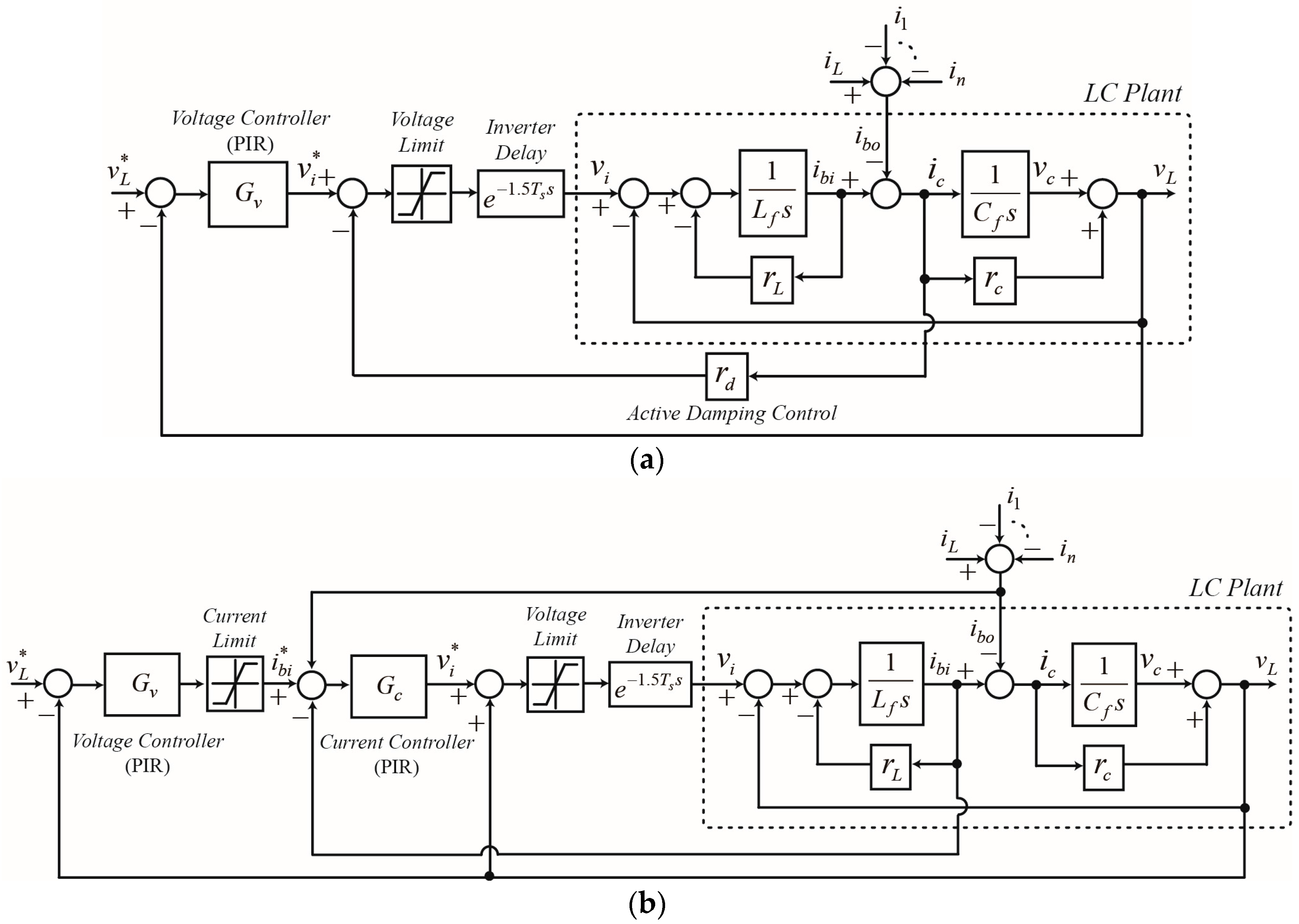
22]. Accordingly, the main methods for using an inverter to control the LC filter output voltage in a microgrid include adding a damping component to directly control the LC filter output voltage, or adding a current control loop within the voltage control loop.
Figure 5 depicts block diagrams of the two main voltage control methods for grid-forming inverters. It is evident that
is a disturbance input for the voltage control. As shown in
Figure 3a, this disturbance input
is the sum of the current consumed by the load connected to the local AC bus and the output current of the DG inverters in grid-following operation. According to the standard in [
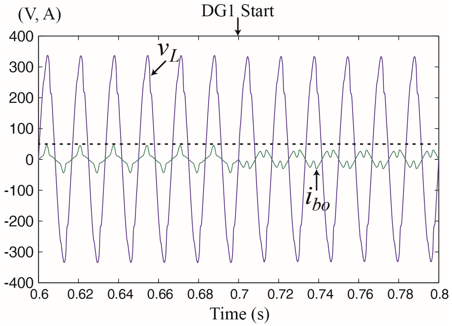
23], the output current of grid-following converters is always the 60-Hz sinusoidal current synchronized to the local AC bus voltage. Therefore, the grid-following DG inverters merely reduce the real power load on the local power network and do not affect the local microgrid’s power quality.
On the other hand, the load current, which is part of
, is a periodic wave that may include high-order harmonics. In grid-forming battery inverters, this high-order harmonic current can have effects such as changing the load impedance according to the time of one period. As a result, the voltage control characteristics significantly change for one period and cause high-order harmonic components in the output voltage. Therefore, the robustness against the load current disturbance is the most important performance indicator for voltage control in a grid-forming inverter that is part of a microgrid. Unpredictable current disturbance
is compensated with the proportional-integral-resonant (PIR) voltage control action in
Figure 5a, whereas it is measured and fed back into the voltage controller output in
Figure 5b. The PIR voltage controller
in
Figure 5a compensates not only the phase delay caused by the second-order resonant plant, but also the current disturbance
. On the other hand, the one in
Figure 5b compensates the phase delay caused by the inner current loop and capacitor dynamics.
4.2. Direct Voltage Control of the Grid-Forming Inverter
Figure 5a shows a resonant second-order system structure that directly controls the LC filter output voltage. The method of directly controlling the LC output voltage with a single controller, such as in
Figure 5a, is called direct voltage control (DVC). When PI-type controllers are used to directly control a resonant second-order system, the resonance cannot be damped by the controller. Moreover, the plant’s closed-loop poles are located on an imaginary axis; therefore, if the integral gain rises even by a minimal amount, the system immediately becomes unstable [
22]. Thus, before designing a PI-type control system, the resonance must first be damped.
To effectively achieve damping without additional energy loss, a software designed virtual resistance loop
rd is added in
Figure 5a. This method is known as active damping control, which is a necessary added control loop for using integral gain when controlling an LC filter with a PI controller [
22]. From
Figure 5a and Equation (1), the actively damped LC plant model becomes:
The damping term in the linear term of Equation (2) can be effectively changed by adjusting the virtual resistance
rd in the software. If a sensitivity function is found for the disturbance input
from the block diagram of
Figure 5a and Equation (2), it is:
Here,
Gv and
Ts are the voltage controller and the inverter’s pulse-width modulation (PWM) period, respectively. In this research,
Gv is the PI-type controller with a single phase system as the controlled plant. Thus,
Gv is made from a proportional-integral-resonant (PIR) controller, as follows:
Here,
,
, and
are the proportional gain, integral gain, and resonant gain, respectively.
4.3. Double Loop Control of the Grid-Forming Inverter
As shown in
Figure 5b, a two-line PI controller is used to control the LC filter output voltage [
17]. In this structure, an internal current controller is used to control the output inductor current, while an external voltage controller is used to control the final LC filter output voltage. This control structure has internal and external PI control loops connected in a series. It is therefore called double-loop control (DLC). Using the same method as previously described, the sensitivity function for the
ibo disturbance input of
Figure 5b is:
where
Gc is the PIR current controller as follows:
Here,
,
, and
are the PI current controller proportional gain, integral gain, and resonant gain, respectively. To compare their voltage control performances,
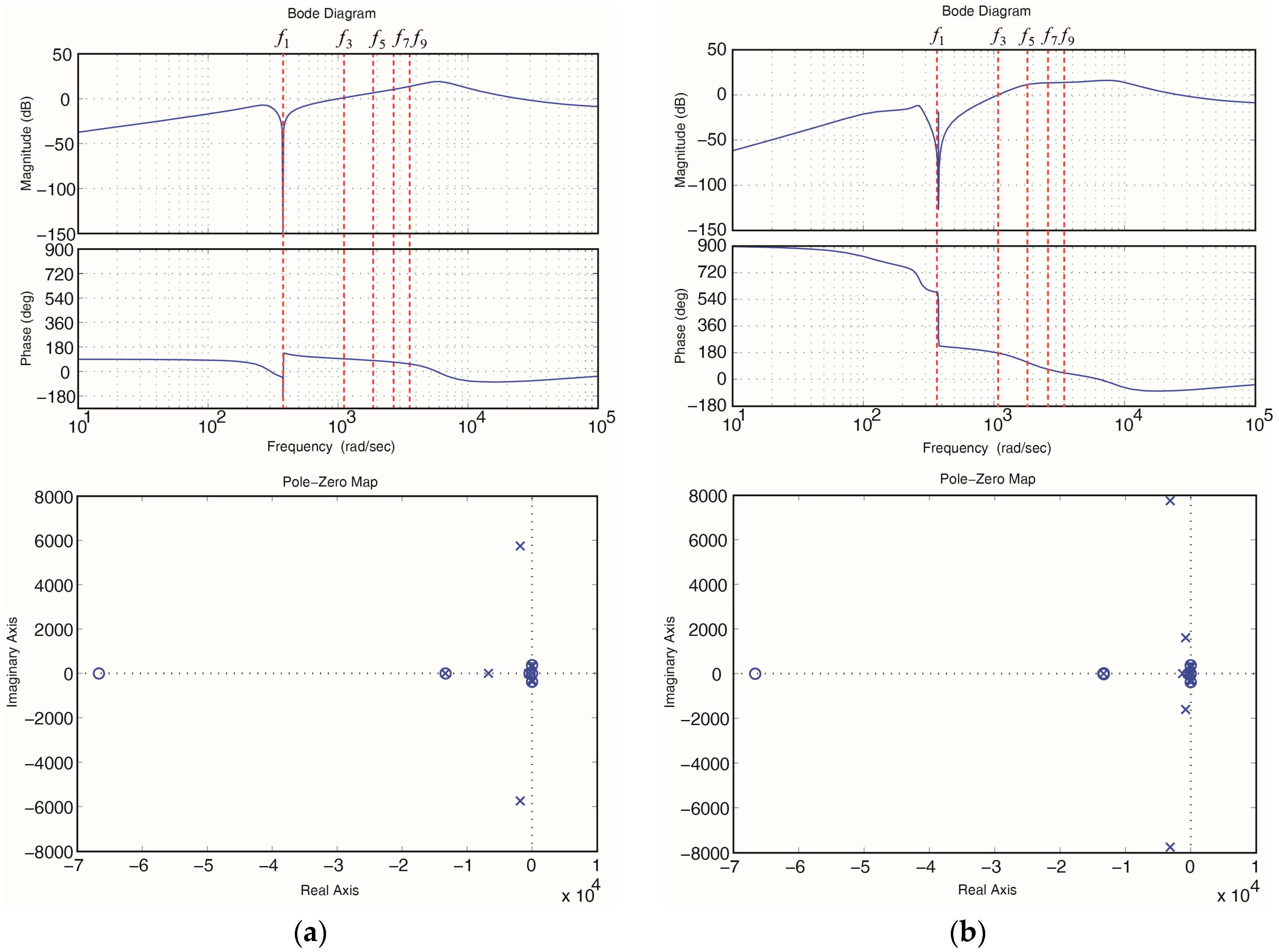
Figure 6 shows the frequency response of Equations (3) and (5). It is evident that DLC shows better attenuation characteristics for low frequency disturbance input in the magnitude response; at low frequencies, it shows a much greater phase shift than DVC. It is likewise apparent that DVC has better attenuation characteristics than DLC for the approximate fundamental frequency and disturbance input above 1100 rad/s. To more accurately analyze the high-order harmonic disturbance characteristics,
Table 2 shows the frequency response for the fundamental frequency (60 Hz) and the third, fifth, seventh, and ninth order harmonic disturbance components.
In
Table 2, the frequency response of
corresponding to the nominal frequency of the grid shows the sensitivity (robustness) of the output voltage to the real/reactive load current or the grid-following converter output current. Additionally, the third to ninth order harmonics show the voltage control sensitivity to nonlinear load current and the harmonic PWM noise. As shown in
Table 2, we can expect that DVC will show better attenuation characteristics than DLC for the grid-following inverter output current and the real/reactive load current disturbance. Furthermore, DVC operates more robustly for nonlinear load current and noise. In addition, as shown in
Figure 6, DVC is also better than DLC in terms of stability. However, we can expect that DLC, which has a low sensitivity, is much better for low frequency disturbances from low frequency oscillation that occurs on account of the line inductance and internal impendence of DGs in an inverter-based microgrid. Note that DLC shows better attenuation characteristics below
in
Figure 6b.
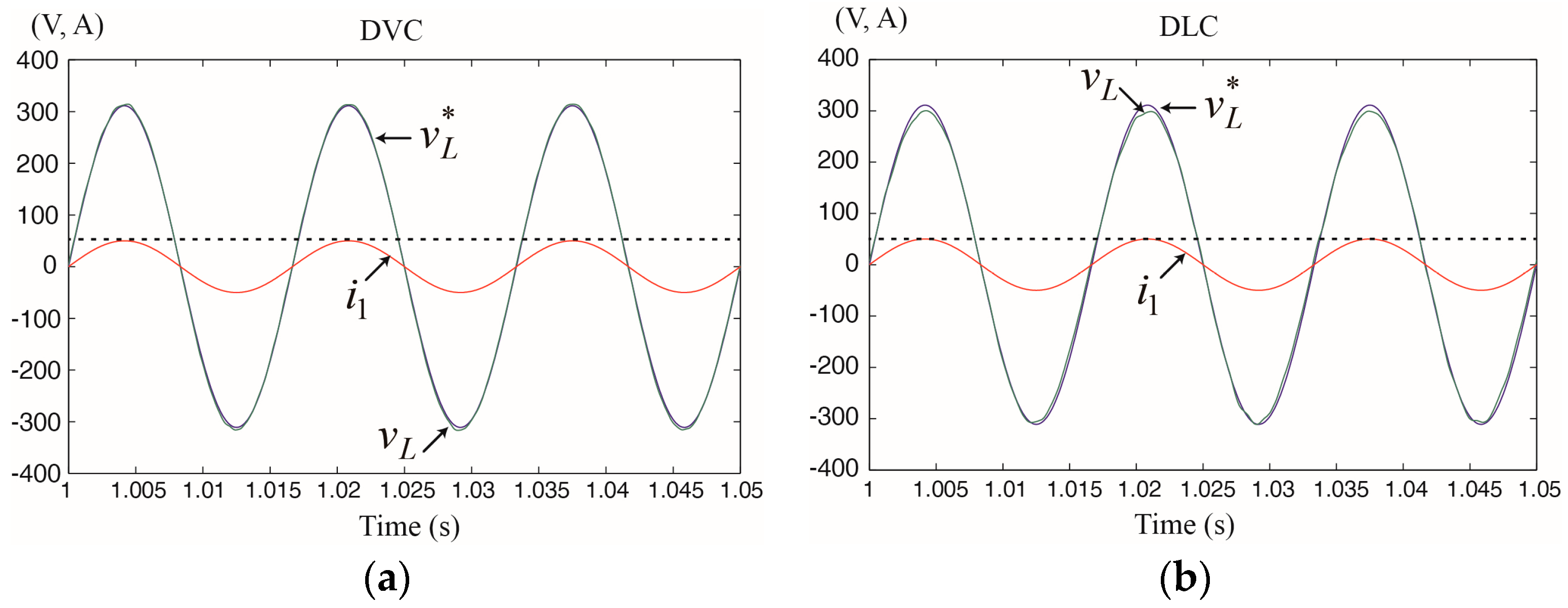
Based on the above results, when using DVC or DLC to create a microgrid’s grid-forming inverter, DVC has better dynamic properties for resistive, inductive, or nonlinear load currents that contain fundamental components and high-order harmonics. However, DLC has better dynamic properties for low frequency disturbances. In short, it is better to use DVC in circumstances that include many nonlinear loads, such as metropolitan or residential microgrids. Furthermore, it is better to use DLC in large non-metropolitan microgrids that have large line impedance due to relatively long distribution lines.
5. Battery Inverter Power Control in a Hybrid Microgrid
Assuming that local network AC voltage is well controlled by the battery inverter in an islanded microgrid:
and each grid-following DG is operated with power factor 1 [
23]. Thus, the
kth DG output current is:
where
Ik and ω
L are the
kth DG’s output current peak value and the angular frequency of the local AC bus voltage, respectively.
From the equivalent circuit in
Figure 3a:
The connection point voltage of each inverter’s connection point is
vL. Therefore, from Equations (7) and (9), the battery inverter’s output apparent power in islanded mode is:
The output active power that causes the battery charge and discharge is:
The battery inverter’s output reactive power is:
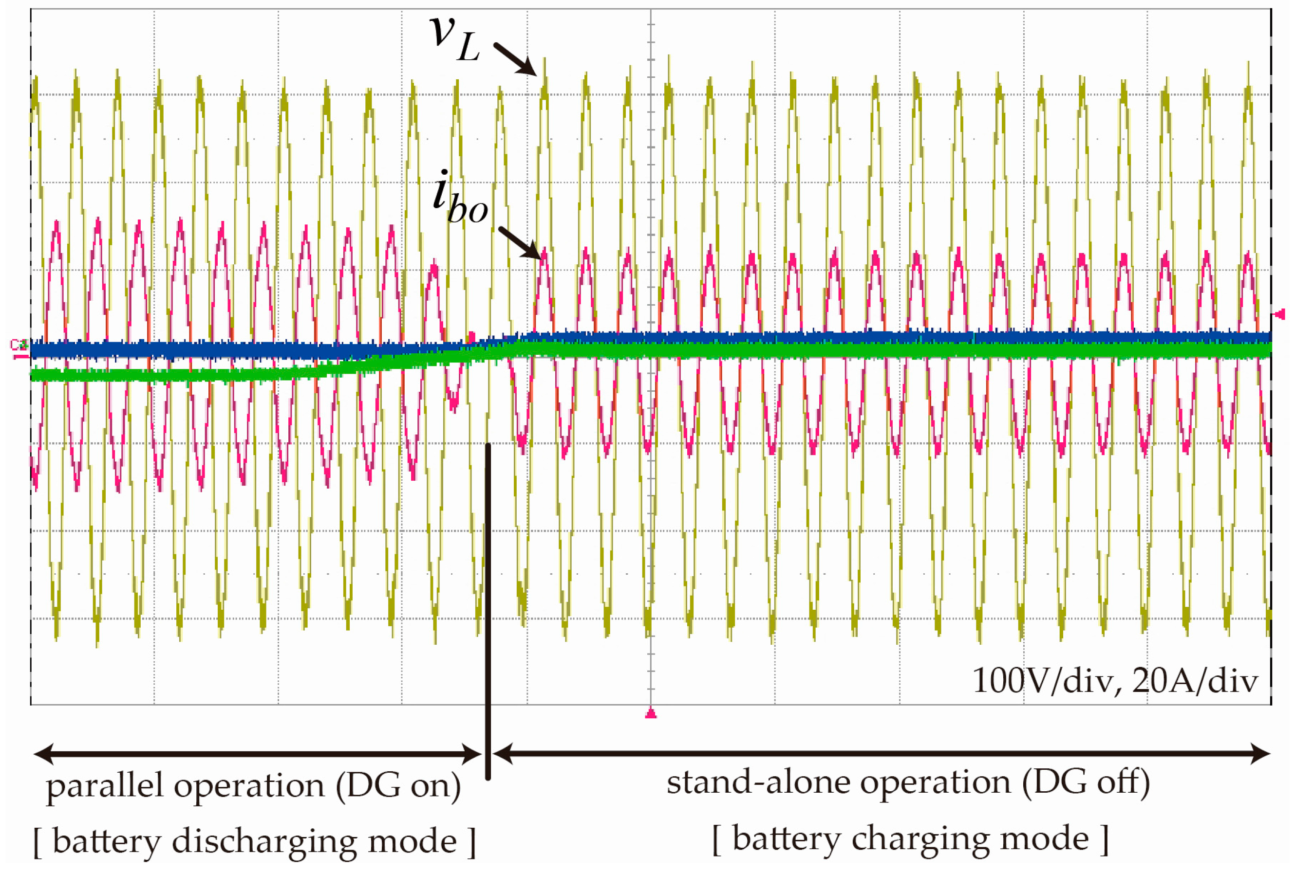
In a hybrid microgrid that combines grid-forming inverters and grid-following inverters, the battery inverter’s output active power is the sum of each DG’s output active power minus the active power load, as shown in Equation (12). This value is the power value that charges/discharges batteries in real time. Moreover, the reactive power load is completely controlled by the battery inverter. Assuming that the total harmonic distortion (THD) of the output current of all grid-following DGs is almost zero, Equation (10) becomes:
and the battery inverter equalizes the harmonic power of all local loads.
As a result, in a hybrid microgrid, the overall power quality of a local network is entirely determined by battery inverter performance. That is, the overall performance of the harmonic current and reactive power supply, which corresponds to the local network’s power quality, depends entirely on the voltage control performance of the battery inverter described above.
7. Conclusions
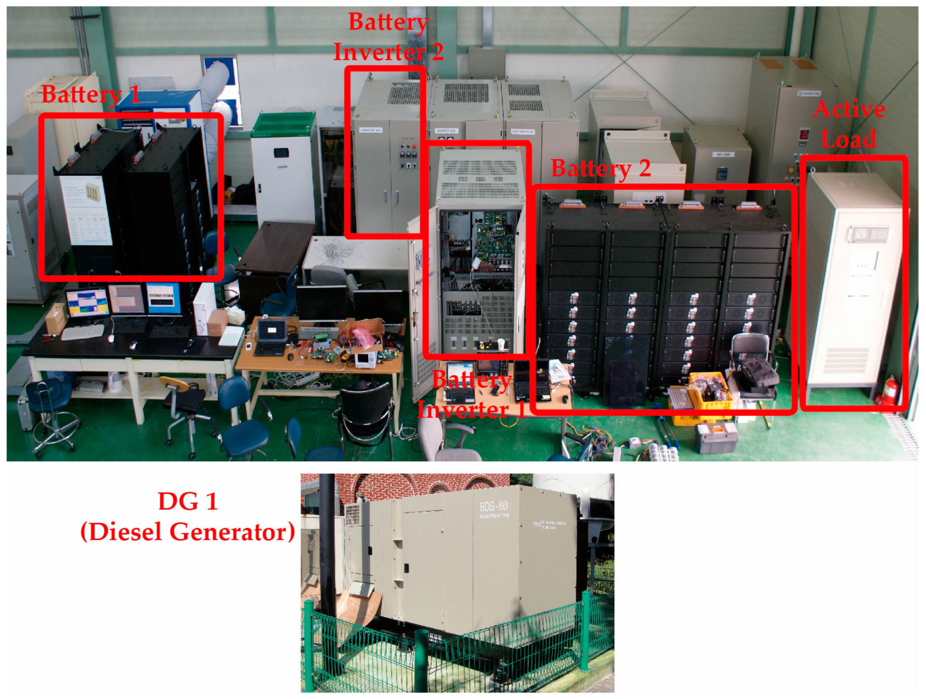
In this paper, we have analyzed and compared the performances of different grid-forming inverter voltage control methods in an inverter-based microgrid. The object of our study was a microgrid system in which the power converters used by batteries were comprised of grid-forming inverters; the remaining distributed generators were comprised of grid-following inverters. This microgrid structure is currently being commercialized by the Korea Electric Power Corporation (KEPCO) with a focus on island areas.
Control models were built according to the battery inverter control method. The models were used to perform frequency domain analysis. According to the frequency domain analysis, it is concluded that DVC is more stable and faster than DLC in terms of fundamental frequency and high-order harmonic disturbances, and DLC responds more robustly to low frequency disturbances. Therefore, DVC is considered suitable for metropolitan or residential microgrids in which there are nonlinear loads and a variety of connected distributed generators. On the other hand, DLC is better for non-metropolitan microgrids.
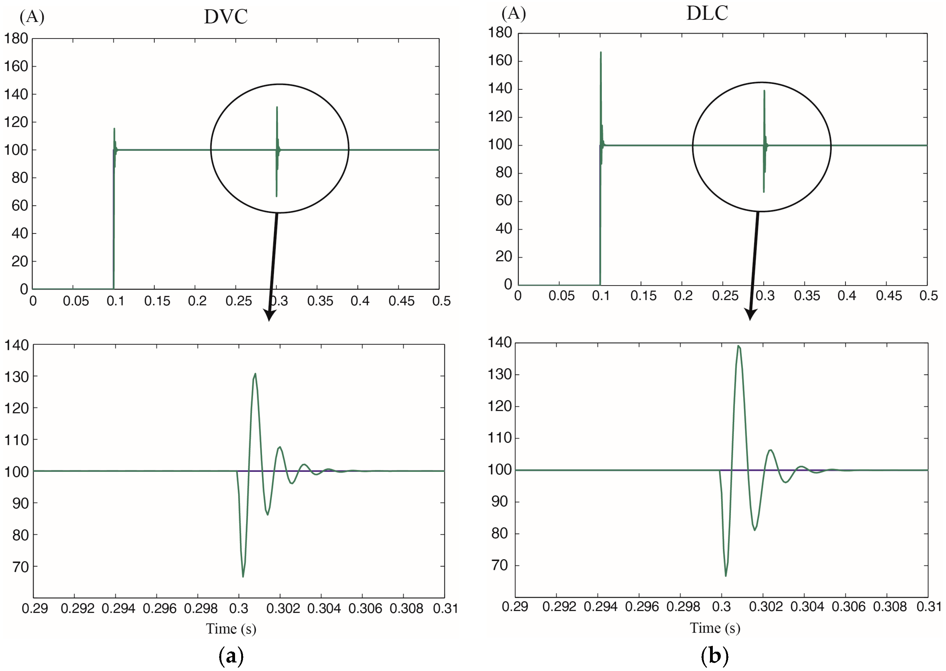
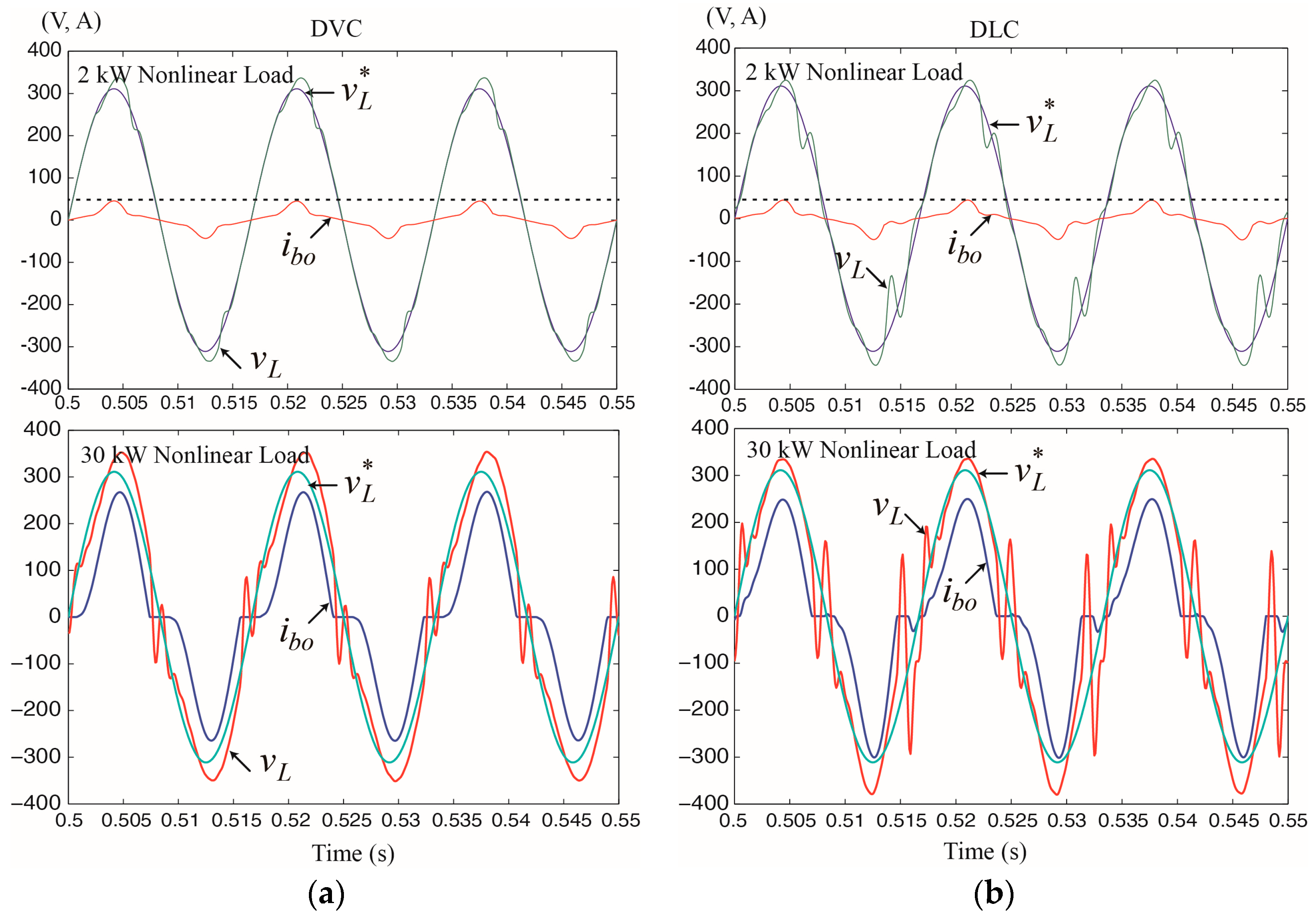
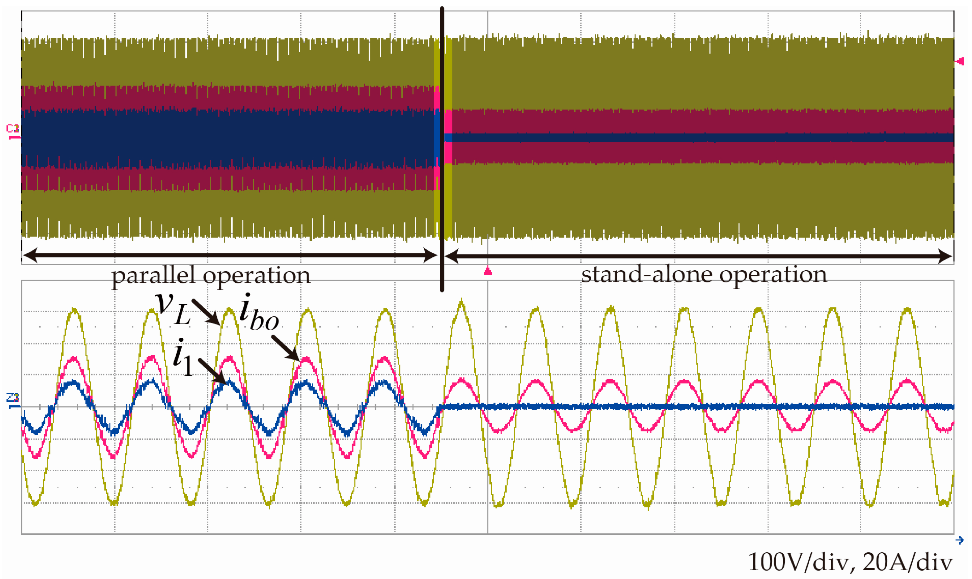
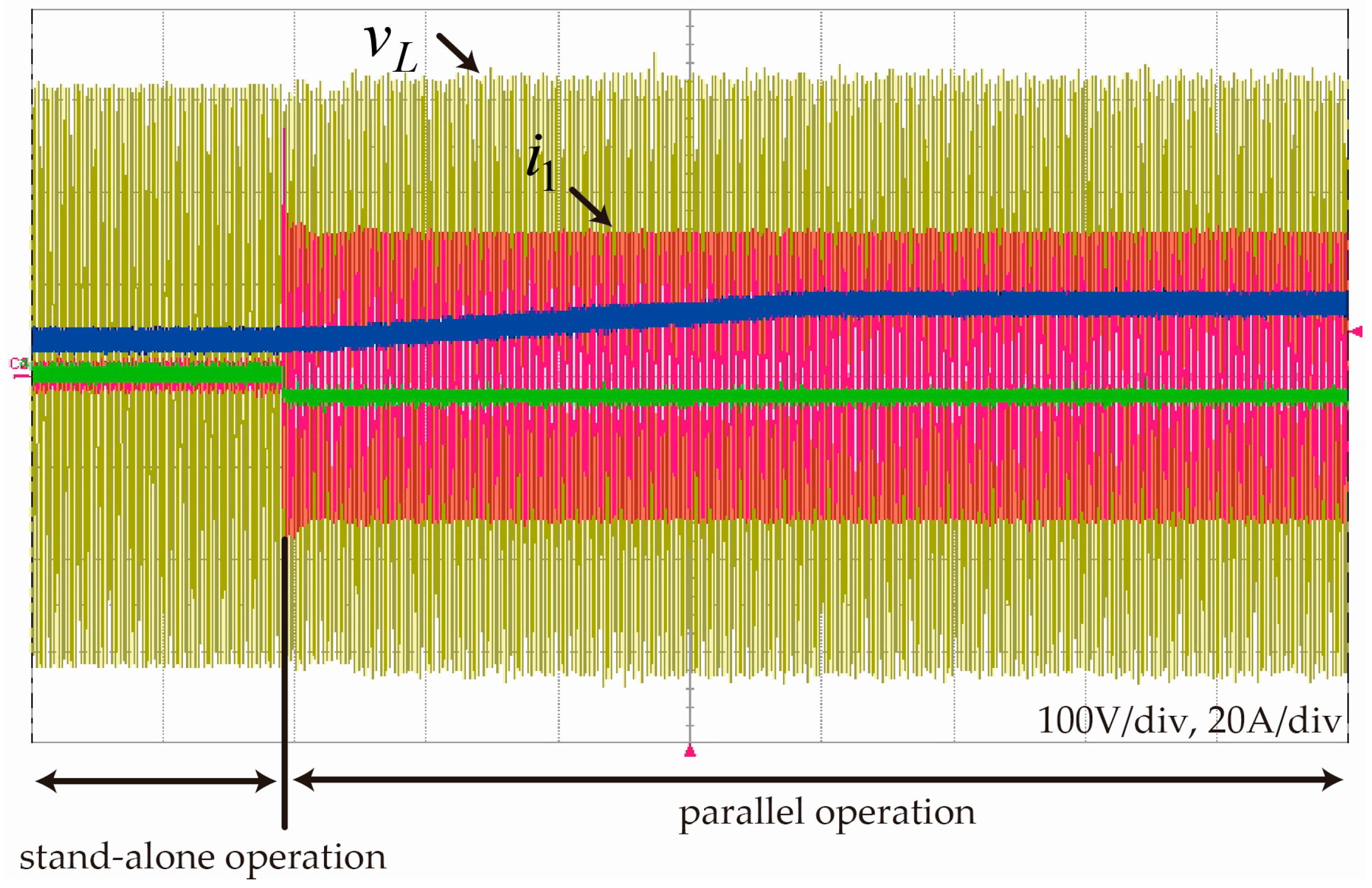
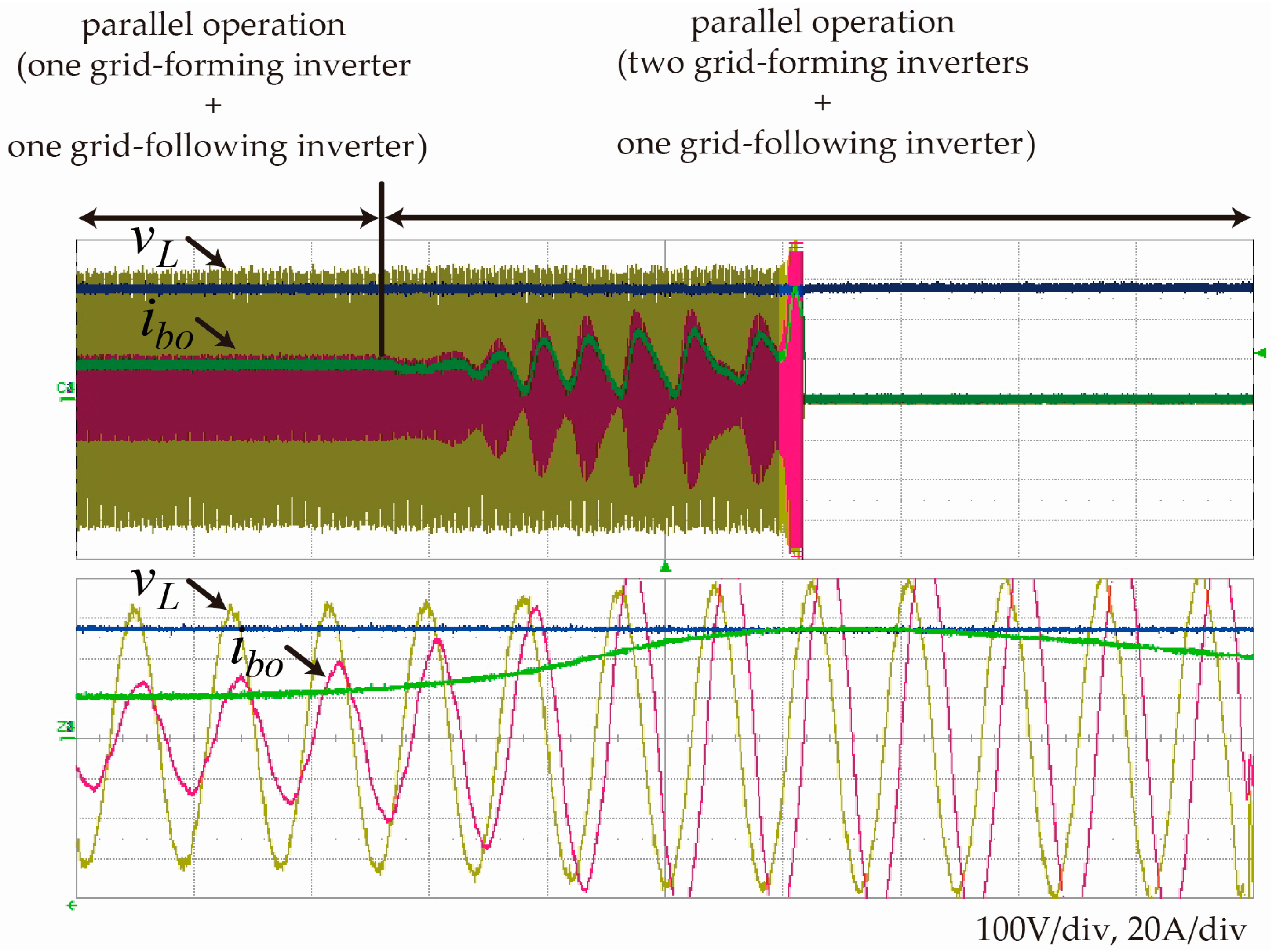
The analysis results were confirmed by simulations using physical models from the Matlab SimPowerSystems library and experimental results from a 50-kW testing platform. It is shown through the simulation results that the controlled voltage waveform with DVC is less vulnerable to the load current disturbance. It is also shown through the experimental results that DVC is more stable in abrupt load change conditions and the magnitude of low frequency oscillation is reduced with DLC. The purpose of this study was to analyze the control types in a hybrid microgrid composed of grid-forming and grid-following inverters. A PIR controller was adopted for single-phase AC voltage control. Further improvement can be made with a fast and stable control design, which will be developed in our next work.


