Article

Maximum Power Point Tracking Sensorless Control of an Axial-Flux Permanent Magnet Vernier Wind Power Generator

1
Department of Electrical Engineering, The Hong Kong Polytechnic University, Hong Kong, China
2
State Key Laboratory of Ocean Engineering, Shanghai Jiao Tong University, Shanghai 200240, China
*
Author to whom correspondence should be addressed.
Energies 2016, 9(8), 581; https://doi.org/10.3390/en9080581
Submission received: 23 March 2016 / Accepted: 15 July 2016 / Published: 26 July 2016

Abstract

:
Recently, Vernier permanent magnet (VPM) machines, one special case of magnetic flux-modulated (MFM) machines, benefiting from their compact, simple construction and low-speed/ high-torque characteristics, have been receiving increasing interest. In this paper, the Vernier structure is integrated with an axial-flux PM machine to obtain the magnetic gear effect and produce an improved torque density for direct-drive wind power generation application. Another advantage of the proposed machine is that the stator flux rotating speed can be relatively high when the shaft speed is low. With this benefit, sensorless control strategy can be easily implemented in a wide speed range. In this paper, an improved sliding mode observer (SMO) is proposed to estimate the rotor position and the speed of the proposed machine. With the estimated shaft speeds, the maximum power point tracking (MPPT) control strategy is applied to maximize the wind power extraction. The machine design and the sensorless MPPT control strategy are verified by finite element analysis and experimental verification.

Graphical Abstract

1. Introduction

Wind energy has been shown as one of the most feasible sources of renewable energy. Hitherto, the single-rotor wind power generation system is commonly used for its simple design, durability and less maintainability. The core element of this system is usually a gearbox based doubly-fed generator or a direct-drive synchronous generator. In this paper, a novel axial-flux permanent magnet machine (AFPMM) is presented for direct-drive wind power generation application.
AFPMMs have compact structures and short axial length, and these structure benefits make them suitable for assembling with the wind blades of wind turbine in wind power generation system. In this paper, a novel AFPMM with flux modulation and magnetic gear effect is presented. The Vernier structure is integrated with a dual-rotor axial-flux permanent magnet (PM) machine to obtain the flux modulation effect and produce an improved torque for direct-drive wind power generation application.
As the magnetic gear effect involved in the machine, the stator winding flux rotating frequency is high enough to use high-speed observer based sensorless control strategy when shaft speed is still low. This makes the sensorless control strategy more easily implemented. The use of sensorless control strategy can reduce the whole system cost as well as the failure rate of the system caused by sensor failures. Sensorless control of the permanent magnet synchronous machines (PMSMs) has become an active field of research in the last few decades. Among all the sensorless control strategies, sliding mode observer (SMO) is widely used due to its promising performance and excellent robustness to system structure. In this paper, the proposed machine’s stator winding flux rotating position and speed are estimated by using an improved SMO and the proposed SMO can run at the frequency of 6 Hz which has been verified by experiments. The real time speed estimation based maximum power point tracking (MPPT) control strategy is also proposed in the paper. To fit for the sensorless estimation strategy, a sluggish controller is introduced to smooth the torque output so as to improve the robustness of the SMO, and hence the MPPT tracking performance is enhanced accordingly.
In this paper, a prototype of axial flux permanent magnet Vernier machine (AFPM-VM) is built and its sensorless MPPT control experiments are carried out to verify the effectiveness of the control strategy.

2. AFPM-VM Design

Magnetic flux-modulated (MFM) machines attract increasing interests due to their magnetic gear effect and low-speed high-torque characteristics [1]. The idea of flux-modulated machines is initially derived from magnetic gears (MG) [2]. Through exploiting flux modulation segments in the airgap, the high-speed rotary magnetic field of MG caused by low number of PM pole pairs is modulated to asynchronous low-speed rotary fields. Hence, multi-pole rotor PMs interact with this high-order modulated magnetic field and are driven at a low speed to produce a constant torque. By replacing the rotary PMs with stationary balanced three-phase armature windings, the flux modulation effect can still be maintained and the gear effect is consequently integrated within electric machines [3]. Nevertheless, the concept of flux-modulated machines can be further generalized and extended. If the number of modulation segments is chosen to be a multiple of the stator tooth number, a Vernier PM machine is obtained, so Vernier PM machine is a special case of flux-modulated machines [4,5]. In this paper, a new AFPM-VM is proposed, in which the Vernier structure is integrated with an axial flux machine aiming to be used in a low-speed high-torque direct-drive wind power generation system.

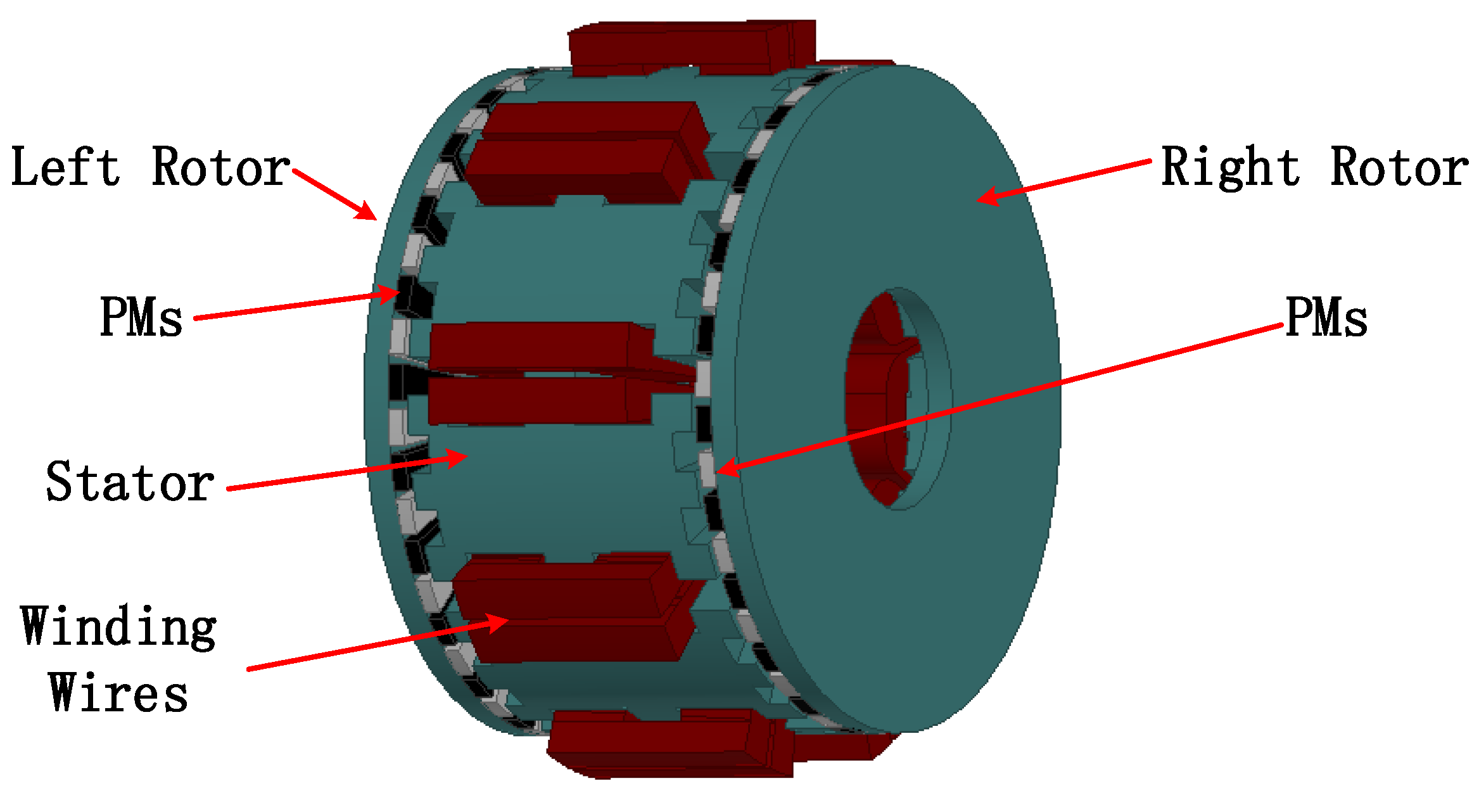
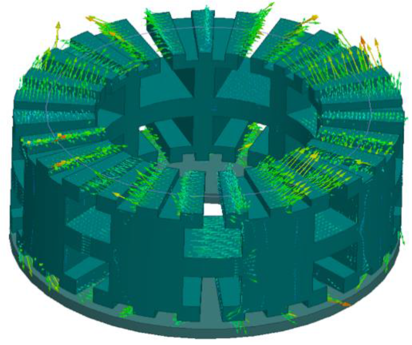
2.1. Machine Structure

Figure 1 shows the dual-rotor structure of the proposed AFPM-VM. The stator is sandwiched between the rotors. Both the left and right sides of the stator iron core have fake teeth to modulate the flux generated by the windings and rotor PMs and rotors have PMs surface mounted on them.
The combination of 8 poles/9 slots is chosen for the basic configuration and the stator tooth number is 27 and rotor PM pole pair number is 23. This slot and pole pair number combinations can effectively reduce the cogging torque. The wire diameter of stator winding is determined by the expected current density, and the number of turns and slot area are calculated by estimating the back-EMF from the input power and rated loading torque. Table 1 lists the specifications of the designed AFPM-VM.

2.2. Working Principle

As shown in Table 1, the stator and rotor pole pairs are not the same, which is the main difference between Vernier machine and traditional PMSMs. The pole pairs and speed relationships are discussed in this section.
Inspired by the concept of magnetic gear (MG), the flux-modulation poles are introduced as the stator fake teeth, which have the same function as the ferromagnetic segments of the stationary ring in the coaxial MG. Accordingly, the high-speed rotating magnetic field of the armature windings and the low-speed rotating magnetic field of the PM rotor are modulated [2].
Similar to the MG, the relationship between rotor PM pole pair number ( p r ), stator winding pole pair number ( p s ) and modulation pole number of the proposed machine ( N s ) is governed by
p r = N s p s
Consequently, the speed ratio G r is given by
G r = | m p s + k N s | m p s
where m = 1 , 3 , and k = 0 , ± 1 , ± 2 , . In the proposed machine, the combination of m = 1 and k = 1 is selected since it yields the highest asynchronous space harmonic [4]. There are 9 slots in the inner stator, which are occupied by three-phase 4 pole-pair armature windings. Each stator tooth is split into three flux-modulation poles, thus constituting totally 27 modulated poles, namely N s = 27 . From Equation (1), p r = 23 is resulted, which denotes that 46 PM poles are surface mounted on the rotor. From Equation (2), G r = 23 : 4 , which means that the rotor speed is only 4/23 of that in the conventional machine with the same armature winding pole pair number, but rotating in an opposite direction.

2.3. Analysis Method

The 3-D time-stepping finite element method (FEM) is used to analyze the performance of the proposed AFPM-VM. The plot of the magnetic flux density on the surface of one side of the stator is shown in Figure 2. It shows that at the air gap, the magnetic flux produced by the stator windings has been modulated to 23 pole-pairs. The back Electromotive Force (back-EMF) analysis results are shown in the Figure 3. It shows the no-load back EMF waveforms at the speed of 400 rpm and calculated peak values of the back-EMF from 50 rpm to 400 rpm.

2.4. Advantages of the Proposed AFPM-VM

Compared with the conventional AFPM machine designs, the proposed machine enjoys the following advantages:
(1)
By introducing Vernier structure into the AFPM machine, the magnetic gear effect works in the designed generator. The electrical frequency is multiples of the shaft rotating frequency, which is very suitable for low-speed direct-drive wind power generation.
(2)
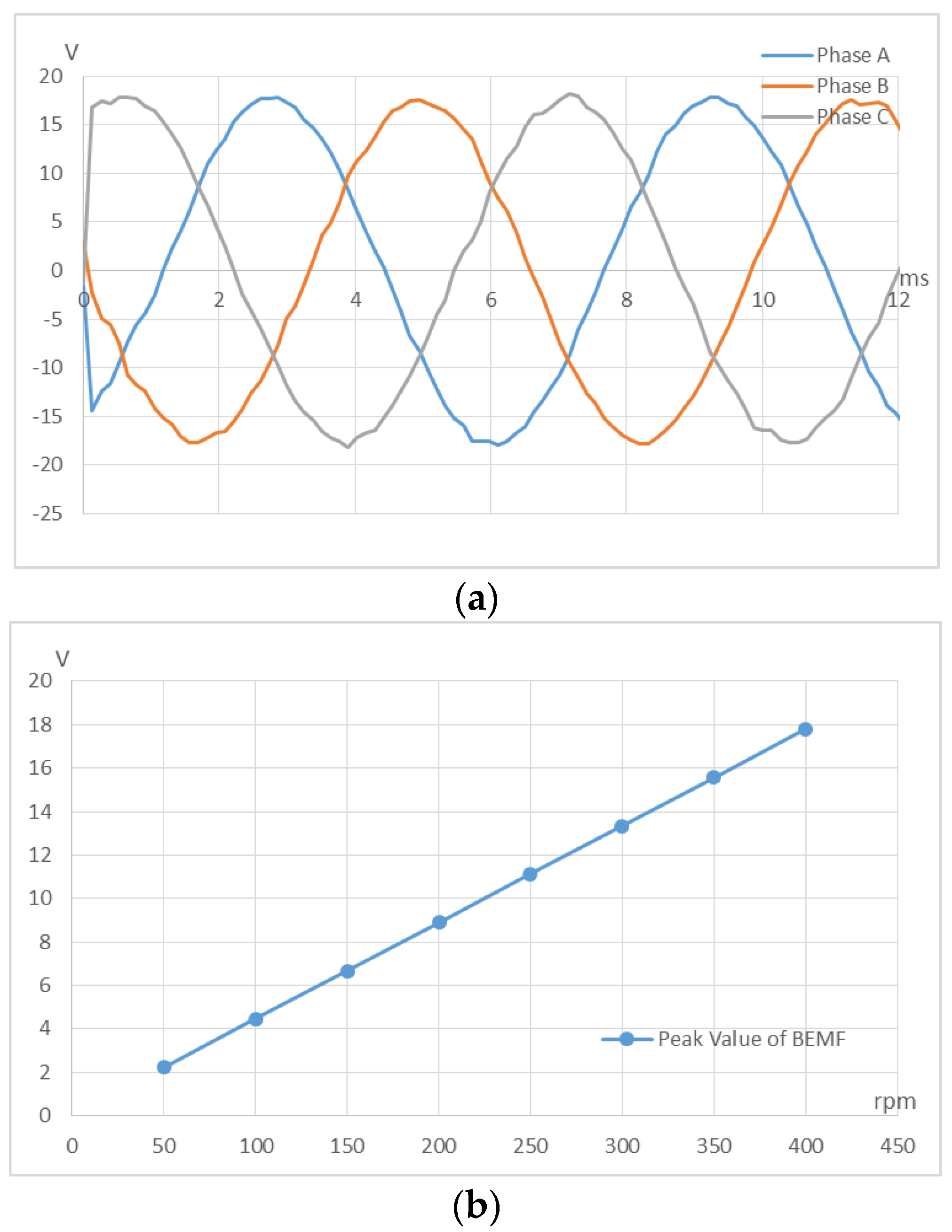
The proposed generator can produce high-frequency stator windings currents when shaft speed is low, and thus high speed sensorless control strategy can be easily implemented.
(3)
The Vernier machine design inherently provides a convenient design method to accommodate a large number of PM poles in rotor, and small number of slots and winding pole pairs in stator. This design enables a high filling factor of the inner stator space to accommodate the armature windings and very suitable for low-speed high-torque direct-drive operation;
(4)
The dual rotors allow for direct coupling with the wind turbine, thus alleviating the bearing requirements and improving the mechanical integrity;
(5)
Dual PMs can interaction with both sides of the stator windings, which can improve the torque density. Concentrated winding connection in the stator results in a compact structure to improve the torque density accordingly;
(6)
The concentrated winding connection reduces the end-windings, and makes the assembling convenient.

3. Sensorless MPPT Control of AFPM-VM

Sensorless control of the PMSMs has become an active field of research in the last few decades. The works in [6,7,8,9,10] present some sensorless control strategies for PMSMs, which include extended Kalman filters (EKFs), model reference adaptive system (MRAS), model predictive control (MPC), and observer-based control such as Luenberger observer (LO), sliding mode observer (SMO). Among these control theories, SMO is widely used due to its promising performance and excellent robustness to system structure [11,12,13].
The SMO based sensorless control strategy is used in the proposed AFPM-VM. The high-speed sensorless control strategy for the machine is mainly discussed in the paper as low speed area is not the main working area of wind power generation system. In this paper, an improved SMO with phase locking loop (PLL) is proposed for the AFPM-VM position and speed estimation.

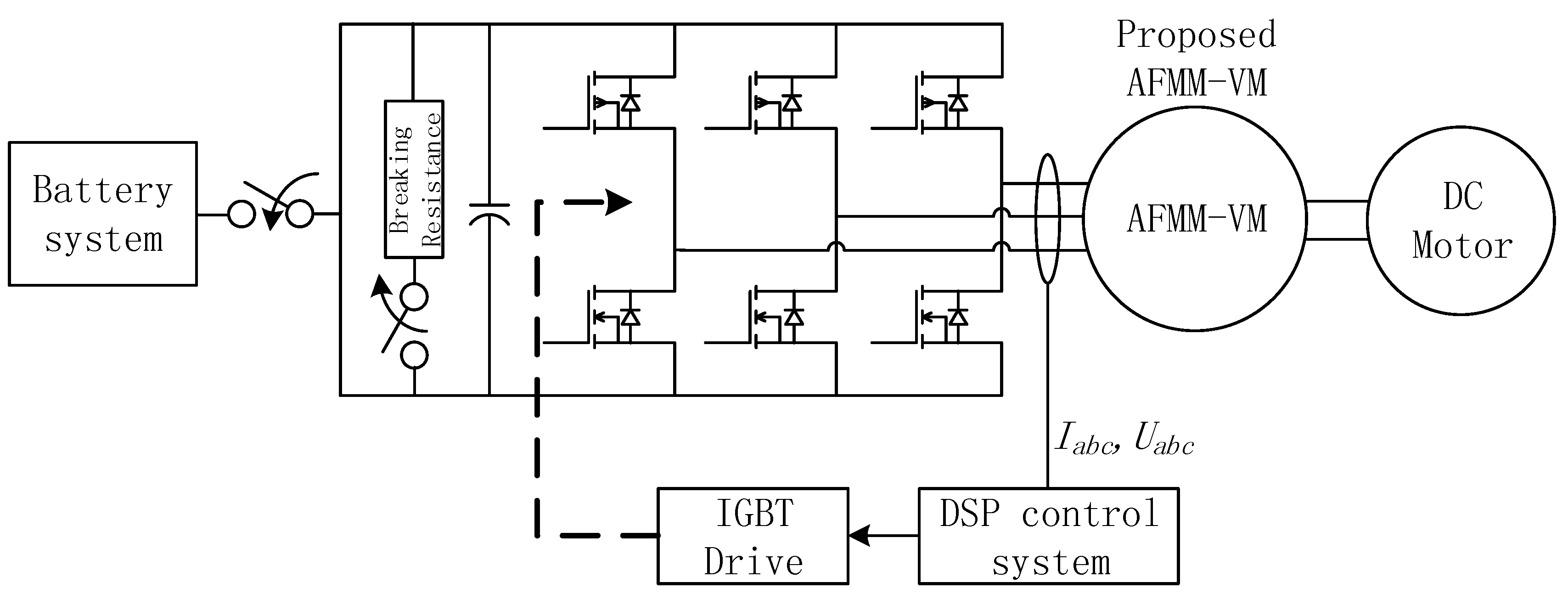
3.1. Hardware Setup and Working Principle for Low Rotor Speed

The proposed AFMM-VM is used for battery charge in the experiment testbed, and a DC motor is used to simulate the wind turbine. The system hardware setup is shown in the Figure 4, and a 3-phase inverter is used for the MPPT control of the generation system, and the phase current and voltage are measured for the position and speed estimation.
As discussed in Section 2.1 and Section 2.2, the machine’s rotor has 46 poles and the stator has 8 poles, the stator flux rotating frequency is 23/4 multiples that of the rotor, and in opposite direction. If the rotor runs at 15 rpm, which is the 3.75% of the rated speed, the stator flux frequency will goes to 6 Hz. With such frequency and above, the SMO position estimation system can work properly.
When the rotor speed is too low for the SMO estimation, it also can be considered as the wind speed is too low for the wind generation. The generation system shuts down all the switching elements and DC capacitor is charged by the uncontrolled rectifier. The power expands with the breaking resistance, and the current is measured for the speed estimation. When speed is high enough, the system bypasses the breaking resistance and starts to control the switching elements to charge the battery system.

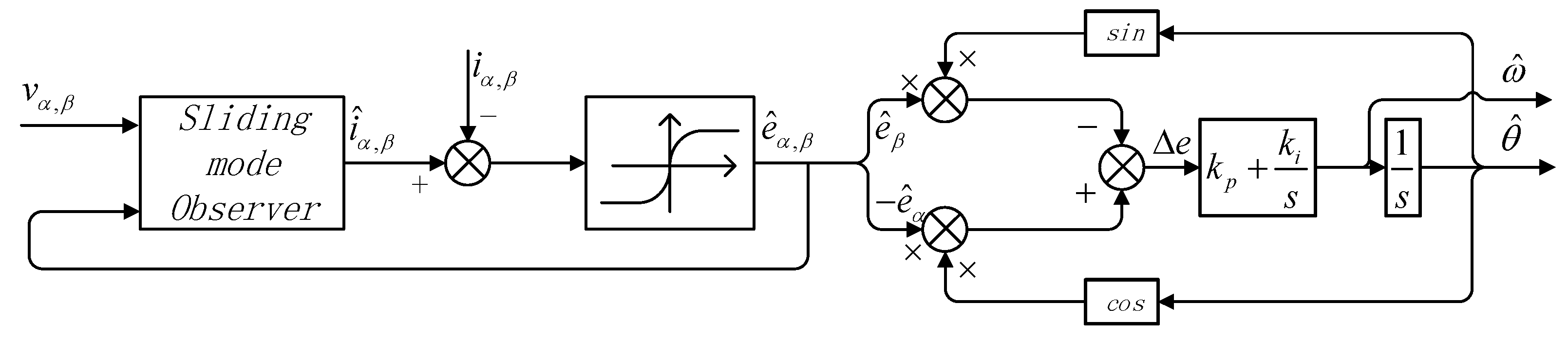
3.2. Position and Velocity Estimation

When speed is high enough, SMO can be used for the position and velocity estimation based on the phase current and voltage. The model of the proposed machine, in the stationary reference frame, is described by the following Equations:
[ d i α d t d i β d t ] = [ R L 0 0 R L ] [ i α i β ] + [ 1 L 0 0 1 L ] [ v α v β ] + [ 1 L 0 0 1 L ] [ e α e β ]
where i α , β , e α , β and v α , β represent the current, back EMF, and supply voltage of each phase, respectively. R and L represent the stator resistance and inductance, respectively.
The back-EMF for each phase can be represented in the fixed frame as
[ e α e β ] = [ λ f ω s 0 0 λ f ω s ] [ sin θ cos θ ]
in which λ f , ω s and θ represent the modulated magnetic flux of the PM dual rotor, the stator electrical angular velocity, and rotor angle, respectively. The velocity of the rotor, as discussed in the Section 2.2, can be represented as
ω r = ω s / G r
As shown in Equation (3), the voltages v α , β and currents i α , β are the known quantities. The objective is to design an observer to estimate the back-EMF e α , β using the available measurements. SMO is fit for the estimation due to its robustness against system parameter variations. The sliding mode control changes the system states to ensure that those on the sliding surface are robust against parameter variations and disturbances.
The SMO is composed by the current equation as the same form of Equation (1) as follows:
[ d i ^ α d t d i ^ β d t ] = [ R L 0 0 R L ] [ i ^ α i ^ β ] + [ 1 L 0 0 1 L ] [ v α v β ] + [ 1 L 0 0 1 L ] [ k S g n ( i ˜ α ) k S g n ( i ˜ β ) ]
in which, S g n ( i ˜ s ) is the signum function in conventional SMO with i ˜ s = i ^ s i s (subscript s represents α and β ). The result of the signum function is either 1 or −1, so it may cause chattering problem. To eliminate the undesirable chattering, a saturation function is adopted in this research as the switching function. In the paper, a sigmoid saturation function Z ( i ˜ s ) is used to replace the signum function S g n ( i ˜ s ) in conventional SMO. The proposed saturation function has two switching surfaces ( i ˜ s = δ , i ˜ s = δ ), it is a linear function in the boundary, and a continuous function in the sliding surface. The saturation function is represented as
Z s ( i ˜ s ) = { sgn ( i ˜ s ) , sin ( π i ˜ s / 2 δ ) , | i ˜ s | > δ | i ˜ s | δ
where δ represents the switching surfaces threshold.
The proposed SMO is shown as follows:
[ d i ^ α d t d i ^ β d t ] = [ R L 0 0 R L ] [ i ^ α i ^ β ] + [ 1 L 0 0 1 L ] [ v α v β ] + [ 1 L 0 0 1 L ] [ k Z ( i ˜ α ) k Z ( i ˜ β ) ]
Comparing the Equations (3) and (8), the back EMF can be estimated by the Equation
e ^ s = k Z ( i ˜ s )
where s represents α and β . The estimated back-EMFs, which are the results of the SMO, can also be represented as:
{ e ^ α = λ f ω s sin θ e s t e ^ β = λ f ω s cos θ e s t
in which θ e s t is the estimated stator flux position according to the SMO result. The stator flux position is related to the rotor position, as shown in Equation (5).
The undesired fluctuation and noises of the estimated back-EMF may directly affect the rotor position and speed estimation. Especially, when θ e s t is close to 0 or π / 2 , the e ^ α and e ^ β will vary considerably, and one of them is close to 0, which may make the calculation of the θ e s t inaccurate. To overcome this problem and further suppress the chattering problem, A PLL for the estimated back EMF is proposed. Figure 5 shows the proposed improved SMO flow chart in which a Z ( i ˜ s ) function is used as the switching function and PLL is used to suppress the chatting activity from the switching.
As shown in Figure 5, the position estimation error, which marked as Δ e in the figure, can be derived as:
Δ e = e ^ α sin θ ^ e ^ β cos θ ^ = λ f ω s cos θ e s t sin θ ^ + λ f ω s sin θ e s t cos θ ^ = λ f ω s sin ( θ e s t θ ^ ) λ f ω s ( θ e s t θ ^ )
θ ^ as the final result of the SMO, which is marked in Figure 5, is equal to the θ e s t when Δ e = 0 . The convergence of the PLL close loop and its PI controller can be proved using its transfer function, θ e s t is the input of the PLL and θ ^ is the output, the close loop transfer function and error function of the PLL system can be derived as:
{ G ( s ) = k e k p s + k e k i s 2 + k e k p s + k e k i G e ( s ) = s 2 s 2 + k e k p s + k e k i
in which k e = λ f ω ^ r .
The speed can be treated as a constant in one PLL calculation loop, the steady state error of the PLL system is:
Δ e ( ) = lim s 0 s Δ e ( s ) = lim s 0 s s 2 + k e k p s + k e k i = 0
The system is convergence, and then the rotor position and velocity are detected from the estimated back EMFs.

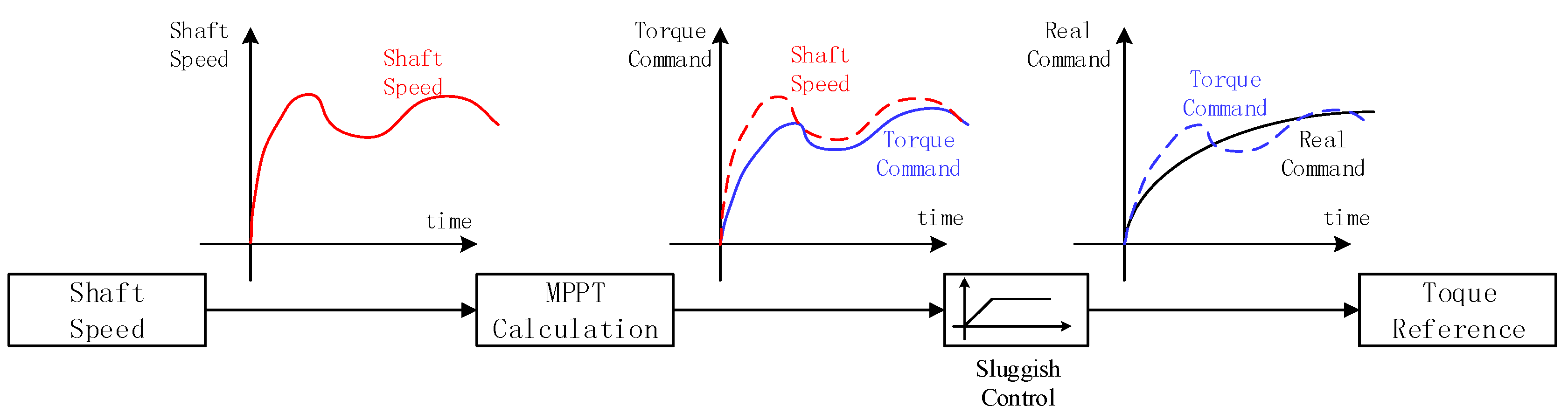
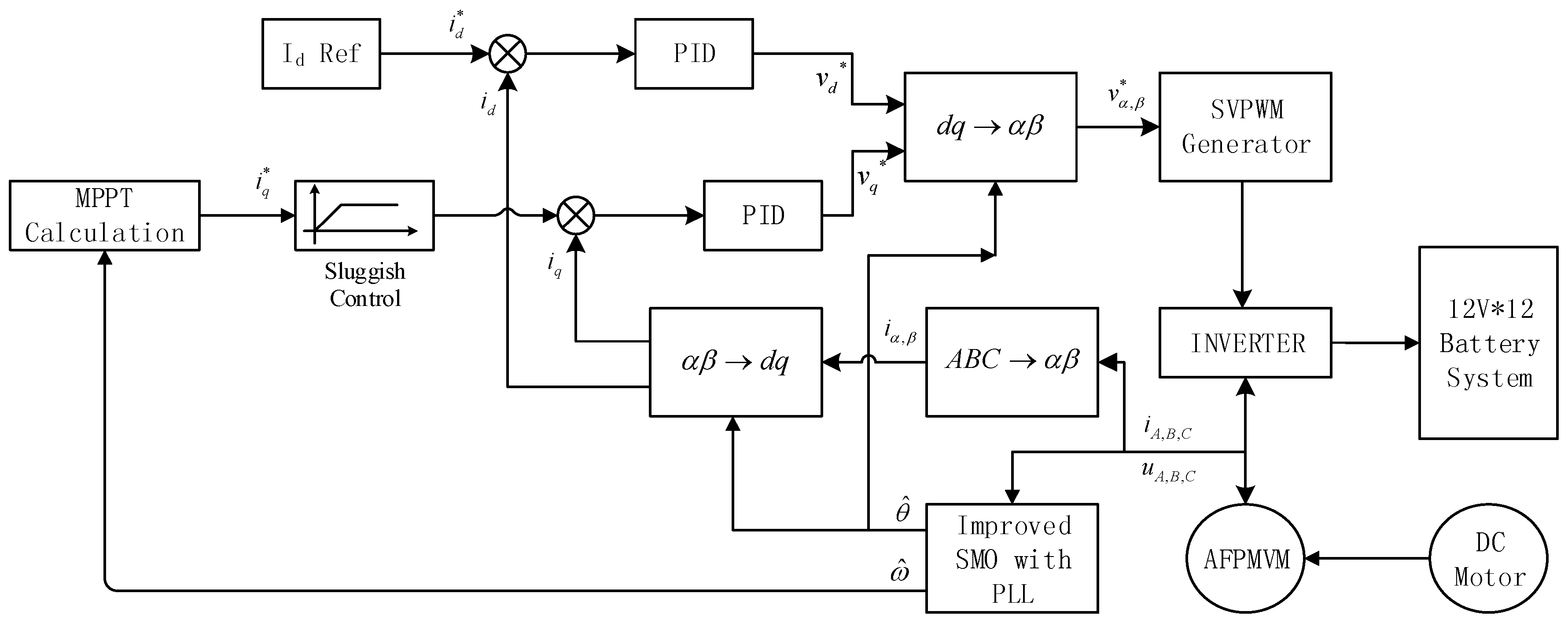
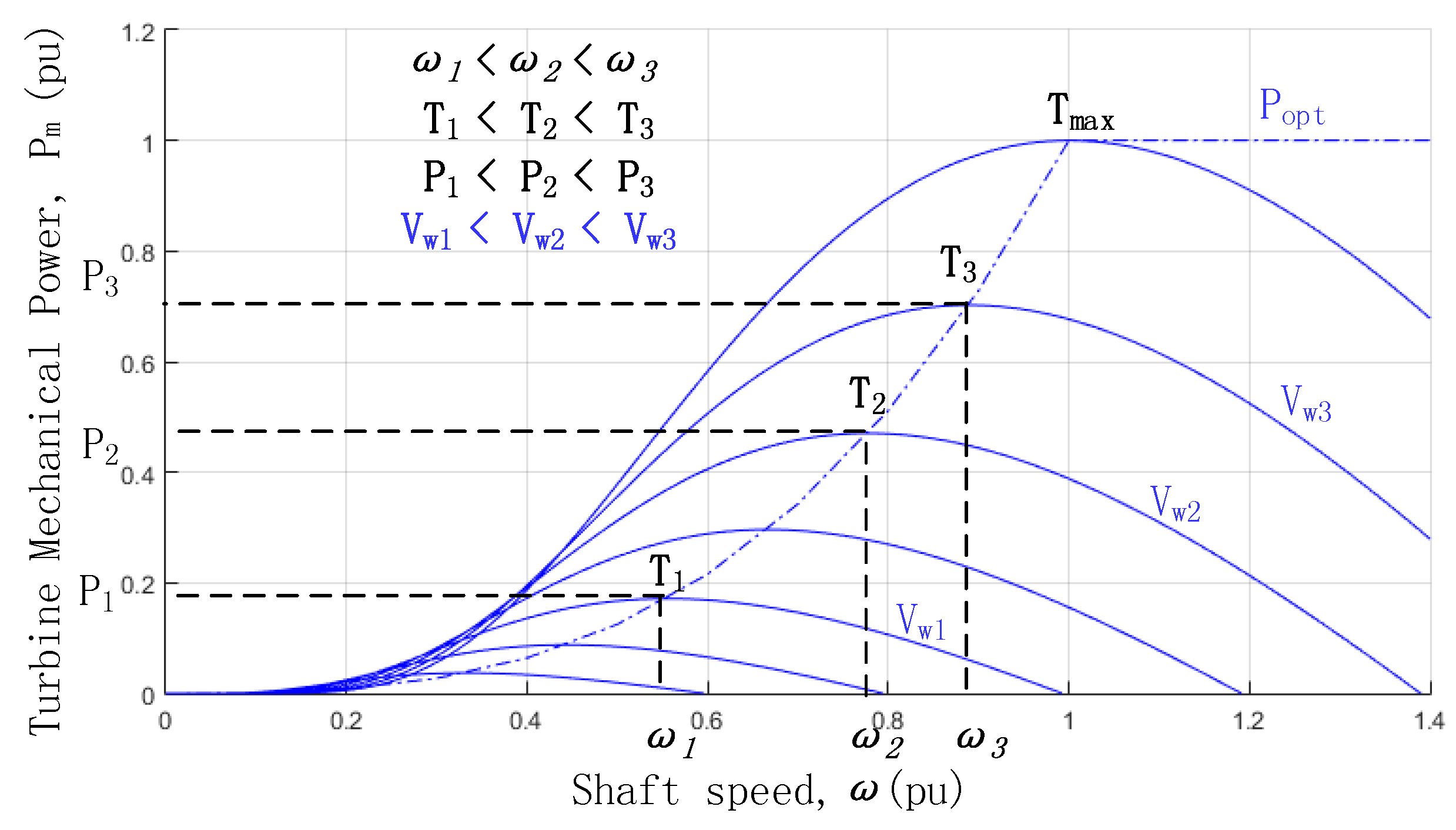
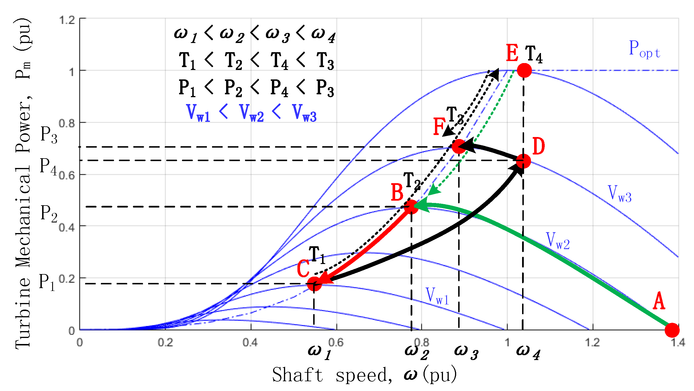
3.3. Sensorless MPPT Control of AFPM-VM

MPPT control strategy, whose aim is to maximum use the wind power, can be used in the proposed machine with estimated shaft speed. The power captured by the blades of wind turbines can be described as the Equation:
P m = 0.5 C p ρ S v 3
in which C p is the wind turbine power coefficient, ρ is the air density, S is the blade area and v is the wind speed. The parameter S is constant if the wind turbine has been decided, and ρ is obviously constant. That means when wind speed keeps constant, the output power of the wind turbine is only related to its power coefficient C p . C p is related to tip speed λ , which can be described as C p = f ( λ ) . λ can be described as λ = ω r b l a d e v . ω is the rotating speed of the wind turbine as well as the generation shaft, and rblade is the radius of the wind turbine.
Accordingly, the rotating speed and output power of the wind turbine under different wind speeds are shown in the Figure 6. The power curve monotonously changes in both sides of its maximum power point. In the Figure 6, the target of the MPPT control strategy is to let the system runs at the maximal power point Popt at every wind speeds. In conventional MPPT control strategy, wind speeds can be measured by the anemometers, and thus the generation rotating speed can be decided accordingly. However, it is hard to measure the actual wind speed on the blade by anemometers. To overcome the problem, in this paper, a sensorless MPPT control strategy is proposed according to the shaft speed of the AFPM-VM, which is estimated with improved SMO as mentioned in Section 3.2.
According to the Popt curve, a series of the torque and speed value are stored in the AFPM-VM control system, and each shaft speed has a shaft torque value correspondingly. As shown in Figure 6, with the wind speed Vw1, the rotating speed ω 1 corresponds to the maximum power, and the torque of this point T1 is stored accordingly. The torque at the maximum power points under different wind speeds, namely T2 and T3, are also stored, similarly. Thus, a curve of shaft speed and torque is made, and we name it Popt/Topt curve, which is the control target of the wind power generation system. The system aims to control the torque on the shaft according to this curve, and the system runs to reach the maximum power points under different wind speeds. An example of the control strategy is shown in Figure 7.
As shown in Figure 7, Popt/Topt curve is the basis of the AF-VMPM MPPT control. Taking point A as the starting point, under wind speed of Vw2, the generation system combines to the power grid, and shaft torque and output power are 0, and MPPT starts. From point A to B, the generation system sends power to the grid, so the shaft torque increases and rotating speed decreases. The shaft torque gradually goes up to catch the torque target at each speed. The torque target, marked as green dotted line in the figure, gradually goes down when rotating speed goes down. The system goes from point A to point B along the green line in the figure. At point B, the shaft torque reaches the target eventually and the generation system reaches the max power output point. At this time, the shaft speed is ω 2 and torque is T2.
When wind speed goes down from Vw2 to Vw1, the torque provided by the wind turbine is lower than the shaft torque generated by the generation system, the system cannot maintain stable in point B and the shaft speed will decrease. The torque target continuously goes down as speed goes down. At ideal conditions, the torque can strictly follow the torque target changes, the system will run from point B to C along the red line in the figure. This means the system runs by the Popt/Topt curve. At point C, the system researches the max power point at the wind speed of Vw1.
It is a common sense that the rapid changing of the torque will have bad effects to the position estimation. To avoid this problem in the MPPT, a sluggish control module is used to smooth the torque change ratio. The torque command generated by the MPPT Calculation module is smoothed by the sluggish control unit, as shown in Figure 8.
If the sluggish control unit is applied between the MPPT and the real shaft torque, in other words, shaft torque changes more slowly than the target changes, the system will not run by the Popt/Topt curve but can still get to the max power point. The situation is shown as point C to F in Figure 7. When wind speed goes up from Vw1 to Vw3, the shaft speed goes up and torque target goes up accordingly. As the torque provided by wind turbine is higher than the torque generated by system, the system goes to D point along the solid black curve in the figure. At point D, the shaft speed is ω 4 which is higher than ω 3 , and the shaft torque is greater than T1 but smaller than T3. The torque target is T4 as marked in point E, which is greater than T3. At D point, as the shaft torque is not equal to the target, the system is still not stable and the control strategy continues to work. The shaft speed goes down as shaft torque continues to go up. Meanwhile, the torque target goes down accordingly, following the black dotted line from point E to F in the figure. The system reaches steady stable at the point F, at this point, the shaft torque and target are equal to T3 with the shaft speed of ω 3 .
With the discussion for the Figure 7, conclusion can be drawn that if the shaft torque follows the torque target defined by Popt/Topt curve according to the shaft speed, the system will always reach its max power points at every wind speeds. As the shaft speed can be estimated by the AFPM-VM current and voltage, the sensorless MPPT control strategy can work properly in the system.

4. Experiment Results

To verify the machine design, a prototype AFPM-VM is produced and experiments of the sensorless MPPT control is carried out in this paper.

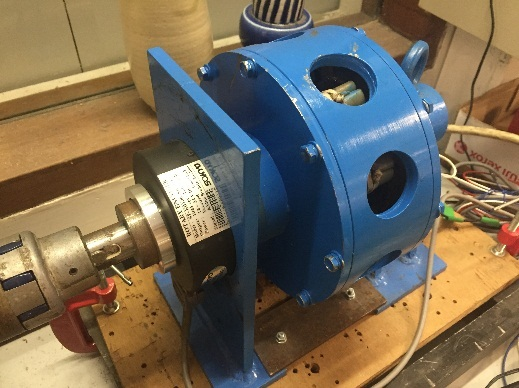
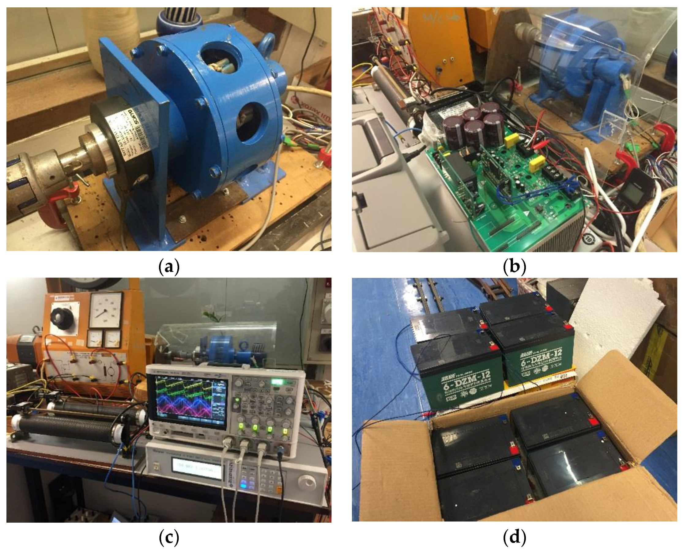
4.1. Proposed Machine and Experimental Setup

Figure 9 shows the AFPM-VM machine and its experimental setup. As shown in the Figure 9a, the proposed AFPM-VM has the hollowed outer rotor to reduce the weight, and this outer rotor structure is suitable for the blade installation in wind generation application. The machine has an optical position sensor, which is used for position estimation confirmation. A TMS320F28335 based convertor is used to drive the AFPM-VM, as shown in Figure 9b. In this paper, a 1.5 kw DC machine is used to simulate the wind turbine which may have blade radius up to 2 meters in such power according to Equation (14), the rotating orientation is counter clockwise seen to the AFVM, and a battery system series by twelve 12 V/6 Ah NI-MH batteries is used for the generation system charging, as shown in Figure 9c,d. The experiment flow chart is shown in Figure 10.
As shown in the Figure 10, a 1.5 kW separately excited DC motor is used to simulate the wind turbine, and the wind speed change is simulated by armature current change. With different armature currents, the carrying load capability of the DC motor changes, which is similar with wind turbine in different wind speeds. The rotor position and shaft speed are estimated by the improved SMO with PLL, as mentioned in Section 3.2. The position is used for the SVPWM control of the generation system and the shaft speed is used by the MPPT strategy calculation. The convertor DC bus links to the battery system, the DC motor drives the generation system and charges the battery system.

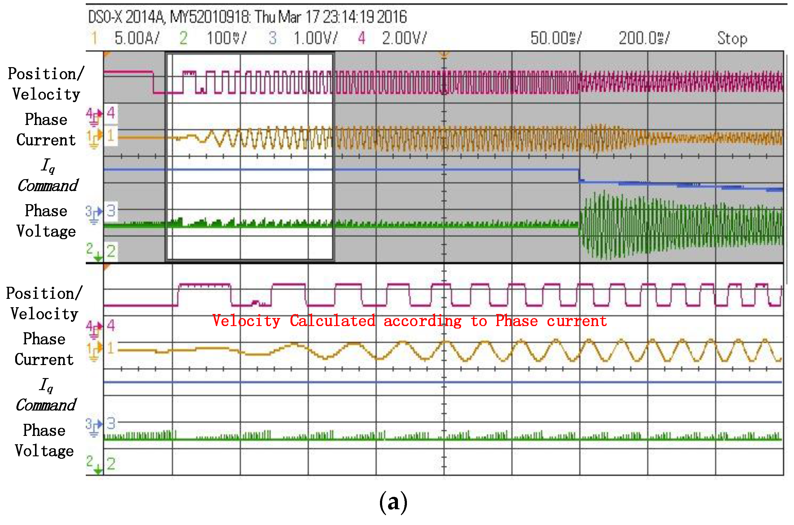
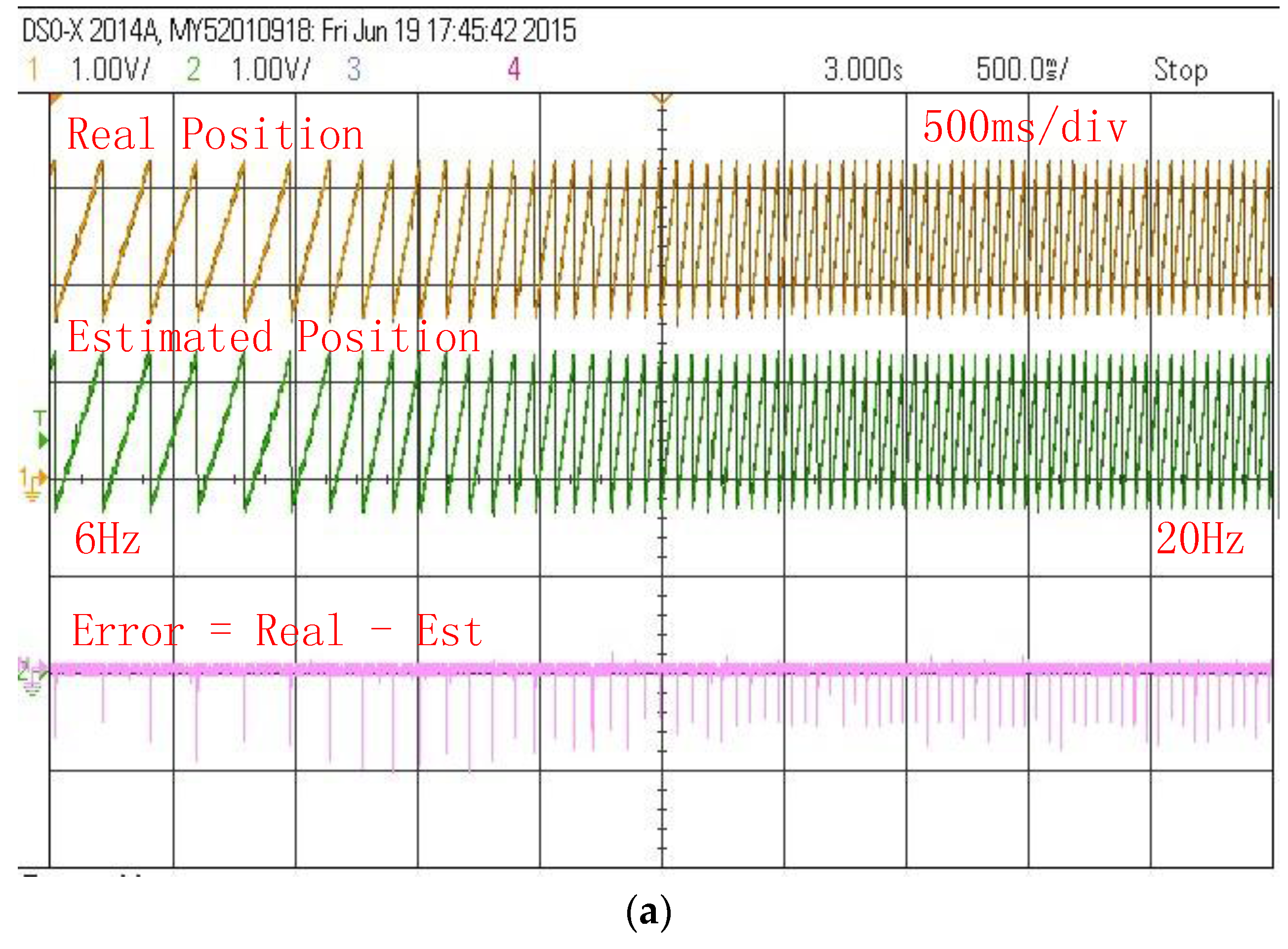
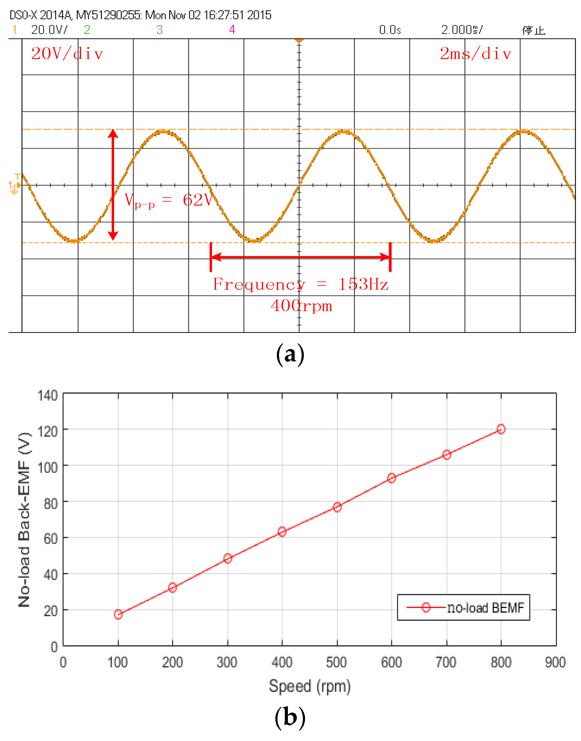
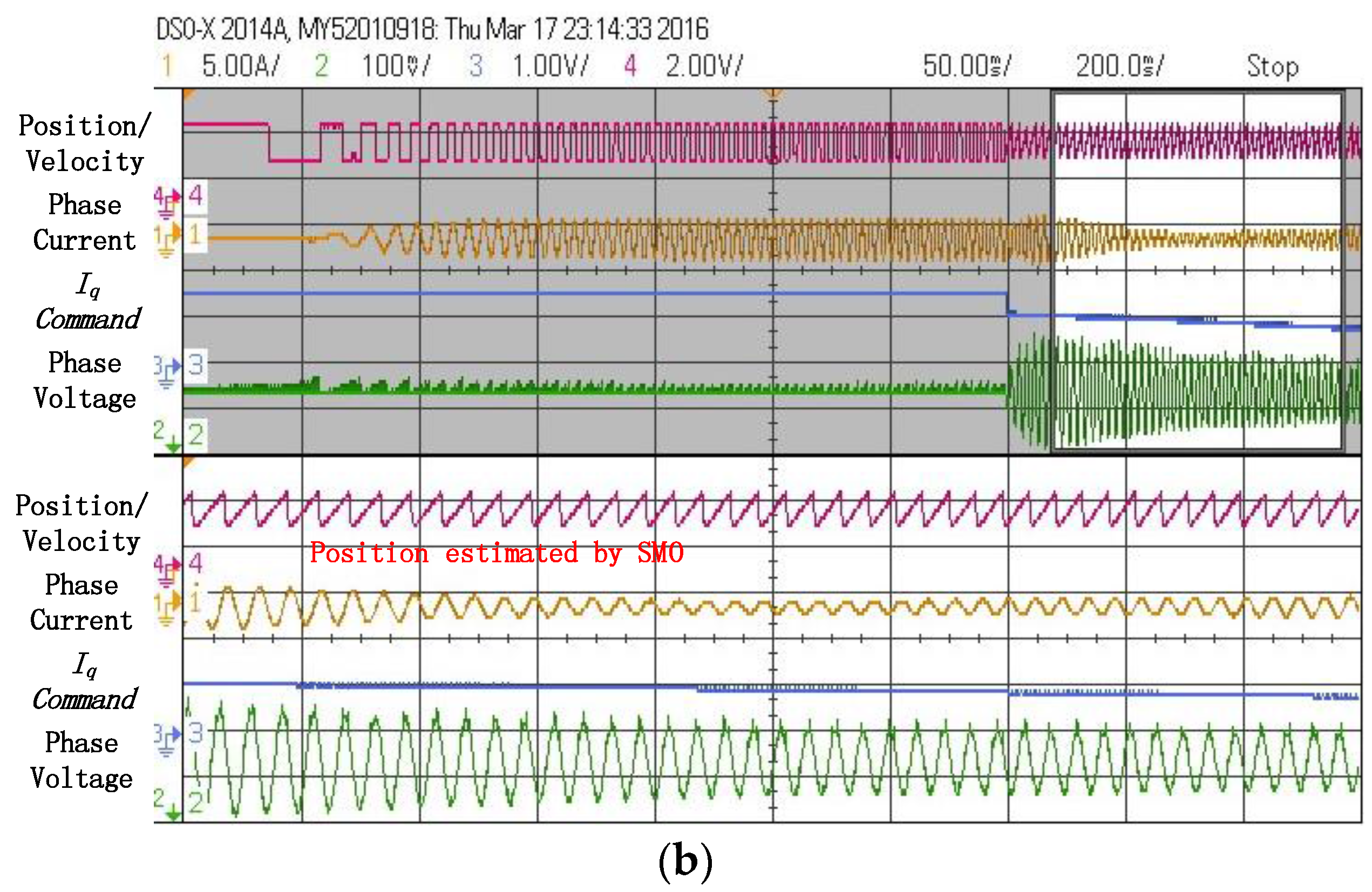
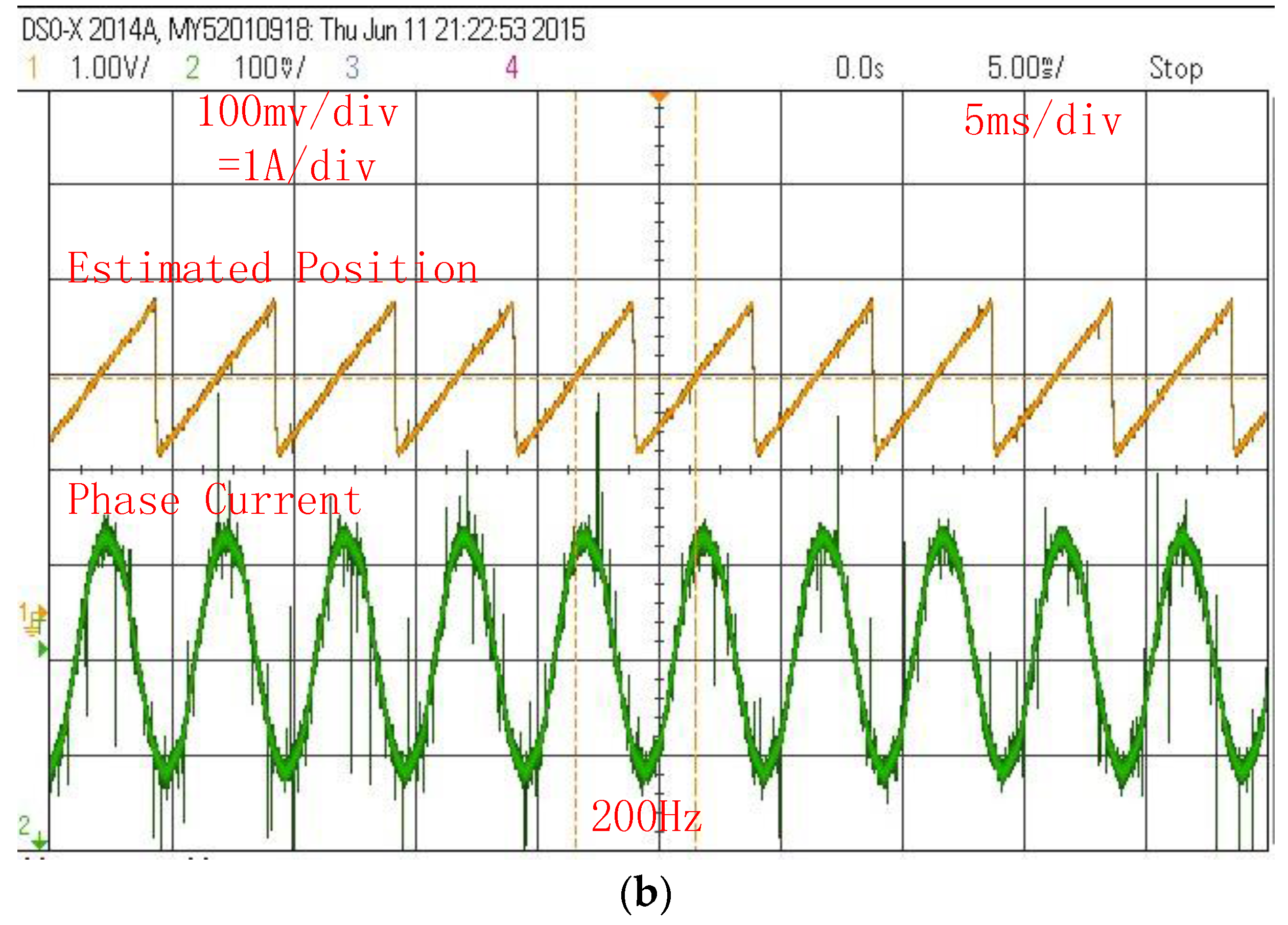
4.2. Machine Design and Position Estimation Verification

The back EMF are shown in the Figure 11, the DC motor is used as the prime mover to drive the proposed AFPM-VM, and the line back-EMFs are recorded by the oscilloscope.
In Figure 11a, line back-EMFs at 400 rpm are recorded with the peak to peak value of the line back EMF of 62V, and thus the phase peak back EMF is 17.9 V, which is consistent with the FEM analysis in Figure 3a. The speed versus back EMF curve in Figure 11b is also consistent with the results in Figure 3b. Figure 12 shows the starting process of the generation system.
As discussed in Section 3.1, the system will not charge the battery system until shaft speed is high enough. The Figure 12a shows that when system starts and shaft speed are low, the breaking resistance connects to the DC bus and expands the uncontrolled generated power, and phase current is recorded to calculated the velocity. When speed is considered as high enough, breaking resistance will be bypassed and system starts to charge the battery system. The position is estimated by using SMO, as shown in Figure 12b.
With the proposed improved SMO, the rotor position can be estimated in a wide speed range. The Figure 13 shows the position estimation results. As shown in the Figure 13a, the estimated stator flux position, the real stator flux position and the estimation error are recorded by the oscilloscope. The estimated stator flux position is related to the rotor position, as discussed in Section 3.2. The real stator flux position is calculated according to the real rotor position, which is measured by the optical position sensor. As discussed in Section 2.3, by introducing the magnetic gear effect, the rotor speed is only 4/23 of the stator flux rotating speed. The frequency of the stator flux is from 6 Hz to 20 Hz, which corresponds to the shaft speed from 15 rpm to 50 rpm as the rotor pole pair number is 23. It can be seen from the figure that the estimation error is very small in this range. A good estimation performance in low shaft speed is of great benefit to direct-drive wind generation application.
In Figure 13b, the stator flux frequency is 200 Hz, which corresponds to the shaft speed at 520 rpm, the phase current shows good sinusoidal performance and the estimation system works well. The performance in Figure 13 shows that the position estimation strategy can works well in the AFPM-VM within a wide speed range.

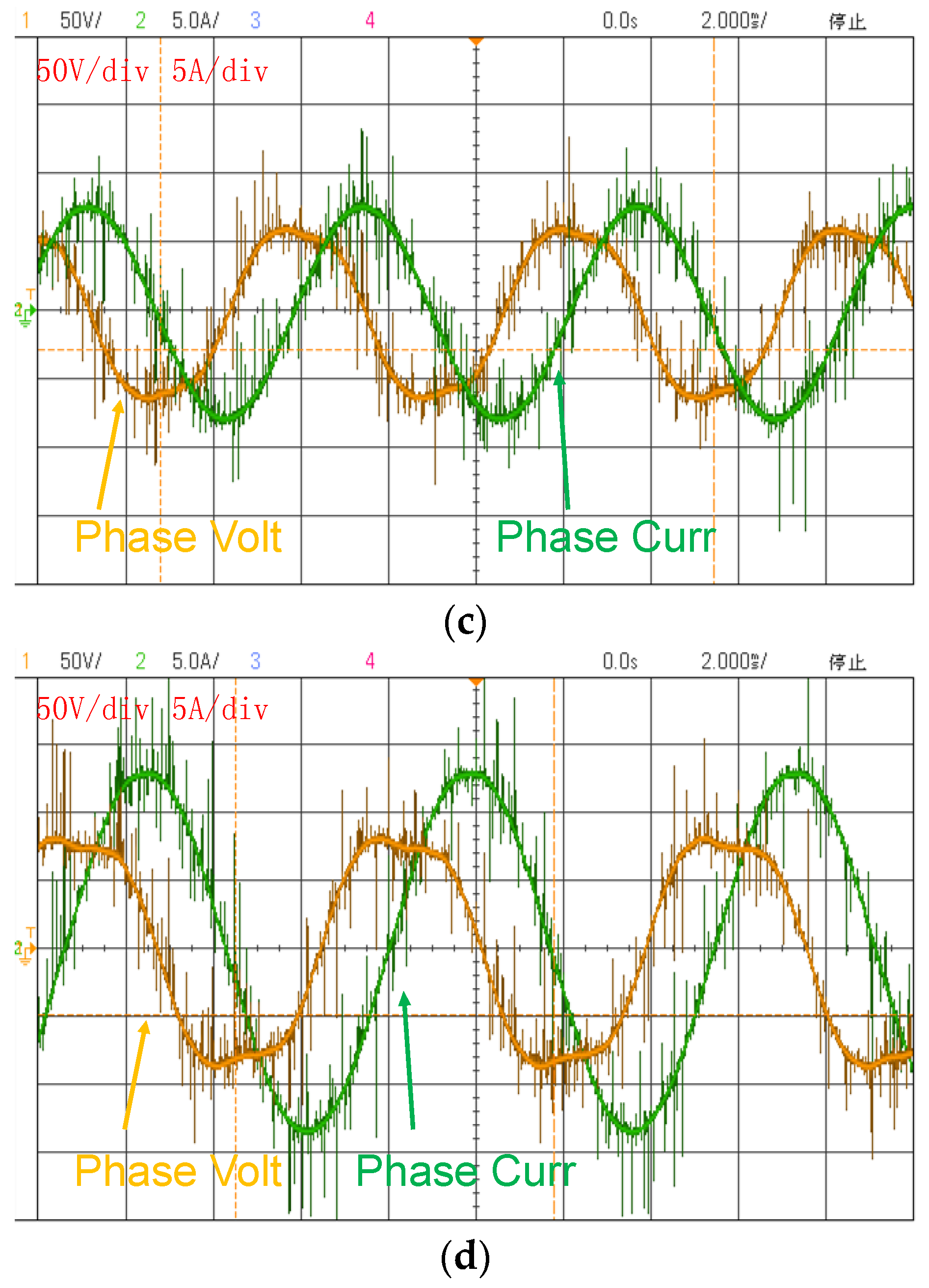
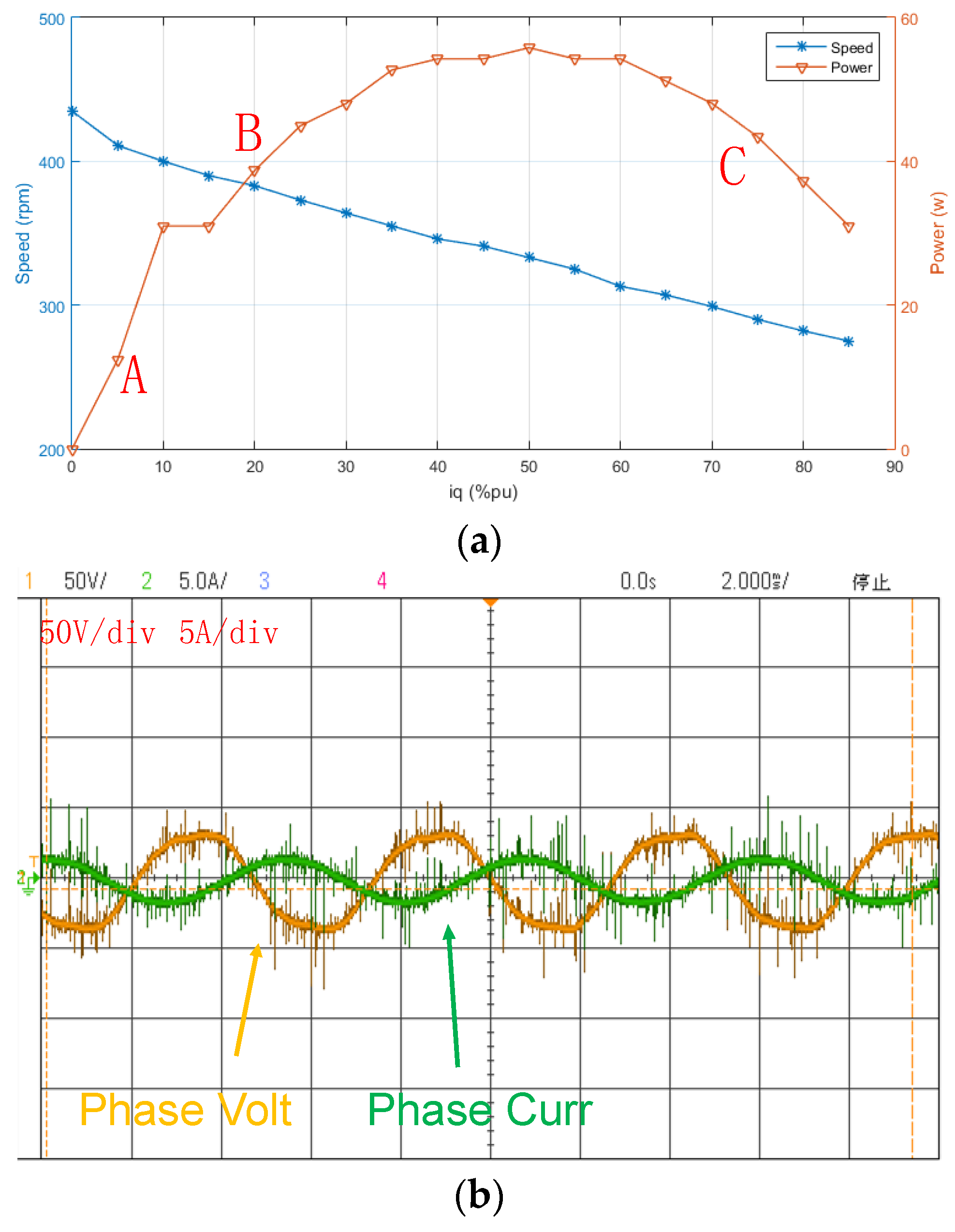
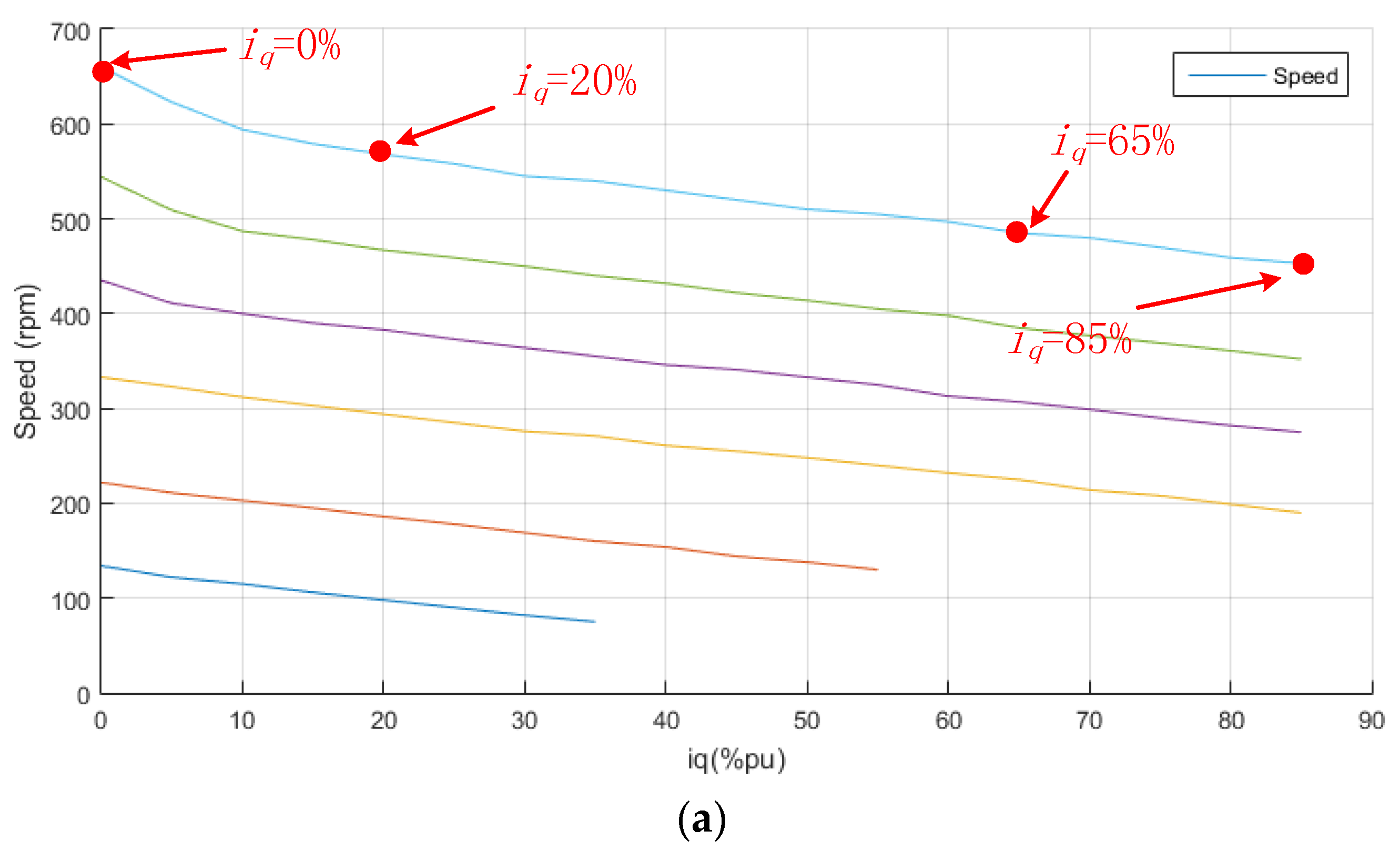
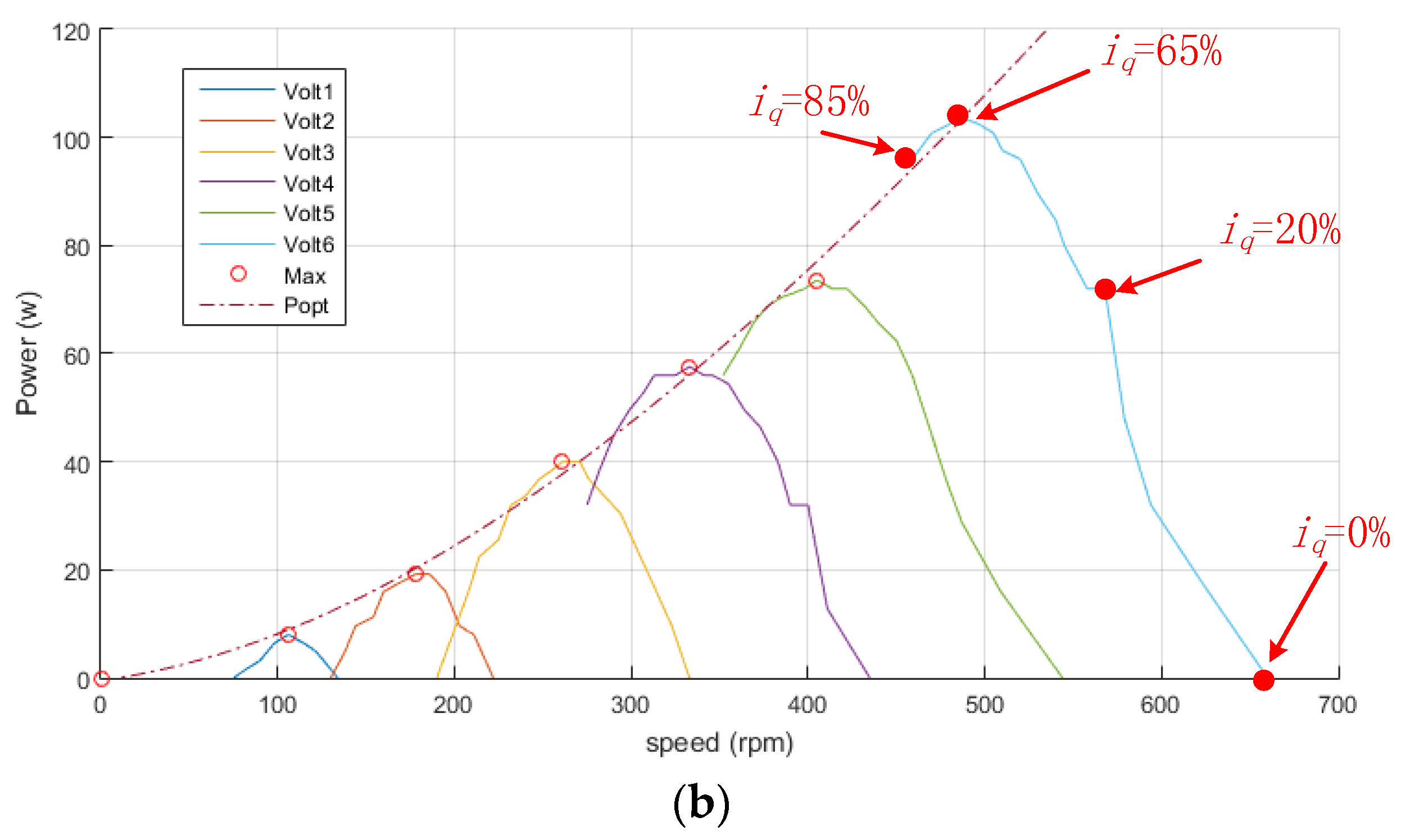
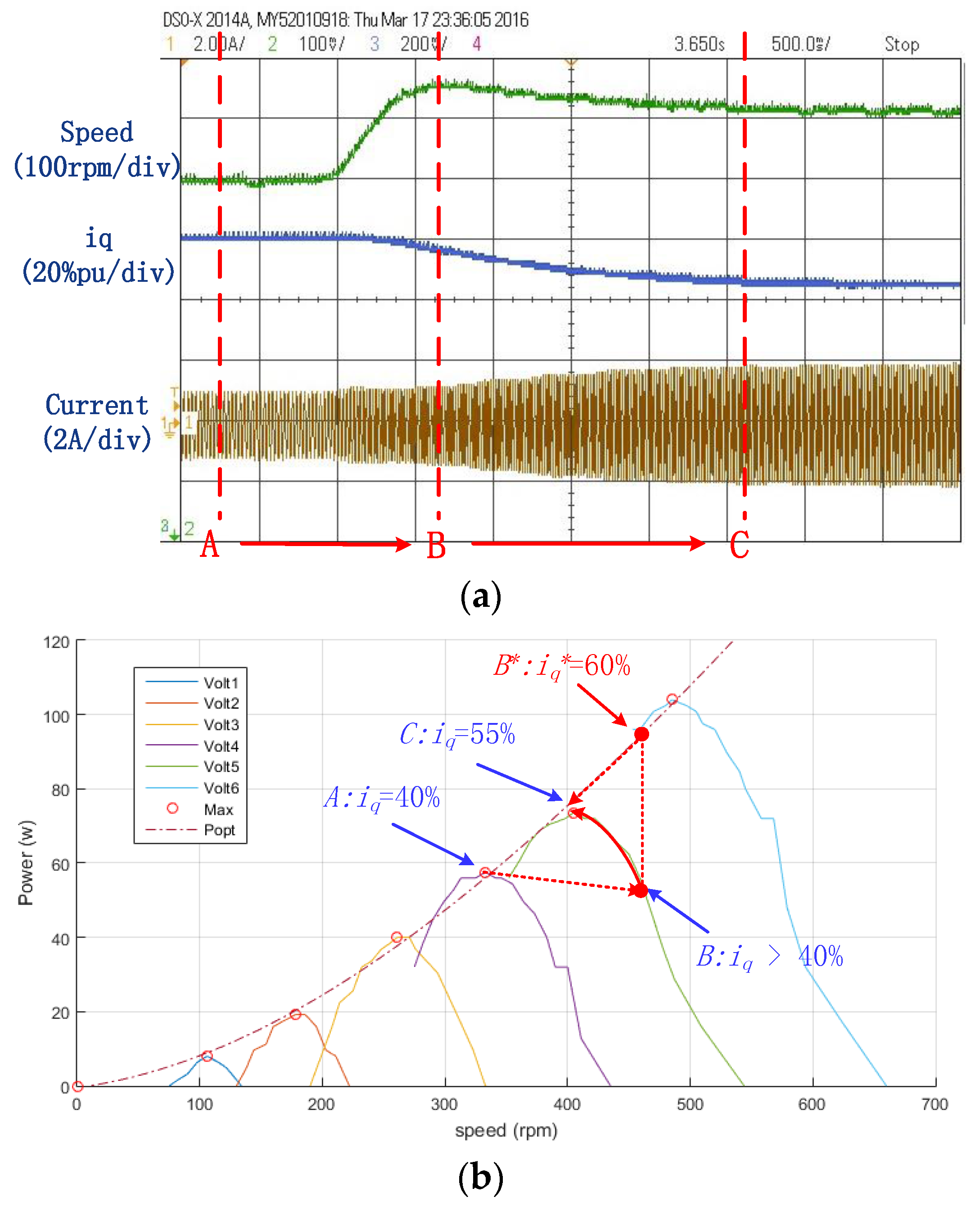
4.3. Sensorless MPPT Control

A 1.5 kW separately excited DC motor is used to simulate the wind turbine, the armature voltage changes to simulate different wind speed. The generation system performance around 400 rpm is shown in Figure 14.
As shown in Figure 14, adjusting the DC motor armature voltage, the system runs at the speed around 400 rpm and then the armature voltage keeps constant. It simulates the wind turbine runs at a constant wind speed. Then adjusting the iq reference value from 0% to 100%, the output power of the system is recorded. It can be seen from the figure that with the increasing iq reference, the output power first increases, and then reaches the max power point. When iq reference is around 50% of the rated value, the output power goes down. The phase current of point A, B and C are recorded by the oscilloscope as shown in Figure 14b–d.
A series of armature voltages are set and the output power of the generation system is recorded, and thus the Popt curve as mentioned in Section 3.2 can be drawn, as shown in Figure 15.
As shown in Figure 15, series of armature voltage are set and with each voltage, the iq command and output power curve like Figure 14a is recorded. The combinations of these curves are shown in Figure 15b. The maximum power points of each curve are linked and the Popt/Topt curve are fitted according to these points, as mentioned in Section 3.2 and drawn in Figure 6. The sensorless MPPT control strategy is verified accordingly. Figure 16 shows a sensorless MPPT control performance of the generation system.
As shown in Figure 16, the shaft speed, the phase current, and iq are recorded by the oscilloscope. It should be noticed that iq is opposite in sign with the speed as it is a generation system. The experiment implements the discussion in Figure 7 (point C to F), and the point A in Figure 16 is the same with the point C in Figure 7.
At point A, iq and its reference value are both 40% pu, the system runs at a lower speed and keeps stable. Then the armature voltages increase, which simulates the increasing wind speeds. From point A to B, iq almost keeps constant as the effect of the sluggish unit, and thus the torque generated by the generation system changes slowly, which makes the shaft speed go up and the system reaches point B. At point B, torques generated by the DC motor and the generation system equals to each other, the shaft speed reaches its maximum value. At this time, iq reference is set to 60% pu due to the Popt curve marked as B* in the figure, which is greater than that in the point C, shaft speed starts to go down. The iq reference goes down as speed goes down, and equals to the real value of iq at point C. from point B to C, the real value of iq continues to go up, trying to catch the reference value. The shaft speed at C point is higher than A, but lower than B. However, it has the largest phase current, which reflects the highest output power.

5. Conclusions

In this paper, an AFPM-VM is proposed for direct-drive wind power generation application. By introducing the magnetic gear effect in the machine design, generation system is very suitable for low-speed high-torque direct drive operation. The outer rotor allows for direct coupling with the wind turbine, thus alleviating the bearing requirements and improving the mechanical integrity.
The sensorless MPPT control strategy for the new AFPM-VM is discussed in the paper. With an improved SMO with PLL, the rotor position and shaft speed are accurately estimated, which establishes the control basis for the MPPT control strategy. The sensorless MPPT control strategy is verified by experiments with a DC motor simulating the wind turbine.

Acknowledgments

This work was supported by research grants PolyU 152130/14E of the Research Grants Council in the Hong Kong Special Administrative Region, China.

Author Contributions

Shuangxia Niu conceived of the idea of the research and provided guidance and supervision. Xiang Luo implemented the research, performed the analysis and experimental verification. All authors have contributed significantly to this work.

Conflicts of Interest

The authors declare no conflict of interest.

References

  1. Niu, S.; Ho, S.L.; Fu, W.N. A Novel Direct-Drive Dual-Structure Permanent Magnet Machine. IEEE Trans. Magn. 2010, 46, 2036–2039. [Google Scholar] [CrossRef]
  2. Atallah, K.; Howe, D. A novel high-performance magnetic gear. IEEE Trans. Magn. 2001, 37, 2844–2846. [Google Scholar] [CrossRef]
  3. Niu, S.; Chen, N.; Ho, S.L.; Fu, W.N. Design Optimization of Magnetic Gears Using Mesh Adjustable Finite-Element Algorithm for Improved Torque. IEEE Trans. Magn. 2012, 48, 4156–4159. [Google Scholar] [CrossRef]
  4. Ho, S.L.; Niu, S.; Fu, W.N. Design and Comparison of Vernier Permanent Magnet Machines. IEEE Trans. Magn. 2011, 47, 3280–3283. [Google Scholar] [CrossRef]
  5. Li, J.; Chau, K.T.; Jiang, J.Z.; Liu, C.; Li, W. A New Efficient Permanent-Magnet Vernier Machine for Wind Power Generation. IEEE Trans. Magn. 2010, 46, 1475–1478. [Google Scholar] [CrossRef] [Green Version]
  6. Zhao, Y.; Zhang, Z.; Qiao, W.; Wu, L. An Extended Flux Model-Based Rotor Position Estimator for Sensorless Control of Salient-Pole Permanent-Magnet Synchronous Machines. IEEE Trans. Power Electr. 2015, 30, 4412–4422. [Google Scholar] [CrossRef]
  7. Kommuri, S.K.; Veluvolu, K.C.; Defoort, M.; Soh, Y.C. Higher-Order Sliding Mode Observer for Speed and Position Estimation in PMSM. Math. Probl. Eng. 2014, 2014, 1–12. [Google Scholar] [CrossRef]
  8. Khlaief, A.; Boussak, M.; Châari, A. A MRAS-based stator resistance and speed estimation for sensorless vector controlled IPMSM drive. Electr. Power Syst. Res. 2014, 108, 1–15. [Google Scholar] [CrossRef]
  9. Yuan, Q.; Yang, Z.; Lin, F.; Sun, H. Sensorless Control of Permanent Magnet Synchronous Motor with Stator Flux Estimation. J. Comput. 2013, 8, 108–112. [Google Scholar] [CrossRef]
  10. Jouili, M.; Jarray, K.; Koubaa, Y.; Boussak, M. Luenberger state observer for speed sensorless ISFOC induction motor drives. Electr. Power Syst. Res. 2012, 89, 139–147. [Google Scholar] [CrossRef]
  11. Bernardes, T.; Montagner, V.F.; Grundling, H.A.; Pinheiro, H. Discrete-Time Sliding Mode Observer for Sensorless Vector Control of Permanent Magnet Synchronous Machine. IEEE Trans. Ind. Electron. 2014, 61, 1679–1691. [Google Scholar] [CrossRef]
  12. Feng, Y.; Yu, X.; Han, F. High-Order Terminal Sliding-Mode Observer for Parameter Estimation of a Permanent-Magnet Synchronous Motor. IEEE Trans. Ind. Electron. 2013, 60, 4272–4280. [Google Scholar] [CrossRef]
  13. Qiao, Z.; Shi, T.; Wang, Y.; Yan, Y.; Xia, C.; He, X. New Sliding-Mode Observer for Position Sensorless Control of Permanent-Magnet Synchronous Motor. IEEE Trans. Ind. Electron. 2013, 60, 710–719. [Google Scholar] [CrossRef]
Figure 1. Structure of the proposed machine.
Energies 09 00581 g001
Figure 2. Flux density on the surface of one side of the stator.
Energies 09 00581 g002
Figure 3. FEM analysis results. (a) No-load back-EMFs at 400 rpm; (b) Peak values of the back-EMFs.
Energies 09 00581 g003
Figure 4. Hardware setup for testing the proposed AFMM-VM.
Energies 09 00581 g004
Figure 5. Improved sliding mode observer (SMO) flow chart.
Energies 09 00581 g005
Figure 6. Power captured in different rotating speeds and wind speeds.
Energies 09 00581 g006
Figure 7. Maximum power point tracking (MPPT) control strategy.
Energies 09 00581 g007
Figure 8. MPPT control strategy.
Energies 09 00581 g008
Figure 9. Proposed AFPM-VM and experimental setup. (a) Proposed machine; (b) Convertor used to drive the AFPM-VM; (c) DC machine, Oscilloscope and the DC power supply; (d) Battery system.
Energies 09 00581 g009
Figure 10. Experiment flow chart.
Energies 09 00581 g010
Figure 11. AFPM-M back EMF. (a) Line back EMF at the speed of 400 rpm; (b) Peak-peak value of the line back EMF from 100 rpm to 800 rpm.
Energies 09 00581 g011
Figure 12. Starting process of the generation system. (a) When shaft speed is below the threshold; (b) When speed goes up through the threshold.
Energies 09 00581 g012aEnergies 09 00581 g012b
Figure 13. Rotor position estimation results. (a) Real position versus estimated position in transient speed change; (b) Estimated position and phase current in steady state performance.
Energies 09 00581 g013aEnergies 09 00581 g013b
Figure 14. Generation system performance around 400 rpm. (a) DC motor speed, iq command value and system output power; (b) Phase voltage and current at point A; (c) phase voltage and current at point B; (d) Phase voltage and current at point C.
Energies 09 00581 g014aEnergies 09 00581 g014b
Figure 15. Maximum power point curve of the experiment generation system. (a) Shaft speed curve with different armature voltage and i q ; (b) Popt curve of the sytem.
Energies 09 00581 g015aEnergies 09 00581 g015b
Figure 16. Sensorless MPPT control performance. (a) Speed, phase current and i q * curves; (b) MPPT Control strategy.
Energies 09 00581 g016
Table 1. Specifications of the proposed axial-flux permanent magnet machine (AFPM-VM).
ParameterValue
Input voltage (V)155
Rated torque (Nm)4
Rated speed (rpm)400
Outer diameter of rotor (mm)60
Inner diameter of rotor (mm)20
Outer diameter of stator (mm)60
Inner diameter of stator (mm)35
Stator thickness (mm)50
Axial length of rotor PMs (mm)25
PM thickness (mm)3
Air-gap (mm)1
Turn number per phase45
Rotor pole-pair number23
Stator pole-pair number4
Stator fake tooth number27

