1. Introduction
Improving wind turbine (WT) reliability is crucial for reducing the cost of wind energy. Direct drive WTs with Permanent Magnet Synchronous Generators (PMSGs) are expected to achieve high reliability by eliminating the gearbox which potentially cause long downtime for gear-drive WTs [
1]. However, reliability analysis of wind turbine subassemblies shows that the power converters of direct drive WTs exhibit higher failure intensities than those in other industries [
2]. Early failure of converters is the main issue for large size WTs that is mostly used at offshore applications [
3]. The current strategies to improve the reliability and availability of power electronic system include condition monitoring, prognosis, redundancy and fault tolerant operation [
4], which essentially relies on an accurate fault diagnosis of power electronic components.
Two main types of switch failures in converters are short-circuit and open-circuit [
5]. Short-circuit failures lead to destructive consequences so that any protection system should respond by shutting down the system. While the drive system can continuously operate under open-circuit failure conditions with degraded performance, subsequent unstable rotational speeds and loads will be encountered in the generator and this may lead to further damage to the system. Therefore, fault detection and diagnosis is necessary for open-switch failures. A variety of techniques are applied to detect open-circuit faults, which are reviewed in [
6,
7]. They include: Errors of Normalized Currents Average Absolute Values (ENCAAV), Current Park Vector Phase and Current Polarity (CPVPCP), Normalized Current Average Values (NCAV), the Normalized Reference Current Errors (NRCEs). The methods mentioned are based on Park’s vector approach which normalizes phase currents against a reference/average/average absolute current to reflect the deviation of the current from the expected value. A parameter quantifying the errors of the normalized results is defined to detect single or multiple converter failures. Another Park’s Vector based fault diagnosis approach is through identifying three phase current signature patterns [
8]. It is demonstrated in AC-DC pulse width modulated (PWM) converter fault detection by observing the variation of the current angle [
5,
9].
The fault detection methods above are proposed for converters in traditional motor drive applications. Recent researches have been extended to consider the fault diagnosis problem of converters in wind turbine systems. For example, a new data mining approach is proposed by monitoring drifts of converters for its early faults diagnosis [
10,
11]. A voltage-based detection approach was developed for online faulty switches identification [
12]. Transient loads due to fast wind variation and turbulence, abrupt torque changes due to WT response both cause complexity of converter fault diagnosis of WTs. However, current diagnostic methods proposed for generator-side converters of WT considering the transient wind speed variation and control system impacts are rare. The Park’s vector modulus normalized approach [
13] and the neural network for faulty switch patterns recognition [
14] for WT generator-side converters may not be applicable in fast wind variation situations. Intelligent fault diagnosis for WT converters with certain control schemes and under random wind speed conditions is a challenging problem.
To fully understand the challenge of WT converter fault diagnosis, this paper firstly studies their impacts of wind speed and control scheme on converter fault diagnosis through a PMSG WT simulation model and emphasize the generator-side converter. A four component wind speed model is constructed to simulate wind variety. For WT generator-side Maximum Power Point Tracking (MPPT), a zero d-axis current control strategy is used to generate control signals for the SVPWM converter. Open-circuit fault features of a representative case of WT generator side converters are analyzed. Challenges of using normalized current approach and vector pattern recognition for converter fault diagnosis are illustrated. This paper secondly proposed a new fault diagnosis method namely Wind Speed Based Normalized Current Trajectory (WSBNCT) for WT PMSG machine-side converter open-circuit fault diagnosis. Its fault detection capability is investigated through simulation and experiments. Such a method is finally evaluated and summarized in terms of its capability and robustness for accurate fault diagnosis under noisy variable wind conditions.
2. PMSG Wind Turbine System Simulation
2.1. Wind Speed Simulation
As WTs operate under variable wind conditions, a sound stochastic wind model presenting a realistic variety of winds is a premise for WT system simulation. The wind speed signal is composed by four components: mean wind speed
vm, wind speed ramp
vr, wind gust
vg and turbulence
vt [
15]:
where mean wind speed is a constant reflecting the average wind speed scale:
Wind ramp represents the slow variation component of wind speed, which is characterized by three parameters: wind ramp maximum amplitude
Ar (m/h), wind ramp starting time
Tsr (s), wind ramp maximum time
Ter (s) in Equation (3):
Wind gust is defined by three parameters: wind gust amplitude
Ag (m/h), wind gust starting time
Tsg (s), wind gust end time
Teg (s) as shown in Equation (4):
Dg is the wind gust duration.
Wind turbulence is modeled by its spectral density which essentially presenting the random noisy component of wind speed:
where
f is the frequency (Hz);
h is the height at which the wind speed signal is measured (m), which normally equals the height of the wind turbine shaft;
is the mean wind speed (m/s);
l is the turbulence length scale (m) which equals 20 if
h is less than 30 m and 600 if
h is more than 30 m; and
z0 is the roughness length (m).
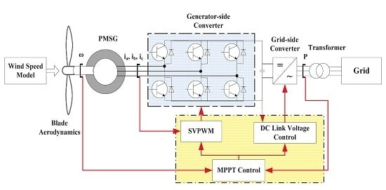
2.2. PMSG Wind Turbine Simulation
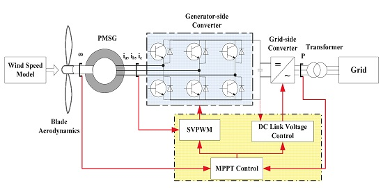
The configuration of a PMSG wind turbine system is illustrated in
Figure 1. Back-to-back voltage source converters are used to interface the PMSG with the grid.
According to the WT blade aerodynamics [
16], the wind power captured by a wind turbine is modeled by:
where ρ is the air density (kg/m
3),
R is turbine radius (m),
V is wind speed (m/s),
Cp(β,λ) is the turbine power coefficient that describes the WT power extraction efficiency and it is a function of tip-speed-ratio and the blade pitch angle. It can be calculated using the equation below [
17]:
where β is the blade pitch angle, and other parameters can be empirically determined and adjusted according to the actually blade model.
When the turbine is operating above rated wind speed, the system controls the pitch angle to limit the mechanical energy into the WT, while when it is operating under rated wind speed, the WT is controlling the rotational speed of the mechanical shaft through making the generator produce reversion torque under either speed or torque control mode. The desired rotational speed is determined by maximum
Cp value where the tip-speed-ratio reaches the optimal value for each wind speed. This is the principle of the MPPT control strategy for WTs. The resulting optimal power delivered by the WT has a relationship with the rotor speed, which can be described by:
where
k is a coefficient can be calculated as:
where λ
opt is the optimal tip-speed-ratio that is often provided by the wind turbine manufacturers and
cpopt is optimal wind energy utilization coefficient.
2.3. PMSG Control Logic
Back-to-back voltage source converters [
18] of a wind turbine include generator-side and grid-side converters. Generator-side converter is to control the PMSG as response of wind turbine MPPT strategy that to maximize active power. Grid-side converter is to maintain constant grid voltage by adjusting zero reactive power, which is equivalent to a regulated power supply subsystem according to the functional analysis as shown in
Figure 1 [
19].
PMSG generator stator voltage in the rotating coordinate system voltage is expressed in the following equations:
where subscripts
d,
q are referring to the corresponding parameters in the
d-
q axis that are transferred from three phase parameters in which
u is the equivalent voltage;
i is the equivalent currents; ψ is the equivalent flux and
L is the stator inductance of PMSG.
R is stator phase resistance; ψ
f is the flux of the permanent magnets; ω
e is the electrical angular speed which can be expressed as follows:
The electrical torque of the three-phase PMSG can be calculated by formula:
With zero
d-axis current control strategy, generator electromagnetic torque has linear relationship with stator
q-axis current. Therefore, generator electromagnetic torque equation can be written as:
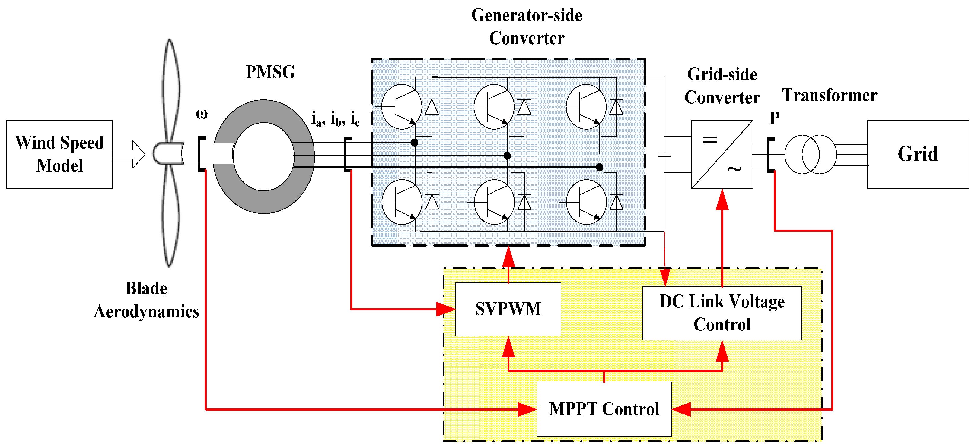
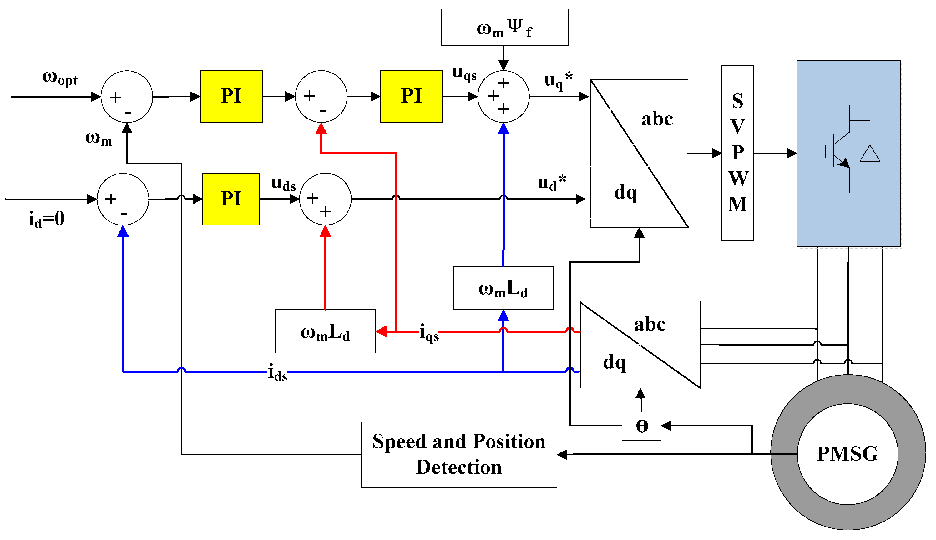
SVPWM converter control model is shown in
Figure 2 [
19].
WT optimal rotational speed ω
opt is determined by optimal tip-speed-ratio and the wind speed
V as shown in Equation (14):
As shown from Equations (10)–(13) and in
Figure 2, the generator electromagnetic torque is determined by the magnetic flux and the stator current (
id,
iq). By controlling the
q-axis stator current the rotational speed of the generator can be controlled, while the
d-axis stator current is kept at zero in order to ensure reactive power control. Their coupling effects are considered through voltage compensation, so the measured generator torque is compared to the optimal rotational speed to generate suitable SVPWM signals for the generator-side converter in order to realize the MPPT control strategy. Once a fault occurs in the generator-side converter, the generator speed will become unstable and the resultant stator currents deviate from the desired value. In addition, as the wind speed varies simultaneously the converter fault diagnosis needs to distinguish between abnormal symptoms from the nonlinear response of control system and wind speed fluctuations.
2.4. Generator-Side Converter SVPWM Control Strategy
The three phase voltage of converter can be expressed as Equation (15), where
um is the amplitude and ω is the space vector’s frequency. Park transformation (or
abc/
dq) is applied to transform the three phase voltage into two phase frame vector
ud,
uq with Equation (16). The desired vector
ud,
uq are given by the PI controller. Then the voltage vector can be determined by Equation (17). PWM signals for the converter are generated [
9] based on the space vector as illustrated in
Figure 3 [
20]. The resulted vector is obtained by adjusting the eight basic vectors from
u0 to
u7 that are adjacent to the desired voltage vector with Equation (18).
Faults occurring in the switches of converters will lead to dislocation of the resulting voltage vector. The phase currents are the common measurable quantities, based on which most fault detection algorithms are developed.
3. Fault Diagnostic Method
Open-circuit is the main failure mode of concern for converters [
12]. Fault diagnosis methods for such failure mode are classified into two types: direct current detection and current park vector/trajectory recognition. The first type detects failures by defining characteristic parameters that are obtained through processing the corresponding current signals. These include the approaches named NCAV, ENCAAV and NRCEs mentioned in the previous sections [
6]. The second type is to detect faults by the current’s Park vector pattern recognition, which may use neural networks for the pattern recognition [
15]. Although the methods are applicable to most variable speed drive systems, its effectiveness for wind turbine converters under transient wind speed conditions is not fully investigated. The impacts of nonlinear control system response and wind turbulence to converter fault diagnosis are studied in this section. A new diagnosis method is then proposed and its effectiveness and robustness are compared.
3.1. Direct Current Detection Method
NCAV, ENCAAV and NRCEs use a current’s park vector to detect and localize converter faults [
6]. As a representative example, the ENCAAV method is analyzed here. The ENCAAV method detects faults by defining errors of normalized phase currents to modulus of currents’ Park vector with Equations (19)–(21).
Similar to voltage park transformation, the measured motor phase currents (
ia,
ib,
ic) can be transferred to the
d-
q axis as shown in Equation (19):
Modulus of the current park’s vector is calculated in Equation (20):
Each phase current is normalized to the modulus and errors of the normalized phase currents’ average absolute value is defined as:
ξ is an empirical constant defined for different application [
6].
en is the characteristic parameter of each phase (index as
n). It is defined to detect and localize switch failures. Its capability for wind turbine converter open-circuit fault detection is investigated in a later section.
3.2. Current Vector/Trajectory Pattern Recognition
This method Current Vector/Trajectory Pattern Recognition (CVTPR) is also based on current’s park vector transformation as shown in Equations (19) and (20). The vector’s angle is calculated by:
The modulus of current vectors is the radius and θ is the vector’s angle in
d-
q axis space. The patterns of the current vector in a complete period are used to identify open-circuit faults [
15].
3.3. Comparison of the Two Diagnostic Methods
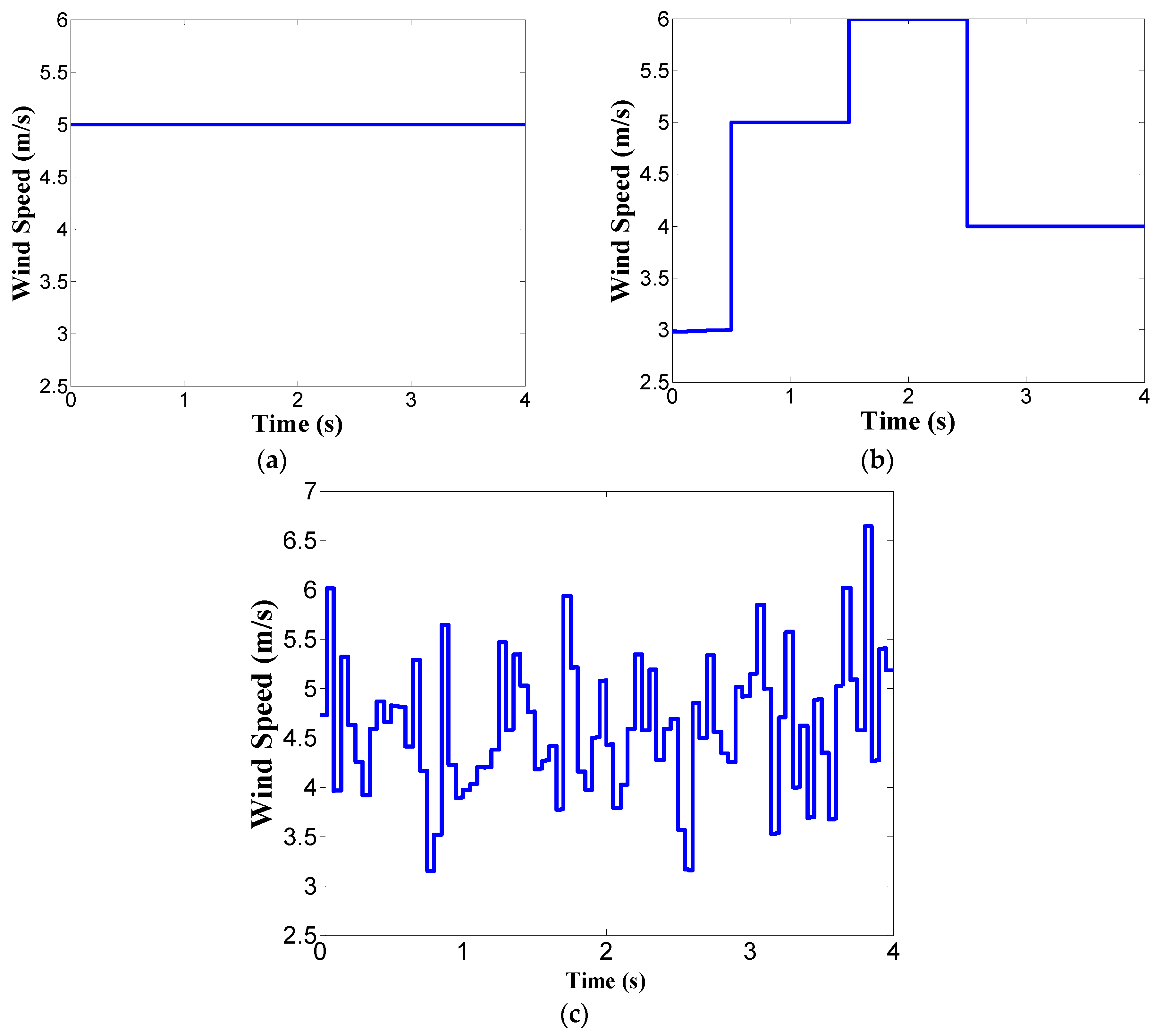
The diagnostic capability of the two approaches to detect wind turbine converter faults under constant, step and turbulent wind are investigated and compared. A simulation model is developed using Matlab Simulink. A 30 kW PMSG WT with the parameters listed in
Table 1 is simulated. The wind speed situations are shown in
Figure 4.
Figure 4a shows the constant wind speed at 5 m/s.
Figure 4b shows the step wind ranging from 3 to 6 m/s with certain wind speed last for one or two seconds.
Figure 4c shows turbulent wind being characterized by its average wind speed of 5 m/s and turbulent scale of 0.1–0.2.
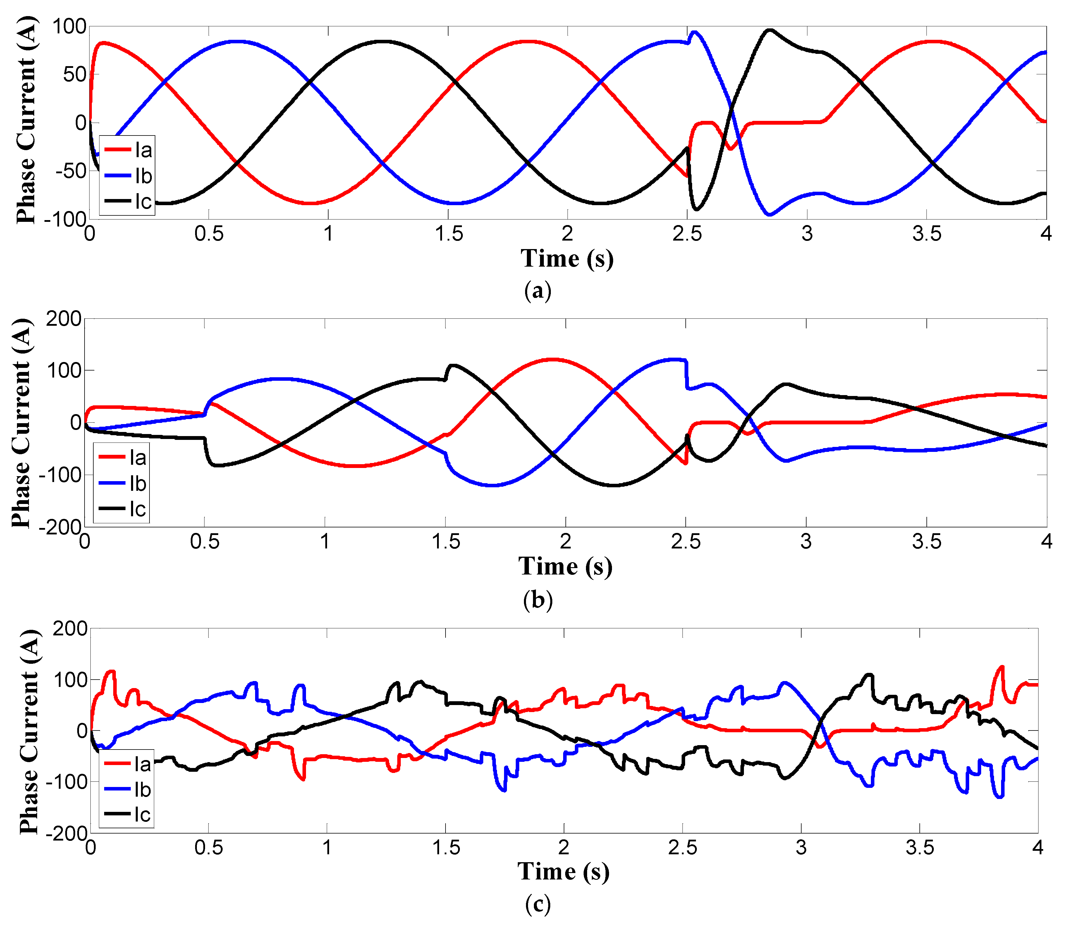
Open-circuit faults of T1 switches of the converter as shown in
Figure 3 are introduced at 2.5 s. Three phase currents of generator-side converter are shown in
Figure 5. It shows that the current distortion of the converter under constant wind can be easily identified, while for the step and turbulent wind situation, the identification of current distortion in the time domain becomes difficult.
The fault diagnostic results of applying the ENCAAV and CVTPR methods are shown in
Figure 6.
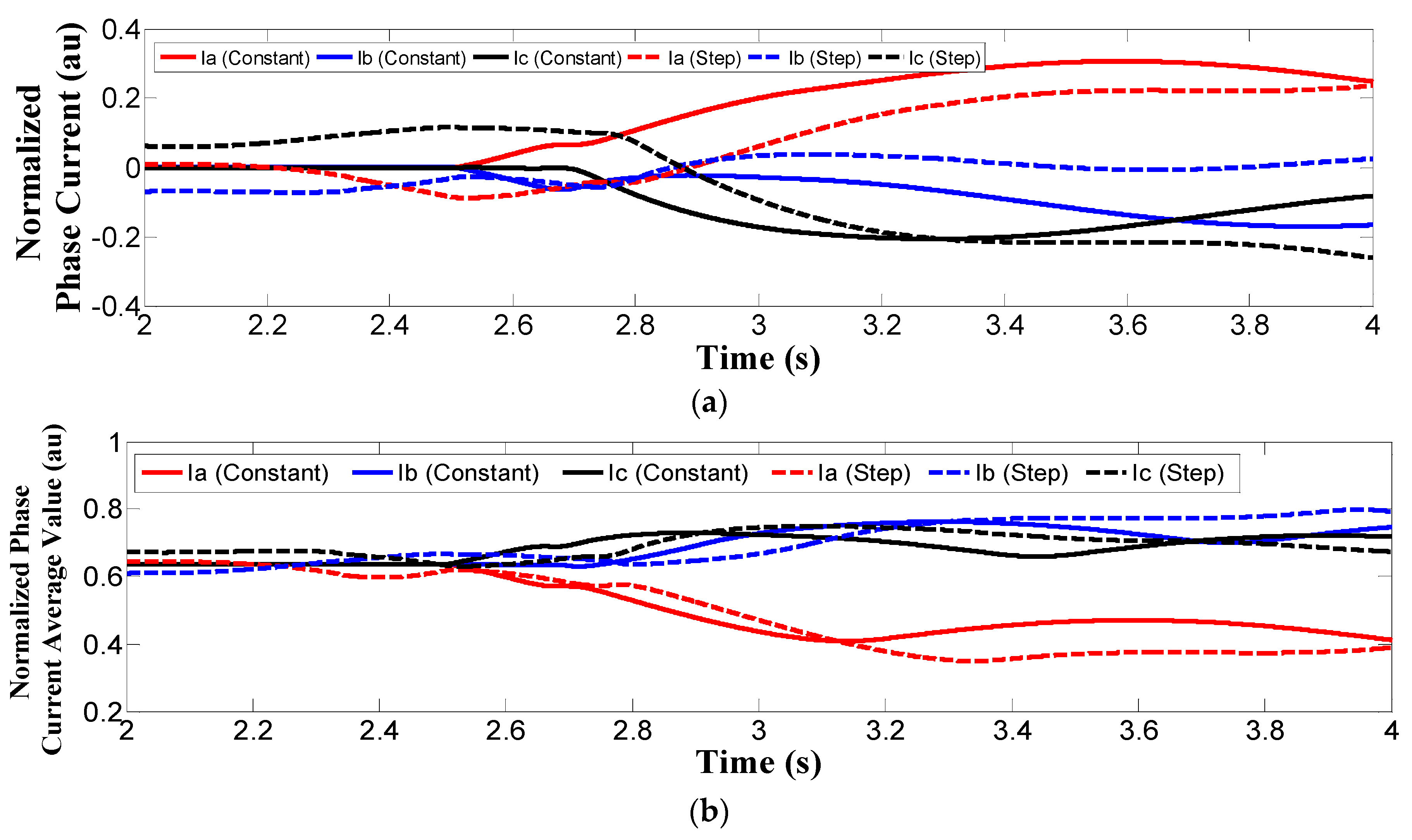
Figure 6a,b shows the result of normalized phase currents |
in/|
is|| and normalized phase current average value <|
in/|
is||> respectively for constant wind and step wind situations. They are two critical fault diagnostic parameters in the ENCAAV method. From
Figure 6, it can be confirmed that with these two parameters, converter faults can be detected for a constant wind situation while it is not valid for step winds. It clearly shows that under step wind conditions the diagnostic parameters of the ENCAAV method deviate from zero under heathy situation. Such a deviation is actually caused by wind speed variation and may lead to false alarms.
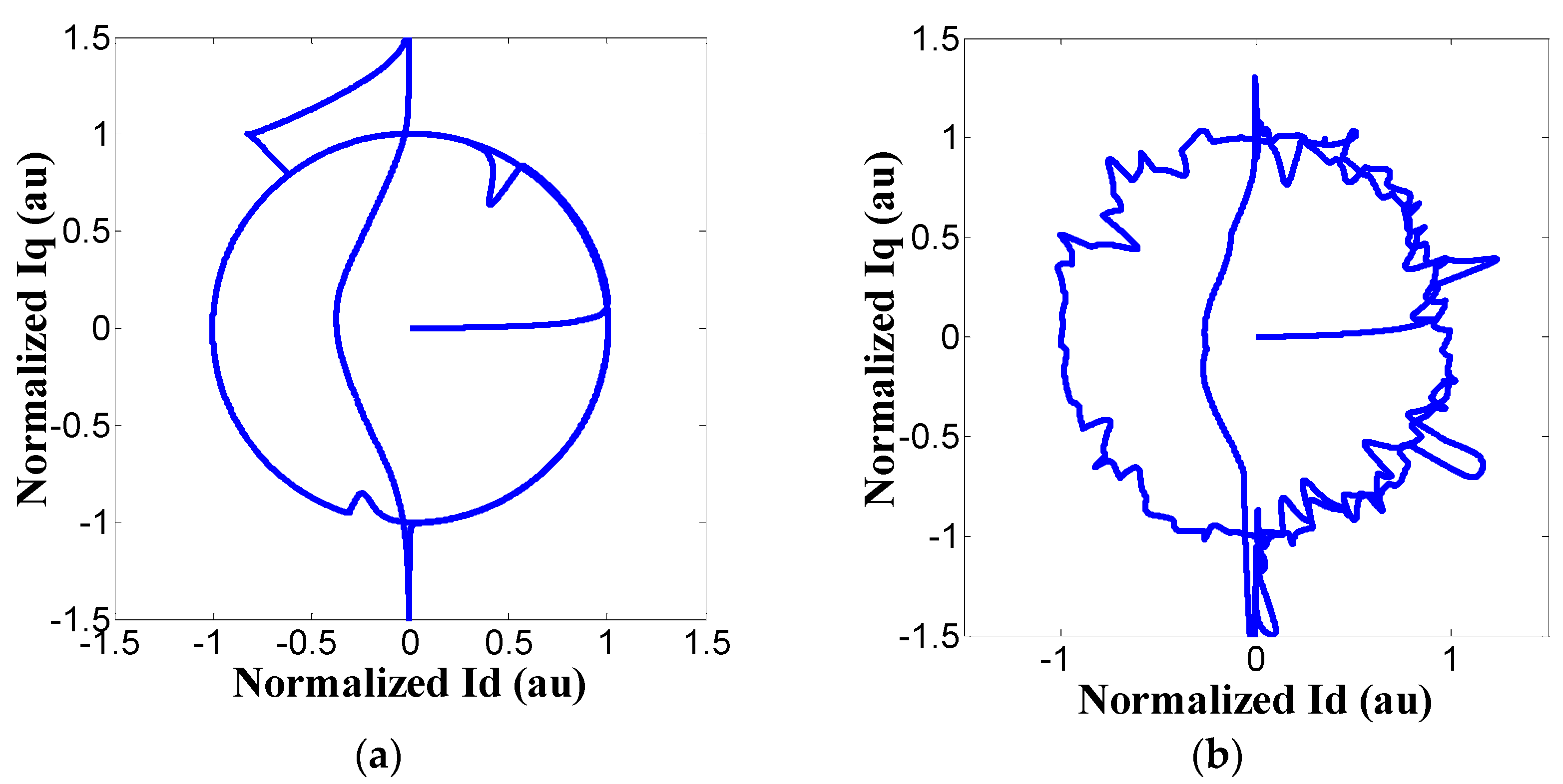
Figure 6c,d show the diagnostic result of using the CVTPR method for step wind and turbulent wind, respectively. Wind speed variation also leads to untraceable pattern when faults occur. The comparison shows that current pattern recognition methods become invalid for step wind and turbulent wind situations.
ENCAAV and CVTPR methods are both effective under constant wind conditions while their fault detection capabilities become invalid for WT in turbulent wind situations. The ineffectiveness of the two methods is due to the stochastic wind speed causing uncertain three phase currents’ periods and unstable values of the current magnitude. For the ENCAAV method, the measured current must complete one period to obtain an average value of the normalized currents. The current’s period uncertainty leads to inapplicability of the average operation. By evaluating its fault detection accuracy, robustness and adaptability, ENCAAV is not a good solution for WT converter fault detection. On the other hand, the instability of current magnitude will lead to untraceable patterns due to unexpected current values of the open-circuit converter and thus invalidate the CVTPR method.
3.4. Wind Speed Based Normalized Current Trajectory Detection
To overcome the difficulty of stochastic wind speed-caused uncertainty, a wind speed-based normalized current trajectory (WSBNCT) method is proposed for a wind turbine generator-side converter to detect open-circuit faults. It is based on the fact that the three phase currents magnitudes are essentially monotonic functions of wind speed. Their relationship can be derived and expressed as Equation (23):
where
k3 = 0.0309,
k2 = 20842,
k1 = 2.677 and
k0 = −4.718 obtained by fitting to the relationship between current magnitudes to wind speeds. For different WT model, the values of the four parameters may vary correspondingly. The park vector currents in
d-
q axis are then normalized to the benchmark current magnitude calculated for each measured wind speed in Equation (23):
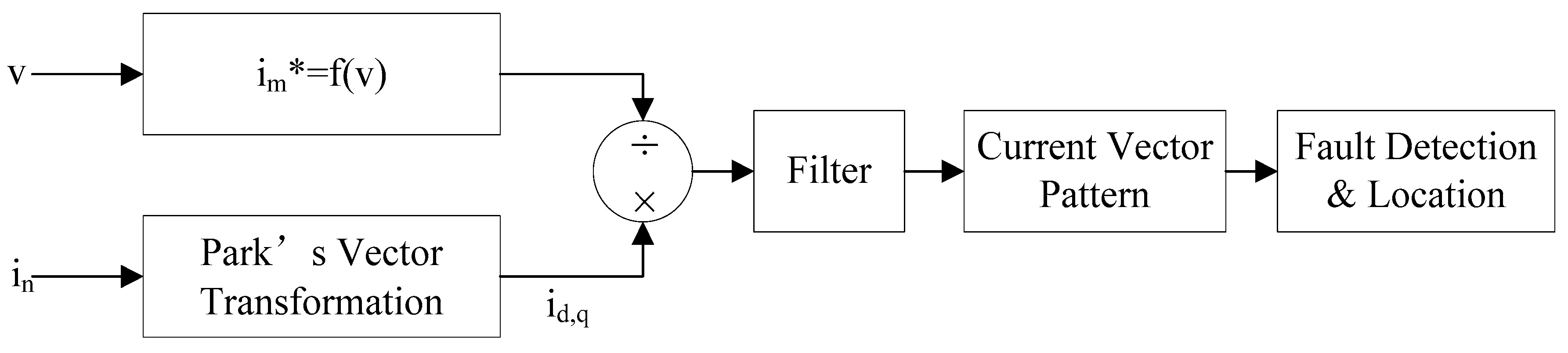
The whole process of WSBMCT fault detection approach is illustrated in
Figure 7. The phase current’s park vectors are firstly normalized, as Equation (24), in order to benchmark against the current magnitude that is determined by wind speeds. The pattern of current’s park vectors are then used for fault diagnosis. Under the step and turbulent wind speeds as shown in
Figure 4b,c, results of using WSBNCT on current vectors to detect T1 switch open-circuit fault are shown in
Figure 8.
Figure 8 shows that recognizable fault patterns are produced by wind speed normalization operation, which essentially eliminates wind speed-induced converter current magnitude fluctuation. However, ripples are still observed in the patterns. These are due to transient current values induced by transient responses of the control system at the moment of wind speed change. Optimizing control parameters can improve the WT system transient response and then smooth the features observed in
Figure 8b. Anyway, WSBNCT is an important premise for intelligent pattern recognition methods that is applied for automatic fault detection. The effectiveness of WSBNCT is achieved by its capability of distinguishing fault features from disturbance of stochastic wind. It helps improve the accuracy of WT converter fault detection under turbulent wind conditions.
4. Experimental Results
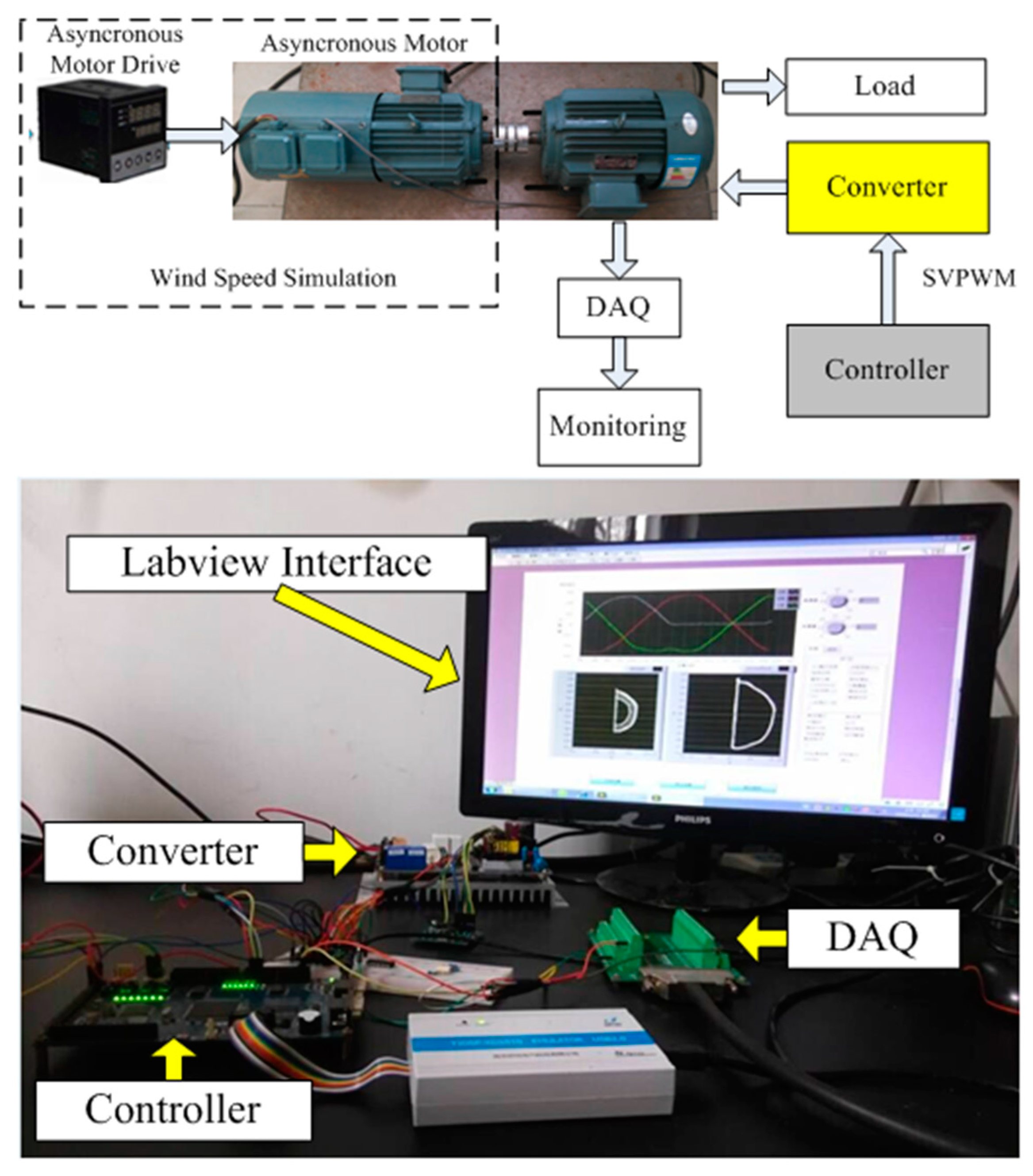
To prove the applicability of WSBNCT approach, an experiment is implemented on the platform illustrated in
Figure 9. A 4 kW asynchronous motor (Jinyi Motor Ltd, Shengzhou, China) and its drive are used and controlled to simulate variable mechanical rotational speed due to stochastic wind speeds. The asynchronous motor is working under V/F control mode which controls the machine’s rotational speed. A 3 kW permanent magnetic synchronous generator (PMSG) (Jinyi Motor, Shengzhou, China) is connected to a converter which is controlled by a F2812 controller board (Yanxu electric technology Co. Ltd., Nanjing, China) under SVPWM control mode. The load used to consume output power is a 100 ohm resistor (Chiyu Electronics Co. Ltd., Kunshan, China). The three phase currents are measured through a Data Acquisition (DAQ) system that is built on a Labview platform based on which the monitoring interface is developed. Experimental device parameters are listed in
Table 2.
A converter switch open-circuit fault is induced by removing the signal of the IGBT in the controller. The WSBNCT method is implemented in the monitoring interface.
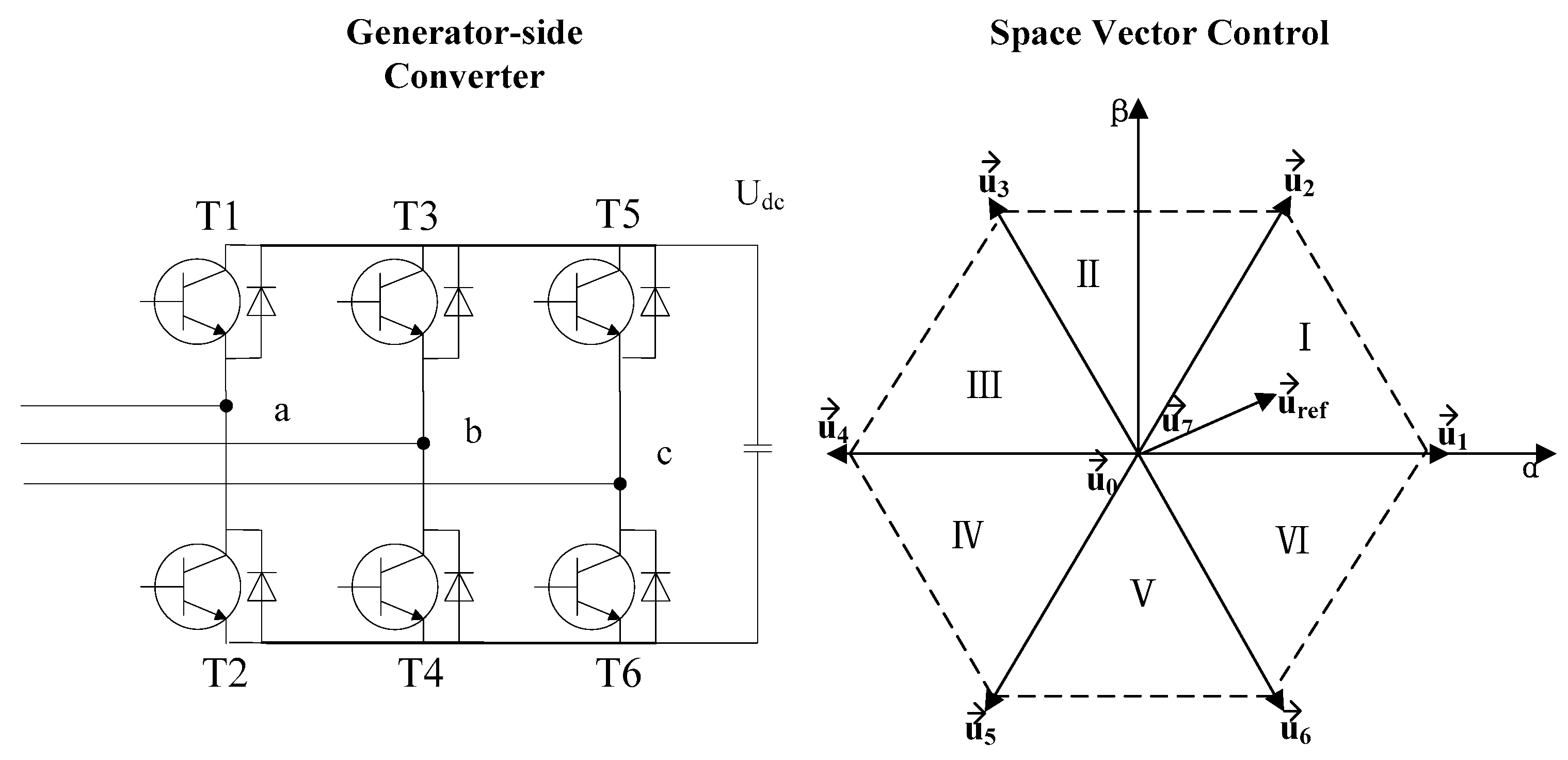
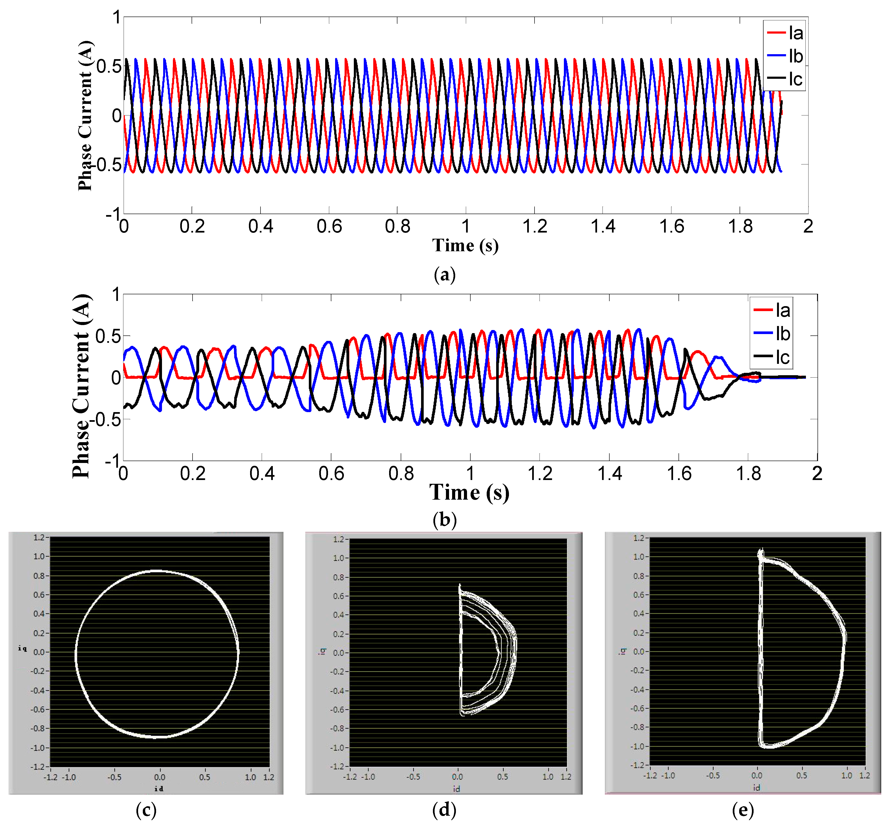
Figure 10 shows the diagnostic result of the WSBNCT under variable rotational speed which is generated corresponding to a step wind situation. Open-circuit faults are introduced for the whole experimental period.
Figure 10a shows the time domain three phase currents of a converter under healthy situation and constant rotational speed, while
Figure 10b shows three time domain phase currents of a converter with T1 switch open circuit and variable rotational speed.
Figure 10c shows that with a constant rotational speed the system with a healthy converter is delivering an ideal circle of
Id-
Iq vector pattern. This is compared to
Figure 10d which shows that the step wind has caused a corresponding rotational speed variation and then the phase currents’ magnitude changes. It shows that without wind speed normalization operation, the fault feature of converters with open-circuited T1 switches generates multiple concentric semicircles that are mainly due to the step wind situation, while with operation of WSBNCT,
Figure 10e shows that wind speed-induced disturbance is eliminated and the current’s park vector pattern converges to a single semicircle. Therefore, the corresponding fault feature is easily identified. For the failure of T2 to T6 switches, the operation is similar and the fault detection is also effective. This proves that WSBNCT method is capable and effective to identify converter open-switch faults for WT applications.
5. Conclusions
A new method named WSBNCT to detect WT converter open-switch faults under stochastic wind conditions is proposed in this paper. The fault detection capability of traditional methods such as the ENCAAV and CVTPR approaches on WT converters are firstly investigated and compared. Stochastic wind speed causing uncertain three phase currents’ periods and unstable values of the current amplitudes are the main reasons that invalidate both methods. According to the operational principle of a WT and the relationship between wind speeds and current magnitudes, WSBNCT method is then proposed and proved to be applicable for WT applications. The comparison of the three methods is summarized in
Table 3. The evaluations of the three methods for WT converter fault diagnosis are summarized as follows:
ENCAAV: its fault diagnosis is based on phase currents which need to be averaged for each complete period. The uncertainty of the period due to stochastic winds make it inapplicable.
CVTPR: its fault diagnosis is based on the current vectors’ pattern in d-q space. The varying current amplitudes due to stochastic wind lead to variable modulus of the current vector and then untracable patterns. It is a more robust method than ENCAAV but it may need further improvement for considering wind speed variation.
WSBNCT: its fault diagnosis is based on the current vectors’ pattern in d-q space like CVTPR. It benchmarks current vectors in the d-q axis against the expected current value obtained from the relationship between wind speeds and currents. It further uses the normalized current vectors to generate pattern in d-q space to detect converter faults.
Experiments involving T1 switch open-circuit fault detection prove the effectiveness and applicability of the WSBNCT approach. The results obtained in this paper confirm the applicability of WSBNCT for WT condition monitoring systems. It should prove a useful method for WT intelligent diagnostic system and will contribute to improve WT availability and the efficiency of wind farm operational management.
Acknowledgments
The authors gratefully acknowledge the financial support from the National Natural Science Foundation of China (Grant No. 51505225), Natural Science Foundation of Jiangsu Province (BK20131350), Jiangsu Top Six Talent Summit Fund (ZBZZ-045), The Fundamental Research Funds for the Central Universities (No. 30915011324), and Returned Overseas Scholars Preferred Funding.
Author Contributions
All the authors contributed to the method proposed, theoretical model development, data analysis and interpretation of the results.
Conflicts of Interest
The authors declare no conflict of interest.
References
- Wu, Z.; Dou, X.; Chu, J.; Hu, M. Operation and control of a direct-driven PMSG-based wind turbine system with an auxiliary parallel grid-side converter. Energies 2013, 6, 3405–3421. [Google Scholar] [CrossRef]
- Spinato, F.; Tavner, P.J.; Van Bussel, G.J.; Koutoulakos, E. Reliability of wind turbine subassemblies. IET Renew. Power Gener. 2009, 3, 387–401. [Google Scholar] [CrossRef]
- Qiao, W.; Lu, D. A survey on wind turbine condition monitoring and fault diagnosis—Part I: Components and subsystems. IEEE Trans. Ind. Electron. 2015, 62, 6536–6545. [Google Scholar] [CrossRef]
- Song, Y.; Wang, B. Survey on reliability of power electronic systems. IEEE Trans. Power Electron. 2013, 28, 591–604. [Google Scholar] [CrossRef]
- Choi, U.M.; Blaabjerg, F.; Lee, K.B. Study and handling methods of power IGBT module failures in power electronic converter systems. IEEE Trans. Power Electron. 2015, 30, 2517–2533. [Google Scholar] [CrossRef]
- Estima, J.O.; Freire, N.M.A.; Cardoso, A.J.M. Recent advances in fault diagnosis by Park’s vector approach. In Proceedings of the IEEE WEMDCD, Paris, France, 11–12 March 2013; pp. 279–288.
- Riera-Guasp, M.; Antonino-Daviu, J.A.; Capolino, G.A. Advances in electrical machine power electronic, and drive condition monitoring and fault detection: State of the art. IEEE Trans. Ind. Electron. 2015, 62, 1746–1759. [Google Scholar] [CrossRef]
- Mendes, A.M.S.; Cardoso, A.J.M.; Saraiva, E.S. Voltage source inverter fault diagnosis in variable speed AC drives, by Park’s vector approach. In Proceedings of the Seventh International Conference on Power Electronics and Variable Speed Drives, London, UK, 21–23 September 1998; Volume 456, pp. 538–543.
- Im, W.S.; Kim, J.M.; Lee, D.C.; Lee, K.B. Diagnosis and fault-tolerant control of three-phase AC–DC PWM converter systems. IEEE Trans. Ind. Appl. 2013, 49, 1539–1547. [Google Scholar] [CrossRef]
- Toubakh, H.; Sayed-Mouchaweh, M. Hybrid dynamic classifier for drift-like fault diagnosis in a class of hybrid dynamic systems: Application to wind turbine converters. Neurocomputing 2016, 171, 1496–1516. [Google Scholar] [CrossRef]
- Shahbazi, M.; Saadate, S.; Poure, P.; Zolghadri, M. Open-circuit switch fault tolerant wind energy conversion system based on six/five-leg reconfigurable converter. Electr. Power Syst. Res. 2016, 137, 104–112. [Google Scholar] [CrossRef] [Green Version]
- Das, P.S.; Kim, K.H. Voltage based online fault detection and faulty switch identification under multiple open switches in grid connected wind power converters. Int. J. Control Autom. 2014, 7, 419–434. [Google Scholar] [CrossRef]
- Freire, N.M.A.; Estima, J.O.; Cardoso, A.J.M. Open-circuit fault diagnosis in PMSG drives for wind turbine applications. IEEE Trans. Ind. Electron. 2013, 60, 3957–3967. [Google Scholar] [CrossRef]
- Ko, Y.J. Fault diagnosis of a three-parallel voltage-source converter for a high-power wind turbine. IET Power Electron. 2012, 3, 1058–1067. [Google Scholar] [CrossRef]
- Slootweg, J.G.; de Haan, S.W.H.; Polinder, H.; Klingl, W.L. General model for representing variable speed wind turbines in power system dynamics simulation. IEEE Trans. Power Syst. 2003, 18, 144–151. [Google Scholar] [CrossRef]
- Qiu, Y.; Sun, J.; Feng, Y. Wind turbine fault simulation. In Proceedings of the 2nd IET Renewable Power Generation Conference, Beijing, China, 9–11 September 2013.
- Sun, T.; Chen, Z.; Blaabjerg, F. Transient stability of DFIG wind turbines at an external short-circuit fault. Wind Energy 2005, 8, 345–360. [Google Scholar] [CrossRef]
- Blaabjerg, F.; Liserre, M.; Ma, K. Power electronics converters for wind turbine systems. IEEE Trans. Ind. Appl. 2012, 48, 708–719. [Google Scholar] [CrossRef]
- Jain, B.; Jain, S.; Nema, R.K. Control strategies of grid interfaced wind energy conversion system: An overview. Renew. Sustain. Energy Rev. 2015, 47, 983–996. [Google Scholar] [CrossRef]
- Chinchilla, M.; Arnaltes, S.; Burgos, J.C. Control of permanent-magnet generators applied to variable-speed wind-energy systems connected to the grid. IEEE Trans. Energy Convers. 2006, 21, 130–135. [Google Scholar] [CrossRef]
© 2016 by the authors; licensee MDPI, Basel, Switzerland. This article is an open access article distributed under the terms and conditions of the Creative Commons Attribution (CC-BY) license (http://creativecommons.org/licenses/by/4.0/).


