Article

A Feed-Forward Control Realizing Fast Response for Three-Branch Interleaved DC-DC Converter in DC Microgrid

1
School of Electric And Electronic Engineering, North China Electric Power University, Beijing 102206, China
2
School of Mathematical And Physical Science, North China Electric Power University, Beijing 102206, China
3
Department of Energy Technology, Aalborg University, Aalborg 9220, Denmark
*
Author to whom correspondence should be addressed.
Energies 2016, 9(7), 529; https://doi.org/10.3390/en9070529
Submission received: 19 May 2016 / Revised: 1 July 2016 / Accepted: 2 July 2016 / Published: 11 July 2016
(This article belongs to the Special Issue Microgrids 2016)

Abstract

:
It is a common practice for storage batteries to be connected to DC microgrid buses through DC-DC converters for voltage support on islanded operation mode. A feed-forward control based dual-loop constant voltage PI control for three-branch interleaved DC-DC converters (TIDC) is proposed for storage batteries in DC microgrids. The working principle of TIDC is analyzed, and the factors influencing the response rate based on the dual-loop constant voltage control for TIDC are discussed, and then the method of feed-forward control for TIDC is studied to improve the response rate for load changing. A prototype of the TIDC is developed and an experimental platform is built. The experiment results show that DC bus voltage sags or swells caused by load changing can be reduced and the time for voltage recovery can be decreased significantly with the proposed feed-forward control.

Graphical Abstract

1. Introduction

With the development of DC distributed generation and energy storage, increasing proportion of DC load and higher requirement for power quality on sensitive loads, DC microgrid will become an important part of power systems in the future. The problems associated with AC microgrids such as synchronization of generators, reactive power and line unbalances, as well as their energy losses when converting to DC, also favor the move to DC microgrids [1,2,3]. Comparing to AC microgrids, it is easier to integrate the renewable energy sources (RES) and storage systems in DC microgrids because of elimination of multiple power conversion stages, especially for some DC sources like PV, fuel cell, battery storage, electric vehicle, super capacitor, etc. [4,5,6,7]. In addition, the total conversion efficiency can be enhanced, and it is easier to reduce charging times for electric vehicles in comparison with AC microgrids [8,9].
The voltage of DC microgrids needs to be controlled by power storages on islanded operation mode so that stable operation of system can be guaranteed. Different capacity and topology of DC microgrids lead to the difference in control strategy for DC-DC converters of power storages. The dual-loop constant voltage control is one of schemes for the stable operation of DC microgrids on islanded operation mode [10,11].
The steady-state deviation of voltage can be eliminated by dual-loop constant voltage control, but when loads are changing, the slow response causes voltage sags or swells, which can be improved by feed-forward control. Using the feed-forward control, a DC-DC converter reported in [12] can rapidly adjust the duty ratio by changing the slope of triangular carrier wave, then fast response can be realized when the input voltage is changing. For two-switch buck-boost DC-DC converters, an input voltage feed-forward control which compensates PWM reference wave to reduce the influence on output voltage induced by input voltage disturbance is proposed by Yao et al. [13]. Aiming at the output DC voltage fluctuation caused by load changing, a digital feed-forward control method for DC-DC converters is proposed by Chae et al. [14], which puts forward that the feed-forward duty ratio is calculated based on charge balance of the output capacitor using the load current, and is combined with the output of the digital PID feedback compensator. A digital control method to enhance the dynamic performance of DC-DC converters, which is used in a plasma display panel, is described in [15], where a simple digital PID compensator with duty ratio feed-forward control is proposed to minimize the output voltage variation while the load current is continuously changing, and the duty ratio feed-forward is calculated using noise-free load current information. This noise-free load current information is predicted by available video data of a plasma display panel. In [16], a feed-forward control for DC-DC converters is achieved. Using equivalent converter electrical model and the desired current reference to calculate the expected operating point, a suitable correction term is added to compensate for the current error. However, the feed-forward controls proposed in [12,13,14,15,16] suit low power applications for single equipment, and cannot be applied in DC microgrids. According to the storage batteries in DC microgrids, authors in [17] have proposed a kind of power feed-forward compensation method. When the feed-forward control is added in the dual-loop constant voltage control, the bus voltage fluctuation caused by load changing can be suppressed.
Three-branch interleaved DC-DC converters (TIDC) can share current among its several phases, and each phase of inductor current is shifted by shifting the phase of switching signals. The ripple of input current, which is the sum of each phase inductor current, becomes smaller than the input current of single-phase DC-DC converters with the same circuit parameters. The hardware-in-the-loop simulation for TIDC is investigated in [18], and the current loop control is used to ensure that each phase current is equally distributed. The experiments have also been done and the results show that this scheme is reliable in [19,20,21]. Higure et al. [22] propose an inductor current control of TIDC using single DC-link current sensor in the high voltage side. This method utilizes the measurement value, which is measured when only one phase switch of upper arms is on-state at the bottom of each carrier. Besides, an association of two ZVS-PWM three-branch current-fed push-pull DC-DC converters is proposed by Albuquerque et al. [23]. Due to the electromagnetic induction principle, the output voltage can be achieved even though the input voltage is lower. In [24], a coordination control strategy for multi TIDC is proposed, and voltage droop control is adopted. Based on this control, every TIDC can adaptively regulate its droop characteristic, and then the globe efficiency optimization in the DC microgrid can be realized.
For the two-way flow of electricity and fast power response, the battery storage has become the key element to integrate distributed generation units into microgrid [25,26]. However, due to the slow response speed of the converter connected to a battery, significant sags or swells of DC bus voltage caused by load changing affects the dynamic characteristics of DC microgrids. In this paper, a feed-forward control based on dual-loop constant voltage PI control for TIDCs is proposed on storage batteries in DC microgrids. In this approach, the dynamic performance of TIDC is improved. When the loads are changing, the voltage transient fluctuation is reduced and the response time is shorter. Finally, the experiment platform is built and the proposed method is verified by physical experiments.

2. Three-Branch Interleaved DC-DC Converter

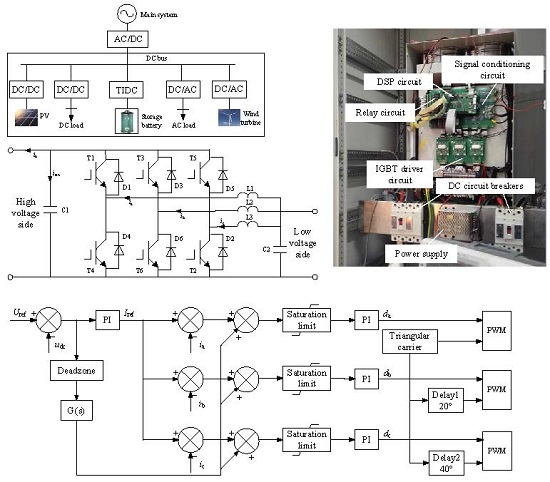
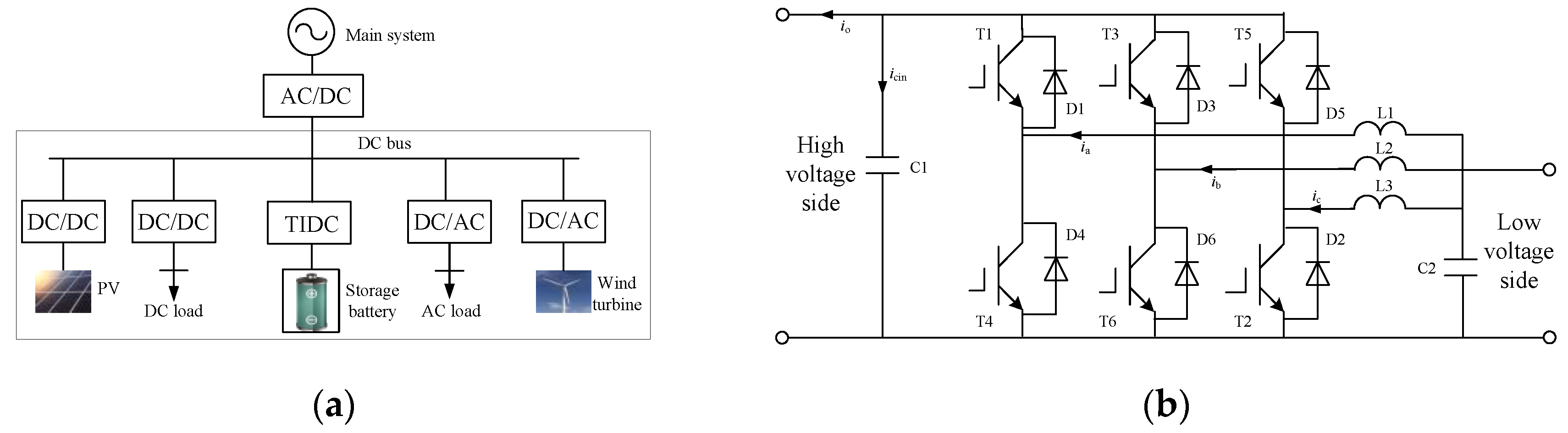
2.1. The Topology of TIDC

A typical structure of DC microgrid is shown in Figure 1a. The storage battery connected to a DC bus through a DC-DC converter regulates voltage and ensures reliability on islanded operation mode. In this paper, the TIDC is used to transfer energy from a storage battery to a DC bus because of the many advantages of such converters [12]. The topology of TIDC is shown in Figure 1b. Either high voltage side or low voltage side can be connected to the battery according to the application need.
The 50 kW prototype of TIDC based on TMS32OF28335 DSP has been designed and manufactured, as shown in Figure 2a. The control circuit consists of the signal conditioning circuit, the relay circuit, the DSP circuit and the IGBT driver circuit. The signal conditioning circuit samples and processes current and voltage signals, and transmits the processed signals to the DSP circuit. The DSP circuit can execute application codes, and then the trigger signals can be transmitted to the IGBT driver circuit to drive IGBTs. The Figure 2b is the experiment waveforms of three-branch currents, which have a difference of 1/3 switching cycle between each other.

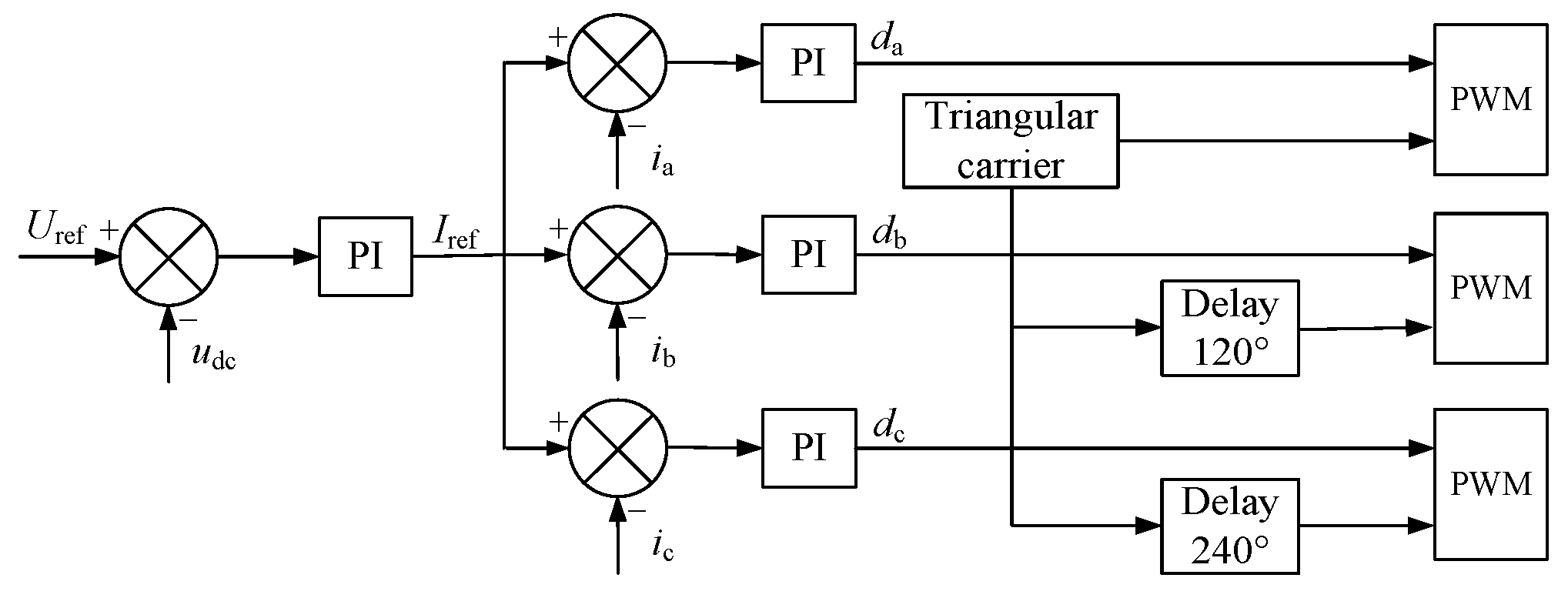
2.2. The Control of TIDC

For prevention of large current and three-branch currents unbalance, the dual-loop constant voltage PI control with an outer voltage loop and an inner current loop is used for the TIDC. The control block diagram is shown in Figure 3, where Uref is the voltage reference of DC bus; udc is the DC bus voltage; Iref is the current reference of the three-branch; ia, ib, and ic are the three-branch currents; and da, db, and dc are duty ratios.
However, slow response speed is the disadvantage of the dual-loop control, and in the real application, the digital filter needs to be used after electrical signals acquisition, which further slows down the response speed. PI parameters include a proportion parameter and an integral parameter, and increasing the proportion parameter can improve the dynamic response without a higher overshoot. However, disturbances of the duty cycle will be bigger under steady-state because of the large proportion parameter which results in larger fluctuating current in the three-branch, as shown in Figure 4. Thus, the feed-forward control based on dual-loop constant voltage PI control is proposed.

3. Analysis of Feed-Forward Control

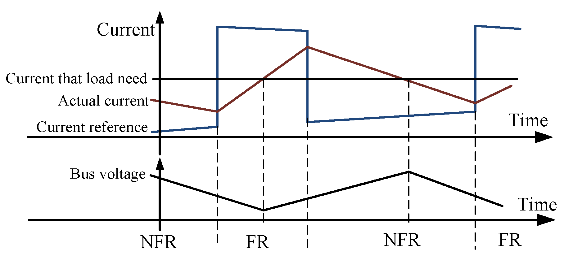
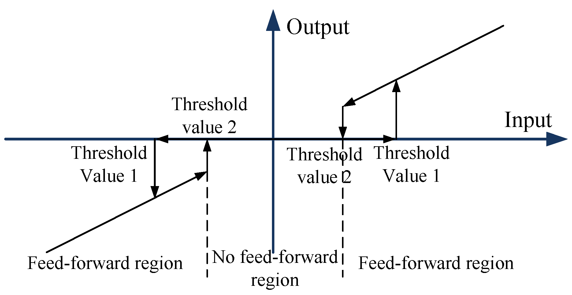
3.1. Presentation of Feed-Forward Control

For any phase in the TIDC, suppose U is the voltage value in the high side, E is the voltage value in the low side, D is the duty ratio of lower bridges, T is the switching period, and the current value is positive when the current flows into the high side from the low side. Both the voltages on the low and high side slightly change in actual operation, so that E and U can be regarded as constant values. Thus the phase-current increment in any arbitrary switching cycle can be obtained:
Δ I = E D ( U E ) ( 1 D ) 2 L T
where ΔI is the phase-current increment in arbitrary switching cycles. At steady-state, the phase-current increment is zero:
Δ I   =   0
Substituting Equation (2) into Equation (1), D can be computed as follows:
D   =   1 E U
It can be found that the duty ratio is determined by the voltages of two sides of the converter at steady-state. When the output power of the converter is required to change, the duty ratio regulating the phase-current will be adjusted. After dynamic process, the duty ratio will go back to the stable point. The changing process of phase-current is shown in Figure 5.
Suppose the battery is connected to the low voltage side to analyze the feed-forward control method. Based on Figure 1b, the following equations can be obtained:
{ i cin ( t ) = C d u dc ( t ) d t i o ( t ) = u dc ( t ) R i cin ( t ) + i o ( t ) = [ i a ( t ) + i b ( t ) + i c ( t ) ] E u dc ( t )
where icin is the current into voltage-stabilizing capacitor; io is the load current; and ia, ib, and ic are three-branch currents. It can be seen that when loads are changing, the energy stored in voltage-stabilizing capacitor need to be used to maintain the power balance as the changing speed of three-branch currents is relatively slow. The voltage on high side can be approximately regarded as the constant value Uref, which is the voltage reference, and assuming that the current reference of inner loop is constant value after load changing. For any phase in the converter based on TMS32OF28335 DSP, PI calculation is completed once during one switching cycle of the corresponding bridge leg, thus the duty ratio of the bridge leg is adjusted. Let Iabc(n) be the current of any phase (since the three-branch currents are balanced) obtained by n times PI calculation after load changing where Iabc(0) is the current of any phase before load changing namely the initial three-branch current value, and Iref be the current reference of inner loop after load changing, so the difference between the current reference and the three-branch currents after load changing is given as:
Δ I abc ( 0 )   =   I ref I abc ( 0 )
Furthermore, the difference between the current reference and the three-branch currents obtained by n times PI calculation after load changing is given as:
Δ I abc ( n )   =   I ref I abc ( n )
Let D0 be the duty ratio before load changing. According to Equation (3), D0 is a constant value that can be expressed as:
D 0   =   1 E U ref
where E is the voltage on the low side, namely the battery voltage. Let kp be the proportion parameter of the inner loop, ki be the integral parameter of the inner loop, T be the switching cycle. In the first switching cycle after the current reference changing into Iref, the difference of the duty ratio compared with D0 can be given as:
Δ D ( 0 )   =   k p Δ I abc ( 0 )   +   k i T Δ I abc ( 0 )
Using Equations (1) and (6), the variable quantity of three-branch currents by the first PI calculation can be given as:
Δ I chg = E [ D 0 + Δ D ( 0 ) ] 2 L T ( U ref E ) [ 1 D 0 Δ D ( 0 ) ] 2 L T = U ref T Δ D ( 0 ) 2 L
Then the difference between the current reference and the three-branch currents after first PI calculation is given in Equation (10):
Δ I abc ( 1 )   =   Δ I abc ( 0 ) Δ I chg ( 0 )   =   Δ I abc ( 0 ) U ref T Δ D ( 0 ) 2 L     =   Δ I abc ( 0 ) U ref k p T Δ I abc ( 0 ) + U ref k i T 2 Δ I abc ( 0 ) 2 L
In the same way, the recursive equations can be written as:
Δ D ( 1 ) = k p Δ I abc ( 1 ) + k i T k = 0 1 Δ I abc ( k ) Δ I abc ( 2 ) = Δ I abc ( 1 ) U ref k p T Δ I abc ( 1 ) + U ref k i T 2 k = 0 1 Δ I abc ( k ) 2 L Δ D ( 2 ) = k p Δ I abc ( 2 ) + k i T k = 0 2 Δ I abc ( k ) Δ I abc ( 3 ) = Δ I abc ( 2 ) U ref k p T Δ I abc ( 2 ) + U ref k i T 2 k = 0 2 Δ I abc ( k ) 2 L Δ D ( n 1 ) = k p Δ I abc ( n 1 ) ) + k i T k = 0 n 1 Δ I abc ( k ) Δ I abc ( n ) = Δ I abc ( n 1 ) U ref k p T Δ I abc ( n 1 ) + U ref k i T 2 k = 0 n 1 Δ I abc ( k ) 2 L
where n ≥ 2. Then, Equations (11) and (12) are given from the above recursive equations:
Δ I abc ( n 1 ) = Δ I abc ( n 2 ) U ref k p T Δ I abc ( n 2 ) + U ref k i T 2 k = 0 n 2 Δ I abc ( k ) 2 L
Δ I abc ( n ) = Δ I abc ( n 1 ) U ref k p T Δ I abc ( n 1 ) + U ref k i T 2 Δ I abc ( n 1 ) 2 L U ref k i T 2 k = 0 n 2 Δ I abc ( k ) 2 L
Substituting Equation (11) into Equation (12), there is:
Δ I abc ( n ) = 4 L U ref k p T U ref k i T 2 2 L Δ I abc ( n 1 ) 2 L U ref k p T 2 L Δ I abc ( n 2 )
Δ I abc ( n 1 ) Δ I abc ( n ) = 2 L U ref k p T U ref k i T 2 2 L [ Δ I abc ( n 2 ) Δ I abc ( n 1 ) ] + U ref k i T 2 2 L Δ I abc ( n 2 )
From Equations (10) and (14), it can be found that in the case of the constant PI parameter, the larger the difference between the current reference and the three-branch currents, the quicker the regulating speed of the three-branch currents. For the dual-loop control, the output signal of the outer voltage loop is the current reference of the inner current loop, so the regulating speed and the range of current reference are limited, which makes the response rate of the three-branch currents slow and result in the variation of bus voltage. Adding the feed-forward into the outer loop, the difference between the current reference and the three-branch currents can be increased when the voltage is fluctuating so that the response speed of the three-branch currents can be improved and the effect of load changing on the bus voltage is depressed. As the feed-forward acts on the current reference, over-current can be avoided due to the saturation limit and three-branch currents balance is guaranteed. The control block diagram is shown in Figure 6, where G(s) is the feed-forward element.
The output value of the feed-forward is increased with the difference value between the voltage reference and the bus voltage. Therefore, the feed-forward element can be set as a proportional control. However, this feed-forward can cause higher three-branch fluctuating currents under steady-state operations. This is the same as the case of the large proportion parameter in PI controller. In order to not start the feed-forward control at steady-state, the dead zone with a hysteresis loop can be added into the feed-forward control, as shown in Figure 7; thus, the feed-forward control starts when the voltage difference is sufficient enough. If the voltage difference reaches the threshold value 1 and enters the feed-forward region (FR), triggering the feed-forward control the larger variations of the current reference will improve the response rate of the three-branch currents and the voltage variations can be inhibited. When the voltage reaches the threshold value 2 and returns to the no feed-forward region (NFR), the feed-forward control stops.

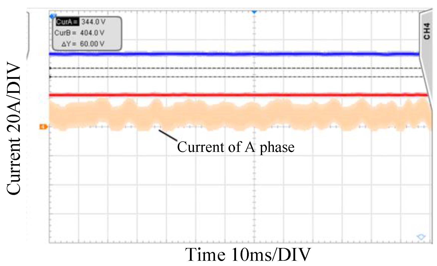
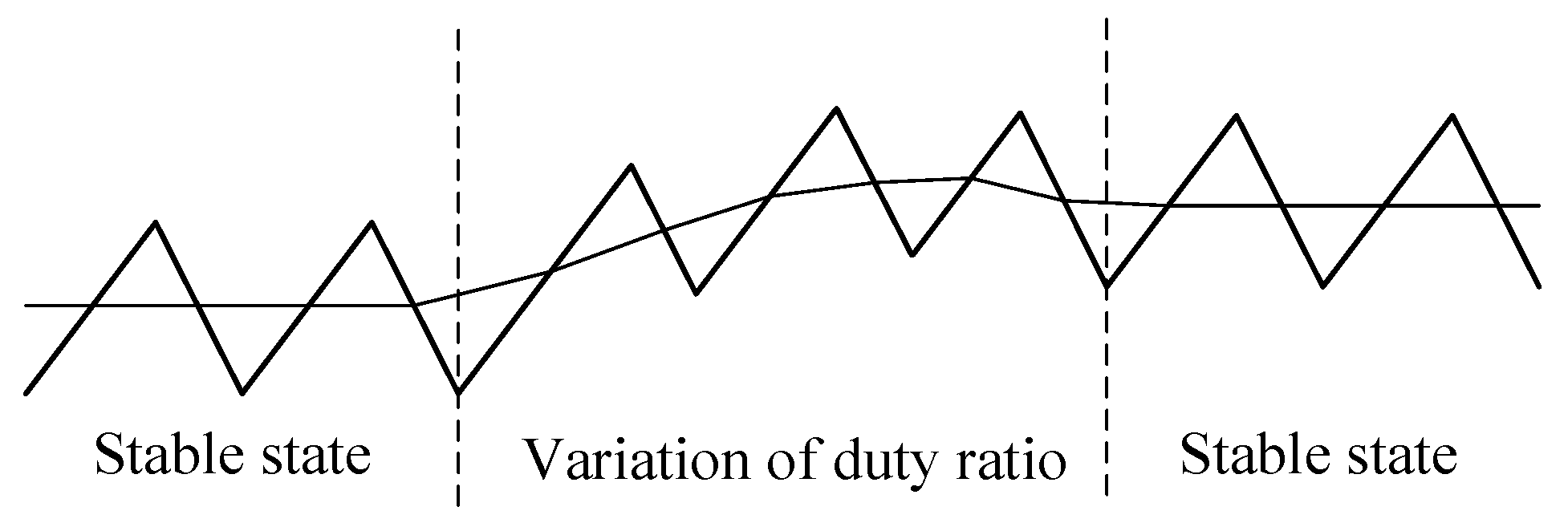
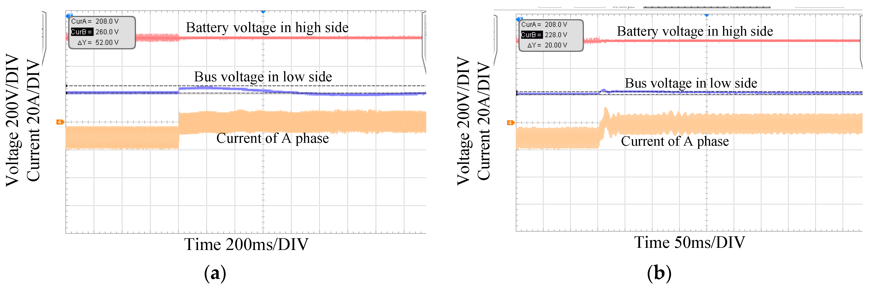
3.2. Defects of Feed-Forward Control and Its Experiment

The proposed method of the feed-forward control can suppress the voltage fluctuation caused by the abrupt change of loads, but some defects exist. For instance, when the load power suddenly increases, the voltage can rapidly return to the NFR from the FR because of the feed-forward control, and the current reference output by the outer loop PI controller has not reached the value that loads need. Under this situation, the three-branch currents will decrease and the bus voltage will go back to the FR to cause the feed-forward control restarting. Since the above process can take place repeatedly, the repeated shocks of three-branch currents will be induced and the voltage can fluctuate between the FR and the NFR, as shown in Figure 8. The process of load-dropping agrees with the above-mentioned ones.
In order to validate the correctness of the analysis method, the experiment platform is built as shown in Figure 9, where the DC bus voltage is set to 500 V, and the battery voltage is 200 V.
Figure 10a shows the bus voltage and the A-phase current waveform when 11 kW loads are put into the DC bus without the feed-forward control, and it can be seen that the value of voltage sags is 84 V. Adding the feed-forward control, when 11 kW loads are put into the DC bus the bus voltage and the A-phase current waveform is shown in Figure 10b, and the value of voltage sags is less than 48 V. The experiment results show that the feed-forward control can reduce voltage sags, but the repeated shocks of three-branch currents and the voltage fluctuation between the FR and the NFR are the main setbacks, therefore, this feed-forward control need further improvement.

4. Improvement of the Feed-Forward Control and Its Experiment

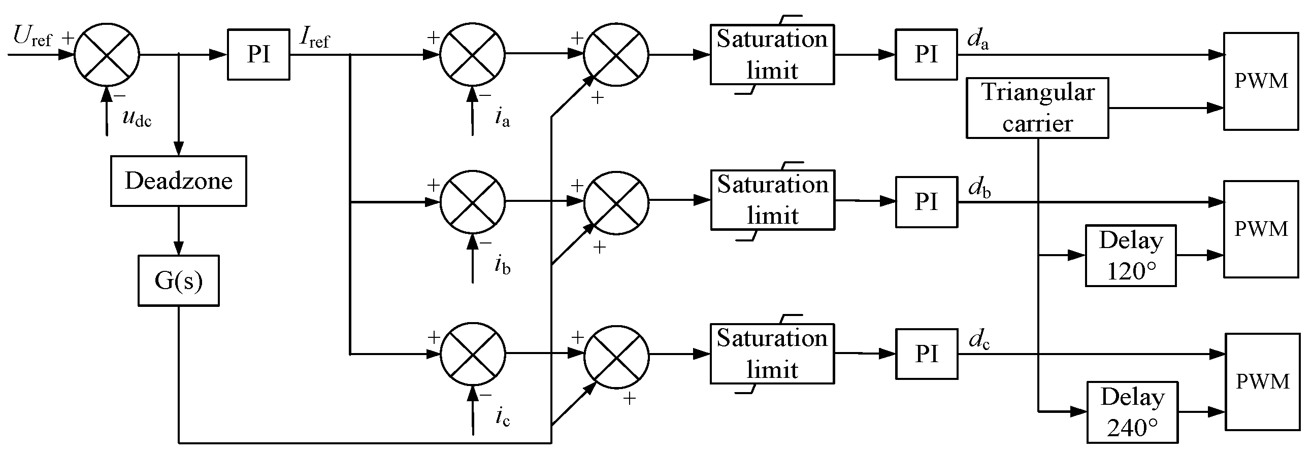
4.1. Improvement of the Feed-Forward Control

The problem is induced by the repeated starting of the feed-forward control and the repeated changing of the current reference. Since the feed-forward element is set as a proportional control, the voltage error cannot be eliminated by the feed-forward control so that the integral calculation in the outer loop PI controller is continuous in spite of the feed-forward control working. Therefore, in order to improve the feed-forward control, after the control’s starting, it should not stop until the current reference output by the outer loop PI controller, mainly due to the integral calculation, has reached the value that loads need.
Let ΔIload be the desired variable quantity of three-branch currents after load changing, Δuload(t) be the steady-state error of bus voltage caused by the proportional component of the PI controller and the feed-forward control, kp be the proportional parameter of the outer loop PI controller, ki be the integral parameter of the outer loop PI control, and K be the proportional parameter of the feed-forward control, thus Equation (15) can be proposed as:
( k p + K ) Δ u load ( t ) + k i 0 t Δ u load ( t ) d t = Δ I load
where the zero-time is the starting instant of the feed-forward control. At the zero-time, the output of the integral part can be approximately regarded as 0, hence:
( k p + K ) Δ u load ( 0 ) = Δ I load
From Equations (15) and (16), the steady-state error of bus voltage caused by the proportional component and the output of the integral part can be given by:
{ Δ u load ( t ) = Δ I load k p + K e k i t k p + K i ki ( t ) = Δ I load ( 1 e k i t k p + K )
where iki(t) is the output of the integral part. In order to maintain the feed-forward control working until the ratio of the current reference output by the integral part to desired variable quantity ΔIload has reached a certain standard, the feed-forward control needs to last a certain time after starting. Let Td be the duration time of the feed-forward control, and η is the ratio of iki(t) to ΔIload when the feed-forward control stops. From Equation (17), Td is:
T d = k p + K k i ln ( 1 η )
Set η as 90%, then:
T d = 2.3 ( k p + K ) k i

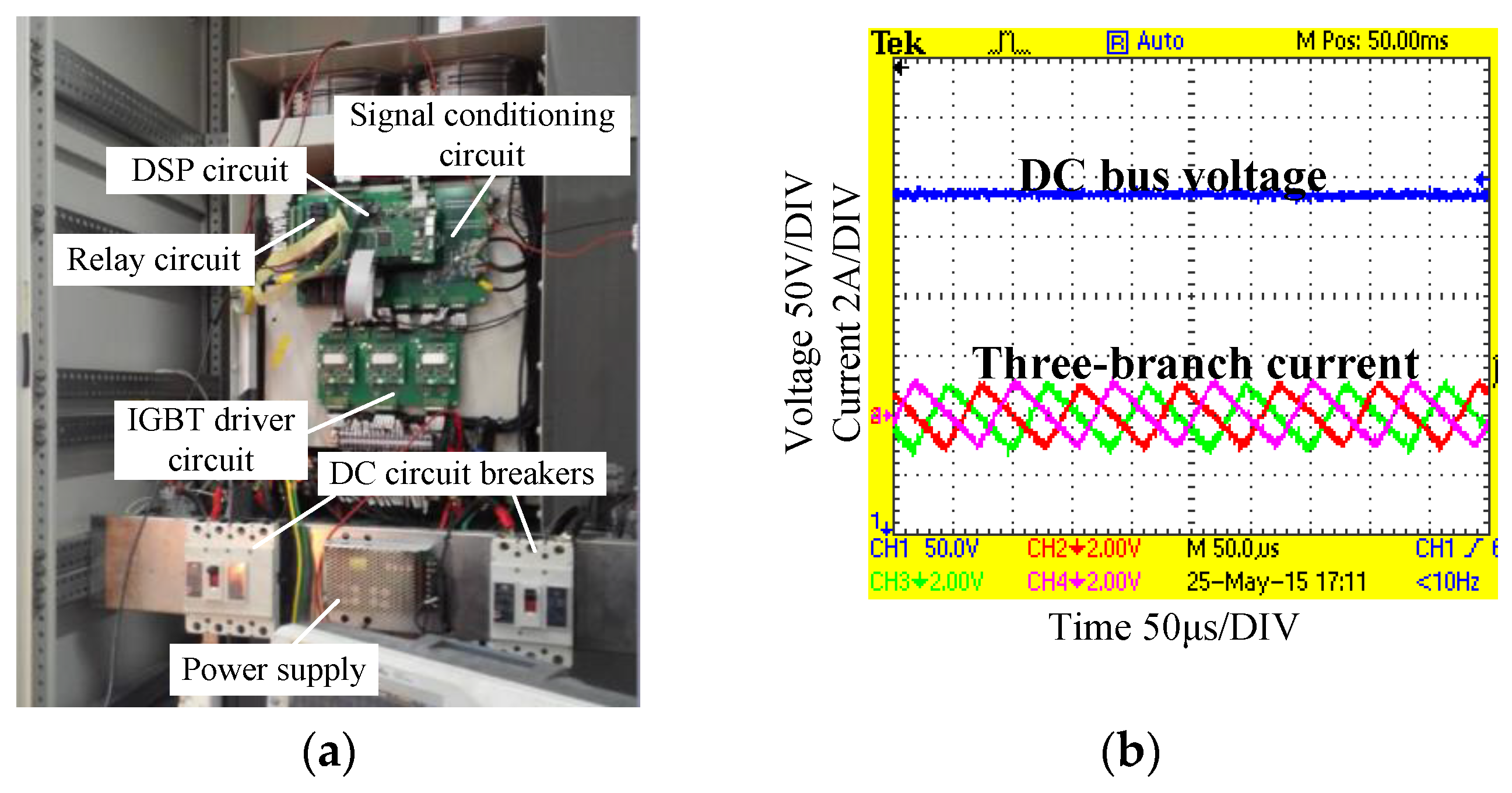
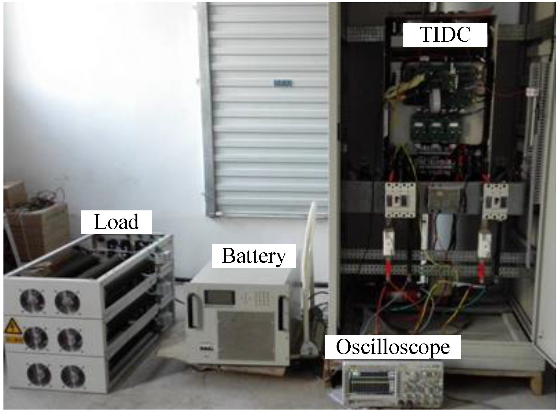
4.2. Experiment of the Improved Feed-Forward Control

The improved feed-forward control is implemented using the experiment platform shown in Figure 9. In this setup, the battery whose voltage is 200 V is connected to the low side of the TIDC, and the voltage reference of the high side is set to 500 V. When 11 kW loads are put into the DC bus without the feed-forward control, the bus voltage and the current of A-phase is shown in Figure 10a and the value of voltage sags is 84 V. With the improved feed-forward control, putting 11 kW loads into DC bus the corresponding waveform is shown in Figure 11. It can be seen that due to this feed-forward control, the value of voltage sags decreases from 84 V to 52 V and the voltage recovery rate is faster without repeated shocks of three-branch currents.
Cutting off 11 kW loads, when there is no feed-forward control, the waveform of bus voltage and the current of A-phase is shown in Figure 12a, and the value of voltage swells reaches 92 V. Using the proposed feed-forward control, the value of voltage swells can be reduced to 44 V, as shown in Figure 12b.
On the other hand, the battery whose voltage is 600 V is connected to the high side of the TIDC, and the DC bus is connected to the low side whose voltage is 210 V. Putting 11 kW loads into the DC bus without the feed-forward control, the corresponding waveform of the voltage and current is shown in Figure 13a. In this figure, it can be seen that the value of voltage sags is up to 40 V. Using the feed-forward control, the waveform with the increase of 11 kW loads is shown in Figure 13b, which shows that the value of voltage sags can be controlled within 20 V.
When 11 kW loads are cut off from the DC bus without the feed-forward control, the value of bus voltage and current of A-phase is shown in Figure 14a and the value of voltage swells is 52 V. With the improved feed-forward control, the value of voltage swells can be basically limited to 20 V and the voltage recovery rate is much faster, as shown in Figure 14b.

5. Conclusions

This paper proposes a feed-forward control based on dual-loop constant voltage PI control for TIDCs, which are employed on storage batteries in DC microgrids. As the feed-forward acts on the current reference, over-current can be avoided due to the saturation limit and three-branch currents balance is guaranteed. In order to not start the feed-forward control at steady-state, the dead zone with a hysteresis loop can be added into the feed-forward control. Every time after starting the feed-forward control, the control should last a certain time to avoid repeated shocks of the three-branch currents and the voltage fluctuation between the FR and the NFR.
The experiment platform is built and the proposed feed-forward control has been tested. The experiment results show that, based on the proposed feed-forward control, DC bus voltage sags or swells caused by load changing can be significantly reduced and the time for voltage recovery has been greatly decreased.

Acknowledgments

This study was supported by the “Intelligent DC Microgrid Living Lab” Sino-Danish Project (2014DFG72620).

Author Contributions

Minxiao Han, Guopeng Zhao and Josep M. Guerrero proposed the idea. Haojie Wang, Minxiao Han and Wenli Yan conceived and designed the experiments. Haojie Wang performed the experiments. Wenli Yan analyzed the data. Haojie Wang wrote the paper. Minxiao Han, Wenli Yan, Guopeng Zhao and Josep M. Guerrero reviewed the manuscript. All authors read and confirmed the final manuscript.

Conflicts of Interest

The authors declare no conflict of interest.

References

  1. Han, M.; Wang, H. DC micro-grid—the important mode in the field of power supply and consumption. J. Electr. Eng. 2015, 10, 1–9. [Google Scholar]
  2. Jian, Z.H.; He, Z.Y.; Jia, J.; Xie, Y. A review of control strategies for DC micro-grid. In Proceedings of the 2013 Fourth International Conference on Intelligent Control and Information (ICICIP), Beijing, China, 9–11 June 2013; pp. 666–671.
  3. Chen, D.; Xu, L. DC microgrid with variable generations and energy storage. In Proceedings of the IET Conference on Renewable Power Generation (RPG 2011), Edinburgh, UK, 6–8 September 2011; pp. 1–6.
  4. Yu, X.; She, X.; Huang, A. Hierarchical power management for DC microgrid in islanding mode and Solid State transformer enabled mode. In Proceedings of the IECON 2013—39th Annual Conference of the IEEE Industrial Electronics Society, Vienna, Austria, 10–13 November 2013; pp. 1656–1661.
  5. Veneri, O.; Capasso, C.; Iannuzzi, D. Experimental evaluation of DC charging architecture for fully-electrified low-power two-wheeler. Appl. Energy 2016, 162, 1428–1438. [Google Scholar] [CrossRef]
  6. Li, S.; Bao, K.; Fu, X.; Zheng, H. Energy management and control of electric vehicle charging stations. Electr. Power Compon. Syst. 2014, 42, 339–347. [Google Scholar] [CrossRef]
  7. Capasso, C.; Veneri, O. Experimental study of a DC charging station for full electric and plug in hybrid vehicles. Appl. Energy 2015, 152, 131–142. [Google Scholar] [CrossRef]
  8. Hõimoja, H.; Rufer, A.; Dziechciaruk, G.; Vezzini, A. An ultrafast EV charging station demonstrator. In Proceedings of the 2012 International Symposium on Power Electronics, Electrical Drives, Automation and Motion (SPEEDAM), Sorrento, Italia, 20–22 June 2012; pp. 1390–1395.
  9. Xiao, J.; Wang, P. Multiple modes control of household DC microgrid with integration of various renewable energy sources. In Proceedings of the IECON 2019th Annual Conference of the IEEE Industrial Electronics Society, Vienna, Austria, 10–13 November 2013; pp. 1773–1778.
  10. Yuan, J.; Gao, F.; Gao, H. Study on multiple hierarchical DC micro-grid based on photovoltaic generation systems. In Proceedings of the 2012 China International Conference on Electricity Distribution (CICED), Shanghai, China, 10–14 September 2012; pp. 1–5.
  11. Kranz, C. Complete digital control method for PWM DCDC boost converter. In Proceedings of the 2003 IEEE 34th Annual Power Electronics Specialist Conference, PESC’03, Acapulco, Mexico, 15–19 June 2003; Volume 2, pp. 951–956.
  12. Zhang, G.; Wu, X.; Zhang, J.; Qian, Z. A Feed-Forward Synchronous-Rectifier Half Bridge DC-DC Converter. Power Electron. 2008, 42, 17–18. [Google Scholar]
  13. Yao, C.; Ruan, X.; Cao, W.; Chen, P. A two-mode control scheme with input voltage feed-forward for the two-switch buck-boost DC–DC converter. IEEE Trans. Power Electron. 2014, 29, 2037–2048. [Google Scholar] [CrossRef]
  14. Chae, S.; Hyun, B.; Kim, W.; Cho, B. Digital load current feed-forward control method for a DC-DC converter. In Proceedings of the Twenty-Third Annual IEEE Applied Power Electronics Conference and Exposition, APEC 2008, Austin, TX, USA, 24–28 February 2008; pp. 498–502.
  15. Chae, S.; Hyun, B.; Agarwal, P.; Kim, W. Digital predictive feed-forward controller for a DC–DC converter in plasma display panel. IEEE Trans. Power Electron. 2008, 23, 627–634. [Google Scholar] [CrossRef]
  16. Pipolo, S.; Bifaretti, S.; Lidozzi, A.; Solero, L. Feed-forward control of a ZVT Full Bridge DC-DC Converter. In Proceedings of the 2015 IEEE 15th International Conference on Environment and Electrical Engineering (EEEIC), Rome, Italia, 10–13 June 2015; pp. 1041–1046.
  17. Lu, Z.; Tang, W.; Zeng, X. Voltage Stability Control of Isolated DC Micro-grid Based on Power Feed Forward. Power Electron. 2015, 49, 32–36. [Google Scholar]
  18. Kang, R.; Kim, K.; Yang, I.; Jeong, K.; Kang, C.; Kim, G. The use of FPGA in HIL Simulation of three phase interleaved DC-DC Converter. In Proceedings of the 2012 OEEE Vehicle Power and Propulsion Conference, Seoul, Korea, 9–12 October 2012; pp. 772–776.
  19. Lee, W.; Han, B.M.; Cha, H. Battery ripple current reduction in a three-phase interleaved dc-dc converter for 5kW battery charger. In Proceedings of the 2011 IEEE Energy Conversion Congress and Exposition (ECCE), Phoenix, AZ, USA, 17–22 September 2011; pp. 3535–3540.
  20. Gavriluta, C.; Citro, C.; Nisak, K.; Segundo, S. A simple approach for fast controller prototyping for a three phase interleaved DC-DC converter. In Proceedings of the 2012 IEEE International Symposium on Industrial Electronics (ISIE), Hangzhou, China, 28–31 May 2012; pp. 2015–2019.
  21. Zwysen, J.; Gelagaev, R.; Driesen, J.; Goossens, S.; Vanvlasselaer, K.; Symens, W.; Schuyten, B. Multi-objective design of a close-coupled inductor for a three-phase interleaved 140kW DC-DC converter. In Proceedings of the IECON 2013–39th Annual Conference of the IEEE Industrial Electronics Society, Vienna, Austria, 10–13 November 2013; pp. 1056–1061.
  22. Higure, H.; Hoshi, N.; Haruna, J. Inductor current control of three-phase interleaved DC-DC converter using single DC-link current sensor. In Proceedings of the 2012 IEEE International Conference on Power Electronics, Drives and Energy Systems (PEDES), Bengaluru, India, 16–19 December 2012; pp. 1–5.
  23. Albuquerque, L.L.O.; Andersen, R.L. Interleaved association of ZVS-PWM three-phase current-fed push-pull DC-DC converters with series output connection. In Proceedings of the 2015 IEEE 13th Brazilian Power Electronics Conference and 1st Southern Power Electronics Conference (COBEP/SPEC), Fortaleza, Brazil, 29 November–2 December 2015; pp. 1–6.
  24. Wang, H.; Han, M.; Josep, M.G.; Luan, W. Optimization Design of DC Micro-grid Stability Controller Based on the Autonomous Decentralized System. Proc. CSEE 2016, 36, 360–367. [Google Scholar]
  25. Zhang, J.; Gao, Z.; Ren, Y.; Du, X.; Yin, X. A economic operation optimization for microgrid with battery storage and load transfer. In Proceedings of the 2014 2nd International Conference on Systems and Informatics (ICSAI), Shanghai, China, 15–17 November 2014; pp. 186–191.
  26. Wang, Y.; Tan, K.T.; So, P.L. Coordinated control of battery energy storage system in a microgrid. In Proceedings of the 2013 IEEE PES Asia-Pacific Power and Energy Engineering Conference (APPEEC), Hong Kong, China, 8–11 December 2013; pp. 1–6.
Figure 1. The Three-Branch Interleaved DC-DC Converter (TIDC) in DC microgrid: (a) a typical structure of DC microgrid; and (b) the topology of the TIDC.
Energies 09 00529 g001
Figure 2. Prototype and experiment waveforms of the TIDC: (a) the 50 kW prototype of the TIDC; and (b) the three-branch currents of the TIDC.
Energies 09 00529 g002
Figure 3. The dual-loop constant voltage PI control for the TIDC.
Energies 09 00529 g003
Figure 4. The three-branch fluctuating current caused by the large proportion parameter.
Energies 09 00529 g004
Figure 5. The changing process of phase current in the TIDC.
Energies 09 00529 g005
Figure 6. The dual-loop constant voltage PI control with feed-forward.
Energies 09 00529 g006
Figure 7. The dead zone with the hysteresis loop.
Energies 09 00529 g007
Figure 8. The repeated shocks of the three-branch currents.
Energies 09 00529 g008
Figure 9. Experiment platform.
Energies 09 00529 g009
Figure 10. Bus voltage and A-phase current waveform when 11 kW loads are put into the DC bus: (a) the bus voltage and A-phase current waveform with the feed-forward control; and (b) the DC bus voltage and A-phase current waveform without the feed-forward control.
Energies 09 00529 g010
Figure 11. Bus voltage and A-phase current waveform when 11 kW loads are put into the DC bus.
Energies 09 00529 g011
Figure 12. Bus voltage and A-phase current waveform when 11 kW loads are cut off: (a) the bus voltage and A-phase current waveform with the improved feed-forward control; and (b) the DC bus voltage and A-phase current waveform without the feed-forward control.
Energies 09 00529 g012
Figure 13. Low bus voltage and A-phase current waveform when 11 kW loads are put into the DC bus: (a) the bus voltage and A-phase current waveform with the improved feed-forward control; and (b) the DC bus the bus voltage and A-phase current waveform without the feed-forward control.
Energies 09 00529 g013
Figure 14. Low bus voltage and A-phase current waveform when 11 kW loads are cut off: (a) the bus voltage and A-phase current waveform with the improved feed-forward control; and (b) the DC bus voltage and A-phase current waveform without the feed-forward control.
Energies 09 00529 g014

