1. Introduction
Wireless power transfer has become a research focus during the last decade, due to its safety and convenience [
1,
2]. Its applications range from mobile phones [
3], and electric vehicles [
4] to electrical equipment in medical and other hazardous fields [
5]. According to the experimental results in [
6,
7], the receiver output voltage varies with the distance, lateral misalignments and angular misalignments between the transmitter and the receiver. Therefore, in order to better power the load, a DC-DC converter is often added to regulate the receiver output voltage [
8,
9]. Due to the uncertainties of power source and load demand in such applications, the DC-DC converters always face the problem of maintaining a smooth output voltage under the circumstances of input voltage perturbations and load disturbances. It has been demonstrated in the literature that traditional linear controllers cannot cope with this problem appropriately. Thus, advanced nonlinear control methods need to be adopted. The sliding mode controller (SMC) is a kind of nonlinear controller which was firstly used in variable structure systems [
10]. The major advantages of SMC are the guaranteed stability and the insensitivity to bounded matched disturbances, including modeling imperfections and/or external disturbances. In the field of power electronics, the switching characterization of DC-DC converters can be well described as variable structure systems [
11,
12]. Thus, it is naturally suitable to use the sliding mode algorithm to control the DC-DC converter under disturbances.
Over the past decade a large amount of literature has presented relevant research works on DC-DC converter controllers using the sliding mode algorithm [
13,
14,
15,
16,
17,
18,
19,
20,
21,
22,
23,
24]. The results have confirmed the strong robustness of the sliding mode control over the traditional linear PI control. In [
13,
14,
15], the authors have presented the practical analog implementation of SMC in the basic DC-DC converters (including buck, boost and buck-boost converters) and had proposed some simple and easy-to-follow design procedures. An improved SMC has been reported in [
16] by eliminating the reaching phase compared with the standard SMC, which enhances the insensibility of the studied boost converter system. Moreover, comparison between PI control and SMC based on the Cuk converter has shown again the latter’s superior output performance [
17]. However, the conventional sliding mode control has two problems that cannot be ignored when applying to DC-DC converter control. The first problem is that in order to achieve an optimized control performance using SMC, the system relative degree [
25] with respect to the sliding variable should be equal to one (the first time derivative of sliding variable explicitly depends on the control
u). For buck power converters, this condition can only be satisfied when the converter inductor current is chosen as the sliding control variable. In this case, the robustness of control under load disturbances cannot be guaranteed. The second problem is related to the so-called chattering effect in sliding mode control, which is difficult to be avoid or attenuated. The chattering effect will results in undesired output voltage ripple of the DC-DC converters.
The two intrinsic constrains of conventional SMC can be mitigated by using high-order sliding mode (HOSM) controllers through transferring the chattering into the high order sliding surface [
26], while preserving the same control robustness. Control of DC-DC converters using super-twisting second order sliding mode has been studied in [
27,
28]. However, among the available literature, systematic and detailed design procedure of HOSM controllers (second-order or higher) applied to DC-DC converters is still an open problem. In this paper, prescribed convergence law (PCL) [
29,
30], which is one of the second-order sliding modes, is chosen and used to control a DC-DC buck converter.
To the best knowledge of the authors, the sliding mode controlled DC-DC buck converter generally needs to measure the capacitor current and the converter output voltage simultaneously [
31,
32]. In DC-DC power converter topologies, the output capacitor current is related directly to the time derivative of converter output voltage. If the output voltage is chosen to be the sliding variable in HOSM, the derivation of the voltage can thus be observed by a differentiator [
33,
34,
35,
36,
37,
38]. Therefore, the capacitor current sensor is no longer needed and can be removed from the control loop, further reduces the hardware cost of the system and provides more advantages compared to traditional PI control. In order to acquire a good output performance of the DC-DC converter, the differentiator should be as accurate as possible. It is inevitable that the input of the differentiator includes some small measurement noise. Thus the differentiator has also to be designed to be robust to the input noise. Super-twisting control, one of the second-order sliding mode algorithms, is suitable for estimating the derivative of the sliding variable.
The main objective of this paper is to propose an innovative controller design to ensure smooth voltage output of a DC-DC buck power converter under the input perturbations and load disturbances. The proposed control design uses a high-order sliding mode controller with a robust differentiator (HOSM + STD), and is based only on the measurement of converter output voltage. This paper is a major extension of the work presented in [
39]. The main contributions of this paper can be summarized as follows:
A robust HOSM controller based on PCL is designed for DC-DC buck converters, the corresponding systematic and detailed design procedure is presented in detail through theoretical analysis and simulation studies.
By adding a super-twisting differentiator (STD) into the controller design, the current sensor is no longer needed for the converter control. The proposed HOSM + STD controller only uses the measurement of output voltage as control input. Thus the control system is simplified and the robustness of HOSM can also be preserved.
The paper is organized as follows:
Section 2 and
Section 3 introduce the super-twisting differentiator and high order sliding mode controller for buck converters, respectively. Numerical simulations under various conditions have been presented in
Section 4. The experimental results in
Section 5 demonstrate the validity and the effectiveness of the proposed HOSM and HOSM + STD controllers. Finally, conclusions are given in
Section 6.
3. Sliding Mode Controller Design
Consider a general linear system with relative degree two in state-space form [
30]:
, with the sliding variable:
where
x = [
x1,
x2]
T is the state variable matrix,
a,
b, σ are smooth unknown functions. Calculation of the second derivative of σ and yields:
where
h(
t,
x) and
g(
t,
x) are unknown functions. Assume that:
holds globally for
Km,
KM,
H > 0. Then Equations (15) and (16) imply the differential inclusion:
Thus the problem becomes to find a robust control law:
such that σ and
could approach to zero exponentially or in finite time.
3.1. Traditional Sliding Mode Control
The sliding mode control design process can be divided into two parts: the first part is to define a switching manifold
S(x) which describe the desirable dynamic properties. The second part is to then define a discontinuous control law
u:
such that:
In [
13],
is chosen as the sliding surface, and the corresponding control law for DC-DC buck converter was designed as:
The positive parameter
k recommended by [
13] is:
by taking into account the maximum existence region based on the existence condition [
13]. Wherein
R is the load resistance and
C is the capacitance of the buck converter.
The sliding mode control process can be distinguished into sliding mode phase and reaching phase. During the sliding mode phase, there exists:
It is clear that
x1 and
x2 approach to zero exponentially under traditional sliding mode control. Moreover, the proportional-derivative (PD) type feedback in traditional sliding mode control Equation (23) will cause a nonzero steady state error in the DC-DC buck converter output voltage [
41]. Indeed, the nonzero steady state error can be attenuated by adding an integral term and a double integral term of all other existing state variables in sliding mode surface [
42]. However, this will increase the number of controller parameters and finally increase the design complexity. The drawback of nonzero steady state error is significantly improved by the following proposed controllers without adding the number of design parameters.
3.2. Second Order Sliding Mode Control
As described previously, a DC-DC buck converter is a system with relative degree of two. Thus it might be more suitable to use the second order sliding mode controller to improve the control accuracy and convergence time. The Prescribed Convergence Law (PCL), which is a type of second order sliding mode control, is defined as [
29,
30]:
where α > 0, β > 0.
It has been demonstrated in [
30] that the controller can guarantee the establishment and maintenance of a second-order sliding mode
for the sliding variable dynamics Equation (17) in finite time, if the following precondition could be satisfied:
For the DC-DC buck converter application, the control signal for the power switch belongs to {0, 1}. When
u = 1, the power switch is on, and when
u = 0, the power switch is off. Therefore, be similar to Equations (21), (25) and (26) can be reformulated as:
According to Equations (3) and (14)–(16), the
Km and
H can be formulated as:
Thus, in the proposed controller design, the only design parameter is β, which must satisfy Equation (28). It has to be noted that, Equation (28) ensures the finite time convergence of with the second order sliding mode control PCL. Thus the bigger the value of β, the faster the convergence.
As a result, the proposed High-Order Sliding Mode (HOSM) controller with Super-Twisting Differentiator (STD) for DC-DC buck converter can thus be expressed as:
where
is the estimation of
based on STD in Equation (8).
4. Simulation Results
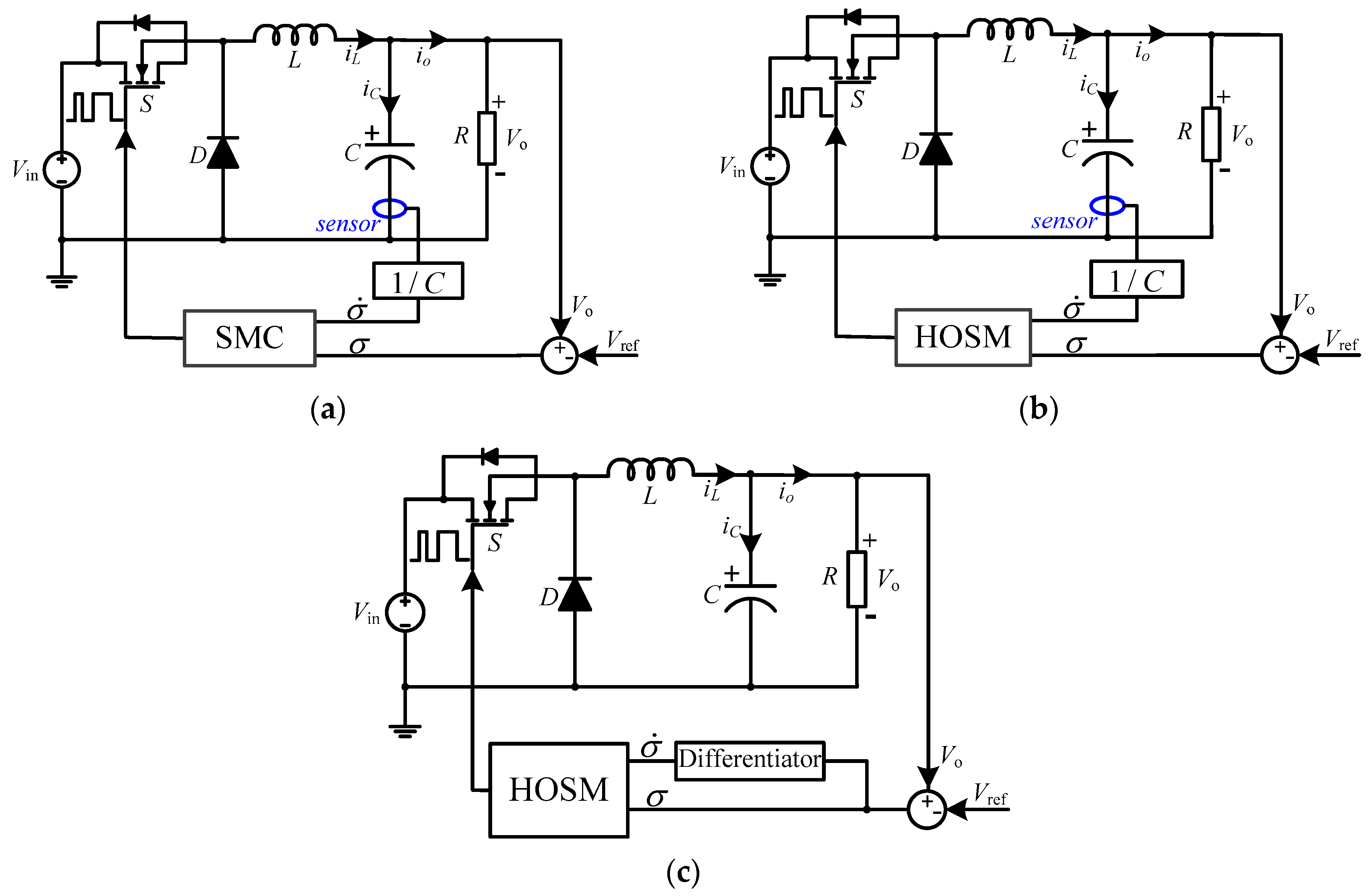
To verify the effectiveness and robustness of the proposed innovative control method in this paper, three simulation models (SMC, HOSM, HOSM + STD) were established in Matlab/Simulink based on diagrams shown in
Figure 1. For the simulation diagrams of
Figure 1a,b, both output voltage and capacitor current are measured and treated as the inputs of the controller for the buck converter. While for simulation diagram of
Figure 1c, the error between the measured output voltage and the reference voltage is treated as the input of the differentiator and the sliding mode controller. There is no capacitor current measurement in
Figure 1c.
The design index and circuit parameter are listed in
Table 1. Substitute the data into Equations (11), (12), (22) and (28)–(30), both the differentiator and the controller can then be designed. The calculated parameter of λ
0, λ
1,
k and β are summarized in
Table 2.
For each presented control diagram, numerical simulation results (carried out using the Euler solver with a time step 10 μs) under steady state, input voltage perturbations and output load disturbances have been compared and presented hereafter.
4.1. Controller Performance with Different Design Parameters
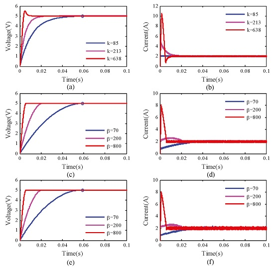
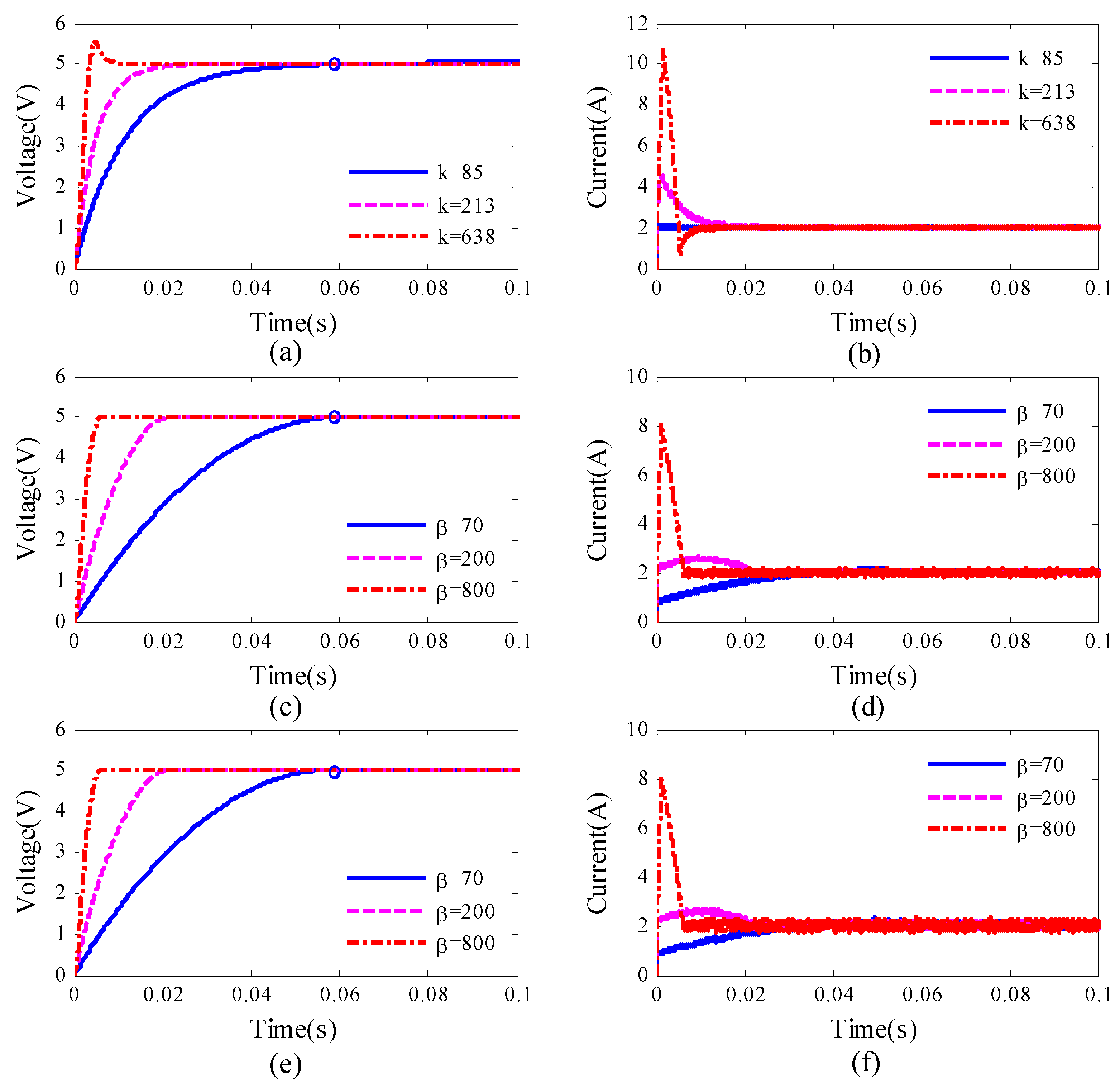
Under the nominal working condition, the input voltage is set to 15 V, and the load resistance is set to 2.5 Ω. The output voltage and the corresponding inductor current curves of a buck converter under different controllers with various controller parameters are pictured in
Figure 2.
It can be seen clearly from the figure that, a bigger value of controller design parameters
k and β can lead to a faster response of the output voltage, but if the value of
k or β becomes too large, voltage overshoot might occur for both output voltage and inductor current, as shown in
Figure 2a,b. The current overshoot phenomenon is however inevitable for HOSM, as presented in
Figure 2c,d. Therefore, when tuning the value of
k and β, the output voltage convergence speed and the possible current overshoot should both be considered and a balance need to be found. The peak inductor current can be calculated as follows:
Take
Figure 2b as an example of SMC, suppose that the Equation (23) is established sooner after the start up, there exists:
The inductor current can be formulated as:
If the minimum inductor current overshoot is expected, the biggest
k can be set to 1/(RC), which coincides with the results in Equation (22). If
k equals to 1/(RC), we would have:
This calculated values (2 A) is identical to the simulation result plotted with blue solid line in
Figure 2b, which demonstrate the effectiveness of Equation (33). Similar to the analysis of SMC, the peak inductor current of the buck converter controlled by HOSM can also be estimated. Take
Figure 2d as an example, without loss of generality, suppose that there exists:
according to Equation (32), we can have:
In order to test the effectiveness of Equation (34), we take red dot-dash line in
Figure 2d as an example: substitutes β = 800 into Equation (34), one obtains:
This calculation result is coincide with the simulation results in
Figure 2d. Then based on Equation (34), the critical value of β about whether the current overshoot phenomenon occurs can be calculated as:
It should be kept in mind that Equations (33) and (34) can only provide an estimation of peak inductor current during the start-up process.
From
Figure 2c,e, it can be seen that the HOSM + STD has similar convergence speed (see the small blue circle in
Figure 2) as that of HOSM. From
Figure 2d,f, it can be seen that HOSM + STD may cause a slightly bigger ripple in the inductor current. Otherwise, the STD cooperates with HOSM very well.
It should be noted that, in this paper, the
k is chosen according to Equation (22), while in order to let the rising time of SMC and HOSM be equal, the value of
β is selected properly as in
Table 2. Theoretically, the β can be chosen up to 190 with the consideration of the inductor current overshoot avoidance. It implies also that the HOSM can achieve faster convergence than SMC under the same constrains of the current overshoot avoidance.
4.2. Disturbance in Input Voltage
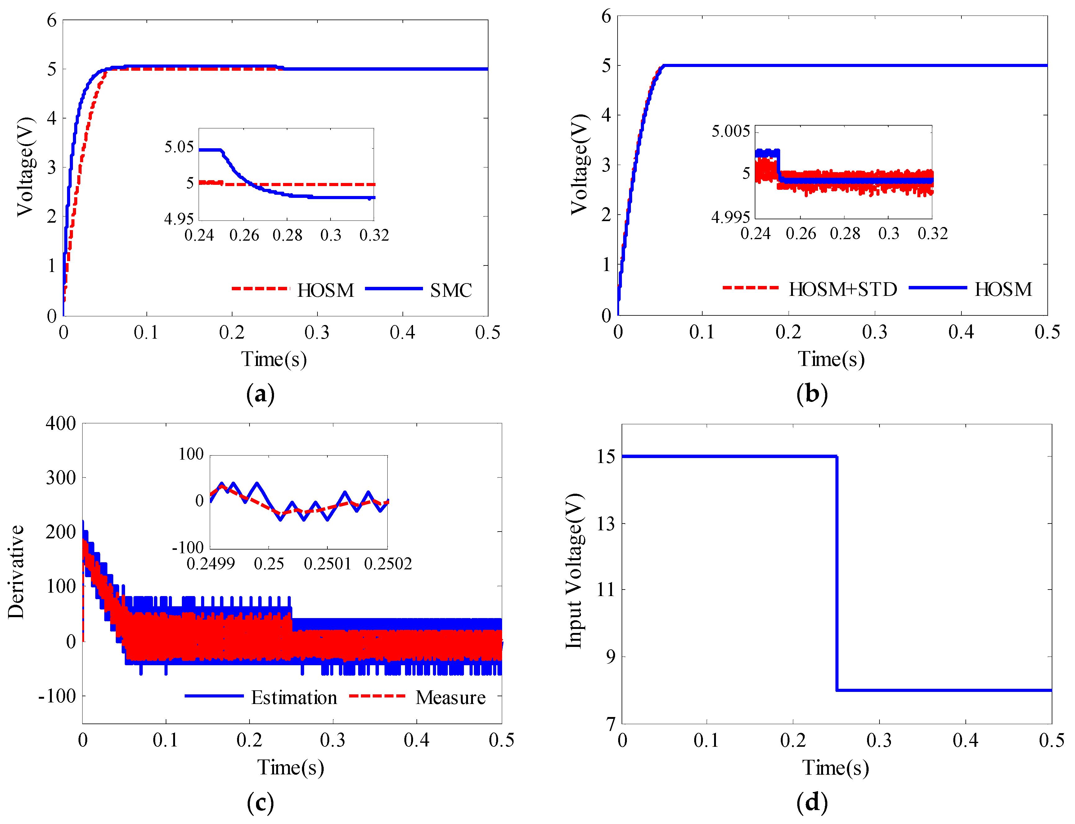
In order to test the robustness of the proposed controller against the input voltage disturbance, a step change from 15 to 8 V at 0.25 s is applied to the buck converter input voltage. The simulation results are shown in
Figure 3. Before to start the discussion about robustness of the controller, the steady state performance is analyzed at first, as given in
Table 3. It can be seen that SMC and HOSM has the same rising time 57.5 ms, but HOSM can achieve smaller steady state error than SMC. In
Figure 3, it is shown that the proposed Super-Twisting Differentiator (STD) works well since the start-up and the steady state performance of HOSM + STD is similar to that of HOSM, except a slightly bigger output voltage ripple. The additional output voltage ripple is mainly caused by the fact that the estimated derivation is less smooth than the measured derivative, as shown in
Figure 3c.
From
Figure 3, it can be concluded that, all these three controllers show robustness to the input voltage disturbance. The detailed analysis results are presented in
Table 4. The controlled output voltage drop of SMC is 67.9 mV, and needs 73.8 ms recovery time. While the voltage drop of HOSM controllers is 3.2 mV and needs about 1.3 ms recovery time. The combination of HOSM + STD controller also shows strong robustness to the input voltage disturbance, the voltage drop of HOSM + STD is 1.4 mV and needs about 0.1 ms recovery time.
4.3. Disturbance in Output Load Resistance
In order to test the robustness of the proposed controller for the buck converter under load disturbance, the load is doubled at 0.25 s. The corresponding simulation results are compared and pictured in
Figure 4.
It can be concluded that all these three controllers show strong robustness to the load disturbance. The more detailed analysis results are listed in
Table 5, where it can be seen that the transient voltage drop is similar for all controllers (about 25 mV), which is mainly determined by the buck converter circuits (inductor, capacitor) and load current. The recovery time of SMC is about 30.6 ms, HOSM needs 5.1 ms, and that of HOSM + STD is about 2.1 ms. The results have demonstrate that the proposed HOSM + STD shows strong robustness to the load disturbance, according to
Figure 4b. It can also be seen from
Figure 4b that, the proposed HOSM + STD has the similar dynamic performance as single HOSM controllers with additional current input.
5. Experimental Results
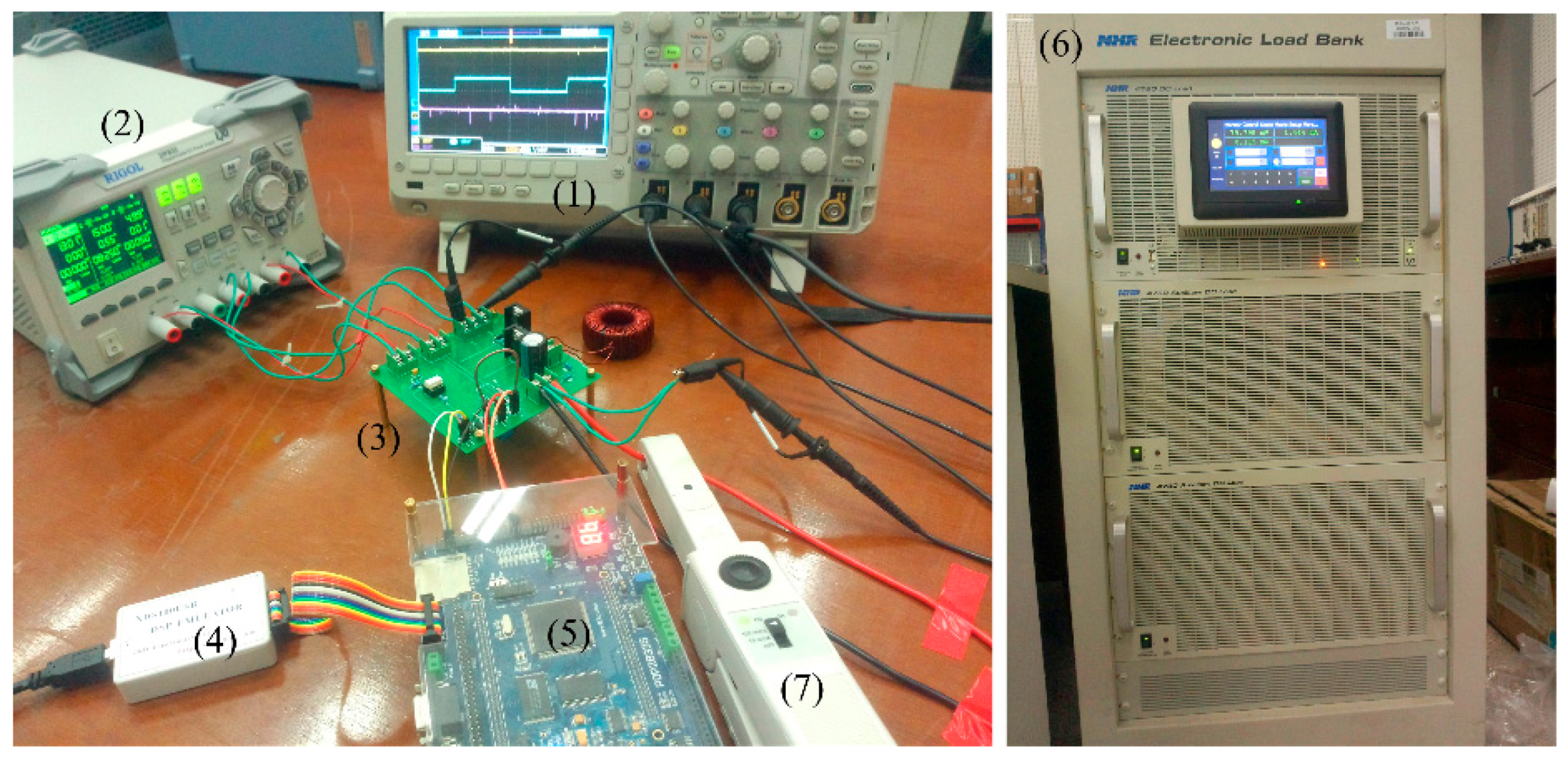
Furthermore, in order to valid experimentally the effectiveness of the proposed HOSM and HOSM + STD controllers, an experimental setup including a prototype DC-DC buck converter and a control board based on 32 bit-150 MHz TMS320F28335 (Digital Signal Processor from Texas Instruments, Dallas, TX, USA) had been established, as shown in
Figure 5. The experimental circuit parameters are the same as shown in
Table 1. In order to better evaluate the presented control method, the classical proportional-integral (PI) controller has been comparatively studied. The controller parameters of SMC, HOSM and HOSM + STD are chosen as λ
0 = 2 × 10
6, λ
1 = 2 × 10
3,
k = 85, β = 300 in the following experiments. The PI controller parameters are tuned by combing bode diagram and cut-and-trial method, and finally set as
Kp = 0.7,
Ki = 84.
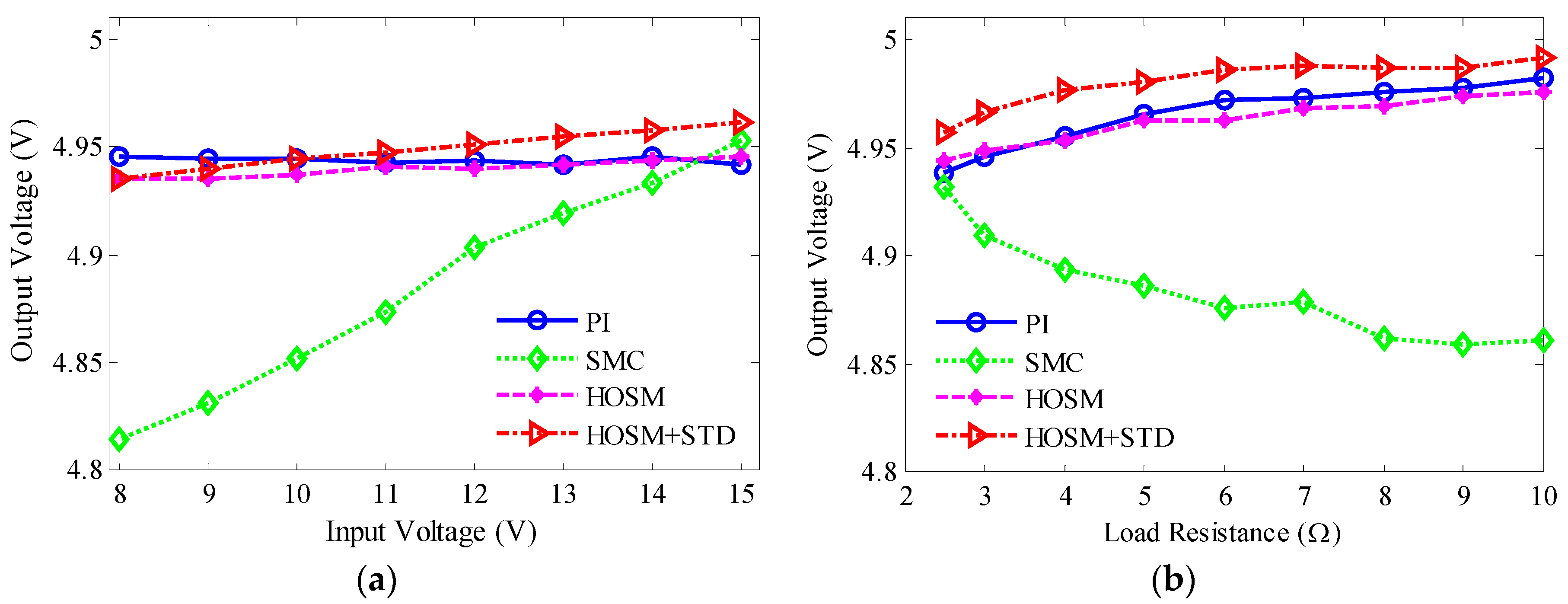
Figure 6a,b shows the steady state performance of these four controllers (PI, SMC, HOSM and HOSM + STD). From
Figure 6a, it can be concluded that PI, HOSM and HOSM + STD can achieve less steady state error and better voltage regulation than SMC. In particular, the HOSM + STD controller has the similar performance with HOSM, especially with low input voltage. Note that the experimental steady state error is larger than that of simulation results in
Table 3. There could be many reasons for this observed difference, such as the measure and sampling imperfections, the discretization of the controller and the differentiator. From
Figure 6b, it can be concluded that PI and HOSM have smaller steady state error and better load regulation than SMC during the whole load range. Particularly, the HOSM + STD controller still has the similar performance with HOSM.
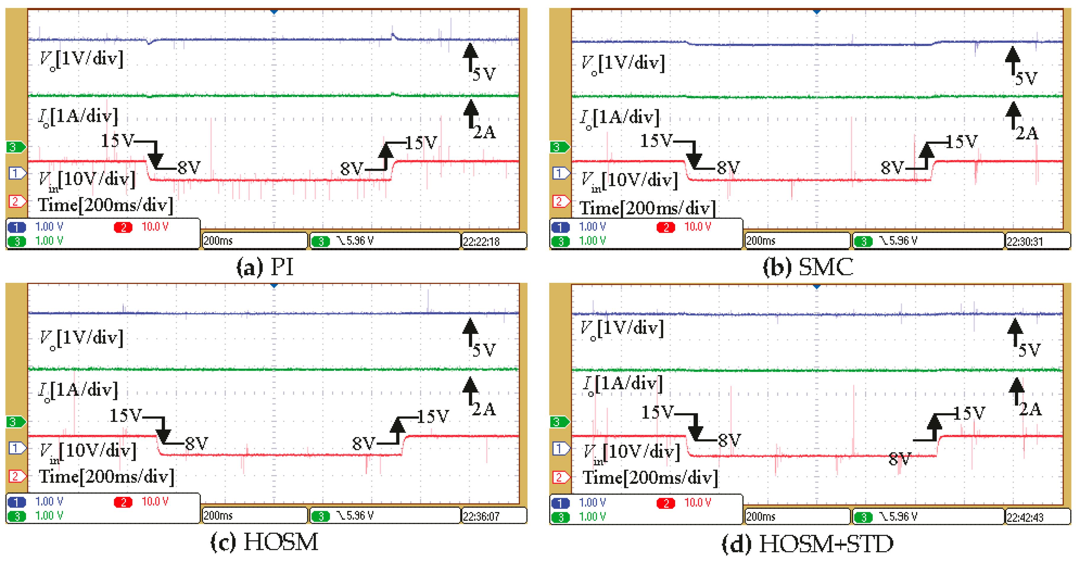
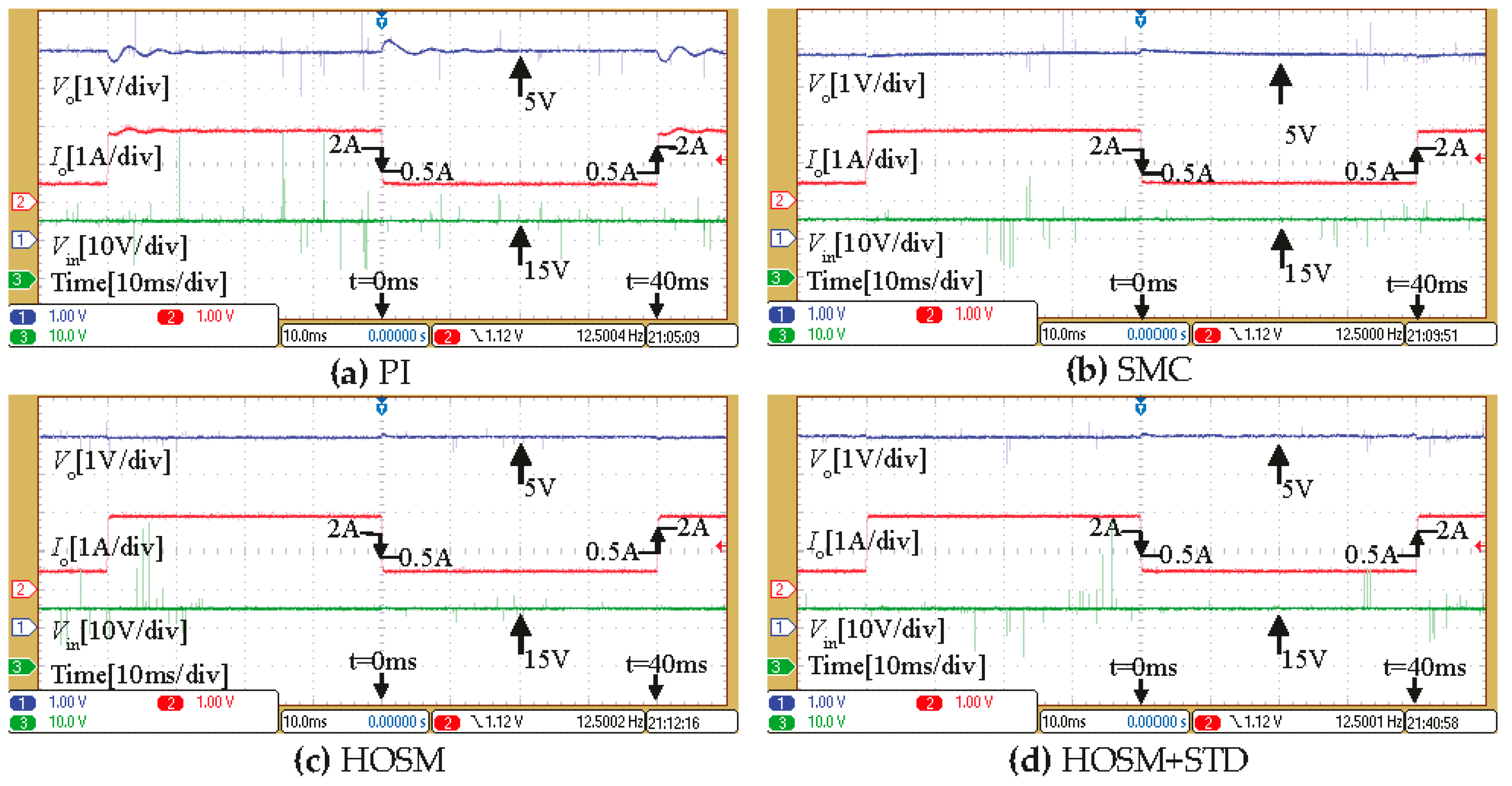
In the second experimental test, to valid the robustness to the input voltage perturbations, step changes from 15 to 8 V and back to 15 V are applied to the buck converter with a constant 2.5 Ω load. The experimental results are shown in
Figure 7.
As it can be seen from the figure, all four controllers show robustness to the input voltage perturbations. However, the voltage drop observed in SMC is bigger (about 120 mV), when compared with PI, HOSM and HOSM + STD. It is easy to indicate that the HOSM and HOSM + STD have better transient performance than PI controller, the overshoot and undershoot is almost negligible. The comparative analysis results between PI and HOSM + STD are shown in
Table 6.
Finally, in order to test the robustness of the proposed controller against the output load resistance disturbances, the load resistance is changed from 10 to 2.5 Ω and returns to 10 Ω. The load disturbance is realized by using an electronic load in
Figure 5. The corresponding experimental results are presented in
Figure 8.
Similarly to the simulation results in
Figure 4a,b, all four controllers show robustness to the load resistance disturbances. However, the PI controller has limited transient performance, such as the longer recovery time and larger overshoot/undershoot. The comparative analysis results between PI and HOSM + STD are shown in
Table 6.


