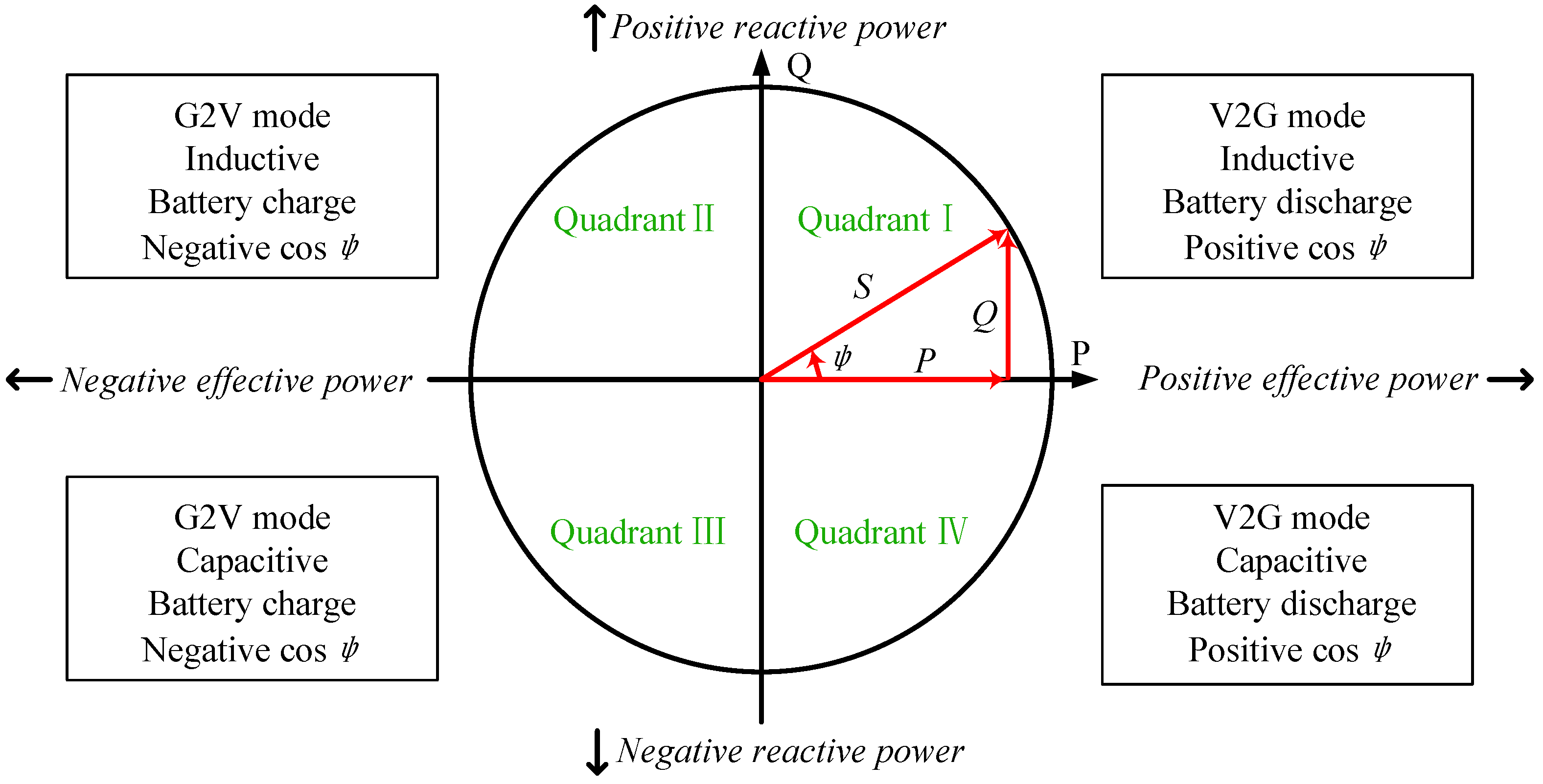
Article

An Integrated Multifunctional Bidirectional AC/DC and DC/DC Converter for Electric Vehicles Applications

National Engineering Laboratory for Electric Vehicles, Beijing Institute of Technology, Beijing 100081, China
*
Author to whom correspondence should be addressed.
Energies 2016, 9(7), 493; https://doi.org/10.3390/en9070493
Submission received: 1 March 2016 / Revised: 14 June 2016 / Accepted: 22 June 2016 / Published: 28 June 2016
(This article belongs to the Special Issue Advanced Electrification for Transportation and Built Environment)

Abstract

:
This paper presents an on-board vehicular battery charger that integrates bidirectional AC/DC converter and DC/DC converter to achieve high power density for application in electric vehicles (EVs). The integrated charger is able to transfer electrical energy between the battery pack and the electric traction system and to function as an AC/DC battery charger. The integrated charger topology is presented and the design of passive components is discussed. The control schemes are developed for motor drive system and battery-charging system with a power pulsation reduction circuit. Simulation results in MATLAB/Simulink and experiments on a 30-kW motor drive and 3.3-kW AC/DC charging prototype validate the performance of the proposed technology. In addition, power losses, efficiency comparison and thermal stress for the integrated charger are illustrated. The results of the analyses show the validity of the advanced integrated charger for electric vehicles.

Graphical Abstract

1. Introduction

As the demand for renewable energy increases, alternative and sustainable transportation methods become more attractive in comparison to conventional transportation. Electric vehicles (EVs) are efficient solution which draws interest of government, manufacturers and researchers [1,2,3,4]. However, the lack of a convenient charging options prevents widespread use of EVs. In order to overcome this issue and make EVs more competitive, an efficient and reliable, high power density, low cost, small size and lightweight on-board charger for EVs becomes a valuable topic [5].
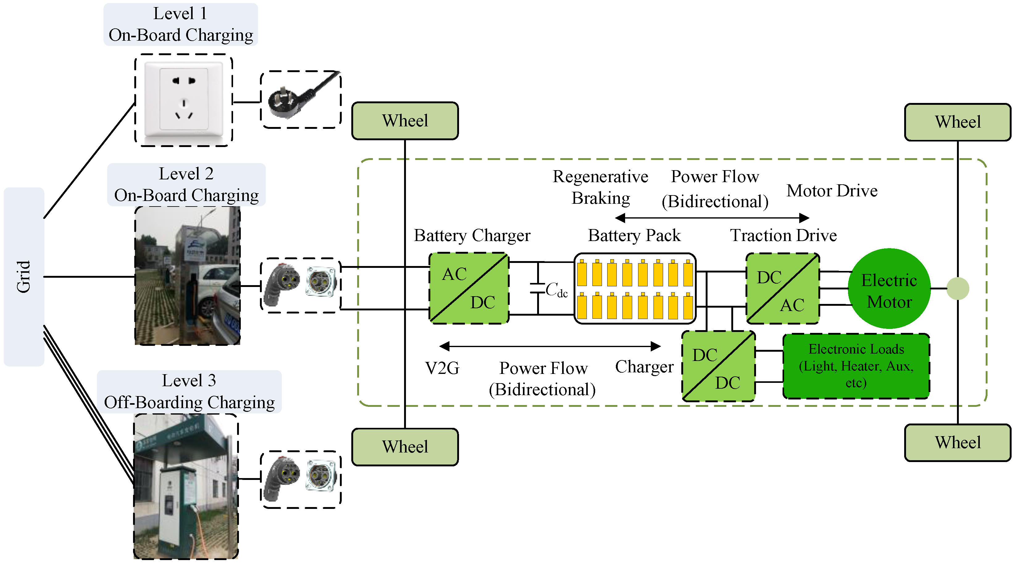
EV charging power levels defined by society of automotive engineers (SAE) are summarized and classified in Figure 1: Level 1 charging is slow charging; Level 2 charging is assumed primary charging level; and Level 3 is intended for off-board charging infrastructure providing quick charging. In terms of application, an off-board charger can be designed for high charging rates and is less constrained by size and weight. On-board battery chargers can reduce user range anxiety by allowing for battery packs to be charged from any available power outlet [6]. However, on-board charging increases system volume and weight. A compact, high power density charger is needed to maintain vehicle operation efficiency. Galvanic isolation from the utility grid is a favorable option in the charger circuits because of safety reasons, but isolated on-board chargers are usually avoided due to their cost impact on the system. With a dedicated socket-outlet, earth current monitoring is an optional function as mentioned in the standard [7]. The electrical continuity of the earth conductor should be permanently monitored by the charger, and in the case of loss of electrical continuity of the earth conductor, the charger shall be switched off. In addition, if the traction battery is bonded to the vehicle chassis, the charging system shall provide a galvanic isolation between the mains and the battery. For the chargers, they are classified into conductive charging and inductive charging [8]. The inductive charging can be implemented wireless charging, which has lower efficiency.
An on-board battery charger is an inevitable part of an EV powertrain [
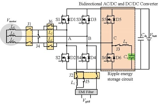
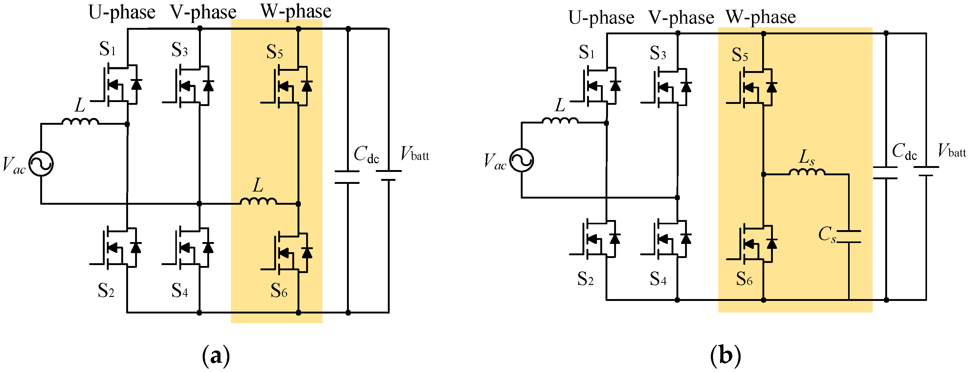
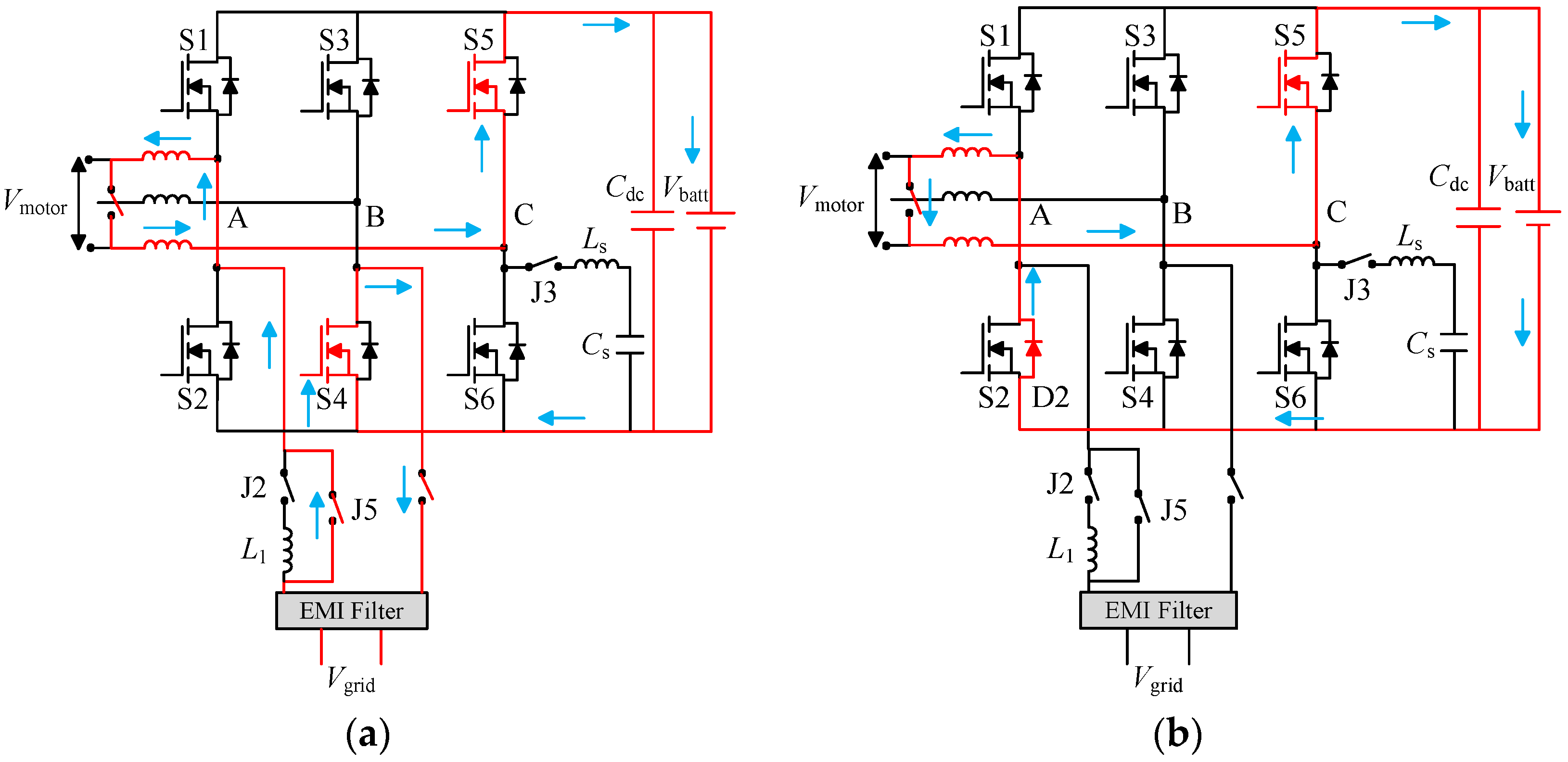
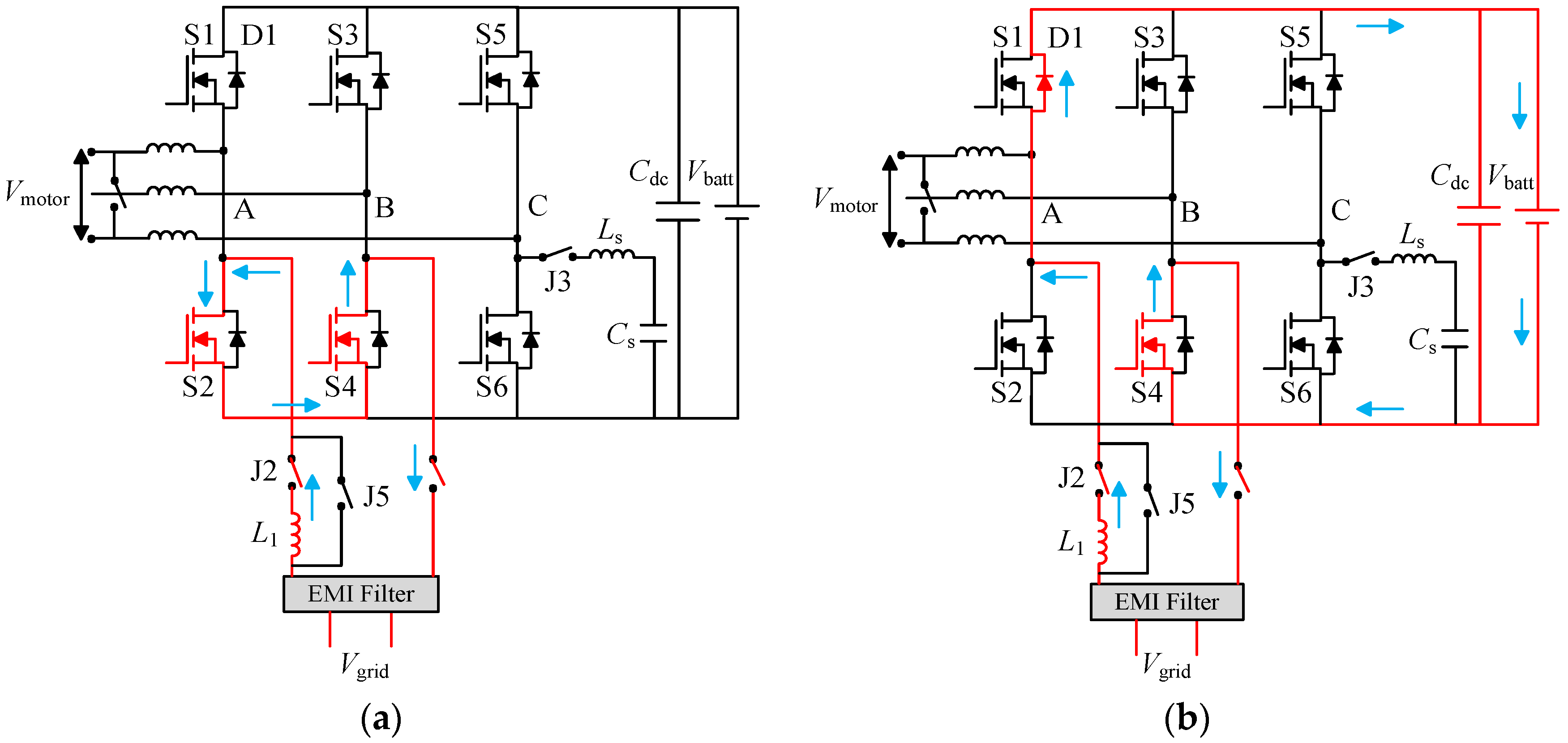
9]. From the perspective of power electronics, the on-board charger for an EV consists of an AC/DC power converter and some filter components. An efficient solution to make a high power density system is integrating the charger unit with motor drive converter. In the case of using an integrated charger, as illustrated in Figure 2, it is viable to share the same power switching devices and passive components because motor drive mode and battery-charging mode do not happen at the same time [10]. This configuration can effectively reduce the size and cost of the overall system. Meanwhile, with the DC/DC buck/boost charging capability, it enables operating with a wide charging range. In addition, essential capabilities such as buck for the battery voltage in motor drive mode and boost for the battery voltage in regenerative braking mode can be achieved as well [11]. Consequently, the conventional configuration consists of at least two individual converters for two independent operation modes.
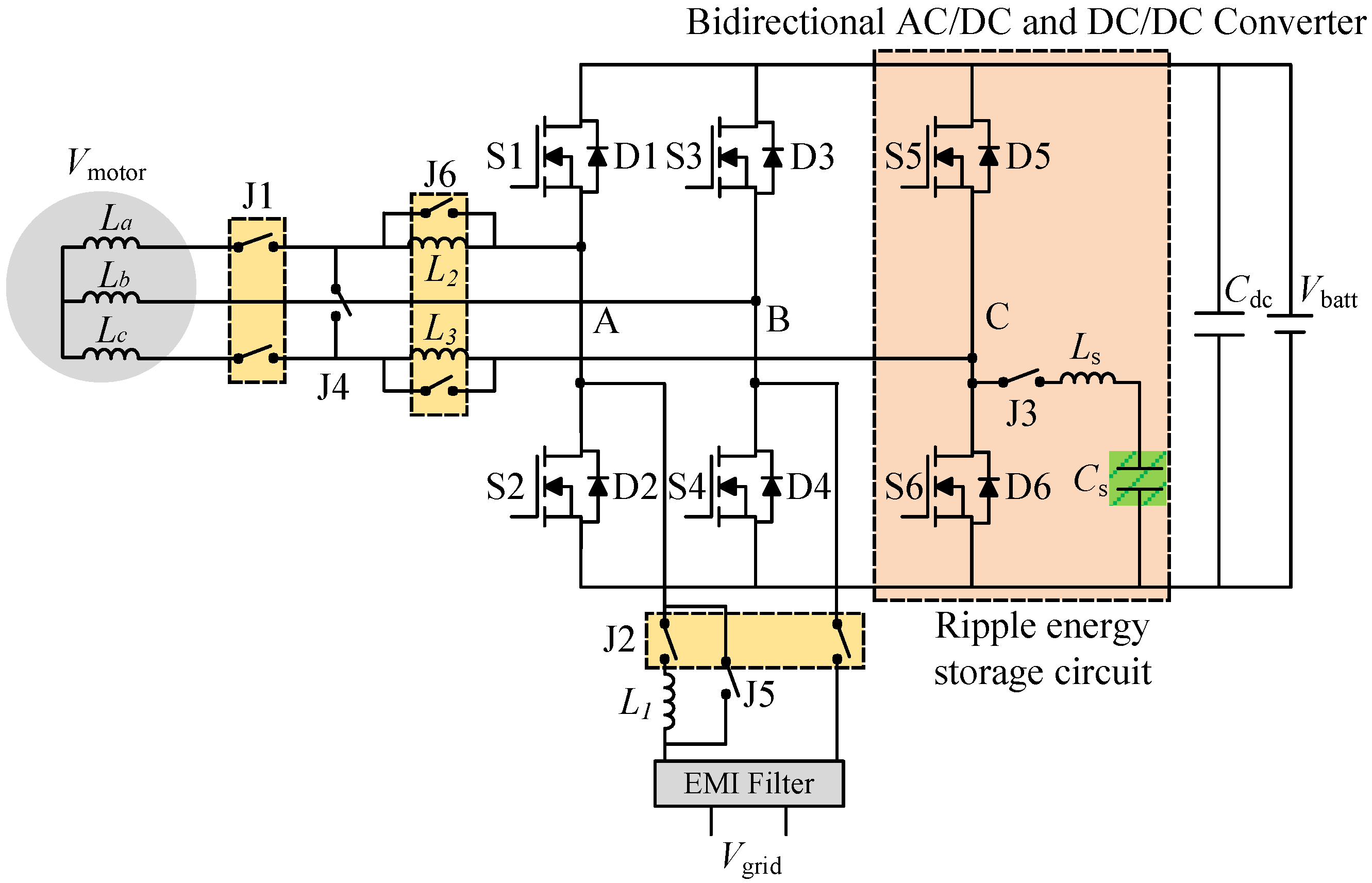
In order to obtain a simple and low cost design, transformer-less topology is used in the proposed integrated charger [12]. Compared with traditional design, which has a transformer at the AC grid side, the transformer-less topology will improve the efficiency, reduce the total weight and allow for less complicated control. In this paper, an integrated bidirectional AC/DC and DC/DC converter is proposed to implement the integration of EV with a household electric system. The system configuration and five operational modes principles are illustrated and the pulsating power reduction circuit is presented. The control schemes are described and compared for the battery-charging mode in order to achieve a better performance.
This paper is organized as follows: Section 2 introduces the proposed topology and explains the modes of operation in details. The utilized control schemes are illustrated in Section 3. The simulation and experimental results are presented in Section 4. In addition, power loss, system efficiency and thermal stress calculation results are presented in this section. Finally, Section 5 summarizes the study based on the achieved results.

2. Proposed Integrated Charger Topology and Operation Modes

Conventional electric drive system contains a DC/AC converter while the battery-charging system includes an AC/DC converter. The proposed converter enhances them into an integrated multifunctional bidirectional AC/DC and DC/DC converter, which can also charge the battery from DC power sources such as micro-grid. Proposed integrated charger topology is shown in Figure 2 based on the operating conditions. The proposed structure contains one electric motor, one input inductor, one electromagnetic interference (EMI) filter, one DC-link capacitor, six power switching devices, six diodes and six set relays, which are used to switch operating modes.
The batteries can be charged by the external power supply. When in charging mode, the motor needs to be disengaged for safety purposes. Therefore, relay J1 can disconnect the motor and converter physically from the battery-grid side, ensuring the EV is not powered in battery-charging mode. Proposed integrated charger has five basic modes, namely, motor drive mode, AC/DC battery-charging mode, regenerative braking mode, DC/DC battery-charging mode and V2G mode. The energy flow in each mode are summarized in Table 1.

2.1. Motor Drive Mode

The motor drive mode is buck operation from the battery to the traction motor. In this mode, Vbatt and Vmotor sequentially become input and output voltage, respectively. Phase A, B and C use a three-phase inverter as buck circuit. Power flow from the battery to the traction motor can be transferred by buck chopper. A 30 kW surface-mounted permanent magnet synchronous motor is used for motor drive operation. The rated rotor speed and rated torque are 3000 rpm and 100 Nm, respectively.

2.2. AC/DC Battery-Charging Mode

The battery pack can be charged by the grid power supply. In boost operation for AC/DC battery-charging mode, unipolar modulation is selected to control the single-phase converter, as shown in Figure 3.
The input inductance is calculated based on the current ripple on the inductor. The ripple current can be estimated based on the worst case ripple current. The relationship of current ripple, input inductance and DC bus voltage can be expressed in Equation (1):
I p e a k = U d c × U sin ω t U d c × ( 1 U sin ω t U d c ) 2 × L × f s
C = U 2 I 2 4 + ω 2 L 2 I 4 4 2 × U d c × Δ U d c × ω
where, Udc is the DC bus voltage, Usin(ωt) is the instantaneous value of gird side voltage and fs is the switching frequency.
In AC/DC battery-charging mode, the integrated converter operates as a single-phase pulse-width modulation (PWM) rectifier. H-bridge is dominant topology for Level 2 application low voltage and current requirement. Besides the charging capability, high performance, including low output current harmonic injection to the grid, is essential [13,14]. The energy passes the input inductor and then the H-bridge finally charges the DC capacitor. The input inductor is designed based on the current ripple on the inductor. Around 10% of the peak output current is used to determine the inductance. The correlation between the DC bus voltage, input inductor and current ripple is described in Figure 4a.
Considering the DC bus capacitor, the fairly large bus capacitor needed to smooth the DC voltage can be expressed by Equation (2). A single-phase PWM converter has a simple structure, higher efficiency, fewer components and lower cost in comparison to a three-phase converter. The only drawback is the ripple power pulsating with twice the grid frequency [15]. At steady state, the current and voltage of capacitor absorbing ripple energy can be expressed as Equations (3) and (4):
I C = I C ¯ × cos ( 2 ω o t + φ + γ )
V C = I C ¯ × sin ( 2 ω o t + φ + γ ) × ( 2 ω o L ) + I C ¯ × sin ( 2 ω o t + φ + γ ) × ( 1 2 ω o L ) + V d c ¯ = X × sin ( 2 ω o t + φ + γ ) + V d c ¯
where, φ is the phase angle, X is the impendence, VDC is the DC bus average voltage and L is input inductance.
The integrated converter should meet all the demands from IEEE-1547, SAE-J2894 and IEC-1000-3-2 standards [16,17]. However, the second-order harmonic current and corresponding ripple voltage will produce harmonic pollution in grid. Based on the above analysis, DC ripple current reduction circuit on single-phase voltage source PWM rectifier will play an important role to solve harmonic between converter and the grid. In addition, battery is expected to meet criteria in terms of long cycle life while maintaining most of its capacity at end of life. The 2ω0 pulsating power may cause battery heat generation imbalance. The relationship among power factor angles, 2ω0 ripple energy and supply frequency is shown in Figure 4b. Several methods have been explored to deal with this second-order ripple power from the single-phase application. These methods are summarized into inductive and capacitive energy storage shown in Figure 5.
For both single-phase rectifier portion and the ripple reduction circuit, a 20 kHz triangular modulation signal is generated. The power devises on U-phase and V-phase are used for the PWM operation, where VU denotes U-phase control signal, VV represents V-phase control signal, Vtri denotes triangular modulation signal, iU is U-phase current and VUV represents the effective value of input voltage. Figure 6 shows the typical waveforms of proposed PWM rectifier. Figure 7 shows the gate signal of VU, VV and Vtri during one switching cycle. The sum of U-phase duty cycle and V-phase duty cycle is always equal to 1.
The method using capacitor as ripple energy storage component is illustrated and calculated in [18]. The inductor is found to be not as good as a capacitor in terms of energy density for integrated charger application. Therefore, the capacitive ripple energy storage method is selected in this paper.
Constant current-constant voltage (CC-CV) charging method is selected in this paper. Battery-charging typically follows a two-phase approach. In the first phase, constant current is used to charge the battery. When the battery reaches a specified set-point voltage, the charging circuit provide only enough current to maintain the voltage at set-point voltage. The CC-CV battery-charging method profile is shown in Figure 8.

2.3. Regenerative Braking Mode

The limitation of driving range is the key restriction for development of EVs. Regenerative braking is an effective approach to extend the driving range of electric vehicles. Regenerative braking is the process where some of the kinetic energy stored in the vehicle transfer into electric energy in the battery during deceleration. Generally, the back electromotive force (EMF) is not high enough to directly charge the battery, and a bidirectional converter is necessary to realize the energy transferring between the vehicle and the battery. Regenerative braking operation is achieved through boost circuit. Throughout this mode, the braking energy can charge the battery because of insulated gate bipolar translator (IGBT) or metal oxide semiconductor field effect transistor (MOSFET) bidirectional conduction character. The boost operating mode during regenerative braking is similar to the drive motor but in reverse direction. When the battery state of charge (SOC) is considered, it is needed to protect the battery from overcharging, which affects the battery life. To protect the battery from damage caused by large charging currents during regenerative braking, the charging current should be limited in circumstances of braking under maximal feedback power and maximal feedback efficiency. Meanwhile, recovering as much braking energy as possible in order to improve the energy utilization efficiency is required. In order to explain regenerative braking operation, the operation of PM motor in the four quadrants of the torque-speed plane and operation modes are shown in Figure 9.
When PM motor is operated in the first and third quadrant, the supplied voltage is greater than the back EMF, which are forward motoring and reverse motoring modes, respectively, but the current direction flow differs. When the motor operates in the second and fourth quadrant, the value of back EMF generated by the motor should be greater than the supplied voltages, which are the forward braking and reverse braking modes of operation, respectively, the current flow is reversed as well. The PM motor is initially made to rotate in clockwise direction under propulsion mode, but when the speed reversal command is obtained, the control goes into the clockwise regeneration mode.

2.4. DC/DC Buck/Boost Battery-Charging Mode

A three-phase DC/DC converter is formed by the power devices and passive components. By controlling S1–S6, either a buck DC/DC converter or a boost DC/DC converter can be configured to meet the different voltage levels of the power source and batteries requirement. The battery pack can be charged by high-voltage DC power from DC micro-grid. A DC/DC buck operation is required between the battery and the DC power source.
The topology has a buck (step-down) characteristic, the DC source voltage should be higher than the Vbatt. There are two basic working states, as illustrated in Figure 10. S5 keeps conductive both in working stage 1 and working stage 2. In working stage 1, only S4 conducts. The inductors in A-phase and C-phase can be used in series as a part of DC/DC converter. The DC source discharges the energy to the batteries. In working stage 2, S4 stops conducting, while D2 continues conducting. The inductors in A-phase and C-phase discharge the energy to the batteries.
When the DC source voltage is lower than the battery voltage, a buck circuit is necessary between external power source and battery pack, as illustrated in Figure 11. Switching S4 maintains turn on, and S2 is kept at open-state in working stage 1. The DC source discharges the energy to the inductor L1. In working stage 2, S2 is turned off, and D1 is turned on. The inductor L1 discharges the energy to the battery pack.

2.5. Vehicle-to-Grid (V2G) Mode

Bidirectional converter not only charges EVs’ battery pack but also operates EV in V2G mode. The integrated converter operates as an inverter to control the battery feeding real power to the grid. V2G is a way of connecting the EVs to the power grid properly and utilizing battery power to meet the grid requirement. It can improve the efficiency of power utilization by filling the valley of electric power demand at night [19]. In addition, V2G function can supply power to the grid, it imposes to follow IEEE standard 1547-2003 [20].
Based on the vector relationship analysis, the integrated charger with AC/DC battery-charging mode and V2G mode is able to be operated on all four-quadrants, as shown in Figure 12. In V2G mode, particularly, the bidirectional converter provides power back to the grid.

3. Control Scheme

3.1. Drive Control Strategy

The control strategy for motor drive is shown in Figure 13; the conventional proportional integral (PI) controllers including DC-link voltage out control loop and ac side current inner control loop are applied in the three-phase inverter circuit.

3.2. AC Power Charging Control Strategy

Line-frequency fluctuations appear in both active power and reactive power when the DC components in the AC voltage and AC current are considered. The line-frequency active power fluctuations will cause voltage ripple in the DC-link, which generate a second-order harmonic in the AC current. The impact of DC components on battery-charging system is illustrated in Figure 14.
The proposed control scheme based on AC/DC battery-charging mode is shown in Figure 2. The A-phase and B-phase are connected to the AC grid. The C-phase accomplishes the pulsation power compensation by calculating the 2ω0 pulsation power between the DC-link and the ripple energy storage capacitor Cs. The control block diagram of AC battery-charging mode is given in Figure 15.
The control block diagram of the single-phase rectifier is shown on the left side of Figure 15. The PWM controller is used to control the DC-link voltage through unity power factor operation at the AC grid side. A proportional-integral (PI) closed-loop control regulates the DC-link voltage Vdc at the required level. A feedforward command of load power consumption is added on the closed-loop control output in order to improve the Vdc performance. The phase information is obtained by phase-locked-loop (PLL). The compensation current produced by auxiliary circuit is sensed and filtered by a low-pass filter (LPF) to attenuate the switching noise. The generating current command amplitude is then multiplied by a normalized sin wave, which is acquired from PLL to the AC grid voltage. The final current command is* ensures the unity power factor operation of the single-phase PWM rectifier. The C-phase is designed for circulating the reactive power by producing a DC voltage and a 2ω0 sinusoidal voltage. The resulting 2ω0 current component and the DC voltage can compensate the 2ω0 pulsating power. The error of the output current is amplified by a proportional gain Kp1 and the line voltage is added to produce the final voltage reference for the PWM. The control block is shown on the right side of the Figure 15. The inductor in auxiliary circuit is required to operate in continuous conduction mode (CCM). In order to operate in CCM mode, it is essential to determine the minimum inductance value ensures CCM operation [21]. The compensate current produced by pulse power reduction circuit ics can be constructed by creating a sine wave of frequency 2ω0 with C-phase shift and the amplitude ics. Simple proportional gain Kp4 amplifies the current error and then bias voltage Vbatt is added to produce the final voltage reference of the C-phase PWM waveform.

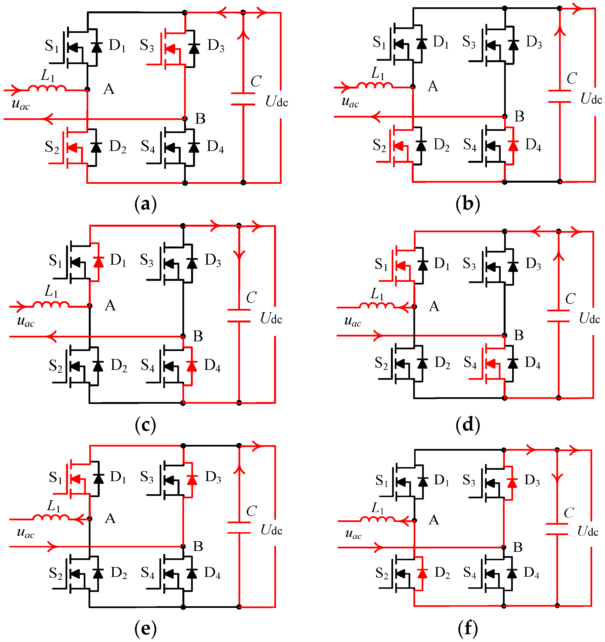
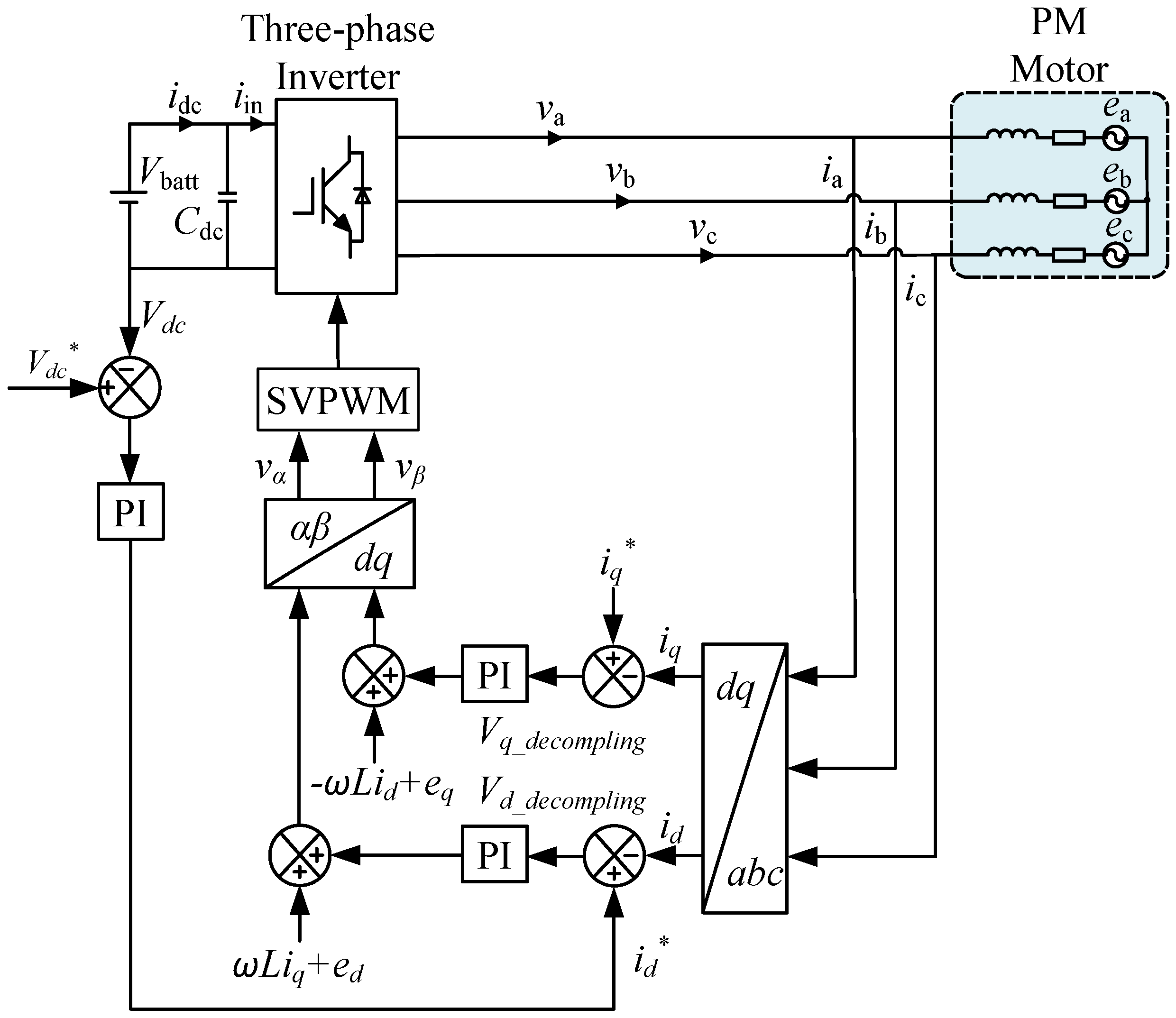
4. Simulation Results

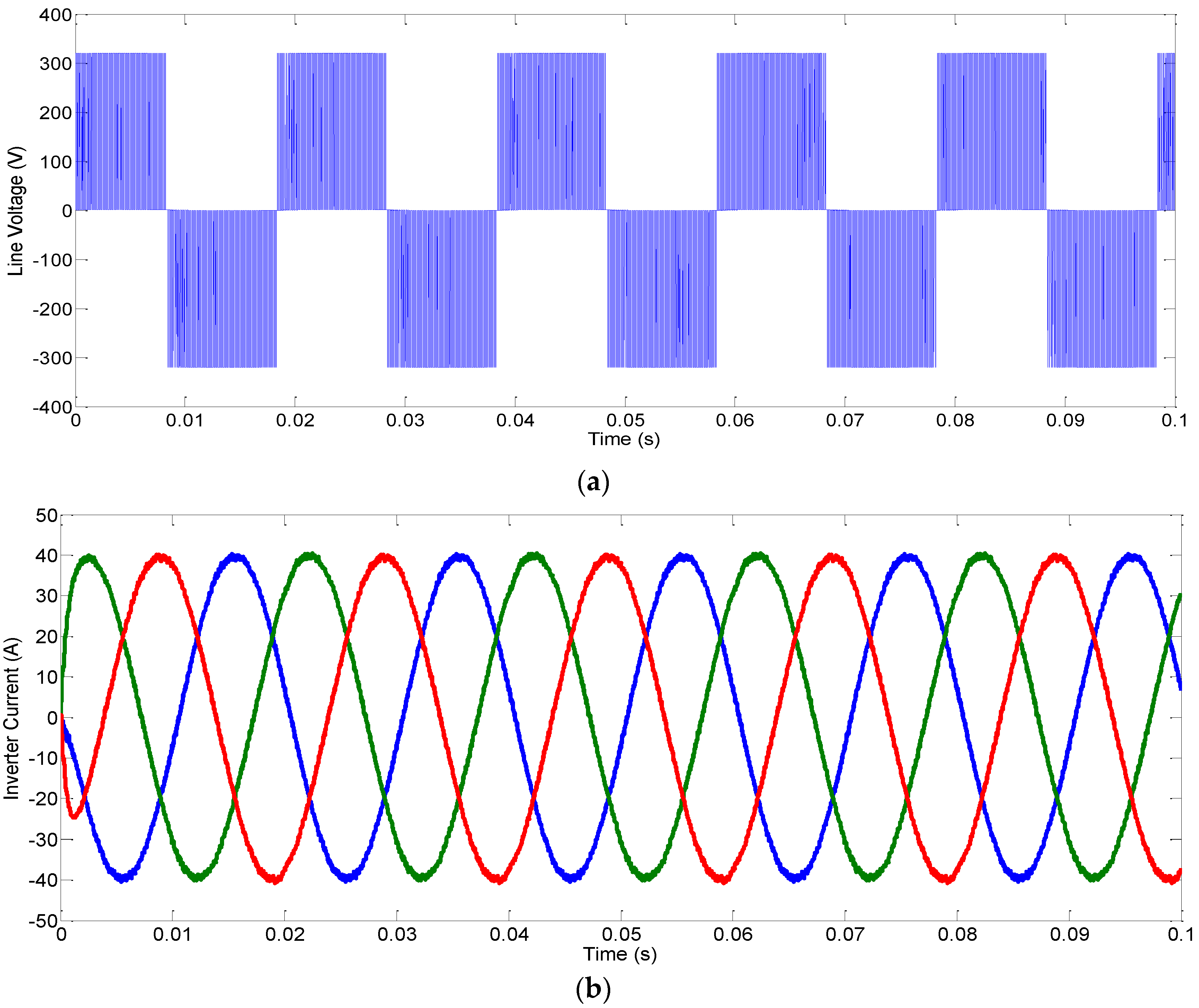
Space vector pulse width modulation (SVPWM) is acquired to conduct on the permanent magnet synchronous motor drive control. The motor drive mode performance is shown in Figure 16.
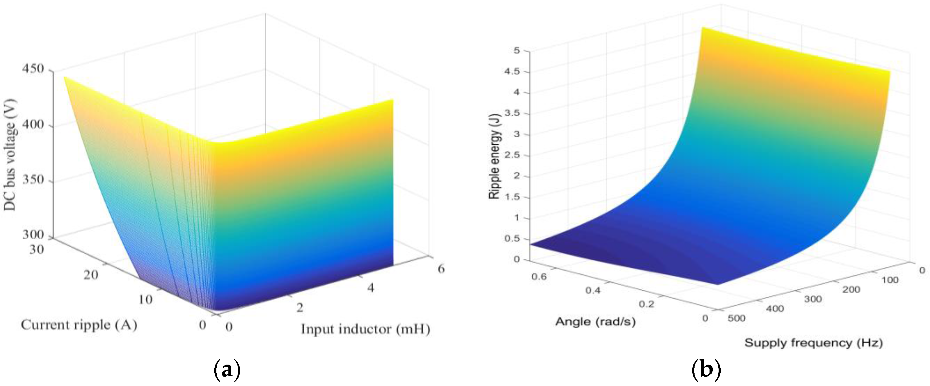
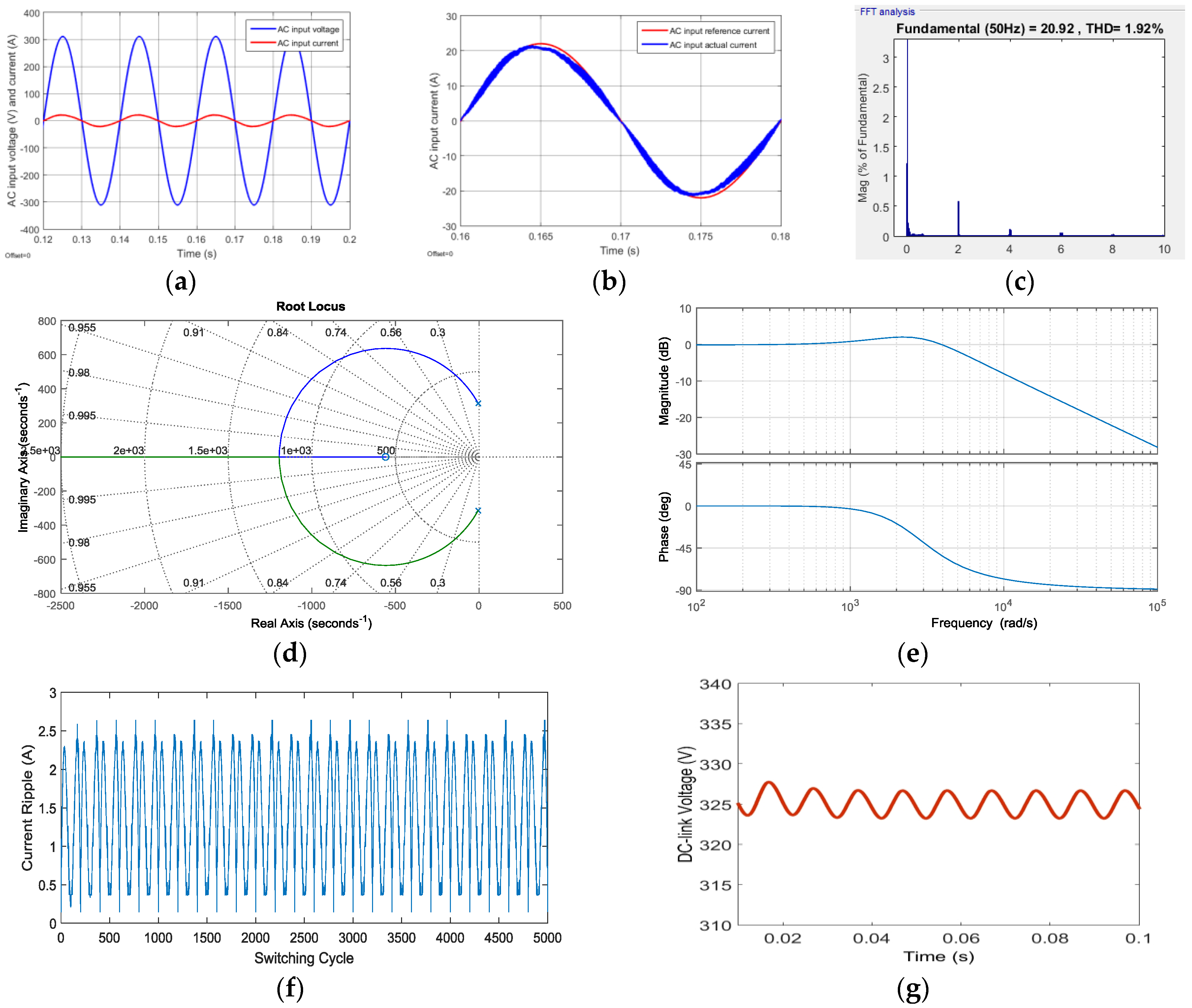
To evaluate the performance of the proposed integrated charger, AC battery-charging mode simulation has been performed. The input inductance is selected as 3 mH. To leave some margin, the root-mean-square (RMS) ripple current is 2.65 A, which is 10% of the peak output current (23.57 A). In order to show the advantage of the proposed auxiliary circuit method, simulation with ripple compensation circuit is carried out. The simulation results are shown in Figure 17.
Simulations are carried out for AC battery-charging mode of the proposed integrated charger with the parameters shown in Table 2. As mentioned in the previous section, the auxiliary capacitor Cs is selected as 298 µF. The auxiliary inductor Ls is selected as 50 µH. The DC bus capacitor is selected as 50 µF. By using MATLAB/Simulink as a simulation tool, the ripple energy from the ac side of the single-phase rectifier is verified to store in the auxiliary capacitor Cs effectively. Using the conventional method, a 4.665 mF capacitance is selected to meet the DC bus voltage ripple within 2% limit requirement. 
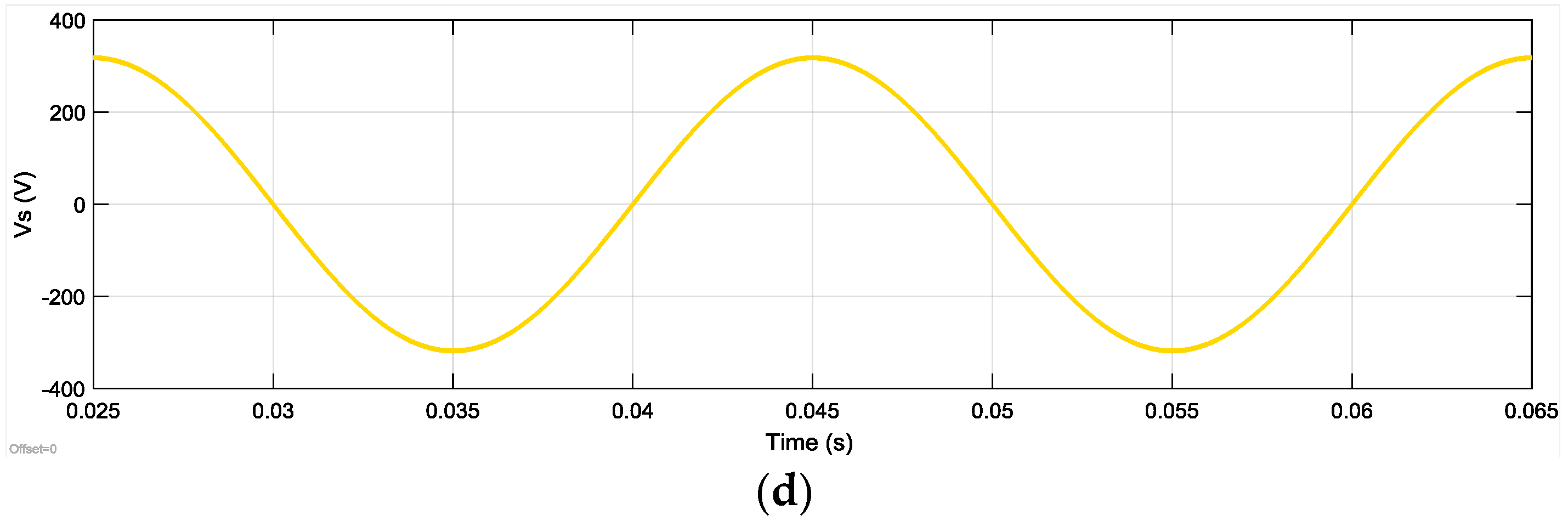
Figure 17a,b shows the AC input voltage and current, respectively. It should be noted the input current can track the reference value accurately. The total harmonic distortion is 1.92%, as shown in Figure 17c. The root locus of rectifier is given in Figure 17d. The root locus indicates the stability of system. The rectifier Bode plot is shown in Figure 17e. The large crossover frequency indicates the high frequency harmonic can be filtered at switching frequency. The maximum AC input current ripple is given in Figure 17f. It shows the maximum ripple is in accordance with unipolar modulation theoretical value. The DC-link output voltage is showed in Figure 17g.
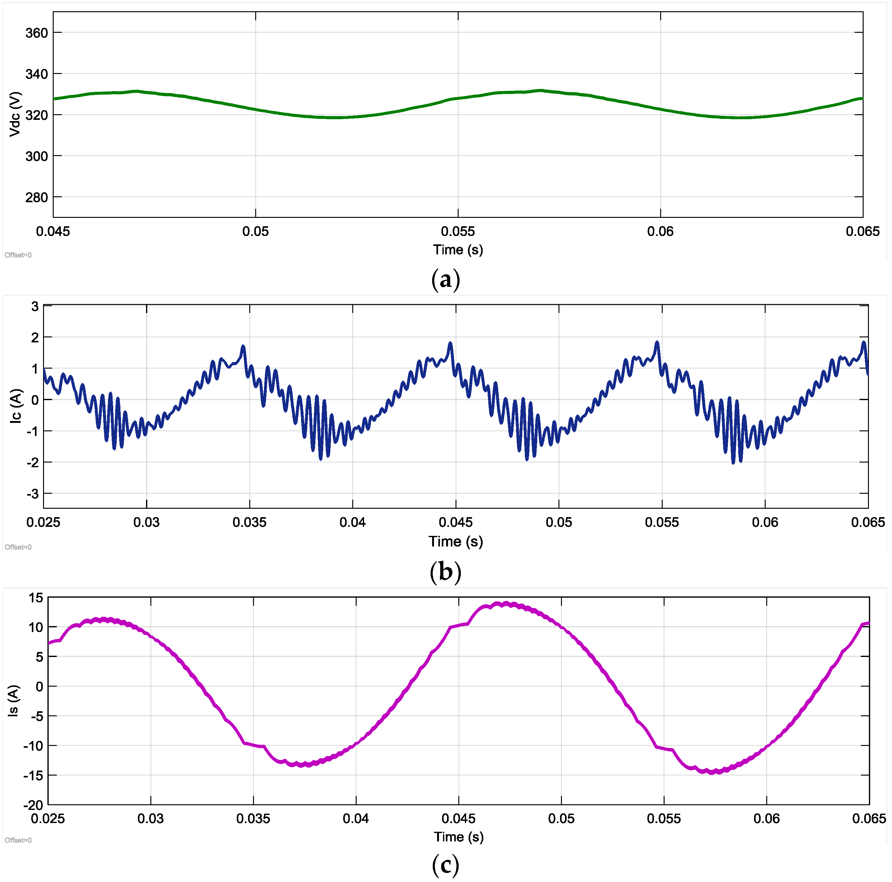
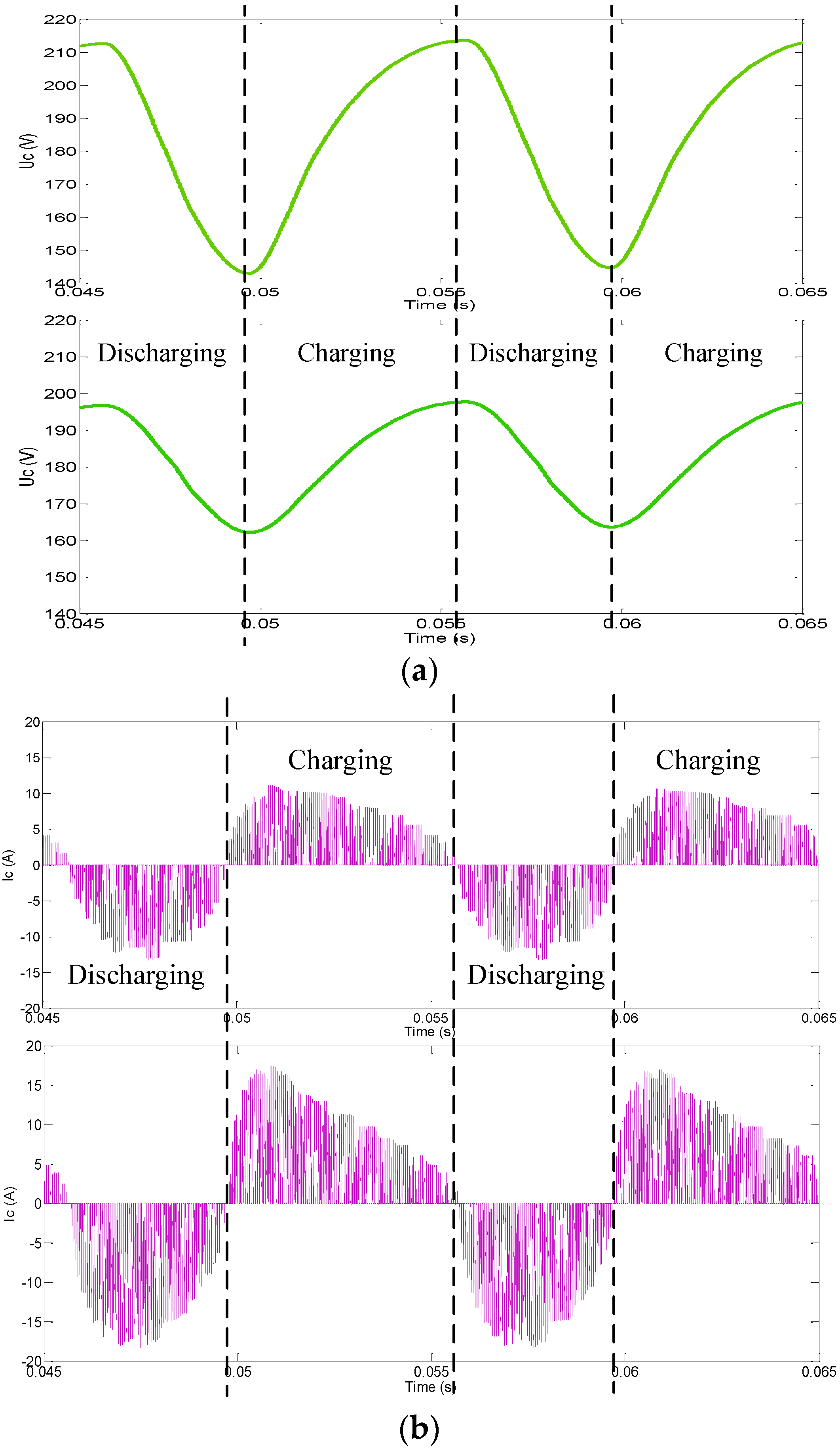
The simulation waveforms of AC battery-charging mode with active ripple energy storage circuit are presented in Figure 18. Charging power is selected to be compatible with SAE standard J1772 level 2 charging rate [22]. The method based on one digital signal control leads the auxiliary inductor work in continuous current mode. In addition, it provides a simple and comparatively low cost solution to implement integrated charger. The battery voltage waveform, auxiliary capacitor current, and grid side current are grid side voltage are presented in Figure 18.
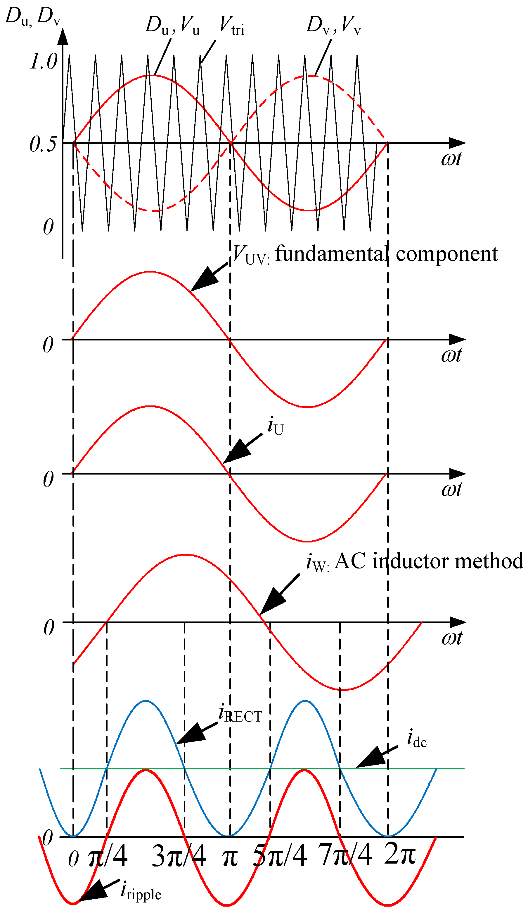
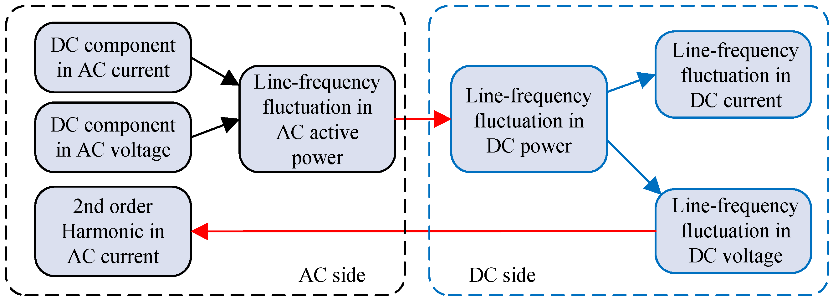
When the third leg is engaged, the 2ω0 pulsation power is absorbed by the auxiliary circuit. The ripple energy is stored in the auxiliary capacitor. The auxiliary inductor works as a ripple energy transfer component. The proposed control scheme successfully reduces the low frequency ripple energy back to the DC bus. The compensate circuit draws the low frequency current, the current flowing into the main dc capacitor contains high frequency component. Therefore, a small DC bus capacitor is still needed to maintain a smooth DC bus voltage. Figure 18b shows the auxiliary capacitor current. Significant 2ω0 ripple can be observed. In Figure 18c,d, the AC side voltage and current are illustrated. And the AC side current Is contains some distortion due to the input inductor.
High switching frequency can improve the active ripple energy storage circuit performance effectively. The results of the integrated converter simulations at 20 kHz are shown in the upper side of Figure 19, while the results of the integrated charger simulations at 73 kHz shown in the lower half of the Figure 19. As observed in Figure 19, by increasing switching frequency, the auxiliary inductance is selected as 30 µH in the system with the 73 kHz switching frequency. However, this will lead to a high current harmonic in auxiliary capacitor.
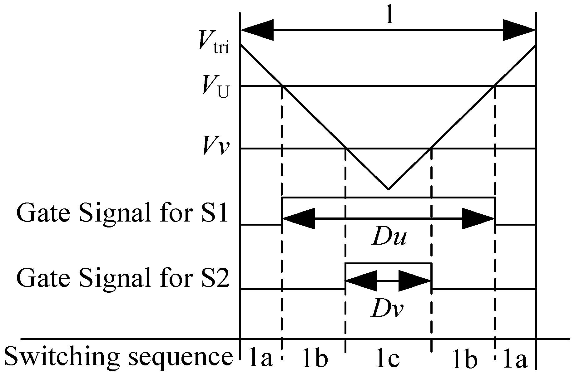
According to the comparison, there is a trade-off between one PWM signal control strategy and two PWM signals control strategy for auxiliary circuit. For the S5 and S6 control separately, it can achieve DCM, keeping the value of ripple energy transfer inductance at the minimum. In addition, its control scheme is more complex than one PWM signal control.
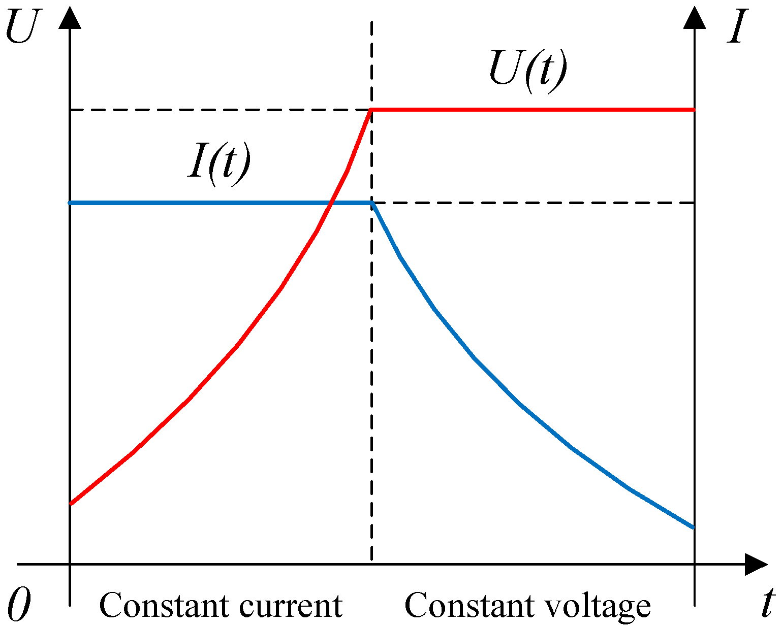
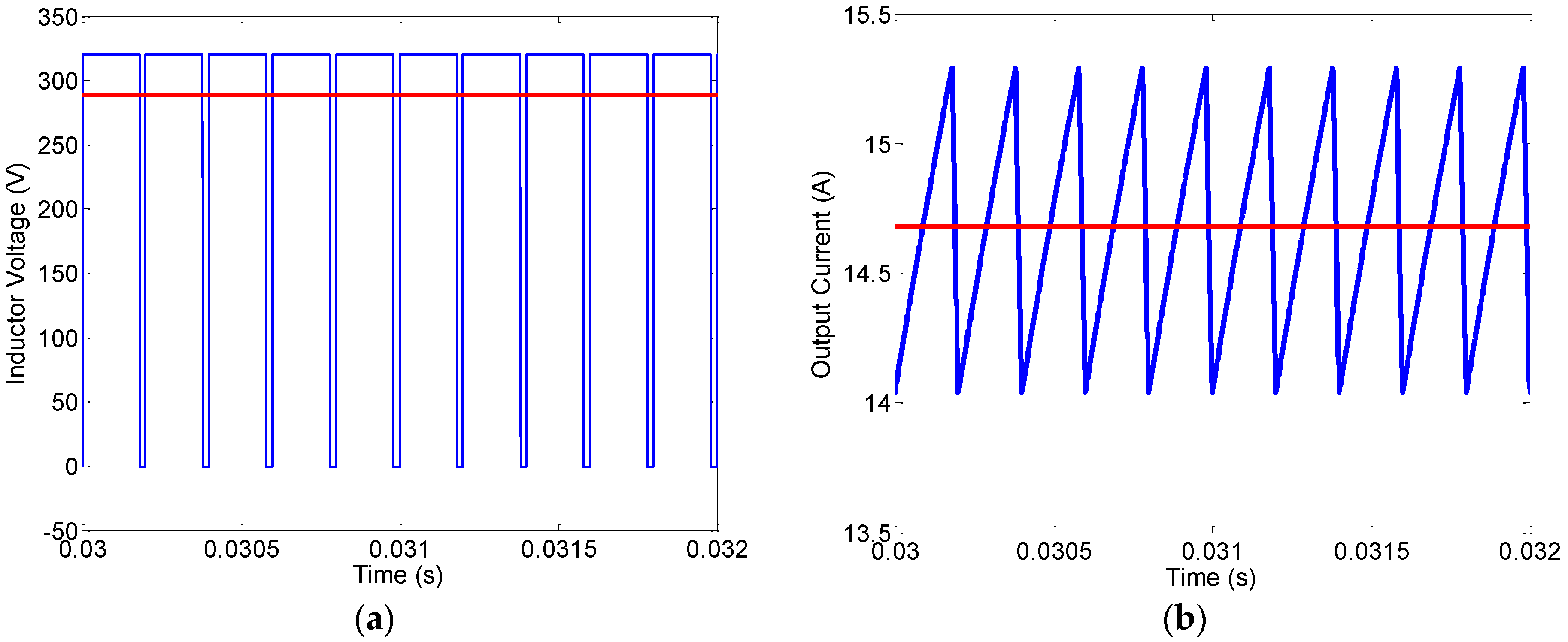
The steady states of DC/DC buck operation have also been simulated. The results for the DC external power source voltage of 400 V and the integrated charger is considered able to operate as a DC/DC buck converter, are shown in Figure 20. The inductor voltage and output current are shown in Figure 20, respectively. It is seen that the DC/DC buck operation can work properly.
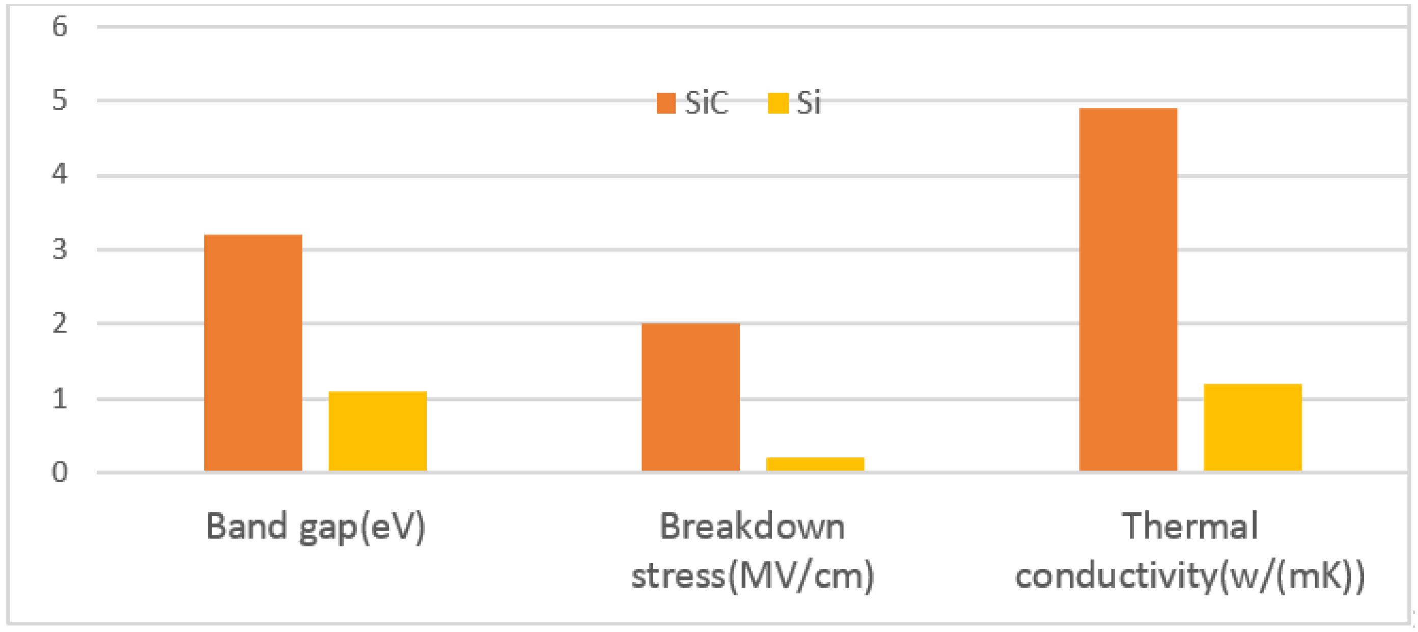
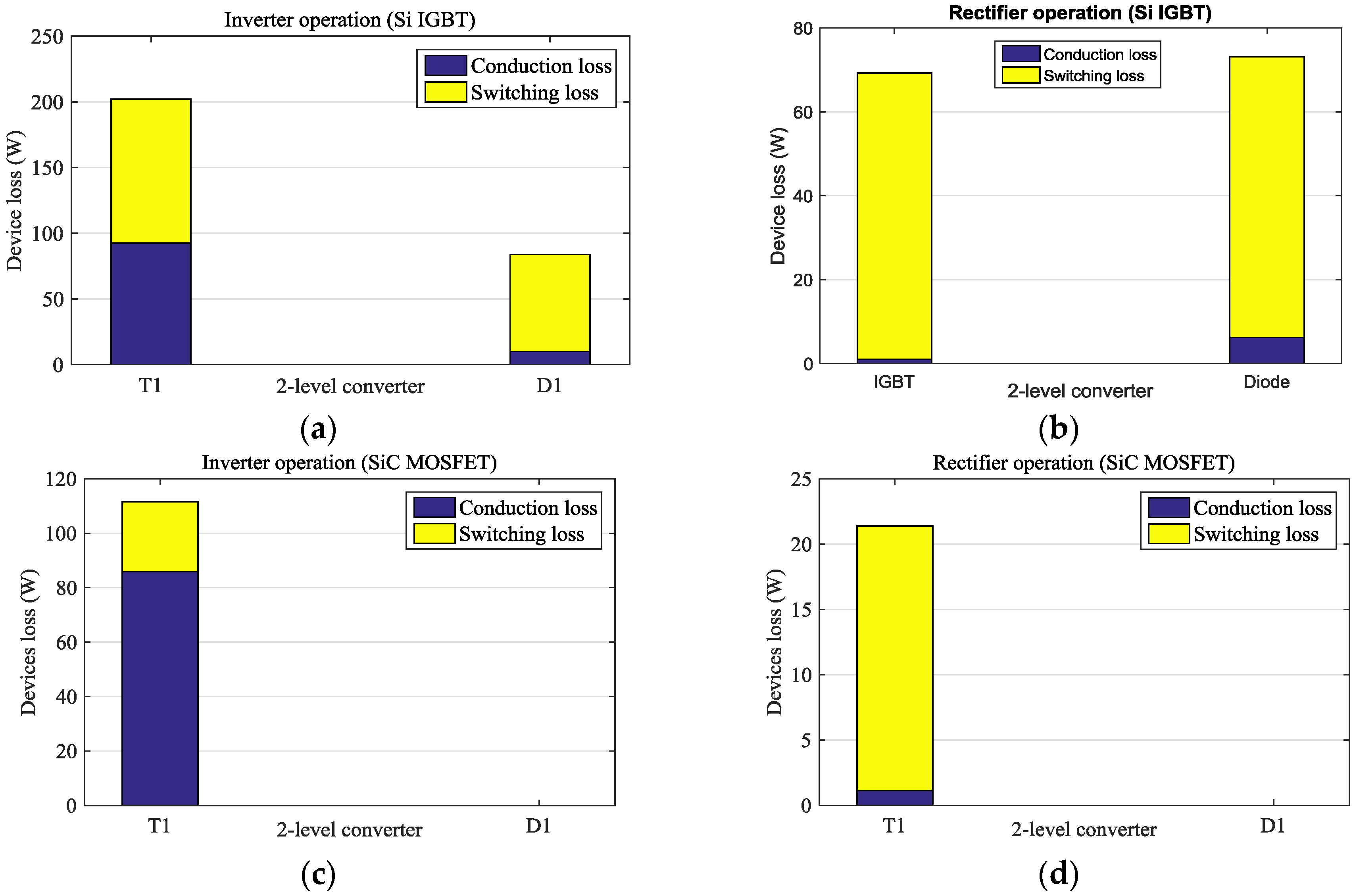
In this paper, two types of power devices are compared, i.e., silicon (Si) IGBT module and silicon carbide (SiC) MOSFET module. The state-of-the-art power devices are investigated for the integrated charger application. Wide-bandgap SiC material meet the demand for novel power semiconductor devices capable of operating at higher voltage, higher frequency and higher temperature. The comparison between Si and SiC material properties is shown in Figure 21. This section will develop the analytical averaged loss model for the power devices shown in Figure 2. The power loss and the efficiency variation with switching frequency of Si IGBT module and SiC MOSTFE module will also be investigated. Device characteristics are extracted from module datasheet.
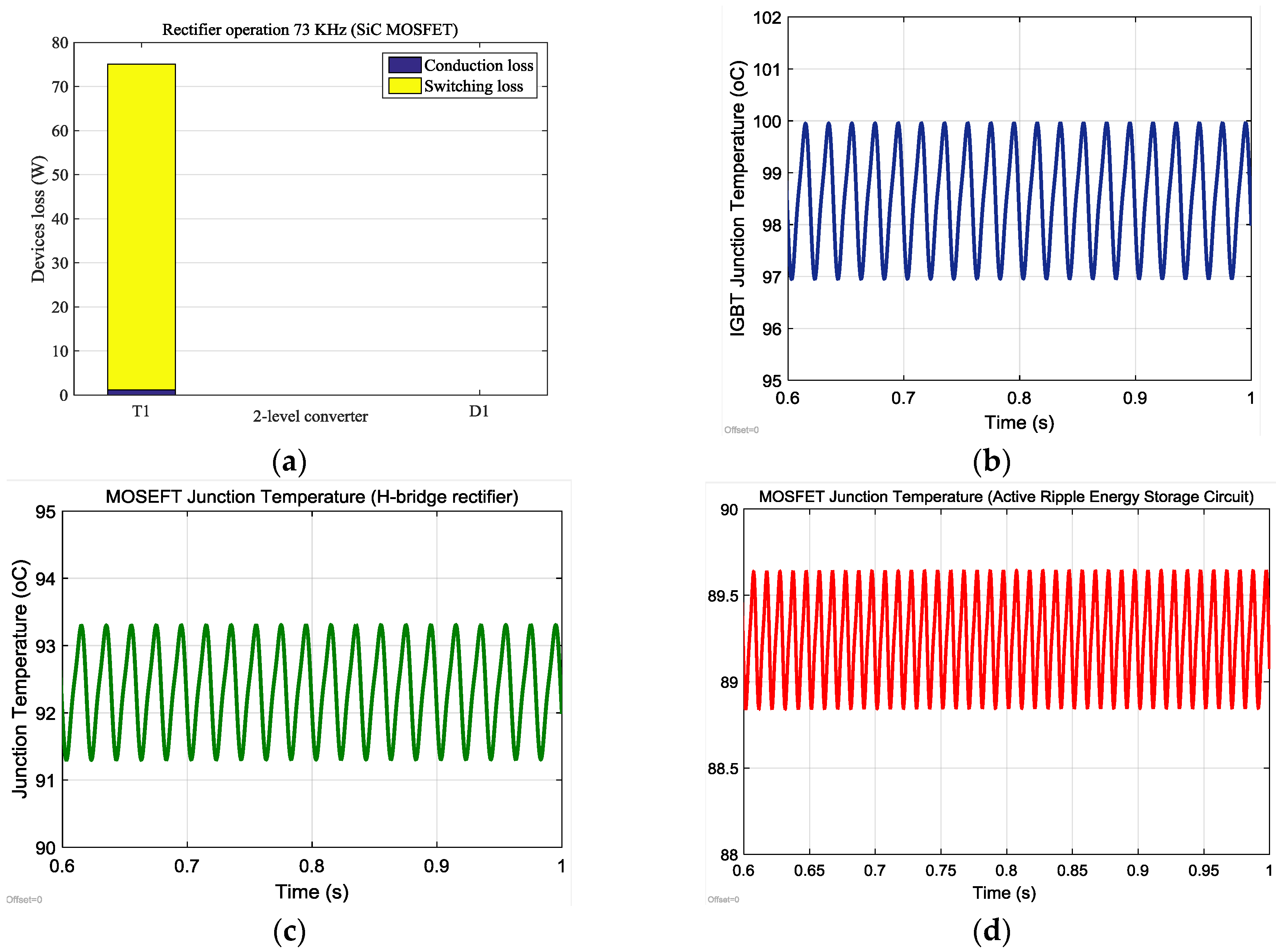
The switching device power loss can be characterized by the forward voltage drop during conduction and the turn-on and turn-off energy during switching. For simplification, the conduction characteristic of the devices is considered to be linear, which means on-state resistance is assumed as a fixed value. Due to the bidirectional current conductivity of the MOSFET channel, an assumption is made to simplify the calculation that MOSFET conduct all the load current throughout the period. In fact, the Schottky diode and the body diode share a part of the load current as well when the load current is negative. Based on above assumption, the conduction loss only occur in MOSFET. For Si IGBT and SiC MOSFET, the switching loss includes turn-on and turn-off losses. For diode, the switching loss only includes turn-off loss dissipated in the reverse recovery process. MOSFET is assumed to conduct all the load current during the negative current interval, but the switching loss still occur in the Schottky diode. Due to the existence of dead-time, load current flow to the Schottky diode, and then flow to the MOSFET. For SiC MOSFET manufacturers, it is claimed zero reverse recovery current, which means no reverse recovery loss for SiC module. The total loss is the sum of conduction loss and switching loss in all power devices. The devices used for comparison are Si IGBT module from SKM300GA12V (1200 V, 300 A, Semikron, Nuremberg, Germany) and SiC MOSFET module from CAS300M12BM2 (1200 V, 300 A, Cree, Durham, NC, USA). Figure 22 shows the loss distribution among the devices for rectifier and inverter operation with a modulation index of 0.9 and unity power factor. The full list of Si-based IGBT losses and SiC-based MOSFET losses are given in the appendix.
Figure 22a,b illustrates the power loss distribution in integrated converter applying inverter operation and rectifier operation, respectively. As shown in Figure 22a, the switching loss dominate 60% total power loss occur in Si IGBT. As shown in 
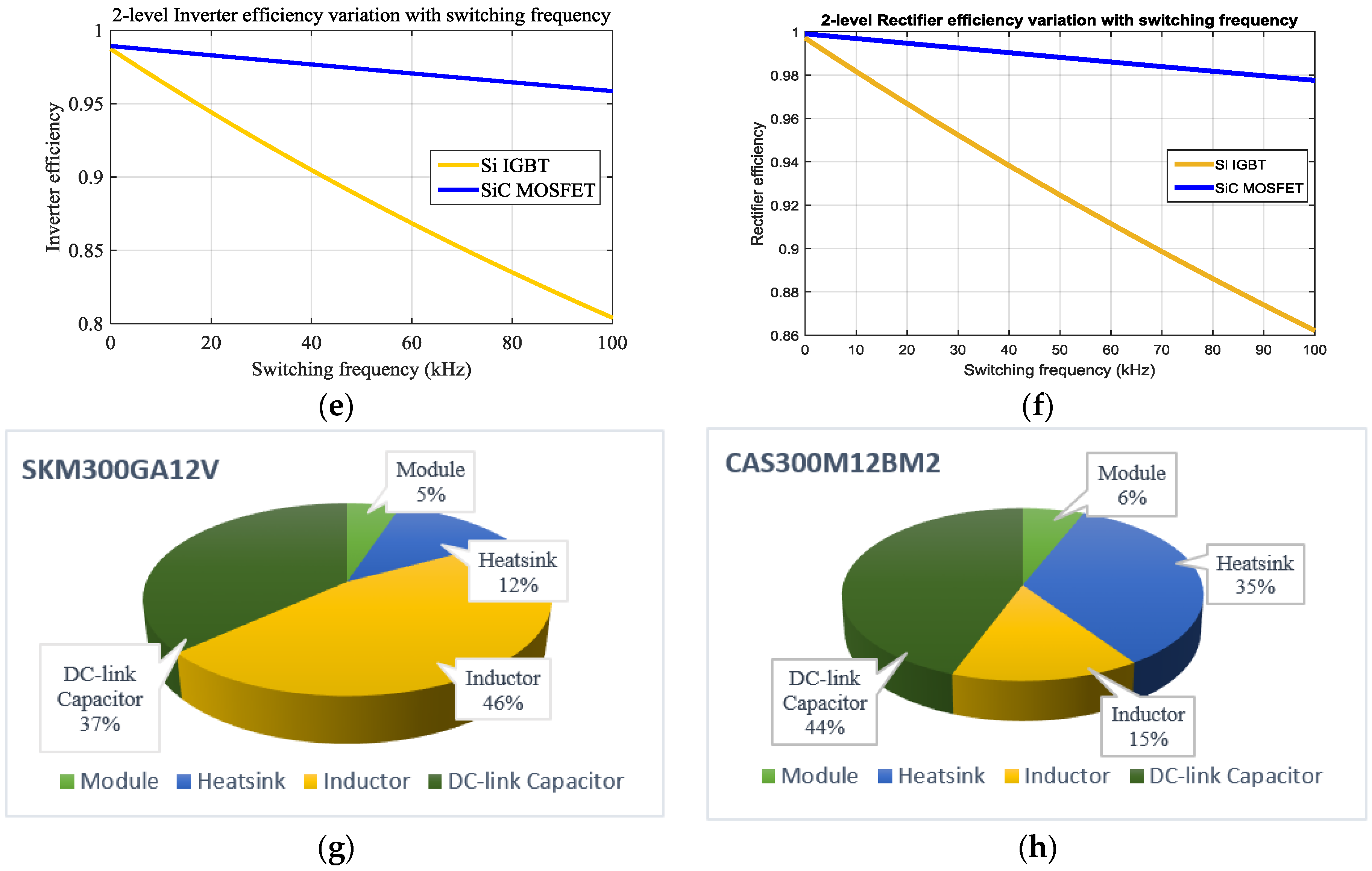
Figure 22c,d, it is assumed that all power loss occur only in MOSFET. It illustrates that SiC MOSFET have a good performance in reducing switching loss. The efficiency of Si-based module drop fast compared to SiC-based module with the switching frequency variation. Figure 22e,f shows the SiC MOSFET excellent performance and attractive potential in the applications of high switching frequency. At frequency above 20 kHz, the switching loss contribute to a significant amount of power dissipation [23]. The results for both Si and SiC converter volume breakdown are shown in Figure 22g,h. It should be noted that the switching frequency is 73 kHz for SiC converter and 20 kHz for Si converter. As can be seen, the inductor volume is reduced by approximately 31%. As expected, the volume of the converter decreases with switching frequency variation due to the good performance of SiC.
The junction temperature describes the temperature inside the chip, which is relevant for the loss and safe operating area. The power pulsation may cause extra thermal stress to the single-phase PWM power device and auxiliary circuit power device. In order to evaluate the thermal performance of the integrated converter, the power device junction temperature variation are simulated. Figure 23a shows H-bridge rectifier device power loss at 73 kHz, which indicates at frequency above 20 kHz, the switching loss contributes to a significant amount of power dissipation. Figure 23b–d shows the H-bridge and ripple energy reduction circuit device junction temperature variation. The Foster thermal network is used to calculate the junction temperature variation. The heatsink temperature is assumed to be fixed at 80 °C due to its large thermal time constant [24]. For the H-bridge, the IGBT temperature varies between 97 and 100 °C. When SiC MOSFET is used in single-phase, the MOSFET temperature various between 91.3 and 93.3 °C. When the auxiliary compensation circuit is applied, the MOSFET temperature varies between 88.8 and 89.7 °C. The larger junction temperature variation may reduce the lifetime of the power device. The thermal design should ensure the peak temperature is lower than the maximum allowance junction temperature.
High power density is one of the key motivations for the integration of power electronics components. Integrated converters are designed not only to meet the requirement of input and output, but also to achieve a light weight and a small size. The auxiliary ripple energy reduction circuit can also achieve a high power density, as discussed above.
In order to verify the effectiveness of the proposed system, an integrated multifunctional bidirectional AC/DC and DC/DC converter for electric vehicles has been implemented. The propulsion and AC/DC charging performances of the proposed topology and control schemes are verified in this paper.
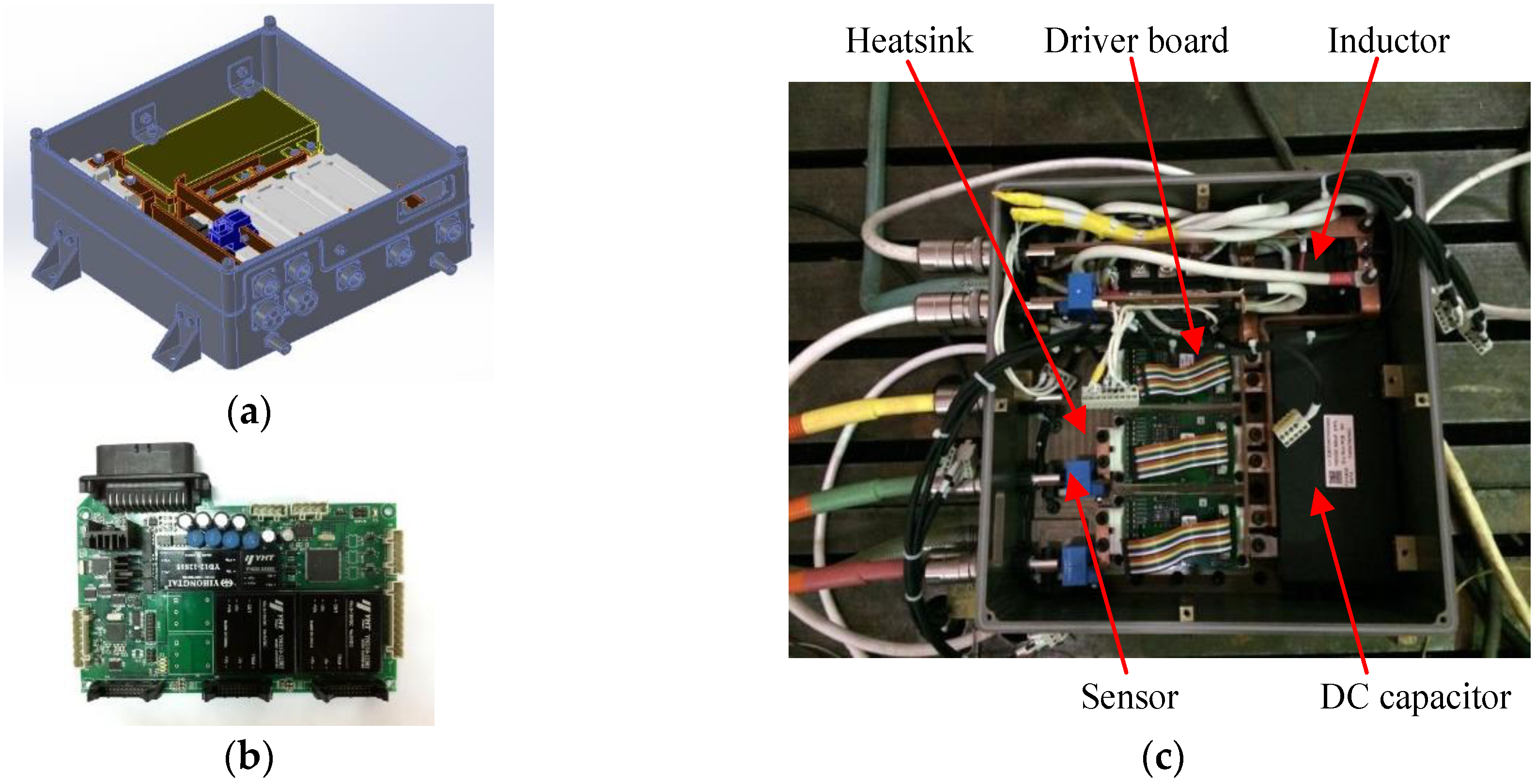
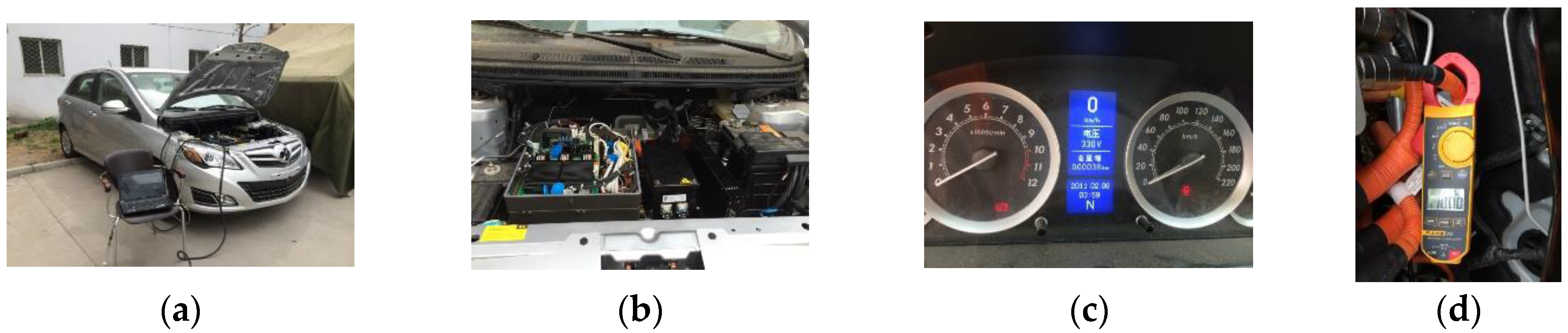
Figure 24a illustrates the system layout design. As mentioned earlier, power module, heatsink, controller, drive board, input inductor, DC capacitor and sensors are selected in the integrated converter. The controller is shown in Figure 24b. The photo of the experimental hardware prototype platform is shown in Figure 24c. The power module in the main power circuit is SEMIKRON SKM300GA12V with the maximum junction temperature 175 °C.
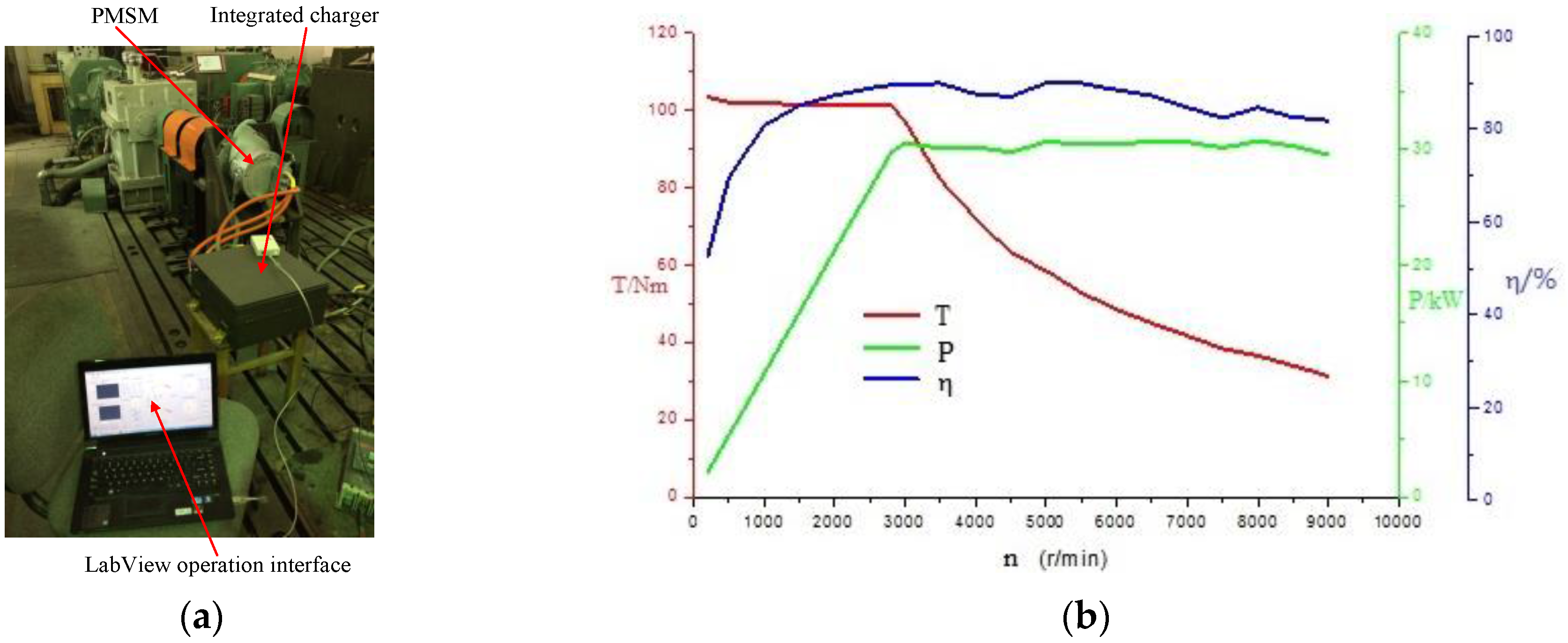
The motor driving operation photo of experimental prototype platform is shown in Figure 25a. The drive control method is implemented, as shown in Figure 25b. Figure 25b shows the rated speed is 3000 rpm, the rated torque is 100 Nm and the rated power is controlled as 30 kW, which are the same as the theoretical values.
Figure 26a,b shows AC/DC battery-charging operation experimental setup and results of the DC-link voltage and current. Figure 26c,d shows the DC-link voltage is 330 V and the load current is 10 A, respectively. Thus, the proposed charging control strategy can retain 3.3 kW charging power.
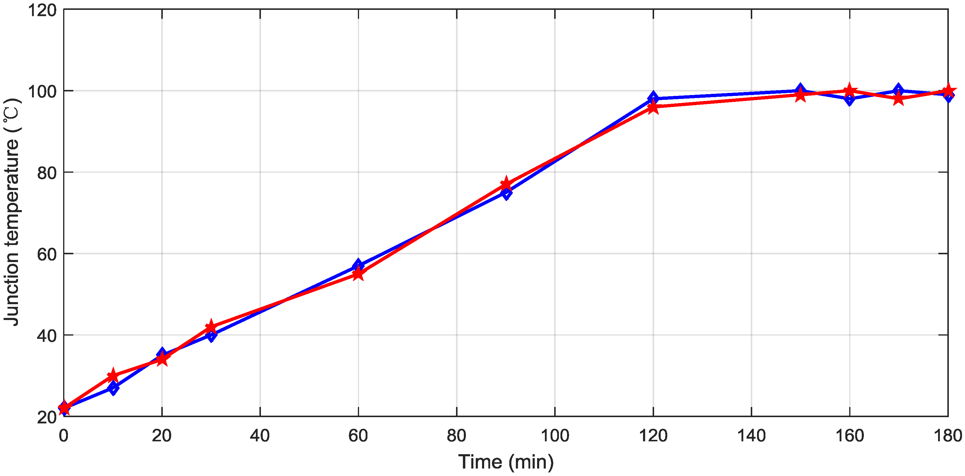
Figure 27 shows the rectifier device junction temperature variation. With AC/DC battery charging operation, the Si IGBT maximum junction temperature varies between 98 and 100 °C. The larger junction temperature variation may reduce the lifetime of the power device. The thermal design should also make sure the peak temperature does not exceed the maximum allowable junction temperature, 175 °C.

5. Conclusions

A SiC-based high power density integrated multifunctional bidirectional AC/DC and DC/DC converter for future application in electric vehicles has been proposed in this paper. The integrated converter infrastructure and operational principles have been described in detail. Additional details on converter passive components have been discussed. An improved control scheme has been developed and utilized to achieve better performance compared to DCM control in AC/DC battery-charging mode. Through the simulations, the functionalities for the three operating modes, i.e., motor drive mode AC/DC battery-charging mode and DC/DC battery-charging mode, have been verified. The simulation results show the feasibility of the design. The auxiliary circuit working as a parallel ripple current filter method achieves good performance. A simulation and 3.3 kW experimental test have been conducted for verification purpose. Meanwhile, in order to verify the proposed converter feasibility, the converter power loss, efficiency variation with switching frequency and thermal stress have been addressed. These results demonstrate the potential improvements in system performance.

Acknowledgments

This work was supported by the International Cooperation Research Program of China (No. 2015DFE72810), the Higher School Discipline Innovation Intelligence Plan (No. B12022) and the Beijing Municipal Science and Technology Commission of China (No. Z121100006612006).

Author Contributions

Liwen Pan conceived the topology and performed the simulations; Chengning Zhang conducted the experiment and analyzed the data; Liwen Pan wrote the paper.

Conflicts Of Interest

The authors declare no conflit of interests.

Appendix

Si-based IGBT loss calculation:
IGBT conduction loss P c o n . l o s s = ( 1 8 + m cos ( φ ) 3 π ) I C M 2 R + ( 1 2 π + m cos ( φ ) 8 ) I C M V C E 0 Diode conduction loss P c o n . l o s s = ( 1 8 m cos ( φ ) 3 π ) I C M 2 R + ( 1 2 π m cos ( φ ) 8 ) I C M V C E 0 IGBT (diode) switching loss P s w i t c h . l o s s = ( f s 2 π V s w i t c h V t e s t ) × ( π C 2 I C M 2 + 2 B I C M + π A )
where VCE0 denotes the device initial voltage drop, R represents the equivalent resistance to represent the linear region of device voltage drop, the modulation index is expressed as m, fs is the switching frequency, ICM denotes the load peak current and φ is the power factor angle.
SiC-based MOSFET loss calculation:
SiC MOSFET conduction loss P c o n . l o s s = I C M 2 R 4 Diode conduction loss 0 SiC MOSFET switching loss P s w i t c h . l o s s = ( f s 2 π V s w i t c h V t e s t ) × ( π C 2 I C M 2 + 2 B · I C M + π A ) Diode switching loss 0
where, A, B, and C describe the relationship between the switching energy and current. The parameters above can be identified from the device characteristics given in the datasheet or through experimental tests.

References

  1. Zhou, X.; Wang, G.; Lukic, S.; Bhattacharya, S.; Huang, A. Multi-function bi-directional battery charger for plug-in hybrid electric vehicle application. In Proceedings of the 2009 IEEE Energy Conversion Congress and Exposition, San Jose, CA, USA, 20–24 September 2009; pp. 3930–3936.
  2. Dusmez, S.; Khaligh, A. Compact and integrated multifunctional power electronic interface for PEVs. IEEE Trans. Power Electron. 2013, 28, 5690–5701. [Google Scholar] [CrossRef]
  3. Dusmez, S.; Khaligh, A. A novel low cost integrated on-board charger topology for electric vehicles and plug-in hybrid electric vehicles. In Proceedings of the 2012 Twenty-Seventh Annual IEEE Applied Power Electronics Conference and Exposition (APEC), Orlando, FL, USA, 5–9 February 2012; pp. 2611–2616.
  4. Dusmez, S.; Cook, A.; Khaligh, A. Comprehensive analysis of high quality power converter for level 3 off-board chargers. In Proceedings of the 2011 IEEE Vehicle Power and Propulsion Conference, Chicago, IL, USA, 6–9 September 2011; pp. 1–10.
  5. Zhou, X.; Lukic, S.; Kuang, A. A comparison of converter topologies for vehicle-to-grid applications: Three-leg converter versus H-bridge converter. In Proceedings of the Industrial Electronics Annual Conference of IEEE, Porto, Portugal, 3–5 November 2009; pp. 3711–3716.
  6. Trovao, J.P.; Pereirinha, P.G.; Trovao, L.; Jorge, H.M. Electric vehicles chargers characterization: Load demand and harmonic distortion. In Proceedings of the Electrical Power Quality and Utilisation (EPQU), Lisbon, Portugal, 17–19 October 2011.
  7. Zhou, X.; Lukic, S.; Bhattacharya, S.; Kuang, A. Design and control of grid-connected converter in bi-directional battery charger for plug-in hybrid electric vehicle application. In Proceedings of the 2009 IEEE Vehicle Power and Propulsion Conference, Dearborn, MI, USA, 7–10 September 2009; pp. 1716–1721.
  8. Dusmez, S.; Chen, C.; Khaligh, A. A reduced-part single stage direct AC/DC on-board charger for automotive applications. In Proceedings of the 2013 Twenty-Eighth Annual IEEE Applied Power Electronics Conference and Exposition (APEC), Long Beach, CA, USA, 17–21 March 2013; pp. 1791–1797.
  9. Dusmez, S.; Hasanzadeh, A.; Khaligh, A. Comparative analysis of bidirectional three-level DC-DC converter for automotive applications. IEEE Trans. Ind. Electron. 2015, 62, 3305–3315. [Google Scholar] [CrossRef]
  10. Vittorias, I.; Metzger, M.; Kunz, D.; Gerlich, M.; Bachmaier, G. A bidirectional battery charger for electric vehicles with V2G and V2H capability and active and reactive power control. In Proceedings of the Transportation Electrication Conference and Expo (ITEC), Dearborn, MI, USA, 15–18 June 2014.
  11. Joice, C.S.; Paranjothi, S.R.; Kumar, V.J.S. Digital control strategy for four quadrant operation of three phase BLDC motor with load variations. IEEE Trans. Inform. 2013, 9, 974–982. [Google Scholar] [CrossRef]
  12. Bobba, P.B.; Rajagopal, K.R. Modeling and analysis of hybrid energy storage systems used in electric vehicles. In Proceedings of the 2012 IEEE International Conference on Power Electronics, Drives and Energy Systems (PEDES), Bengaluru, India, 16–19 December 2012.
  13. Zhang, X.; Wang, Y.; Liu, G.; Yuan, X. Robust regenerative charging control based on T-S fuzzy sliding-mode approach for advanced electric vehicle. IEEE Transp. Electr. 2016, 2, 52–65. [Google Scholar] [CrossRef]
  14. Musavi, F.; Eberle, W.; Dunford, W.G. A high-performance single-phase AC-DC power factor corrected boost converter for plug in hybrid electric vehicle battery chargers. In Proceedings of the IEEE Energy Conversion Congress and Exposition, Atlanta, GA, USA, 12–16 September 2010.
  15. Cousland, A.W.; Ciaravolo, R.J.; Blieden, G.; Hosseinzadeh, N. Design of a battery charger and charging management system for an electric vehicle. In Proceedings of the Universities Power Engineering Conference (AUPEC), Christchurch, New Zealand, 5–8 December 2010.
  16. Bai, H.; Zhang, Y.; Semanson, C.; Luo, C.; Mi, C.C. Modelling, design and optimization of a battery charger for plug-in hybrid electric vehicles. IET Electr. Syst Transp. 2011, 1, 3–10. [Google Scholar] [CrossRef]
  17. Musavi, F.; Edington, M.; Eberle, W.; Dunford, W.G. Energy efficiency in plug-in hybrid electric vehicle chargers: Evaluation and comparison of front end AC-DC topologies. In Proceedings of the IEEE Energy Conversion Congress and Exposition, Phoenix, AZ, USA, 17–22 September 2011.
  18. Pan, L.; Zhang, C. A high power density integrated charger for electric vehicles with active ripple compensation. Math. Probl. Eng. 2015. [Google Scholar] [CrossRef]
  19. Xue, L.; Diaz, D.; Shen, Z.; Luo, F.; Mattavelli, P.; Boroyevich, D. Dual active bridge based battery charger for plug-in hybrid electric vehicle with charging current constaining low frequency ripple. IEEE Trans. Power Electron. 2015, 30, 7299–7307. [Google Scholar] [CrossRef]
  20. Xue, L.; Mattavelli, P.; Boroyevich, D.; Shen, Z.; Burgos, R. Closed-loop control on DC link voltage ripple of plug-in hybrid electric vehicle charger with sinusoidal charging. In Proceedings of the IEEE Energy Conversion Congress and Exposition, Denver, CO, USA, 15–19 September 2013.
  21. Kim, S.; Kang, F.S. Multifunctional onboard battery charger for plug-in electric vehicles. IEEE Trans. Ind. Electron. 2015, 62, 3460–3472. [Google Scholar]
  22. Awami, A.T.A.; Sortomme, E.; Akhtar, G.M.A.; Faddel, S. A voltage-based controller for an electric vehicle charger. IEEE Trans. Veh. Technol. 2015, 6, 4185–4196. [Google Scholar] [CrossRef]
  23. Yuan, X.; Lovett, A. DC-link capacitance reduction in a high power medium voltage modular wind power converter. In Proceedings of the 2013 15th European Conference on Power Electronics and Applications (EPE), Lille, France, 2–6 September 2013; pp. 1–10.
  24. Boroyevich, D.; Chen, A.; Luo, F.; Ngo, K.; Ning, P.; Wang, R.; Zhang, D. High-density system integration for medium power application. In Proceedings of the 2010 6th International Conference on Integrated Power Electronics Systems (CIPS), Nuremberg, Germany, 16–18 March 2010.
Figure 1. Electric vehicles (EVs) battery chargers classification by society of automotive engineers (SAE).
Energies 09 00493 g001
Figure 2. Proposed integrated bidirectional AC/DC and DC/DC converter.
Energies 09 00493 g002
Figure 3. Unipolar modulation process: (a) Capacitor charge battery, grid and capacitor charge inductor; (b) Capacitor charge battery, grid charge inductor; (c) Grid and inductor charge capacitor and battery; (d) Capacitor charge battery and inductor; (e) Capacitor charge battery; and (f) Grid and inductor charge capacitor, inductor charge battery.
Energies 09 00493 g003
Figure 4. (a) Relationship of input inductor, current ripple and DC bus voltage; and (b) Relationship among angle of the supply voltage, supply current and supply frequency.
Energies 09 00493 g004
Figure 5. Inductive and capacitive energy storage classification: (a) Inductive energy storage; and (b) Capacitive energy storage.
Energies 09 00493 g005
Figure 6. Waveforms of the pulse-width modulation (PWM) rectifier.
Energies 09 00493 g006
Figure 7. Gate signal of PWM rectifier.
Energies 09 00493 g007
Figure 8. Constant current-constant voltage (CC-CV) charging mode.
Energies 09 00493 g008
Figure 9. Operation of PM motor in the four quadrants of the torque-speed plane: (a) Four quadrants of operation; and (b) Operation modes.
Energies 09 00493 g009
Figure 10. DC/DC buck converter circuit operating phases: (a) S4 state-on; and (b) D2 state-on.
Energies 09 00493 g010
Figure 11. DC/DC boost converter circuit operating phases: (a) S2 state-on; and (b) D1 state-on.
Energies 09 00493 g011
Figure 12. Power control in all four-quadrants.
Energies 09 00493 g012
Figure 13. Control strategy for three-phase inverter.
Energies 09 00493 g013
Figure 14. Influences of DC component on battery charging system.
Energies 09 00493 g014
Figure 15. Control block diagram of integrated converter.
Energies 09 00493 g015
Figure 16. Simulation result: (a) Three-phase inverter output line voltage; and (b) Three-phase inverter output current.
Energies 09 00493 g016
Figure 17. Simulation result: (a) AC input voltage and current; (b) AC input current track error; (c) The system total harmonic distortion (THD); (d) Root locus; (e) System Bode plot; (f) Maximum AC input current ripple; and (g) DC-link output voltage.
Energies 09 00493 g017
Figure 18. Simulation result: (a) DC-link voltage; (b) The power decoupling capacitor current; (c) AC grid current; and (d) AC grid voltage.
Energies 09 00493 g018aEnergies 09 00493 g018b
Figure 19. Simulation result: (a) auxiliary capacitor voltage; and (b) auxiliary capacitor current.
Energies 09 00493 g019
Figure 20. DC/DC buck operation: (a) Inductor voltage; and (b) Output current.
Energies 09 00493 g020
Figure 21. Comparison between Si and SiC material properties.
Energies 09 00493 g021
Figure 22. Calculated results: (a) Si IGBT and diode loss in the inverter; (b) Si IGBT and diode loss in the rectifier; (c) SiC MOSFET loss in the inverter; (d) SiC MOSFET loss in the rectifier; (e) Inverter efficiency variation with switching frequency; (f) Rectifier variation with switching frequency; (g) Volume breakdown of Si IGBT converter; and (h) Volume breakdown of SiC MOSFET converter.
Energies 09 00493 g022aEnergies 09 00493 g022b
Figure 23. Simulation results: (a) SiC MOSFET loss in the rectifier (73 kHz); (b) Rectifier device (Si IGBT) junction temperature variation; (c) Rectifier device (SiC MOSFET) junction temperature variation; and (d) Auxiliary circuit device (SiC MOSFET) junction temperature variation.
Energies 09 00493 g023
Figure 24. Experiment setup built: (a) System layout; (b) Controller board; and (c) System hardware design structure.
Energies 09 00493 g024
Figure 25. Motor driving operation experimental setup and result: (a) Setup; (b) Results.
Energies 09 00493 g025
Figure 26. AC/DC battery charging operation experimental setup and results: (a) Setup; (b) Setup; (c) Current; and (b) Voltage.
Energies 09 00493 g026
Figure 27. Single-phase PWM rectifier (IGBT/diode) junction temperature variation.
Energies 09 00493 g027
Table 1. Operation modes of the proposed converter.
Operation ModeEnergy FlowMode
PropulsionVbatt to VmotorBuck
AC/DC Battery-ChargingVgrid to VbattBoost
DC/DC Battery-ChargingVdc to VbattBuck/Boost
V2GVbatt to VgridBuck
Regenerative BrakingVmotor to VbattBoost
Table 2. Simulation Parameters.
SymbolParameterValue
VsInput Voltage230 V/50 Hz
VbattBattery Voltage320 V
L1Input Inductance3 mH
fsSwitching Frequency20 kHz
CsAuxiliary Capacitance298 µF
LsAuxiliary Inductance50 µH
CdcDC bus Capacitance50 µF

