Article

A Novel Design of Radio Frequency Energy Relays on Power Transmission Lines

1
School of Electrical Engineering and Automation, Hefei University of Technology, Hefei 230009, China
2
School of Electrical and Automation Engineering, East China Jiaotong University, Nanchang 330013, China
*
Authors to whom correspondence should be addressed.
Energies 2016, 9(6), 476; https://doi.org/10.3390/en9060476
Submission received: 1 April 2016 / Revised: 18 May 2016 / Accepted: 13 June 2016 / Published: 21 June 2016
(This article belongs to the Special Issue Wireless Rechargeable Sensor Networks)

Abstract

:
In this paper, we investigate the energy problem of monitoring sensors on high-voltage power transmission lines and propose a wireless charging scheme for a Radio Frequency IDentification (RFID) sensor tag to solve a commercial efficiency problem: the maintenance-caused power outage. Considering the environmental influences on power transmission lines, a self-powered wireless energy relay is designed to meet the energy requirement of the passive RFID sensor tag. The relay can obtain the electric field energy from the transmission lines and wirelessly power the RFID sensor tags around for longer operating distance. A prototype of the energy relay is built and tested on a 110 kv line. The measurement results show that the energy relay can provide stable energy even with the influences of wind, noise and power outage. To our knowledge, it is the first work to power the RFID sensor tags on power transmission lines.

Graphical Abstract

1. Introduction

Electricity demand in China has been on the rise with the rapid development of modern industry, while the safety of high-voltage power transmission is becoming vital because of the large supply area of power substations [1]. However, there are many uncontrollable factors which need to be monitored in real time, threatening the safety of power transmission lines, such as harsh environments [2]. Thus, lots of devices, such as current sensors and temperature sensors [2,3], have been applied in practice. However, the electricity quantity and operation life of power sources in these devices will influence the commercial efficiency of the monitoring system.
A battery is a common choice to power the monitoring devices, but in a power transmission system, the power outage due to the replacement of batteries will cause commercial losses [4]. Several techniques and devices are proposed to avoid a maintenance-caused power outage. A magnetoresistive sensor is designed for monitoring sag and electric current on the transmission tower, far away from high-voltage devices, but few factors can be measured in this way [3]. A smart “stick-on” sensor stuck on to power appliances is designed for autonomous temperature monitoring for low-cost applications. However, this sensor is only suitable for low-voltage devices. Also, its large weight restricts the arrangement on transmission lines [5].
On the other hand, some energy harvesting technologies have been proposed to replace built-in batteries. Photovoltaic panels are widely used in power systems nowadays, but their large size and weight limit their installation [6]. Energy harvesters obtain energy from a surrounding electric field or magnetic field to power the monitoring devices [7,8]. However, the measured positions may not be suitable to install these kinds of harvesters. Piezoelectric generators are also not valid to power the monitoring devices on-line due to their poor power stabilities [9].
Radio frequency identification (RFID) technology provides a feasible solution to save on maintenance costs. RFID technology is widely used in smart grids, such as a power asset management system, an intelligent equipment patrol management system, etc. [10,11,12], and some RFID sensor tags have already been used as monitoring devices in some areas [13,14,15]. Two benefits are obvious in the application of the RFID sensor tags on power transmission lines. First, RFID sensor tags can decrease the maintenance times because the low-cost tags can be arranged as cold reserves [16]. When an error occurs in an on-line tag, the reserved tags can be activated to replace the failed tag. Second, the RFID sensor tag is able to passively communicate with the interrogator on a zero-powered backscatter mechanism, resulting in simple architecture, low power dissipation and low fabrication cost [17,18]. The passive tags can achieve an operation distance over 6 m [19,20,21] and the active tags can even communicate over 20 m [22,23,24], so data communication devices such as RFID readers can start maintaining without a power outage.
However, active tags also need batteries, and the communication distance of the passive tags cannot satisfy the needs of long-distance monitoring on power transmission lines. Thus, in this paper, the proposed research work investigates designing an energy relay to power the passive RFID sensor tags. Radio frequency (RF) waves are chosen to transmit energy, because other charging technologies based on electromagnetic induction and magnetic resonance are obstructed by the awful environmental influences on power transmission lines [25,26].
This paper was organized as follows. Section 2 presents the operating principle and environment of the energy relay. Then, in Section 3, a prototype of the relay has been designed for 110 kv lines. Finally, Section 4 presents experimental results of the operation of the relay on a 110 kv power line. The conclusion is presented in Section 5.

2. Theoretical Considerations

2.1. Power Source of RFID Tags

In this paper, the relay is designed to power the passive RFID senor tags around wirelessly, as it will enlarge the tags’ operation range and substitute the batteries in tags. This means the communication devices uploading the monitoring data can achieve a safe operating distance from the power lines. A comparison of the different power sources of RFID tags is provided in Table 1.

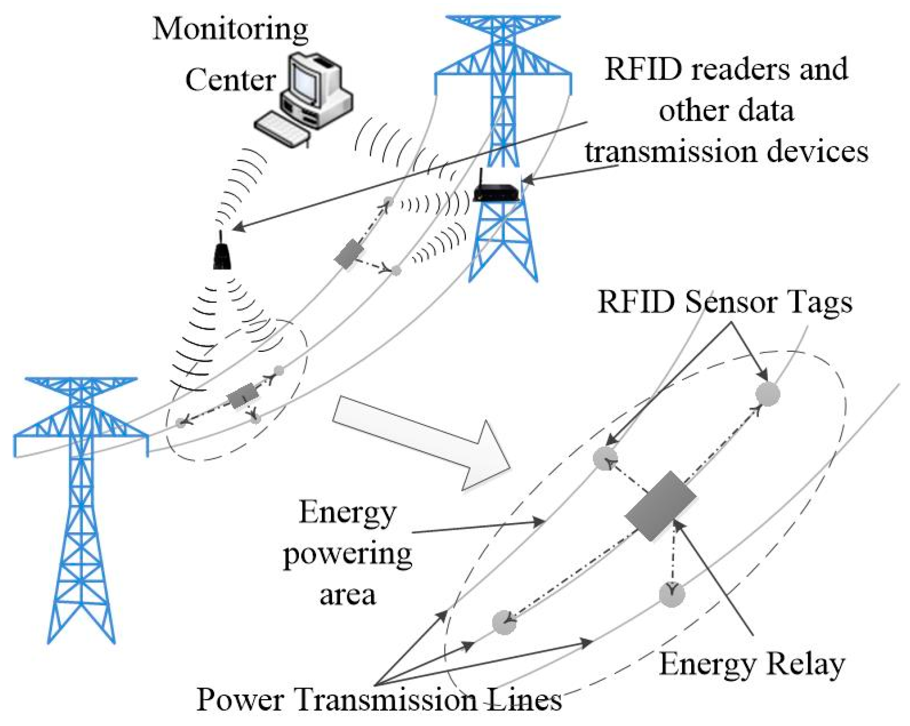
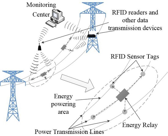
2.2. Principle of RFID-Based Monitoring Networks

Figure 1 sketches the basic idea of the relay-powered RFID monitoring networks, consisting of several RFID sensor tags and data communication devices. Relays are used to obtain energy from electric fields and radiate RF energy to power the RFID sensor tags, which are incorporated with various sensors to monitor the environment. The measurement data is read by RFID readers operated at a safe distance and uploaded to the monitoring center with the communication devices like SCADA Remote Terminal Units or mobile base stations.
Figure 2 shows the structure of the passive RFID sensor tag for application on transmission lines. In order to realize online monitoring, the RFID sensor tag is equipped with two antennas for energy harvesting and ultra high frequency communicating respectively. The energy harvester, composed of the energy harvester antenna, a matching network, and a RF-DC rectifier, can transfer the received RF energy to a stable DC voltage supply for the passive RFID sensor tag [28,29].

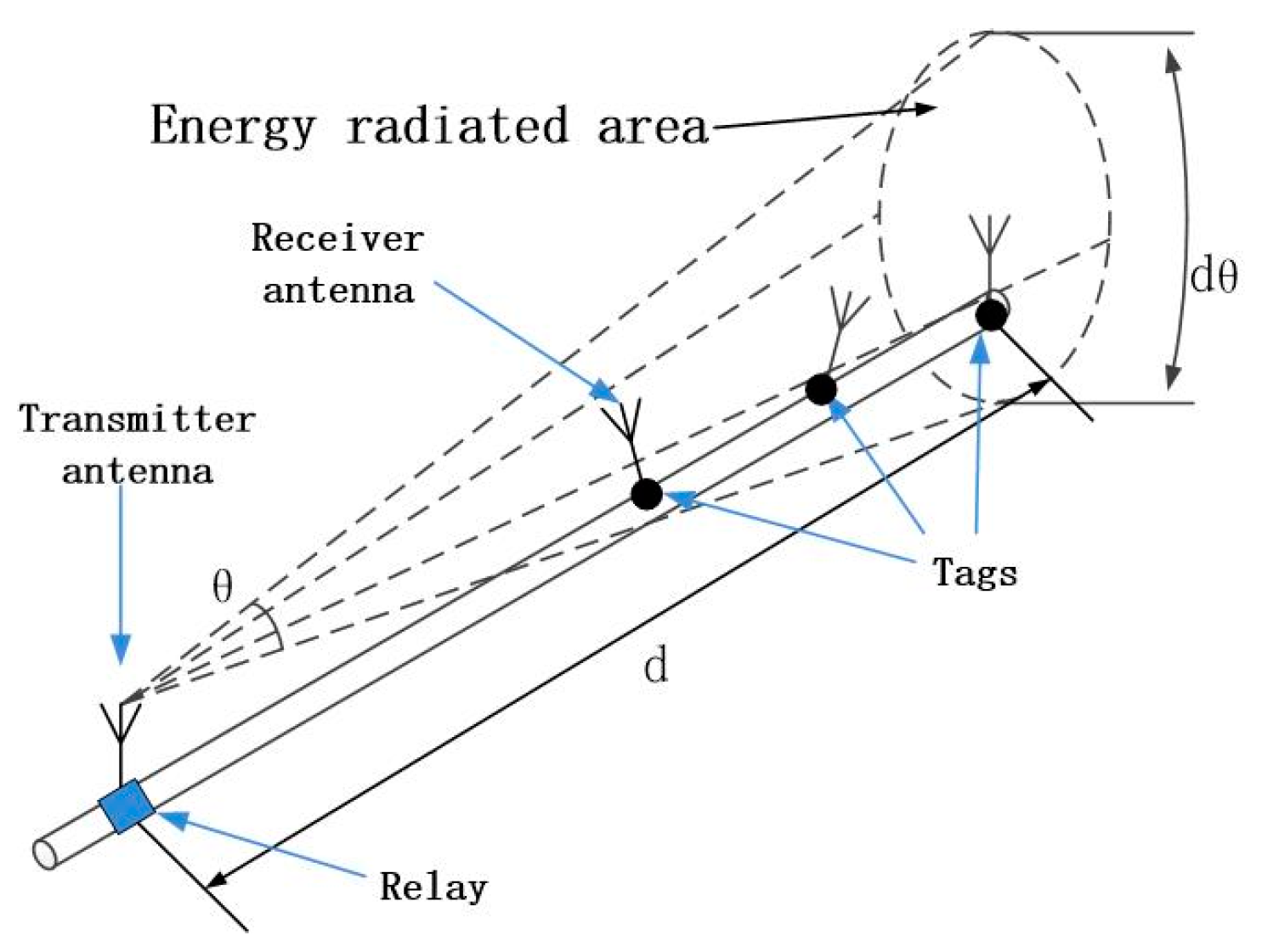
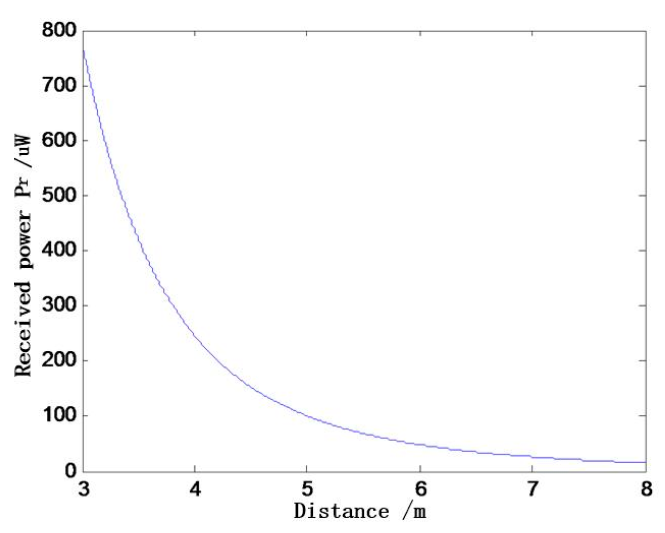
2.3. Model of RF Wave Transmission

The RF energy transmission model can be equal to a free space propagation model because of the lack of obstacles around the proposed relay. The energy transmission is susceptible to ambient environmental factors like wind, rain and electromagnetic. In this paper, the rain fade can be ignored, because the wavelength of RF waves (about 69 cm for a 433 MHz wave) is much longer than the diameter of the raindrop (less than 0.6 cm). Also, rain mainly influences extra-long communication over thousands of meters, while our energy transmission range is less than 10 m [30,31]. Hence the main factors need to be considered are the influences of the electromagnetic environment and wind swing.
The basic model of wave transmission on power lines is shown in Figure 3. The relay radiates a conical beam and the radiating area St can be expressed as:
S t = π d 2 θ 2 4
where d is the distance between the relay and the tags, θ is the vertical beamwidth of transmitter antenna. The RF energy is mainly transmitted in the Fresnel Zone and the power line will not cause any loss because of the astatic reflector of its rough surface. The energy loss mainly results from the line-of-sight transmission loss, so the received power Pr in the radiated area can be expressed as [32]:
P r = P t G t G r λ 2 ( 4 π ) 2 d 2 L
where Pt is the transmitted power of the relay, Gt is the antenna gain of the transmitter, Gr is the antenna gain of the receiver, d is the distance between the relay to receiver, λ is the wavelength of the radiated wave, L is the loss of hardware which is independent with the transmission process. If ignoring the effect of hardware (L = 1) and taking dB as the unit, Pr can be described by the following equation:
P r = P t + 10 [ log G t + log G r ]
Assuming that energy is distributed averagely in the radiating area, the received energy from the tags’ antenna Pra can be described as:
P r a = A r S t P r = 4 A r π d 2 θ 2 P r
where Ar is the active area of the receiver antenna.
When the radiated energy in 433 MHz is 30 dBm, Gt = 12 dBi, Gr = 1 dBi, θ = 10°, the MATLAB simulation results of the relationship between the received power and transmission distance are shown in Figure 4. The received power reduced quickly with the increasing of transmitting distance within the range from 3 to 8 m. The simulated Pra is 26.29 μW at the distance of 7 m, which is still larger than the typical minimum operating power (20 μW) of an RFID sensor tag [23].

2.4. Influence of Electromagnetism

The electromagnetic compatibility (EMC) has been analyzed and verified in [7]. By using a metal case, the electromagnetic influence has been greatly reduced, and the case does not decrease but rather increases the radiated power due to the enlarged active area of the antenna. Furthermore, the metal case can offer the inside electrical components excellent protection from EMC disturbances [7].

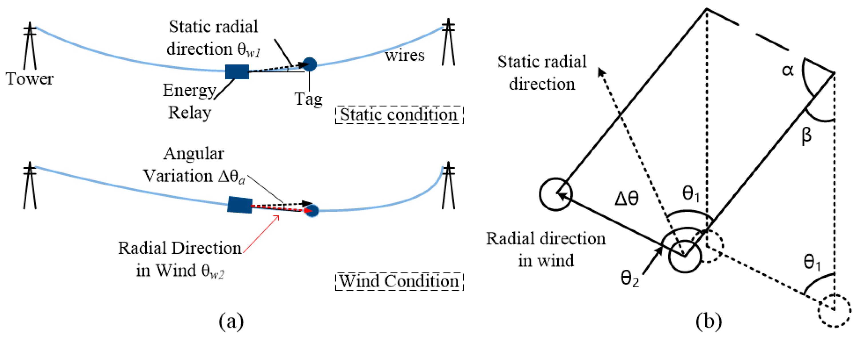
2.5. Influence of Wind

Figure 5a shows the wind influence of the same line energy transmission between the relay and the tags. Curvature change in the wire will change the relative position of the relay and the tags. In the vertical direction, the relative height between the relay and the tags changes little because a wire with a low elastic coefficient is settled on the transmission tower. Along the wire direction, θw1 is the static radial direction, θw2 is the radial direction in wind, and the angular variation Δθa results from the change of straight-line distance from the relay to tags and the sag of the wire. Actually, the straight-line distance of energy transmission is less than 10 m, and much shorter than the span length between two towers (over 300 m), hence the angular variation caused by the curvature change can be ignored. Based on the above analysis, a high-gain, narrow-beam, directional antenna can be used in the energy transmission over the same wire to enhance the density of radiated energy.
Figure 5b shows the cross-section view of energy transmission between two lines. Assuming that two wires are in the same amplitude, the dotted lines represent the static position of the antennas and the full lines represent the maximum deviating position of the antenna in wind. The angular variation of the two radial directions Δθ can be expressed as:
Δ θ = θ 2 θ 1 = ( π α ) ( π ( α + β ) ) = β
where β is the angle of wind deflection, θ1 is the angle between the radial direction and vertical direction without wind, and θ2 is the angle between the radial direction and vertical direction with the maximum wind. Therefore, the beamwidth of the radiating antenna should be larger than double of the maximum swing angle βmax.
The swing angle β can be described as:
β = arctan g 4 g 1
where g1 is the wire gravity load per unit area as shown in Equation (7), and g4 is the wind load per unit area, as shown in Equation (8):
g 1 = W 0 g S × 10 3
where W0 is the weight of the wire, S is the sectional area of the wire, and g is gravitational acceleration.
g 4 = α K v w 2 d 16 S g × 10 3 M P a / m
where α is uneven factor of wind velocity, K is the factor of wire size, vw is wind velocity, d is the external diameter of the wire. Based on the Equations (6)–(8), β can be described as:
β = arctan g 4 g 1 = arctan α K v w 2 d 16 W 0
Based on “code for designing of 110–750 kv overhead transmission line” (GB50545-2010) [31], the maximum design wind velocity (vw,max) of the wire which installed over 10 m high should not lower than 26.85 m/s. When the wind velocity is 26.85 m/s (vw = vw,max), α = 0.61, using LGJ-240/40 as the wire, d = 21.66 mm, S = 277.75 mm2, K = 1.05, W0 = 964.3 kg/km, the maximum swing angle βmax can be calculated as 32.95 based on Equation (9).
Based on the analysis above, the beamwidth of radiating antenna should be over 65.90° (2 βmax). However, adopting wide-angle antennas will decrease the density of radiated energy, so we add bearings as the supporting structures of the relay, ensuring the antenna to radiate in a stable direction due to the gravity of the relay.

3. Prototype Design

Figure 6a shows the structure of energy harvester, which is mainly constructed with an aluminum-made tube. The surface of the tube is polished in order to avoid partial discharge and corona. The tube is installed on the wire with the supporting insulators and bearings to obtain energy from the time-varying electric field. r1 is the radius of the wire, r2 is the radius of the tube, l is the length of the tube, d is the distance from the tube to the ground. C1 is the capacitance of the tube-formed capacitor, and C2 is the earth capacitance of the tube.
Figure 6b shows the architecture of the relay. The relay consists of the energy harvesting tube, a voltage conversion circuit and an energy transmitter. The voltage conversion circuit is used to provide a stable continuous energy to charge the ultra-capacitor Cu, Cu is used to store energy and power the transmitter continuously, and the transmitter is used to radiate energy with RF waves through the transmitter antenna.

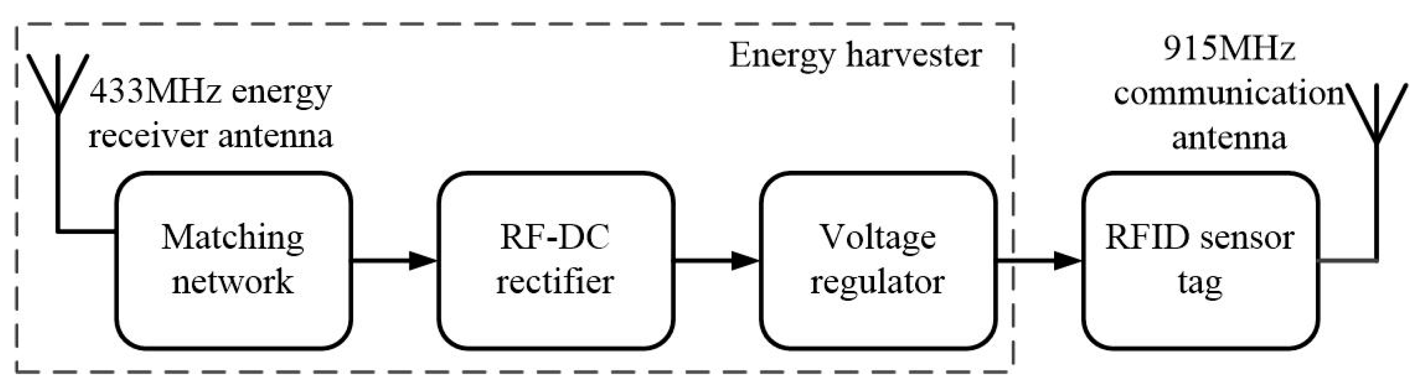
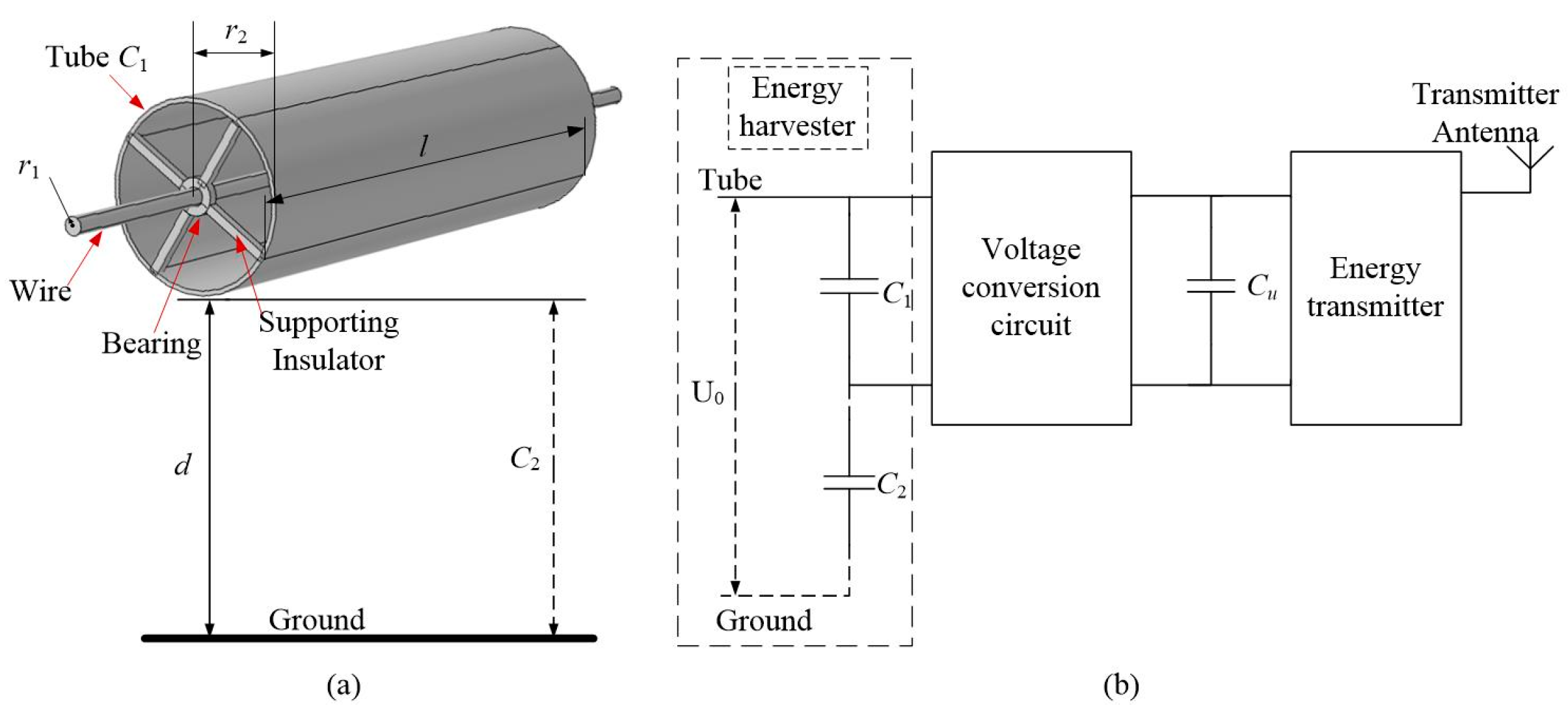
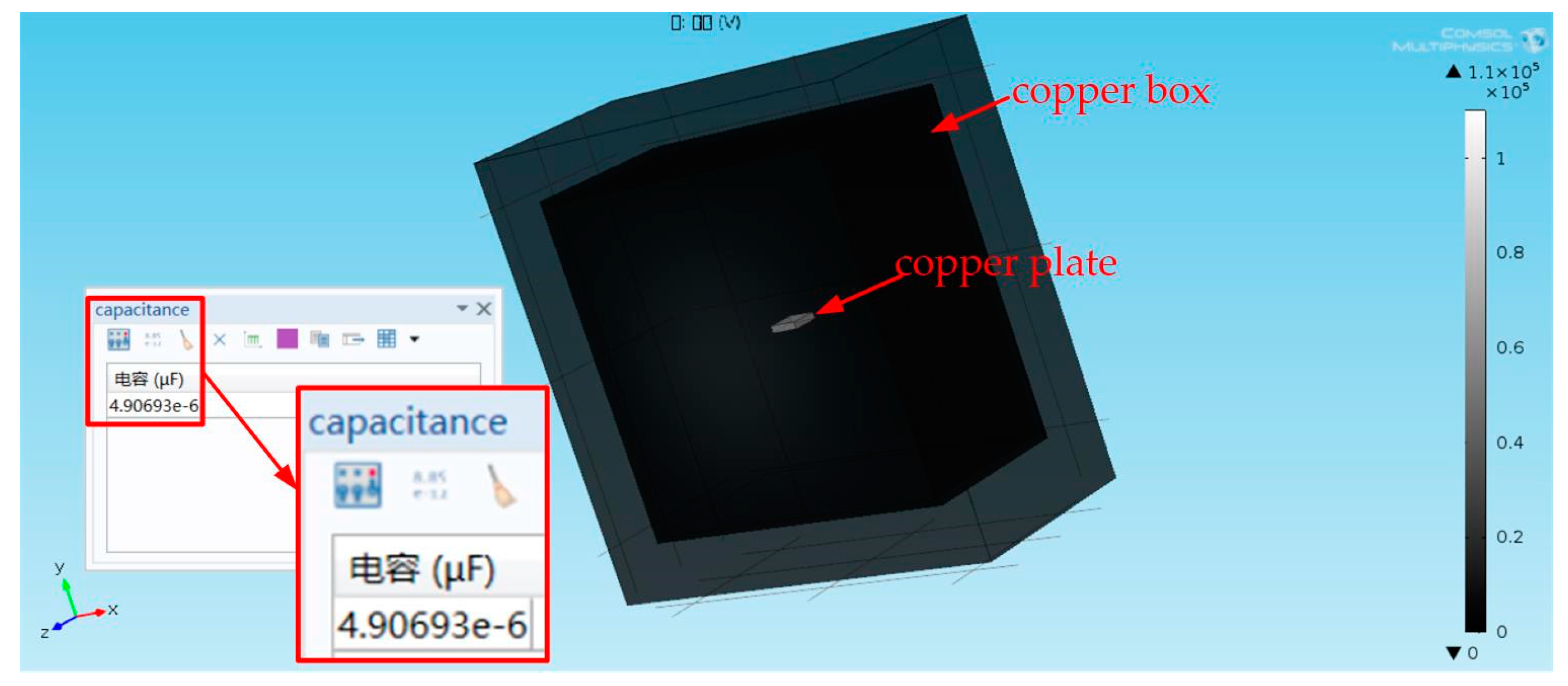
3.1. Energy Harvester on 110 kv Lines

The energy tube with a radius of 10 cm and a length of 60 cm can be equal to a floating capacitor. The capacitance of the tube C1 is given by
C 1 = 2 π ε 0 ε l ln ( r 2 / r 1 )
where l is the length of the tube, r2 is radius of the tube, ε0 is dielectric constant between tube and wire, and ε0 is the relative dielectric constant of air. Assuming that the wire is installed at a height of 10 m above the ground (d = 10 m), the earth capacitance of the tube C2 is express as:
C 2 = 2 π ε 0 l cosh 1 ( d / r 2 )
Because d is much larger than r2, the voltage V harvested from the tube can be described as:
V = C 2 C 1 + C 2 V 0 = C 2 C 1 + C 2 V a c 2 sin ( ω t )
where V0 is the real-time voltage of the wire, Vac is the voltage effective value of the wire. On a 110 kv line, assuming that r1 = 0.01083 m, r2 = 0.1 m, ε = 1, l = 0.6 m, d = 10 m the voltage V of the tube is 33.32 kv.
When the relay is installed at a height of 10 m above the ground, C2 can be calculated to be 4.69 pF according to Equation (11). However, it is hard to test a harvester over 10 m high in laboratory, so we designed a capacitor composed of a copper box and a small copper plate to simulate the earth capacitance. The COMSOL Multiphysics simulation of the self-made capacitor is shown in Figure 7. The size of the copper box is 1 m × 0.5 m × 1 m, the thickness of the box shell is 0.02 m and the size of the plate is 85 mm × 85 mm × 20 mm. When the plate is placed at the center of the box, the simulated capacitance is 4.90693 pF.

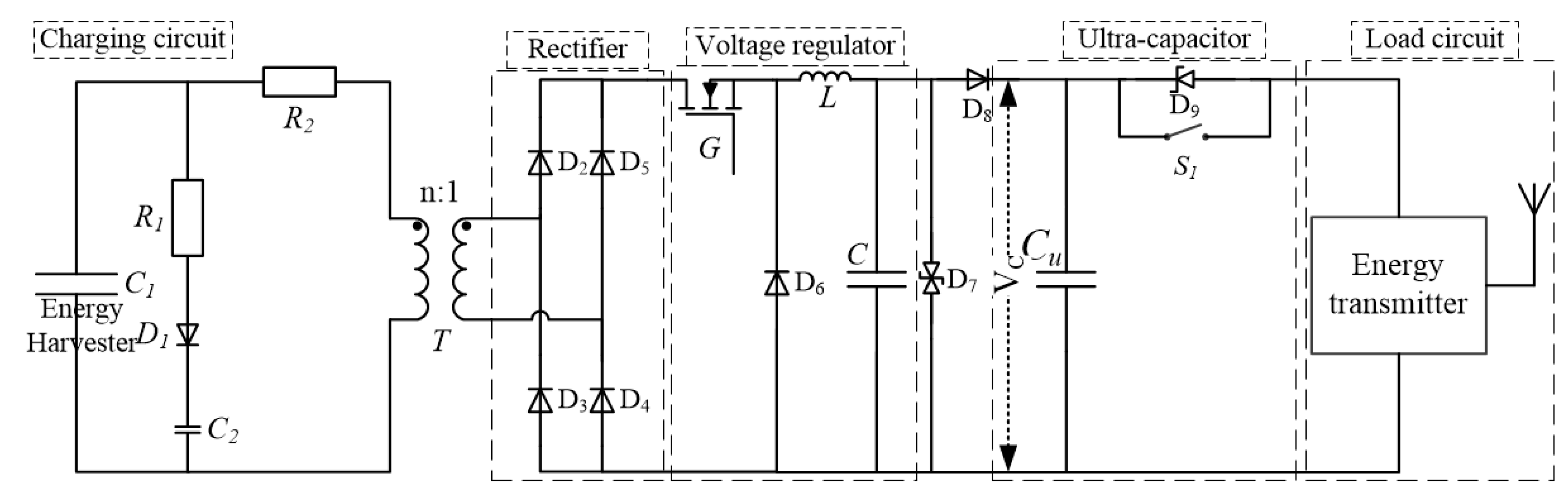
3.2. Voltage Conversion Circuit

As shown in Figure 8, the voltage conversion circuit contains a high-voltage potential transformer (T), a rectifier, a voltage regulator and an ultra-capacitor Cu. The primary side of the transformer connects the tube with the wire, and the secondary side is connected to the rectifier. A large-resistance resistor R2 is used to decrease the high voltage on the primary side of the potential transformer. The capacitor C2 and the primary coil of transformer compose a low pass filter to filter high frequency and high voltage pulse current. The resistor R1 and diode D1 are used to eliminate the mal-operation. The diodes D2D5 compose the rectifier, a buck circuit consists of the voltage regulator with a giant transistor G, an inductor L and a capacitor C. A clamping diode (D7) is used as an overvoltage protection of 5 v. The ultra-capacitor Cu not only stores energy to cope with the power outage, but also regulates the output voltage. D9 is a voltage-regulator diode operating under reverse breakdown state to ensure the ultra-capacitor charged well. The switch S1 will be closed to power the energy transmitter when the power outage happens.
When designed for a 110 kv line, the peak voltage on C1 can be calculated as 47.13 kv based on the Equation (12), and its effective value of voltage is 33.32 kv. Thus, we choose a 4 MΩ resistor (R2) and a high-voltage potential transformer (T) with the 1000:5 transformation ratio. When charging load Z is 1 Ω, L = 0.9 mH, C = 72 uF, the Multisim simulation results are shown in Figure 9, and the charging voltage Vc of ultra-capacitor is 4.7 v.

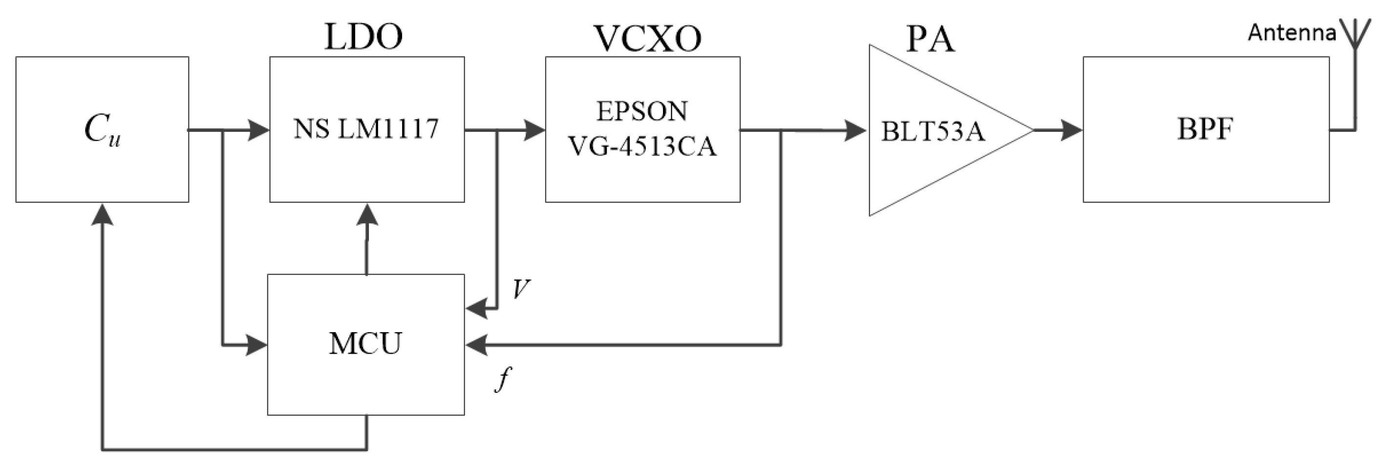
3.3. Energy Transmitter

Differed from the traditional radio communication [33,34], the design of our wireless power transmitter is not necessary to consider the influence of noise. Figure 10 shows the structure of energy transmitter. The ultra-capacitor Cu works as the energy supply for the entire circuit. A Microprogrammed Control Unit (MCU) is used to stabilize the output frequency and deal with the influences from outside, like the power outage. When a power outage happens, the MCU can stabilize the output of Cu to ensure the energy supply as well as the frequency of radiated waves for three minutes. A voltage-controlled crystal oscillater (VCXO)—VG-4513CA (EPSON, Nagano-ken, Japan) is used to provide a stable RF signal of 433 MHz. A low dropout regulator (LDO)—LM1117T-ADJ (National Semiconductor, Santa Clara, CA, USA), controlled by MCU, is responsible for adjusting the control voltage of VCXO. Some feedback from the output end of the LDO and the VCXO are connected to MCU. The waves are enhanced by a power amplifier (PA) (BLT53A), and then filtered and radiated by a band-pass filter and an antenna. A small, light microstrip antenna is chosen as the transmitter antenna, because it can be easily installed in the tube to insulate from the strong electromagnetic environment.

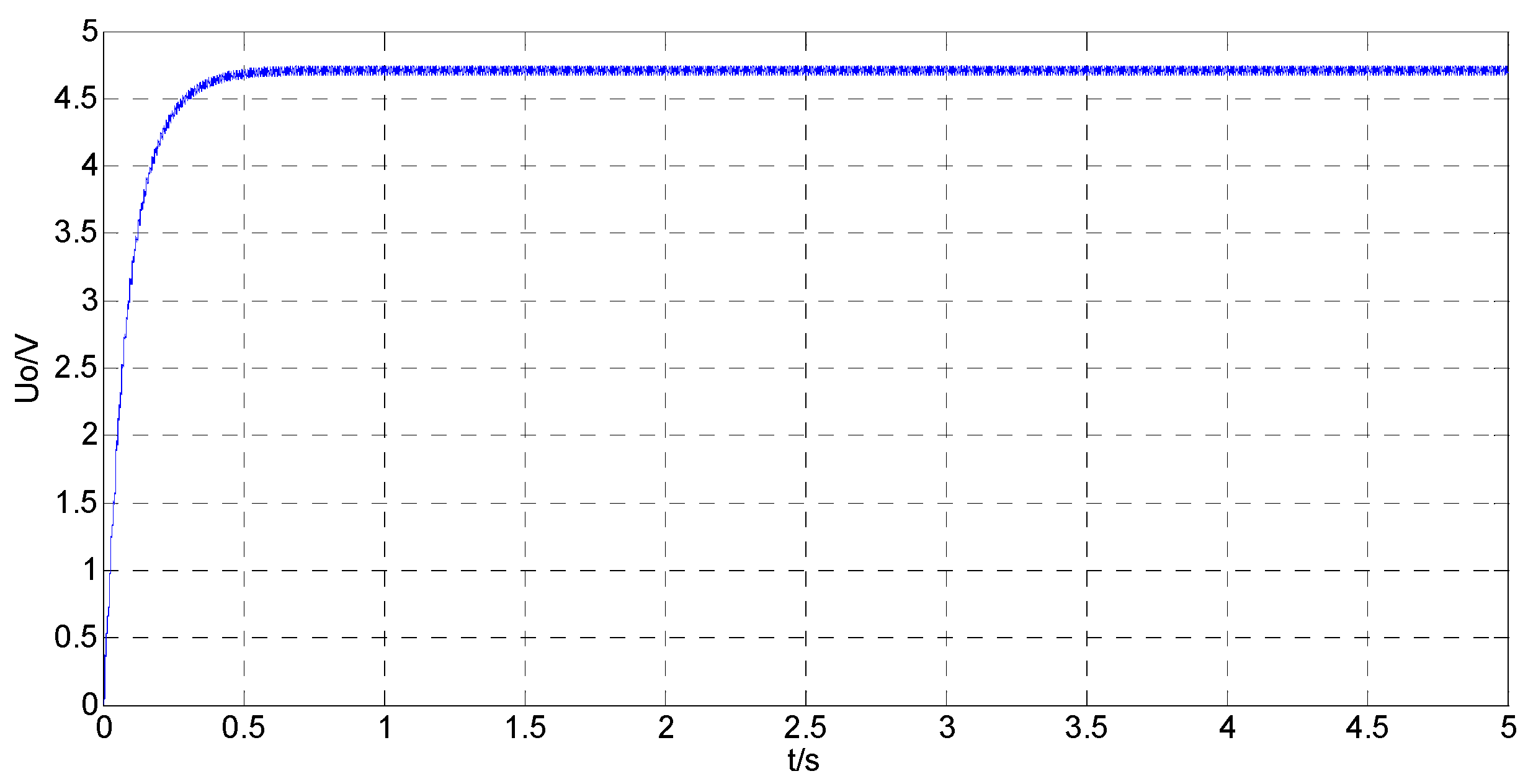
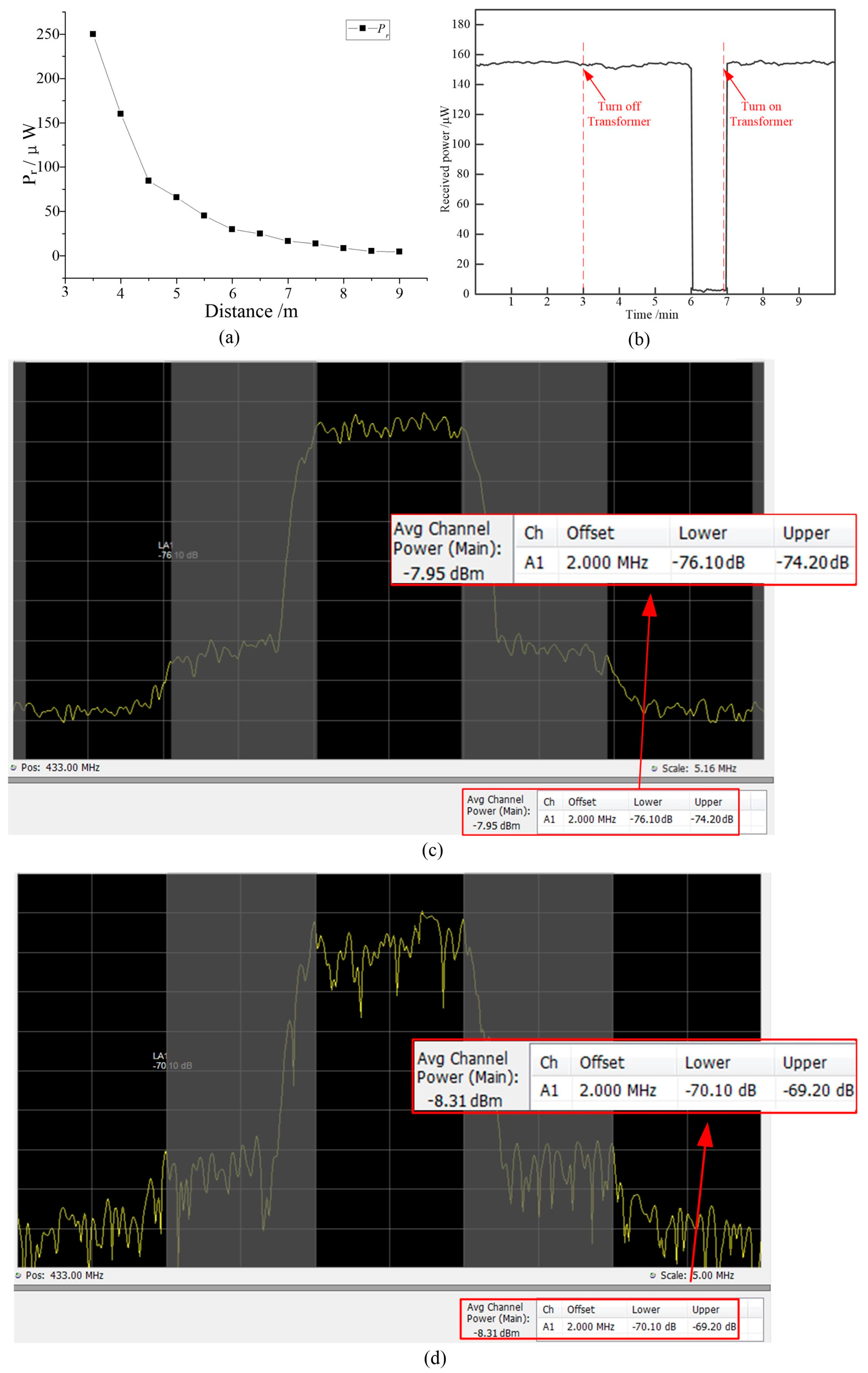
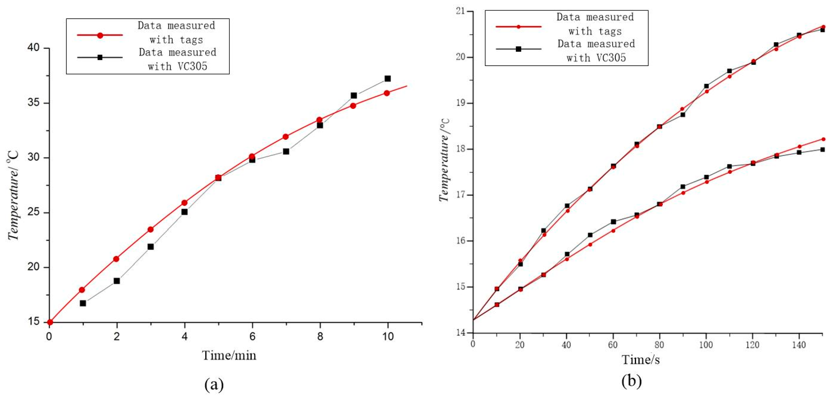
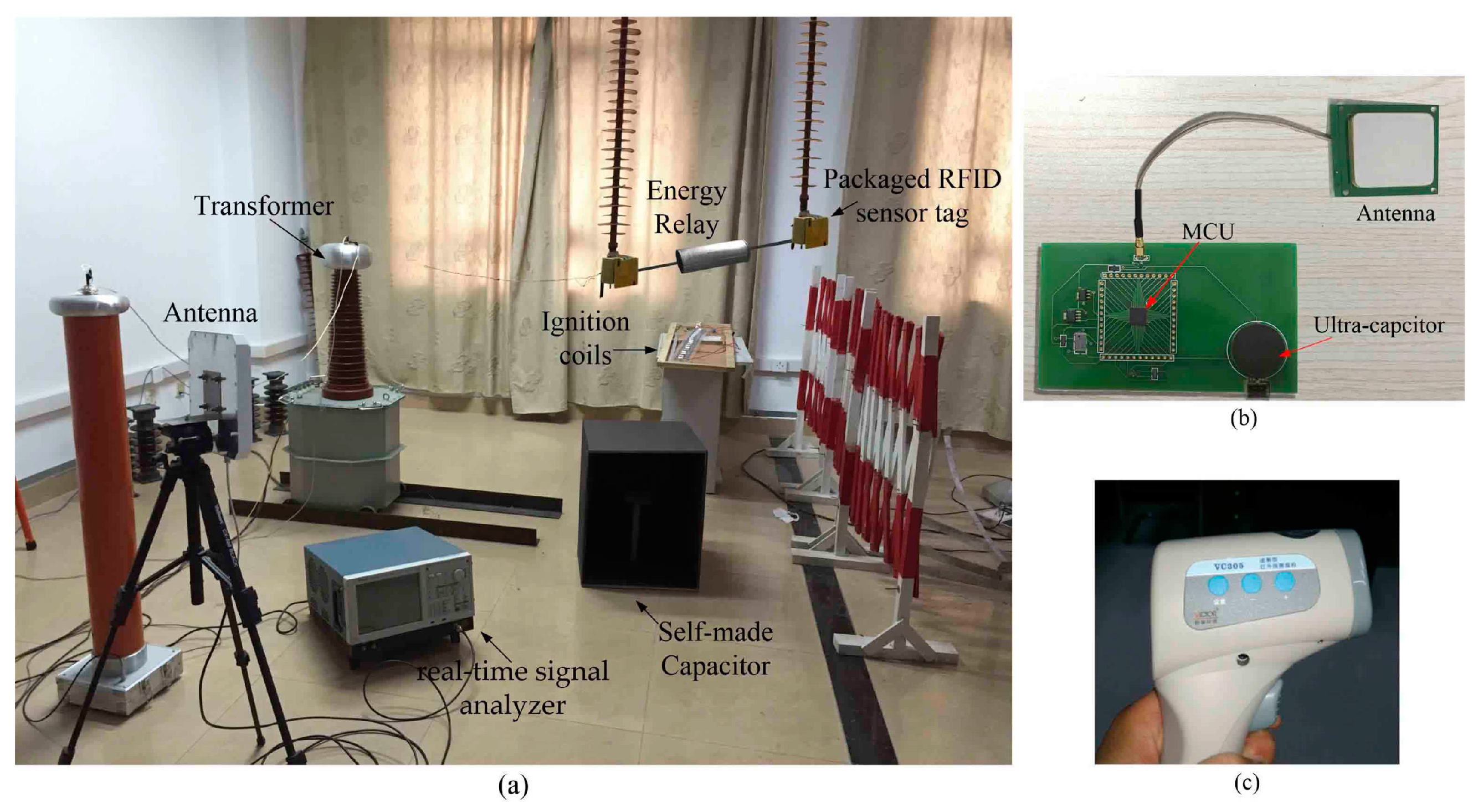
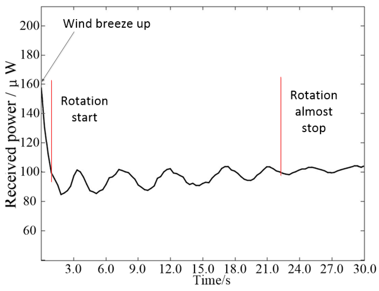
4. Experiment and Results

Figure 11a shows the testing environment for the proposed relay. The relay is installed on a steel-cored aluminium strand wire (LGJ-240/40) and the design of our RFID temperature sensor tag is from the reference [31]. The 110 kv voltage is provided by a 110 kv transformer. The energy is received by a 20 cm × 20 cm antenna and analyzed by a real-time signal analyzer—RSA5115B (Tektronix, Johnston, SC, USA). The antenna is located 4 m away from the relay when testing the influences of noise, power outage and wind. Several ignition coils connected with high-voltage sources are used to generate the spark discharge, which is the main cause of the noise on transmission lines. The overall weight of the proposed relay is 2.79 kg, which is less than the maximum load permitted on the power transmission line [30]. The photo of the energy transmitter and the far-infrared temperature instrument (Victor (Xi’an, China) VC305) is shown in Figure 11b,c respectively.
Figure 12a shows the measurement results of the channel power at different measuring distances. The measured channel power at the distance of 6m is 26.92 μW (−1.57 dBm), which is higher than the typical minimum operating power of an RFID tag [23]. Figure 12b shows results of the channel power when testing the power outage influence. We simulated the power outage at the 3rd min and then restored the power at the 7th min. The results prove that the relay can continue operation for 3 min after the power outage, and can quickly recover within 5 s after the power is restored.
When testing the influence of noise, the receive antenna is placed 4m away from the relay. Figure 12c shows the measured channel power is −7.95 dBm. As shown in Figure 12d, we measured the channel power again when spark discharges were generated, the measured channel power is −8.31 dBm. Comparing these two results, we can conclude that the channel power is reduced by an acceptable 7.74% during spark discharge.
When testing the influence of the wind, four blowers are used to provide various wind velocities. Figure 13 shows the harvested energy from the receiving antenna. The energy transmission has an excellent stability under wind and the maximum measured error of the channel power is less than 15.31%. Also, it proves that the energy loss mainly results from the position change of the relay: when the relay rotates slightly, the received energy tends to be stable.
Figure 14 compares the measurement results from the sensor tag and the far-infrared temperature instrument respectively. The RFID reader was placed 6 m away from the relay to read the measurement data. Figure 14a shows the results of temperature rise without wind and Figure 14b shows the results when the velocity of wind is 2.9 m/s and 6.2 m/s respectively. The results measured by the tag and the VC305 show an excellent consistency, and the maximum measured error is less than 4.4%. Powered by the proposed relay, the RFID sensor tag can operate at a maximum distance of 18 m away from the RFID reader, which is much larger than the required safe distance of 3 m in a power system [31].

5. Conclusions

In this paper, a novel energy relay is proposed to provide a power source for RFID sensor tags on power transmission lines. The design of the relay is based on an analysis of the environmental factors affecting power lines, including rain, high electromagnetism and wind. A prototype of the relay for 110 kv lines was built and tested in laboratory. The test results show that 26.92 μW of energy can be received at a distance of 6 m, which is enough to support an RFID sensor tag. There is little influence on the transmission of energy from wind, noise or power outage. The results also show that the proposed relay not only prolongs the operation life of the sensors, but also saves on maintenance costs. In future, we plan to optimize the circuits and antennas to improve the radiated power density and apply our design for higher voltage lines as well as bundle conductors.

Acknowledgments

This work was supported by the National Natural Science Funds of China under Grant No. 51577046, the National Defense Advanced Research Project under Grant No. C1120110004, 9140A27020211DZ5102, the National Natural Science Foundation of China under Grant No. 61501162, the Key Grant Project of Chinese Ministry of Education under Grant No. 313018, Anhui Provincial Science and Technology Foundation of China under Grant No. 1301022036, Science and technology support project of Jiangxi Province under Grant No. 20161BBE50076.

Author Contributions

Jin Tong conceived, designed and performed the experiments; Yigang He provided the instructions for the design and financial support for this research; Bing Li helped to perform the measurements; Tao Wang helped to analyze the data; Jin Tong wrote the paper; and Fangming Deng provided help with revision of this manuscript.

Conflicts of Interest

The authors declare no conflict of interest.

Abbreviations

The following abbreviations are used in this manuscript:
RFIDRadio Frequency Identification Devices
RFRadio frequency
EMCElectromagnetic compatibility

References

  1. Sheng, Q.Y.; Li, J.; Xu, T.Y. Study on the monitoring technology for overhead transmission line icing. In Proceedings of the 2011 IEEE Power Engineering and Automation Conference (PEAM), Wuhan, China, 8–9 September 2011; pp. 168–171.
  2. Guo, Z.; Ye, F.; Guo, J.; Liang, Y.; Xu, G.; Zhang, X.; Qian, Y. A wireless sensor network for monitoring smart grid transmission lines. In Proceedings of the 2014 23rd International Conference on IEEE Computer Communication and Networks (ICCCN), Shanghai, China, 4–7 August 2014; pp. 1–6.
  3. Sun, X.; Lui, K.S.; Wong, K.K.; Lee, W.K.; Hou, Y.; Huang, Q.; Pong, P.W. Novel application of magnetoresistive sensors for high-voltage transmission-line monitoring. IEEE Trans. Magnet. 2011, 47, 2608–2611. [Google Scholar] [CrossRef] [Green Version]
  4. Zhou, G.; Huang, L.; Li, W.; Zhu, Z. Harvesting ambient environmental energy for wireless sensor networks: A survey. J. Sens. 2014, 2014, 1–20. [Google Scholar] [CrossRef]
  5. Moghe, R.; Lambert, F.C.; Divan, D. Smart “stick-on” sensors for the smart grid. IEEE Trans. Smart Grid 2012, 3, 241–252. [Google Scholar] [CrossRef]
  6. Hill, C.A.; Such, M.C.; Chen, D.; Gonzalez, J.; Grady, W.M. Battery energy storage for enabling integration of distributed solar power generation. IEEE Trans. Smart Grid 2012, 3, 850–857. [Google Scholar] [CrossRef]
  7. Zangl, H.; Bretterklieber, T.; Brasseur, G. A feasibility study on autonomous online condition monitoring of high-voltage overhead power lines. IEEE Trans. Instrum. Meas. 2009, 58, 1789–1796. [Google Scholar] [CrossRef]
  8. Wu, Z.; Wen, Y.; Li, P. A Power supply of self-powered online monitoring systems for power cords. IEEE Trans. Energy Convers. 2013, 28, 921–928. [Google Scholar] [CrossRef]
  9. Tan, Y.K.; Hoe, K.Y.; Panda, S.K. Energy harvesting using piezoelectric igniter for self-powered radio frequency (RF) wireless sensors. In Proceedings of the IEEE International Conference on Industrial Technology (ICIT), Mumbai, India, 15–17 December 2006; pp. 1711–1716.
  10. Washiro, T. Applications of RFID over power line for Smart Grid. In Proceedings of the 16th IEEE International Symposium on Power Line Communications and Its Applications (ISPLC), Beijing, China, 27–30 March 2012; pp. 83–87.
  11. Vaidya, B.; Makrakis, D.; Mouftah, H.T. Authentication mechanism for mobile RFID based Smart grid network. In Proceedings of the 2014 IEEE 27th Canadian Conference on Electrical and Computer Engineering (CCECE), Toronto, ON, Canada, 4–7 May 2014; pp. 1–6.
  12. Huettner, J.; Kurz, F.; Metz, G.; Ziroff, A. Lightweight power line communications for Smart Grid applications with standard RFID tags. In Proceedings of the IEEE Global Communications Conference (GLOBECOM), Anaheim, CA, USA, 3–7 December 2012; pp. 3165–3170.
  13. Kang, S.H.; Kim, Y.H.; Lee, E.J.; Lee, S.G.; Min, B.C.; An, J.; Kim, D.H. Implementation of Smart Floor for multi-robot system. In Proceedings of the 2011 5th International Conference on Automation, Robotics and Applications (ICARA), Wellington, New Zealand, 6–8 December 2011; pp. 46–51.
  14. Sabesan, S.; Crisp, M.J.; Penty, R.V.; White, I.H. Wide area passive UHF RFID system using antenna diversity combined with phase and frequency hopping. IEEE Trans. Antennas Propag. 2014, 62, 878–888. [Google Scholar] [CrossRef]
  15. Cho, H.; Kim, J.; Baek, Y. Large-scale active RFID system utilizing ZigBee networks. IEEE Trans. Consum. Electron. 2011, 57, 379–385. [Google Scholar] [CrossRef]
  16. Peng, Q.; Zhang, C.; Zhao, X.; Sun, X.; Li, F.; Chen, H.; Wang, Z. A low-cost UHF RFID system with OCA tag for short-range communication. IEEE Trans. Ind. Electron. 2015, 62, 4455–4465. [Google Scholar] [CrossRef]
  17. Cheng, X.; Lu, J.; Cheng, W. A Survey on RFID Applications in Vehicle Networks. In Proceedings of the 2015 International Conference on Identification, Information, and Knowledge in the Internet of Things, Beijing, China, 22–23 October 2015; pp. 146–151.
  18. Catarinucci, L.; Colella, R.; Esposito, A.; Tarricone, L.; Zappatore, M. RFID sensor-tags feeding a context-aware rule-based healthcare monitoring system. J. Med. Syst. 2012, 36, 3435–3449. [Google Scholar] [CrossRef] [PubMed]
  19. Ashidate, S.I.; Murashima, S.; Fujii, N. Development of a helicopter-mounted eye-safe laser radar system for distance measurement between power transmission lines and nearby trees. IEEE Trans. Power Deliv. 2002, 17, 644–648. [Google Scholar] [CrossRef]
  20. Catarinucci, L.; Colella, R.; de Donno, D.; Tarricone, L. RFID augmented devices for autonomous sensing and computation. In Proceedings of the 2013 European Microwave Conference (EuMC), Nuremberg, Germany, 6–10 October 2013; pp. 999–1002.
  21. Yang, P.; Wu, W.; Moniri, M.; Chibelushi, C.C. Efficient object localization using sparsely distributed passive RFID tags. IEEE Trans. Ind. Electron. 2013, 60, 5914–5924. [Google Scholar] [CrossRef]
  22. Deng, F.; He, Y.; Li, B.; Zuo, L.; Wu, X.; Fu, Z. A CMOS pressure sensor tag chip for passive wireless applications. Sensors 2015, 15, 6872–6884. [Google Scholar] [CrossRef] [PubMed]
  23. Deng, F.; He, Y.; Zhang, C.; Feng, W. A CMOS humidity sensor for passive RFID, sensing applications. Sensors 2014, 14, 8728–8739. [Google Scholar] [CrossRef] [PubMed]
  24. Deng, F.; He, Y.; Li, B.; Zhang, L.; Wu, X.; Fu, Z.; Zuo, L. Design of an embedded CMOS temperature sensor for passive RFID tag chips. Sensors 2015, 15, 11442–11453. [Google Scholar] [CrossRef] [PubMed]
  25. Okrainskaya, I.S.; Sidorov, A.I.; Gladyshev, S.P. Electromagnetic environment under over head power transmission lines 110–500 kV. In Proceedings of the 2012 International Symposium on Power Electronics, Electrical Drives, Automation and Motion (SPEEDAM), Sorrento, Italy, 20–22 June 2012; pp. 796–801.
  26. Choi, J.; Cho, J.K.; Seo, C. Analysis on transmission efficiency of wireless energy transmission resonator based on magnetic resonance. In Proceedings of the 2011 IEEE MTT-S International Microwave Workshop Series on Innovative Wireless Power Transmission: Technologies, Systems, and Applications (IMWS), Uji, Japan, 12–13 May 2011; pp. 199–202.
  27. Pescovitz, D. The power of small tech. In Proceedings of the Colloquium on Structural Information & Communication Complexity, Andros, Greece, 10–12 June 2002; Volume 127, pp. 173–184.
  28. De Donno, D.; Colella, R.; Tarricone, L.; Catarinucci, L. Novel fully-passive multifunction RFID-enabled devices. In Proceedings of the IEEE Microwave Conference, Rome, Italy, 6–9 October 2014; pp. 271–274.
  29. De Donno, D.; Catarinucci, L.; Tarricone, L. RAMSES: RFID augmented module for smart environmental sensing. IEEE Trans. Instrum. Meas. 2014, 63, 1701–1708. [Google Scholar] [CrossRef]
  30. Fiebig, U.C. Modeling rain fading in satellite communications links. In Proceedings of the Vehicular Technology IEEE Conference, Houston, TX, USA, 16–20 May 1999; Volume 3, pp. 1422–1426.
  31. Meng, Y.S.; Lee, Y.H.; Ng, B.C. The effects of tropical weather on radio-wave propagation over foliage channel. IEEE Trans. Veh. Technol. 2009, 58, 4023–4030. [Google Scholar] [CrossRef]
  32. Ministry of Housing and Urban-Rural Development of the People’s Republic of China. General Administration of Quality Supervision, Inspection and Quarantine. Code for Designing of 110~750 kV Overhead Transmission Line; Standard GB50545-2010; China Planning Press: Beijing, China, 2010. (In Chinese)
  33. Uenishi, K.; Araki, K.; Ishii, H. Transmitter multiplexing system in UHF mobile radio. IEEE Trans. Veh. Technol. 1969, 18, 1–11. [Google Scholar] [CrossRef]
  34. Alvarez, J.; Chiodo, R.; McDaniel, L.; van Rheeden, D. Frequency and waveform agile receiver covering the ultra high frequency band. In Proceedings of the Aerospace IEEE Conference, Big Sky, MT, USA, 1–8 March 2014; pp. 1–8.
Figure 1. Principle of the proposed relay-powered radio frequency identification (RFID) monitoring networks on power transmission lines.
Energies 09 00476 g001
Figure 2. Block diagram of double-antenna radio frequency identification (RFID) sensor tag.
Energies 09 00476 g002
Figure 3. Basic model of wave transmission on power line.
Energies 09 00476 g003
Figure 4. Relationship between received power and transmission distance.
Energies 09 00476 g004
Figure 5. Wind influence on energy transmission: (a) Transmission on the same line; (b) Cross section of transmission on different lines.
Energies 09 00476 g005
Figure 6. Prototype of the proposed relay: (a) Structure of energy harvester; (b) Architecture of energy relay.
Energies 09 00476 g006
Figure 7. COMSOL Multiphysics simulation of self-made capacitor.
Energies 09 00476 g007
Figure 8. Voltage conversion Circuit.
Energies 09 00476 g008
Figure 9. Multisim simulation of charging voltage.
Energies 09 00476 g009
Figure 10. Structure of the energy transmitter.
Energies 09 00476 g010
Figure 11. Testing environment: (a) Experimental scene; (b) Photo of the energy transmitter; (c) Far-infrared temperature instrument.
Energies 09 00476 g011
Figure 12. Results of channel power: (a) Measured from different distance; (b) Measured with influence of power outage; (c) Measured without noise; (d) Measured with noise.
Energies 09 00476 g012
Figure 13. Statistical chart of received energy with the wind.
Energies 09 00476 g013
Figure 14. Temperature measurement: (a) Measured without wind; (b) Measured in wind (2.9 m/s, 6.2 m/s).
Energies 09 00476 g014
Table 1. Comparison of different power sources of radio frequency identification (RFID) tags on power lines.
Power SourceAdvantageDisadvantage
Lithium batterySmall, light, high power density, low costCannot work for years without charging [16]
Photovoltaic panelCan work even when power line is turn offNot always available (nights, occlusion with snow etc.), can be destroyed by hail, requires high capacity energy storage [7]
ThermobatteryLight enough to installation, can work under harsh environmentRequires electric current in the conductor, needs radiator [27]
Vibration-power generating batteryCan work even when power line is turn offNot always stable, requires high capacity energy storage, moving parts can hardly be mounted on a power line [9]
Radio frequency (RF) energy powered from relay (This work)Light, have simple circuit architectureNeeds a self-powered relay

