Article

Performance Evaluation of a Helical Coil Heat Exchanger Working under Supercritical Conditions in a Solar Organic Rankine Cycle Installation

1
Department of Flow, Heat and Combustion Mechanics, Ghent University, Sint-Pietersnieuwstraat 41, Ghent 9000, Belgium
2
Department of Natural Resources and Agricultural Engineering, Agricultural University of Athens, Iera Odos street 75, Athens 11855, Greece
*
Author to whom correspondence should be addressed.
Energies 2016, 9(6), 432; https://doi.org/10.3390/en9060432
Submission received: 31 January 2016 / Revised: 4 May 2016 / Accepted: 26 May 2016 / Published: 3 June 2016

Abstract

:
Worldwide interest in low grade heat valorization using organic Rankine cycle (ORC) technologies has increased significantly. A new small-scale ORC with a net capacity of 3 kW was efficiently integrated with a concentrated solar power technology for electricity generation. The excess heat source from Photovoltaic (PV) collectors with a maximum temperature of 100 °C was utilized through a supercritical heat exchanger that uses R-404A as working medium. By ensuring supercritical heat transfer leads to a better thermal match in the heat exchanger and improved overall cycle efficiency. A helical coil heat exchanger was designed by using heat transfer correlations from the literature. These heat transfer correlations were derived for different conditions than ORCs and their estimated uncertainty is ~20%. In order to account for the heat transfer correlation uncertainties this component was oversized by 20%. Next, a prototype was built and installed in an integrated concentrated photovoltaic/thermal (CPV/T)/Rankine system. The results from the measurements show that for better estimation of the sizing of the heat exchanger a more accurate correlation is required in order to design an optimal configuration and thus employ cheaper components.

Graphical Abstract

1. Introduction

An increased demand for energy and environmental issues on a worldwide level have stimulated a number of researchers to work on improving the efficiency of thermodynamic cycles and look for ways of utilizing renewable energy sources. The organic Rankine cycle (ORC) is a suitable technology for employing low grade temperature heat from several renewable energy sources such as biomass, geothermal and solar. Further, the (waste) heat from various processes can be also utilized in such cycles.
For optimal performance of an ORC cycle, a good selection of the working fluid is important and also a proper design and selection of the cycle components is essential. A way to enhance the overall efficiency of an ORC can be achieved by ensuring supercritical heat transfer between the heat source and organic fluid in the heat exchanger [1]. In order to be able to design an optimal heat exchanger suitable to operate at supercritical conditions, proper heat transfer correlations need to be used. Hence, to provide accurate correlations for designing a heat exchanger, the heat transfer process of the working fluids under supercritical conditions has to be studied. At supercritical state there are significant variations of the thermophysical properties such as the specific heat capacity, density, viscosity and thermal conductivity of the fluid. Other important parameters that influence the heat transfer are the working fluid flow direction, tube diameter, heat and mass flux, buoyancy and the type of organic fluid. As the value of the heat transfer coefficient depends on these variations, it is important to study and understand the behaviour of the fluid properties when going from subcritical to supercritical state. Therefore, experimental determination of the local heat transfer coefficients and development of new correlations is under further investigation.
In the second half of the 20th century, a lot of research activities regarding the heat transfer to variety of working fluids such as water, carbon dioxide and helium at the critical and the near-critical region took place. Back in 1957, Bringer and Smith [2] were the pioneers on experimental research on heat transfer to supercritical fluids. Because of the rapid variations of thermal conductivity, viscosity and density they found that the existing empirical and semi-theoretical correlations did not give accurate results. The prompt changes of the thermophysical properties were identified as the main reasons for the deviation between experimental results and predictions by the correlation. Furthermore, some of the first researchers who looked into heat transfer to supercritical water were Dickinson and Weich [3]. A main idea for using supercritical water was for increasing the efficiency of coal fired thermal power plants. The work was followed by Shitsman [4], who did heat transfer research at the near critical region, not only on water but on oxygen and CO2 as well. Krasnoshchekov and Protopopov [5] published a work related to the heat transfer at the supercritical region in tubes for the fluids such as water and CO2. In 1961, Petukhov et al. [6] developed a Nusselt correlation for supercritical CO2 and was the first to take into account the difference in properties between the wall and the bulk temperature of the fluid. This correlation has a correction factor that accounts for the severe thermophysical changes near the pseudo-critical region and is compared in this work with two other correlations. Shitsman [7] published a work related to impairments on heat transfer at supercritical pressure. Bishop et al. [8] investigated the forced convection heat transfer to water at near critical temperatures and supercritical pressure. In 1970, Ackerman [9] investigated the parameters that influence the pseudo-boiling heat transfer of supercritical water in smooth and ribbed tubes. In this period of the 1960s–1970s many heat transfer correlations for supercritical fluids were derived, especially for water. However, for developing these heat transfer correlations the old thermophysical properties of water were used, which were updated and officially adjusted in the 1990s (for example, a peak in the thermal conductivity at critical and pseudo-critical points within a range of pressures from 22.1 MPa to 25 MPa was not officially recognized before the 1990s). Yamagata et al. [10] conducted research related to forced convection heat transfer to supercritical water flowing in vertical tubes. Jackson and Fewster et al. [11] did work on forced convection to supercritical fluids. Most of the experimental investigations were mainly done using vertical positioning of the tubes. In 1964, Vikrev and Lokshin [12] performed one of the earliest studies about supercritical heat transfer to water in horizontal flow in a single tube. This study is of great importance because it was the first attempt to quantitatively formulate the deterioration of the heat transfer when operating in supercritical conditions. Experimental determination of the local heat transfer coefficients when working with organic fluids and in ORC conditions was investigated in a new test set-up. The buoyancy effect on a turbulent and vertical flow was first studied by Jackson and Hall in 1979 [13]. Then there is a gap of some 20 years in the experimental work on supercritical heat transfer, until at the beginning of the 21th century the interest on heat transfer in the supercritical state came to the forefront again. Garimella [14] developed heat transfer correlations for the working fluids R-404A and R-410A and was the first to identify three regions of supercritical heat transfer (liquid-like, pseudo-critical, gas-like region). Recently, Mokry et al. [15] proposed an updated heat transfer correlation based on a new set of heat transfer data by taking into account the latest thermophysical properties of water. These two heat transfer correlations are also used in the current work.
From the literature review by Lazova et al. [16], it can be concluded that there is very limited experimental and heat transfer data at supercritical state for organic fluids used in transcritical ORCs, that is discussed in Section 2.1. The main reason is the difference in the working conditions of an ORC system such as relatively high operational temperature and pressure. This lack of knowledge necessitates the development of new heat transfer correlations suitable for the working fluids used under the supercritical conditions in ORC. Even though the heat transfer correlations mentioned in the text above were derived for operating conditions and fluids (water, CO2 and helium) different from the ones of ORCs, this does not marginalize the importance and the scientific value of the previously performed research.

2. Supercritical Heat Transfer in the Concentrated Photovoltaic/Thermal-Rankine Set-up

Even though the research activities regarding supercritical heat transfer started a long time ago the first published paper found in the literature regarding a supercritical (transcritical) ORC dates from 1981. Haskins [17] performed research activities of a solar receiver coupled to a supercritical ORC engine in order to maximize the thermal efficiency by using toluene as working fluid. Furthermore, ten years later the first paper regarding numerical investigations of forced convective heat transfer to supercritical fluid flow in compact heat exchangers, was published [18]. In 2012, Schuster et al. [19] discussed the influence of the ORC parameters on supercritical plate heat exchangers for such applications. The overall cycle efficiency and the total cost of an ORC system are tightly related with the performance of the heat exchanger. Therefore, an optimal design of this key component is of high importance. It is estimated that the cost of the heat exchangers is usually up to 30% of the total cost of an ORC where evaporator, (regenerator) and condenser are taken into account [20,21].

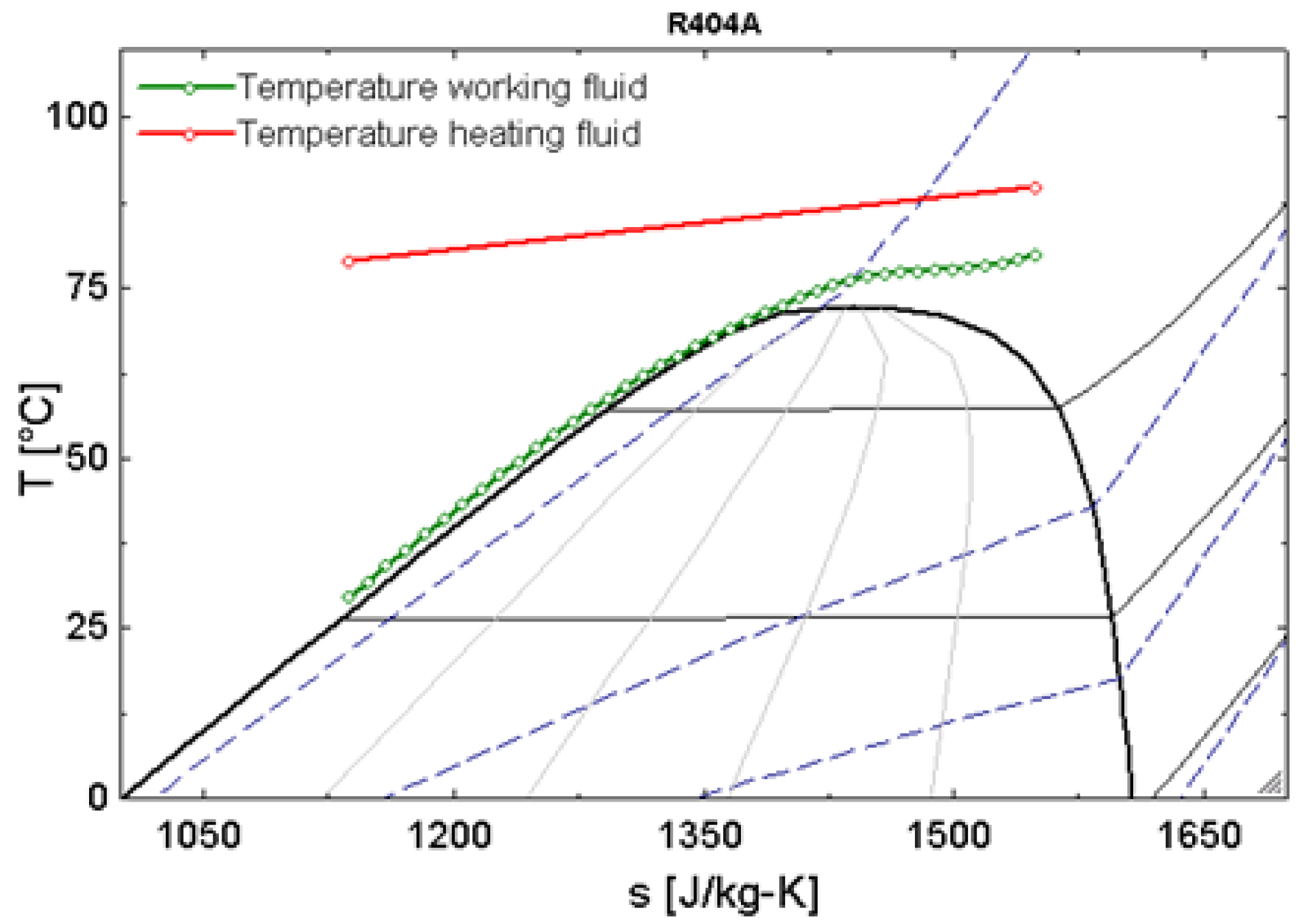
2.1. Transcritical Organic Rankine Cycle and Supercritical Heat Transfer in the Heat Exchanger

In transcritical ORCs, the heat addition to the organic fluid in the heat exchanger occurs at supercritical state. Organic fluids have relatively low critical temperature and pressure, compared to water/steam that is used as working medium in classical Rankine cycles. Hence, organic fluids can be pressurized directly to their supercritical pressure and heated in supercritical state while omitting the two-phase region. By bypassing the isothermal boiling process, a better thermal match is found between the temperature curve of the heating fluid and the working fluid, reducing entropy generation and thus raising the Second Law cycle efficiency.
A representative supercritical heating process is depicted in Figure 1, showing the temperatures of the heat transfer fluid and an organic fluid R-404A, with a pinch point temperature difference of 10 K, which exists at the exit of the heat exchanger (the organic fluid’s outlet).
As a part of this study, a helical coil heat exchanger suitable for operating at supercritical conditions in an ORC system was designed and constructed. For simulation of the heat exchanger the engineering equation solver (EES) [22] was selected. The modeling of the heat transfer process is performed with the logarithmic mean temperature difference (∆Tlog) (LMTD)-method [23]. Heat transfer correlations available from the literature (Petukhov et al. [6], Garimella [14], Mokry et al. [15]) were used for determining the heat transfer coefficients under supercritical conditions at the coil side of the helical coil heat exchanger. The estimated accuracy of these heat transfer correlations is ~20% [14,15].
In order to account for the correlation uncertainty, the helical coil heat exchanger was oversized by 20%. The heat exchanger is considered to have a counter-current flow. The maximum required heat capacity is 41 kWth. This component is the first of this kind specially designed and built for an ORC installation suitable for operating at relatively high pressure and temperature (supercritical conditions). The heat exchanger was designed to operate at a pressure of 42 bar and temperature of 100 °C, while the critical pressure and temperature of the working fluid R-404A is 37.2 bar and 72 °C respectively. An intensive simulation study for selecting an organic fluid suitable for this application was also presented [24]. The decision to work with R-404A was due to the relatively low critical pressure and temperature, the fact it is commercially available (and widely used in HVAC & R systems) and of relatively low cost, which is of high importance in order to keep the total expense of the complete engine low. However, while the ozone depletion potential (ODP) is zero its global warming potential (GWP) has a relatively high value of 3922, which provides room for the use of other fluids (and R-404A replacements), once this organic fluid is removed from use.

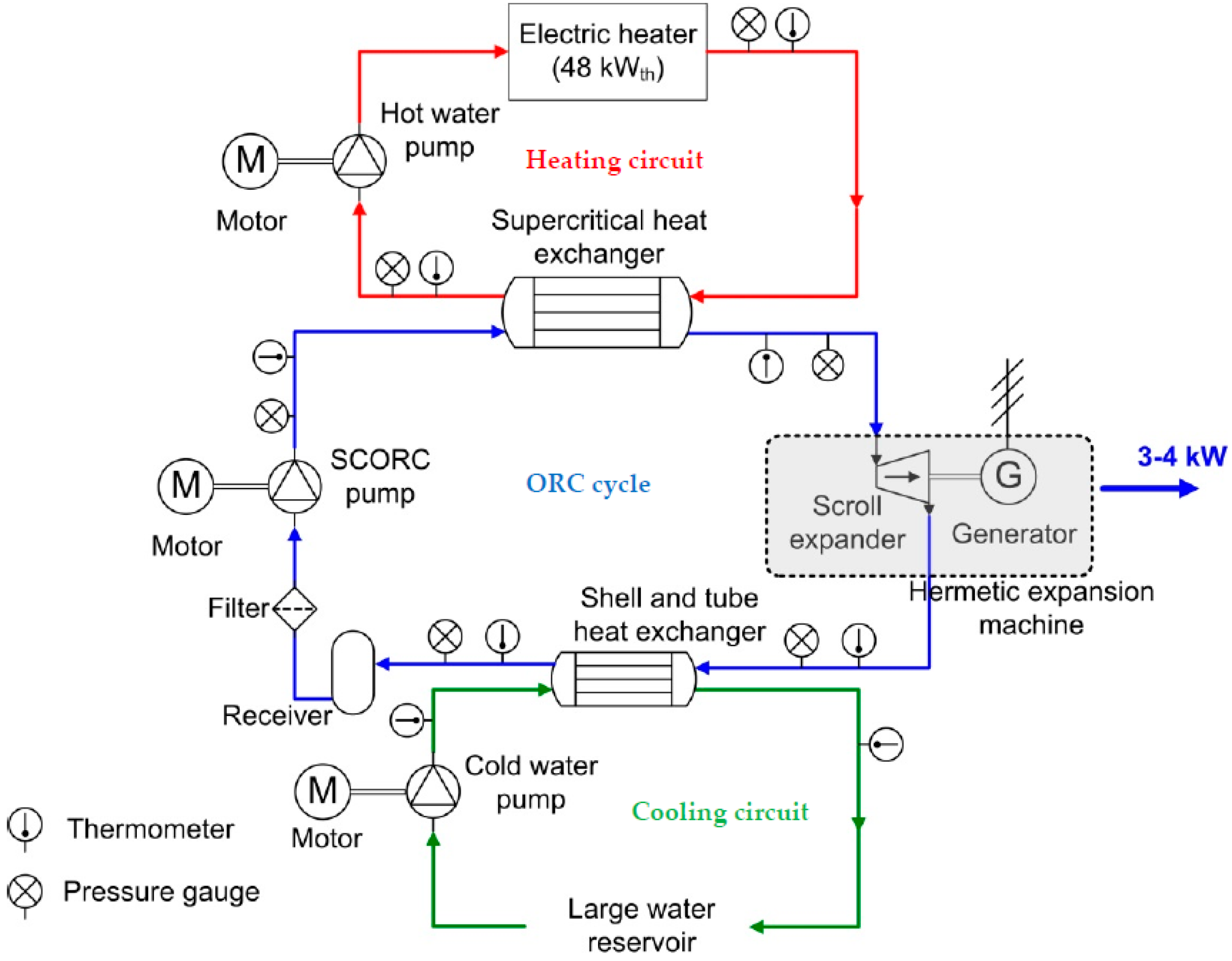
2.2. Description of the Concentrated Photovoltaic/Thermal-Rankine Set-up

A small-scale solar ORC installation with a net capacity of 3 kW was designed and built in Athens (Greece) [25,26]. The new test set-up integrates two technologies in one system: the concentrated photovoltaics/thermal (CPV/T) collector and the transcritical ORC. This system comprises three circuits: the heating circuit denoted with the red line and consisting of solar PV collectors (Figure 2); the cooling circuit which is where the condenser is located and is marked with the green line, and the ORC engine which is represented with the blue line.
A solar PV collector is a combination of a photovoltaic panel and a solar thermal collector that simultaneously generates heat and electricity. The low grade excess heat from the CPV/T circuit is utilized in the supercritical heat exchanger located in the ORC engine. However, it should be emphasized that the first tests were done in the laboratory where instead of a solar collector an electrical heater with a capacity of 48 kWth was used. Each component was tested in this installation under controlled conditions. However, the main focus in the project was on evaluating the performance of the heat exchanger and the expander (inverted scroll compressor). On the component level the ORC (blue line) consists of a pump, a heat exchanger (evaporator, vapour generator), an expander/turbine (inverted compressor) and a condenser. There is no big variation of the components of the ORC engine installed in the laboratory and the field installation. Concerning the cooling (green line), in the laboratory conditions a cooling water circuit represented by a large reservoir with a conventional shell-and-tube heat exchanger was used, while in the field installation an evaporative condenser was utilized in order to maintain the condensing pressure of the organic fluid as low as possible, due to the pump’s inlet limitation of 17 bar. Figure 2 illustrates the layout of the experimental test set-up installed in the laboratory.
In order to improve the overall cycle efficiency of ORCs, a proper selection and design of all the components is essential. The aim of this work is to present the performance evaluation of the supercritical heat exchanger, particularly designed for this ORC installation.

Uncertainty Analysis

For the first measurements, the supercritical heat exchanger was tested in the laboratory where an electrical heater with a capacity of 48 kWth was used instead of solar collectors (Figure 2). The temperature range of the heat source that can be tested is between 65 °C and up to 100 °C. This counts for both technologies, the electrical heater and the solar collectors.
During the measurements, the pressure of the heat source (water) is kept stable at 3 bar while the pressure of the organic fluid (R-404A) was varied between 14 bar and 42 bar. Furthermore, in this work the results of the temperature and pressure measurements conducted at supercritical state in the heat exchanger are reported. In order to evaluate the performance, a Pt100 temperature sensor and a type 21Y differential pressure transducer (manufactured by Keller, Winterthur, Switzerland) are placed at the inlet and at the outlet of the heat exchanger and the heat source (electric heater), respectively. All sensors (eight temperature sensors and six pressure transducers) have high accuracy of ±0.2 °C temperature error and 1% full scale pressure error. The positioning of the pressure and temperature sensors is indicated in Figure 2. Estimated uncertainties between the calculations from the pseudo-pure fluid equations and the full mixture model such in the case of R-404A are on average 0.01%. These equations are valid for the temperature range between 200 K and 450 K and can be extrapolated to higher temperatures. The accuracy of the density is 0.1%, but the critical region is excluded. There are differences of 0.1% up to 0.5% when taking the speed of sound and the heat capacity into consideration [27].
While running the measurements the temperature and pressure values at the inlet of the heat exchanger were kept stable. It is important to mention that the heat exchanger is well insulated, which means that the heat loss to the environment is reduced.
Mass flow meters were not included in the installation since all the measurements were done at steady-state conditions. A diaphragm type positive displacement (SCORE) pump, Hydra Cell model G10 (G10XKBTHFECA, (Figure 2), Wanner International Ltd., Hampshire, UK) is used for the circulation of the organic fluid R-404A. The characteristic curve of the pump has a linear function of the flow rate with the speed and the 0.0205 (L/min)/rpm parameter provides a very reliable calculation of the volumetric flow rate. The estimated accuracy of this method is 2% [26]. From the measured temperature and pressure of the organic fluid at the pump’s outlet and by using EES [22]/REFPROP [28] database for R-404A the mass flow rate is then calculated [29]. The relative measurement error for each parameter (mean value) is listed in Table 1.

3. Design Procedure of the Supercritical Heat Exchanger

In this project a small-medium enterprise (SME) company specialized in constructing tubular heat exchangers was involved [30]. Two types, helical coil and shell-and-tube heat exchangers were evaluated. However, due to several advantages a helical coil heat exchanger was selected at the end. Helical coil heat exchangers are widely used in various processes due to the advantages compared to other (tubular) types of heat exchanger, such as easy integration to the system, relatively simple design and manufacturing, operation at high pressure, suitable under conditions of laminar flow or low flow rates at shell (annular) side, cost-effectiveness.

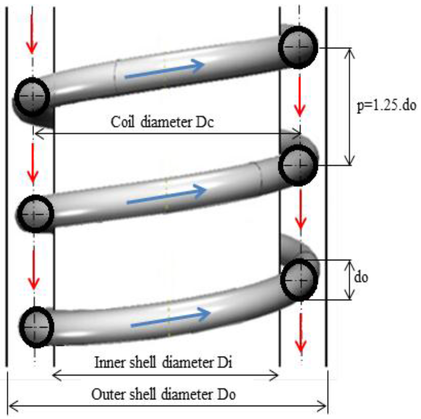
3.1. Design Characteristics of the Helical Coil Heat Exchanger

The heat exchanger is designed for maximum values of the flow rates at the tube and shell side respectively and a maximum heat transfer of 41 kWth. During the design procedure the pinch point temperature difference was fixed at 10 K. In accordance with the required heat transfer capacity (41 kWth) the heat exchanger surface was calculated in EES. Moreover, the design and construction of the supercritical heat exchanger depends on the hot/cold side fluid characteristics, such as the mass flow rates, inlet/outlet temperature and fluid properties (density, heat capacity, dimensionless numbers, etc.). At the hot side of the heat exchanger the inlet temperature of the water is 95 °C, while on the cold side an organic fluid (R-404A) circulates with an inlet temperature of 27 °C, resulting in a pinch point temperature difference at the outlet of the heat exchanger of 10 °C. The mass flow rate of both fluids was fixed at 2.5 kg/s and 0.25 kg/s at the hot and cold side respectively. At the low pressure side the maximum operating pressure is fixed and was kept stable at 3 bar while at the high pressure side the pressure is 38.5 bar or ~5% higher than the critical pressure of the organic fluid (37.2 bar). These pre-determined nominal input parameters are summarized in Table 2.

Design Parameters of the Helical Coil Heat Exchanger

The helical coil heat exchanger consists of an annular portion of two concentric cylinders in which a metal coil tube is fitted. For designing this kind of heat exchanger and for determining the heat transfer coefficients a simplified procedure described by Patil et al. [31] was followed. In order to meet the heat transfer requirements the dimensions of both cylinders are determined by the velocity limitations. The heat source (water) flows in the downward direction on the annulus side while the R-404A working fluid circulates in the upward direction in the helical coil. The heat transfer takes place across the coil wall.
The minimum clearances between the shell walls (annulus) and the coil and between two consecutive turns of the coil can be varied. The pitch, which is the spacing between consecutive coil turns (measured from the center to center) is set here at p = 1.25 × d0, which is a common design value in such heat exchangers. Figure 3 presents the configuration of the helical coil heat exchanger.
The input parameters, which are also used during the design of the helical coil heat exchanger, are [31]:
-
The coil length Lcoil, needed to make Ncoil turns: L coil = N coil ( π d o ) 2 + p itch 2
-
The volume occupied by the coil: V c = π 4 d o 2 L coil
-
The volume of the shell-side (annulus): V a = π 4 ( D o _ in 2 D i _ out 2 ) p itch N coil
-
The volume available for the flow of fluid in the annulus: V f = V a V c
-
The shell-side equivalent diameter of the coiled tube: D e = 4 V f / π d o L coil

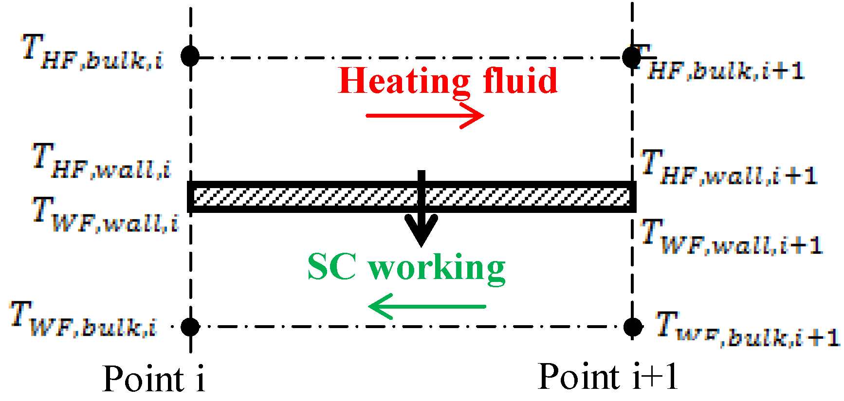
3.2. Methodology for Designing the Heat Exchanger

A widely used method of calculating the heat transfer capacity UA and eventually sizing the heat exchanger is the logarithmic mean temperature difference LMTD method, applied between the inlet and outlet of the heat exchanger by Cayer et al. [32], Roy et al. [33], and Claesson [34] and given by Equation (1):
Q = U × A × Δ T log = U × A × Δ T 1 Δ T 2 ln ( Δ T 1 Δ T 2 )
where Q is the heat transferred, U is the overall heat transfer coefficient, A is the total heat transfer area, and Δ T log is the logarithmic temperature difference or LMTD.
However, the LMTD-method is based on constant fluid properties. When working with fluids in the supercritical state this assumption leads to incorrect results. A possible solution is to discretise the heat exchangers into a large number of control volumes so that the property variation in each step is small and an average constant value, different for each step, can be assigned within each volume.
A single control volume with the main variables and parameters is presented in Figure 4. The discretization is performed in EES where the overall enthalpy change is divided in equal differences ∆h for one of the streams in N control volumes (here N = 20). In each control volume the heat transferred is equal because ∆h and the mass flow rate of the working fluid m ˙ WF are considered as constants (for a particular volume) and can be described by the calculation method below:
Q ˙ i = m ˙ HF C p HF ( T HF , bulk , i T HF , bulk , i + 1 )
Q ˙ i = m ˙ HF ( h HF , bulk , i h HF , bulk , i + 1 )
Q ˙ i = h ¯ HF A out , i ( T ¯ HF , bulk , i T ¯ HF , wall )
Q ˙ i = h ¯ HF A in , i ( T ¯ WF , wall , i T ¯ WF , bulk , i )
Q ˙ i = U ¯ out , i A out , i L M T D i
T ¯ HF , bulk , i = T HF , bulk , i + T HF , bulk , i + 1 2
T ¯ HF , wall , i = T HF , wall , i + T HF , wall , i + 1 2
T ¯ WF , bulk , i = T WF , bulk , i + T WF , bulk , i + 1 2
T ¯ WF , wall , i = T WF , wall , i + T WF , wall , i + 1 2
L M T D i = ( T HF , bulk , i + 1 T WF , bulk , i + 1 ) ( T HF , bulk , i T WF , bulk , i ) ln ( T HF , bulk , i + 1 T WF , bulk , i + 1 T HF , bulk , i T WF , bulk , i )
U ¯ out , i = 1 h ¯ HF , i + 1 h ¯ WF , i ( d o d i ) + ( d o 2 ) ln ( d o d i ) λ tube
where Qi is the heat transferred in one control volume, m is the mass flow rate, T is the temperature of the fluid, U is the overall heat transfer coefficient, Cp is the specific heat capacity, A is a surface area, d is a tube diameter, λ is a thermal conductivity of the tube and h is the enthalpy. Among the subscripts WF is working fluid, HF is heating fluid, out is outer conditions/area, in is inner conditions/area, bulk is at bulk conditions, wall is at wall conditions and i is the iteration step.
Discretization of the fluid volumes and the wall in between is advisable to be in the range between 20 and 40 equal distances. Considering fewer discretization steps, for instance 10, leads to less accurate results. The deviation in accuracy when comparing 20 and 10 steps is 0.6% in enthalpy changes and is calculated from the model developed in EES, while above 40 steps the required computational time will increase too much.

3.2.1. Determining the Heat Transfer Coefficient at the Outside of the Helical Coil

In a helical coil heat exchanger, the heating fluid is circulated over the wall of the helically coiled tube that is fitted in the annulus and is made of two concentric cylinders. As the flow rate of the heating fluid is rather low, the following Nusselt-correlation, valid for Reynolds number Re between 50 and 10,000 can be used Equation (13), Coates [35]):
N u = 0.6 R e 0.5 P r 0.31
For higher Reynolds number (Re > 10,000), the correlation derived by Kern [36] (Equation (14)) is used:
N u = 0.36 R e 0.55 P r 1 3 ( μ / μ w ) 0.14
where µ is the fluid’s bulk viscosity, μw is the fluid’s viscosity at the wall temperature, the Prandtl number: P r =   C p μ k , and the Reynolds number: R e = 4   m ˙ HF π D e μ .
The thermodynamic fluid properties and Pr number are calculated at the average values of the inlet and outlet temperatures of each control volume, while the Re number is calculated from the equation presented in the text by taking into consideration the shell-side equivalent diameter of the coiled tube De as a characteristic length.

3.2.2. Determining the Heat Transfer Coefficient Inside the Coiled Tube

At the helical coil side the supercritical fluid is circulated in upward flow. Several correlations can be found in the literature for the calculation of the heat transfer coefficient under supercritical conditions. The conventional heat transfer correlations for single phase flow (calculation of the Nusselt number) cannot be used in the current case, due to the variations of the fluid properties around the critical point. For the calculations of the helical coil heat exchanger three correlations: Petukhov et al. [6], Garimella [14] and Mokry et al. [15] are identified and calculated independently. The results obtained from the computation process are then compared.
Petukhov et al. [6] developed correlations for supercritical fluid parameters. The correlations have a correction factor, which neutralizes the effect of the variations of the thermophysical properties around the pseudo-critical point and provides more stable and accurate results. The Nusselt-correlation proposed by Petukhov et al. [6] for carbon dioxide in the supercritical range at high temperature drops takes into account the difference in properties between the wall and the bulk temperature.
Garimella [14] developed heat transfer correlations for supercritical heat transfer based on measurement data from R-404A and R-410A. Three heat transfer regions have been identified based on the state of the heat transfer fluid: liquid-like region, pseudo-critical transition and gas-like region. For each region separate correlations for Nusselt number and friction factor have been identified. The flow regime boundaries are listed in Table 3. These correlations are valid for the following working range of the mass flux and critical pressure: 200 kg/m2s < G < 800 kg/m2s and 1.0 < p/pcr < 1.2.
In the literature the majority of empirical heat transfer correlations were published in the period of 1960s–1970s. Back at that time the experimental techniques were not at the same advanced level as they are today. For instance, new thermophysical properties of water have been recognized in 1990s, by considering the peak in thermal conductivity in the pseudo-critical and critical region within the pressure range between 22.1 MPa to 25 MPa. Based on the updated data for thermophysical properties of water a new or modified heat transfer correlation was developed and evaluated by Mokry et al. [15]. This correlation is valid for the following working range of the mass flux: 200 kg/m2s < G < 1500 kg/m2s.
The heat transfer coefficient of the organic fluid is calculated by employing the modified correlations for turbulent flow for supercritical heat transfer in straight tubes of Petukhov, Garimella, Mokry (Table 4 and Equations (16)–(22)). However, the effect of the secondary flow that appears in the helical coil tube due to the coil curvature and the centrifugal forces has to be taken into consideration. This effect was first analytically studied by Dean [37,38] where the coil geometries are taken into account and was characterized by a single non-dimensional parameter the Dean number D e = R e r i R c , for very small Reynold numbers [39]. In the particular case, the Reynolds numberof the organic (working) fluid is relatively high and is in the range of 105,000–150,000. Also, the Dean number has high values and is in the range of 24,000–35,500. Therefore, an alternative solution was considered. In the literature there is a limited data on the investigations performed in a turbulent developing flow in coiled tubes. Schmidt [39] derived a coefficient F helical = F helical [ R e , r i / R c ] for a wide application range taking into account the geometry of the coiled tube. This safety coefficient was used in order to describe the effect of the tube’s curvature and the secondary flow that have influences on the heat transfer in the helical coiled tube. Therefore, the heat transfer correlation(s) for a straight tube is then corrected by multiplying it with the safety coefficient: F helical , which has a large application range:
F helical = 1 + 3.6 [ 1 r i R c ] ( r i R c ) 0.8
where Rc is the heat exchanger coil mean radius (m), ri is the coil tube inner radius with circular cross section (m), and the Reynolds number: R e = 4   m ˙ WF π d i μ .
This safety coefficient is applicable for Reynolds numbers 2 × 10⁴ < Re < 1.5 × 10⁵ and for 5 < Rc/ri < 84. There is confidence in implementing this safety coefficient in the present work because the Reynolds number and the ratio Rc/ri = 18 are in the recommended range.

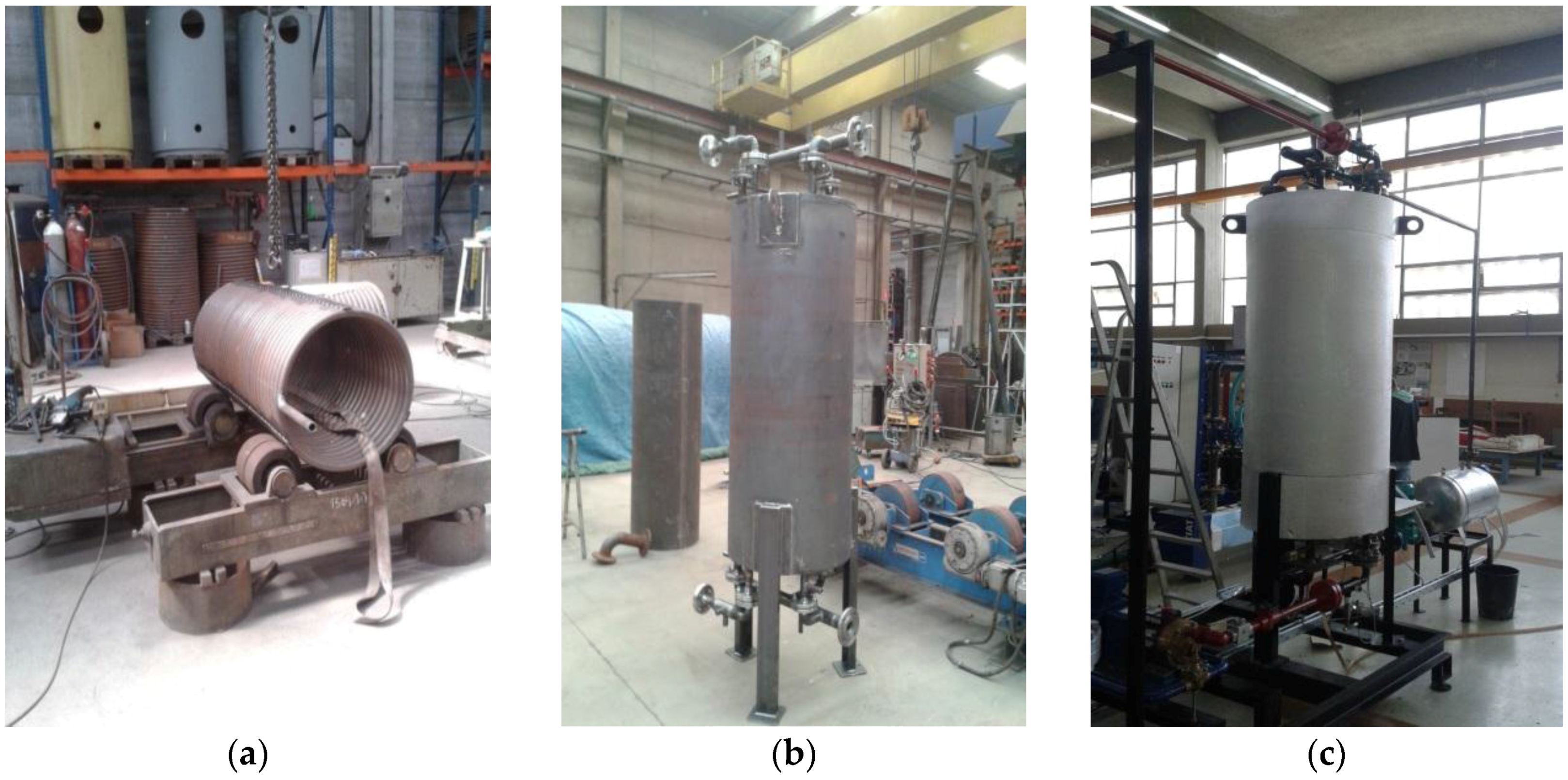
3.3. Computational Results and Final Dimensions of the Heat Exchanger

All three heat transfer correlations were developed independently, but give similar results. The most suitable configurations are considered the one with the outer tube diameter of d o = 0.028   m and are highlighted in bold in the Table 5. The tube thickness is t   = 1.5  mm , while the total tube length is ~60 m. For constructional reasons the coil radius is fixed to 0.3 m. A smaller radius would be more difficult to construct, while a larger radius would decrease the fluid velocity at the annulus side and reduce the heat transfer. The spacing between the coil and the annulus wall is limited to 20 mm. This is the smallest gap allowed for construction and is determined by the velocity of the heating fluid—water in the annulus needed to meet the heat transfer requirements and the tube pitch is set here at p itch = 1.25 d o . The optimal selection of the heat exchanger is accomplished taking into account that the velocity and pressure drop in the tube and annulus are within the allowable ranges. The velocity ranges of the working fluid were fixed at minimum 0.5 m/s and maximum 2.17 m/s, while the overall pressure drop was neglected in the calculation and was afterwards calculated and should be lower than 40 kPa. The heating fluid flows at relatively low flow rates (Re = 4200–5900, R e =   4   m ˙ HF π D e μ ).
The selected heat transfer correlations for this project were developed for the working fluids CO2, R-404A, R-410A and water for different conditions than for the ORCs more than 10 years ago. Moreover, the uncertainty of these correlations is ~20%. By using these computational results for designing the heat exchanger, there is a risk that this component will not be suitable to cope and fulfil the duty of the required heat capacity of 41 kWth. Therefore, in order to account for the heat transfer correlation’s uncertainty the heat exchanger is oversized by about 20%.
In summary, the final geometrical values of the heat exchanger lead to a coil length of 66 m and inner coil diameter of 26 mm. For construction reasons however, the tube thickness was increased from 1.5 mm to 4 mm to allow curving the welded tubes (to a length of 66 m) without buckling them. The closest commercial available steel tube with a thickness of 4 mm has an outside diameter of 33.7 mm. Table 6 presents summary of the final geometrical values of the heat exchanger.
The supercritical heat exchanger after the design procedure was finally constructed by the company Deconinck-Wanson [30] from Belgium. Further, it was mounted in the ORC installation in the laboratory for testing under controlled environment. Figure 5 presents the fabricated components: Figure 5a shows the metal helical coil, Figure 5b is a final look of the constructed heat exchanger and Figure 5c the heat exchanger installed in the ORC installation.
The results from the measurements that are obtained with an electrical heater at supercritical state are reported next in this study.

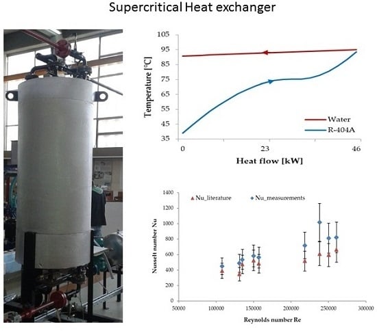
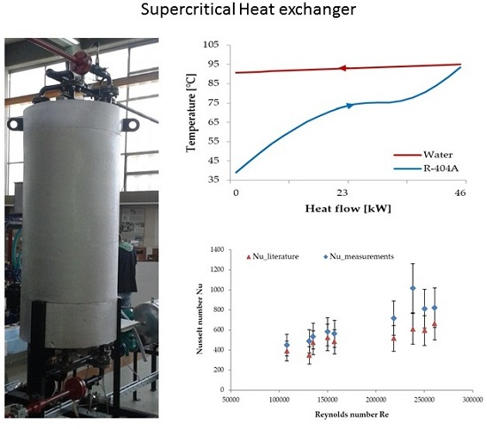
4. Testing of the Heat Exchanger

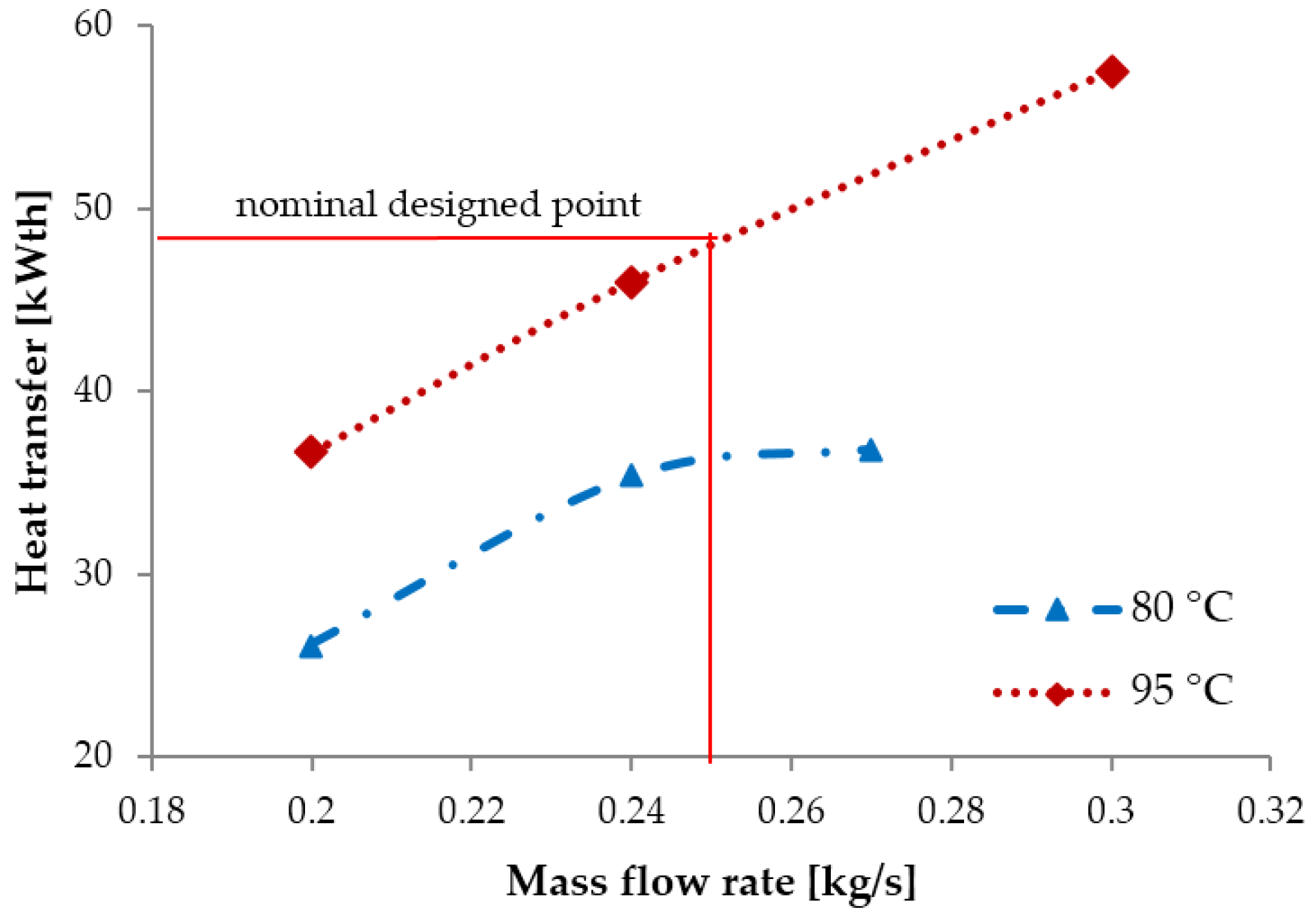
4.1. Performance Evaluation of the Heat Exchanger at Variable Mass Flow Rate of the Organic Fluid and at Heat Source Inlet Temperatures of 80 °C and 95 °C

Several measurement campaigns were performed in order to check the influence of the mass flow rate variation of the organic fluid R-404A to the heat transfer. The experiments were conducted at heating fluid (source) inlet temperatures of 80 °C and 95 °C. At these inlet temperatures the pressure and the mass flow rate remained stable at 3 bar and 2.7 kg/s, respectively. However, the inlet temperature of the organic fluid R-404A on the cold side is dependent on the mass flow rate of the fluid and the inlet temperature of the heating fluid. Hence, the performance evaluation was conducted at different mass flow rates in the range of 0.20 kg/s and 0.30 kg/s while ensuring a turbulent flow during the measurements. Once a steady state was reached all the values such as temperature, pressure and mass flow rate were recorded.
At a mass flow rate of 0.20 kg/s and heating fluid inlet temperatures of 80 °C and 95 °C the corresponding inlet temperature of the R-404A on the cold side to 26 °C and 28 °C, respectively. The operational pressure when operating at 80 °C is 42 bar, which corresponds to a pressure ~15% above the critical pressure. This results in a heat transfer in the heat exchanger of 26 kWth. At the same mass flow rate but a heating fluid temperature of 95 °C the operational pressure is 40 bar or ~10% above the critical pressure of R-404A and that yields to a heat transfer of 37 kWth.
By altering the mass flow rate to 0.24 kg/s, the inlet temperature of the organic fluid results in 28 °C and 29 °C when the inlet temperature of the heating source is at 80 °C and 95 °C, respectively. When operating near the critical pressure of the organic fluid R-404A (37.29 bar) as in the case of 38 bar pressure and a heating fluid temperature of 80 °C, a heat transfer of 35 kWth is achieved. At a heating fluid temperature of 95 °C and operational pressure of 41 bar, a heat transfer of 46 kWth was reached. Compared to the heat transfer at the lower mass flow rate of 0.20 kg/s an increased heat transfer in the heat exchanger was achieved under these conditions.
Maximum heat transfer in the heat exchanger is reached at a mass flow rate of 0.30 kg/s (0.27 kg/s). The operational pressure in these measurement campaigns with a heating fluid inlet temperature of 80 °C is 40 bar. This yielded an inlet temperature of 29 °C and heat transfer in the heat exchanger of 37 kWth. When operating at 95 °C the inlet temperature of the working fluid is 36 °C and the operational pressure is 38 bar. That leads to a heat transfer of 57.5 kWth in the heat exchanger.
By analysing the results from the measurements it can be noticed that there is a variation of the pressure as a function of the mass flow rate because these parameters follow the characteristic curves of the pump and the system. The system curve consists of the expander characteristic curve and the pressure losses in the components (valves, fittings, tubes). During the measurements, by increasing the speed of the volumetric expander the pressure was lowered and the mass flow rate increased.
The pressure drop over the helical coiled heat exchanger was also determined from the measurements. Increasing the mass flow rate resulted in a higher pressure drop over the helical coiled tube and it was in the range of 0.6 bar up to 1 bar.
Figure 6 presented above shows that by changing the mass flow rate of the organic fluid and constant flow rate of the heating fluid, results in an increased heat transfer. The Reynolds number is in the range of 105,000 up to 150,000 and higher Reynolds number R e = 4   m ˙ WF π d i μ yields an increased heat transfer due to the higher mass flow rate. Comparing the results from the measurements to the nominal designed values such as the heating fluid inlet temperature of 95 °C and a mass flow rate of 0.25 kg/s (Table 2) a heat transfer of 48 kWth is obtained in the heat exchanger. This yields a heat transfer enhancement of ~10% compared to the designed specification.
From this analysis it can be concluded that at lower mass flow rates the heat transfer across the coil wall of the heat exchanger decreases. For optimal operation the mass flow rate should be close to the designed specifications. Further, compared to the nominal designed values an enhanced heat transfer in the heat exchanger of ~10% was achieved.

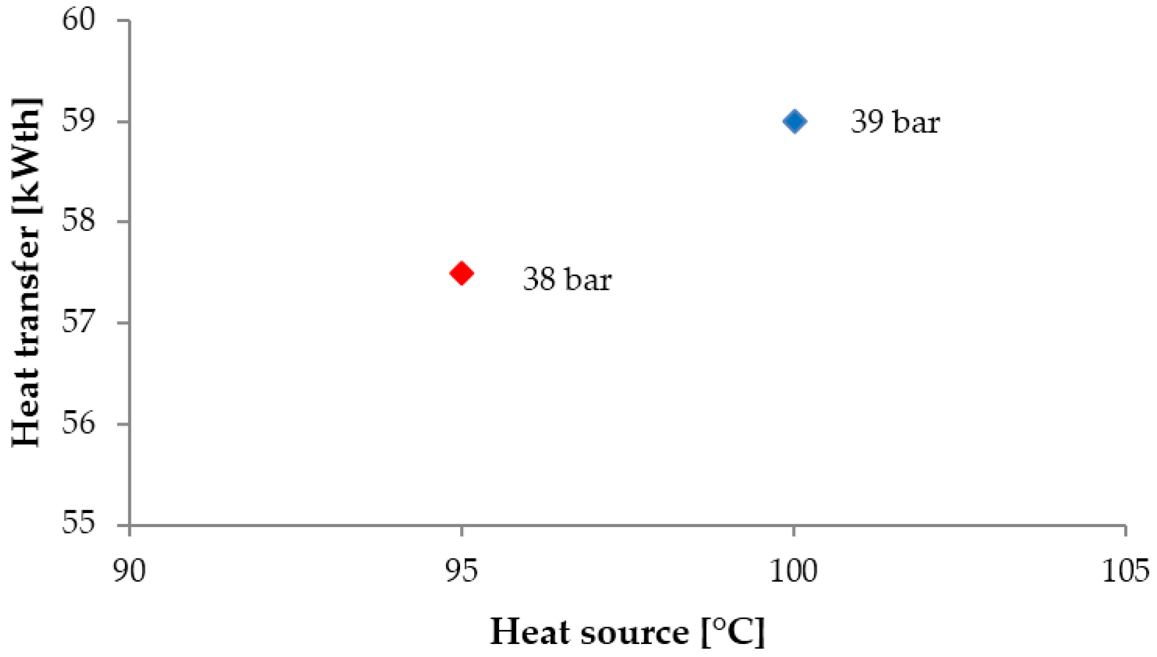
4.2. Comparison of the Performance at Constant Mass Flow Rate of 0.30 kg/s and Heat Source Inlet Temperatures of 95 °C and 100 °C

A limited number of measurements for the heating fluid inlet temperature of 100 °C could be performed. These measurements were obtained only at higher values of the organic fluid’s mass flow rate such as 0.30 kg/s. The mass flow rate is tightly related to the pump speed, the inlet pressure limitation of the pump that corresponds to 17 bar and the temperature of the cooling fluid. Furthermore, the concentrated PV/T collectors have a temperature limitation of 100 °C.
Figure 7 presents the heat transfer rate in the heat exchanger as a function of two different inlet temperatures at the hot side such as 95 °C and 100 °C. It can be noticed from this figure that at 95 °C the maximum heat transferred at the coil side is 57.5 kWth. The operating pressure under these conditions is 38 bar and is near to the critical pressure of the organic fluid. Further, at the inlet temperature of 100 °C the operational pressure is 39 bar. A maximum heat transfer of 59 kWth is achieved at the coil side of the heat exchanger at these operating conditions.
However, by comparing the results from the measurements in terms of the heat transferred at 95 °C and 100° C it can be noticed that there is a very small difference (~2 kWth). Hence, for optimum operation of the heat exchanger high temperatures, particularly higher than 95 °C, are not mandatory. This conclusion is of great importance because of the temperature limitation of the solar collectors (PVs). Once the heat exchanger is tested in the CPV/T-ORC installation, an optimum operation can be expected at 95 °C. Moreover, the mass flow rate of the organic fluid should be maintained relatively high (close to the designed specifications) and the operating pressure should be close to the critical pressure of the organic fluid. In this case this yields to a pressure ~5% higher than the critical pressure of R-404A.

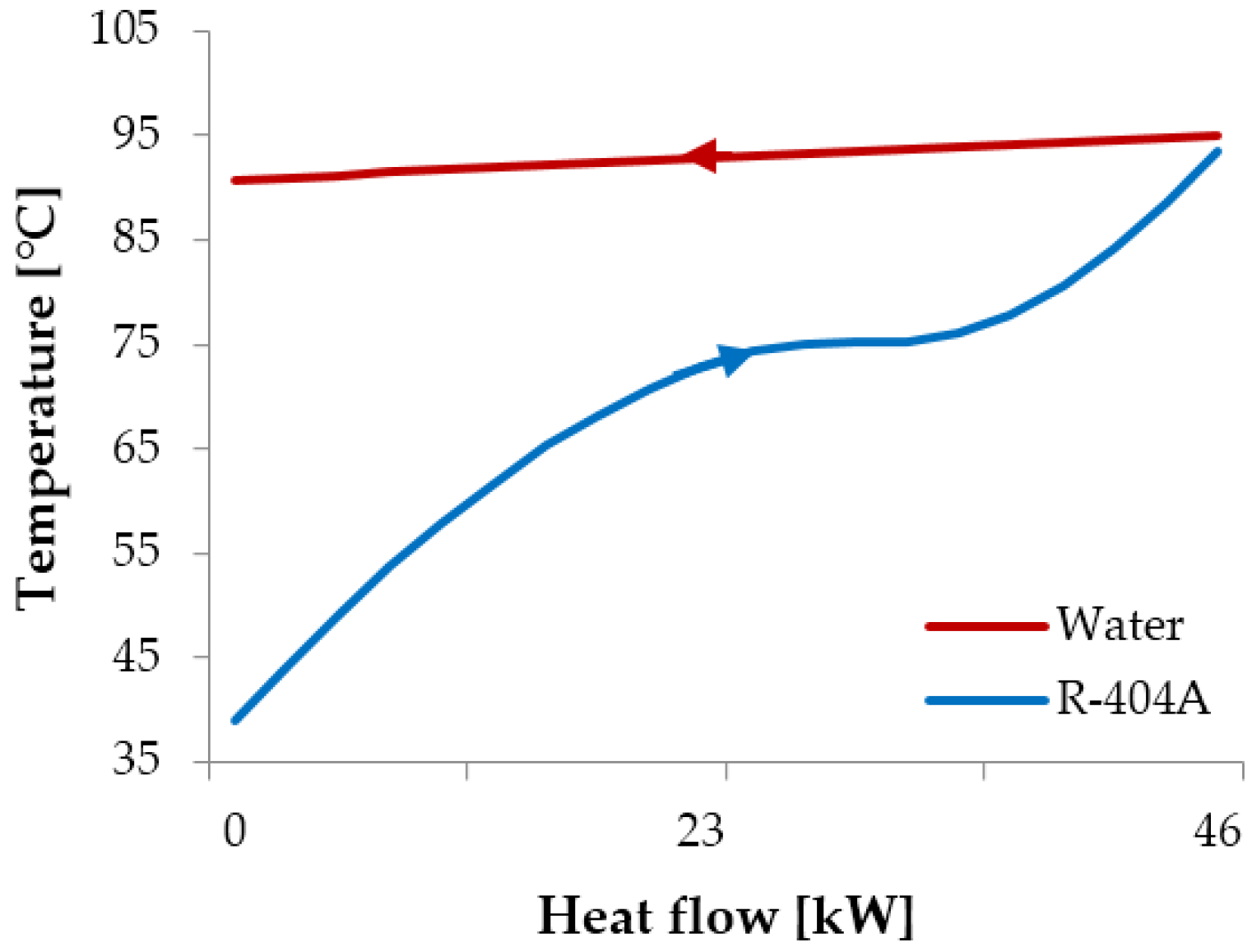
4.3. Analysis of the Thermal Match in the Helical Coil Heat Exchanger at 95 °C

A thermal match analysis at inlet temperature of the heating fluid of 95 °C is presented next. The mass flow rates of the heating and working fluid are 2.7 kg/s and 0.30 kg/s, respectively, and are close to the designed specifications. During the design, the pinch point temperature difference was fixed at 10 K. Furthermore, temperature measurements are possible only at the inlet and outlet of the cold and hot side of the heat exchanger. Therefore, the pinch point temperature difference was calculated from a model developed in the EES environment.
At the operating condition of 95 °C, the inlet temperature of the organic fluid is 36 °C. The pinch point temperature difference is determined by the flow rates and the inlet temperatures of the heating and organic fluids, which is less than 10 K. An improved thermal match between the heating fluid and the organic fluid of only 2 °C is reached at the exit of the heat exchanger. Figure 8 shows the improved thermal match between the heating and organic fluid at the exit of the helical coil heat exchanger at a heating fluid inlet temperature of 95 °C.
For inlet temperatures of 80°C and 100 °C of the heating fluid (water), the thermal match profile is similar to the 95 °C inlet temperature of the heating fluid.

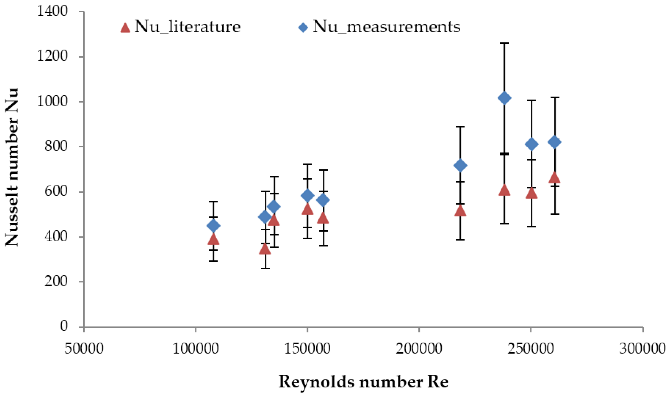
4.4. Measurement Results

In this analysis the data obtained from the measurements (temperature, pressure, mass flow rates etc.) is evaluated. However, a supercritical state in the heat exchanger was difficult to achieve. Therefore, in this article only a limited number of data points could be presented and evaluated.
For a measured end-point temperature, the flow rate in the annulus and the properties of the heating fluid remain stable. Due to the limited data points obtained from the measurements the uncertainties of the new Nusselt number is in the range between 16% up to 32%. This implies that the errors for most measurement points fall within the uncertainty range of the literature correlation which is 25%. Therefore for deriving a correlation with a better accuracy more measurements and data points need to be obtained and evaluated. Figure 9 presents a comparison of the Nusselt number determined from the literature correlation [15] and the Nusselt number from the measurements.
In the design process of the supercritical heat exchanger a safety factor of 20% was implemented in order to account for the heat transfer correlation uncertainty. Due to the limited number of measurements at supercritical state and the relatively high uncertainty (higher than the literature correlation), can be concluded that deriving a correlation that has a higher accuracy than the literature correlation is essential.
On the other hand, by reducing the size of this component, the cost will be decreased and an economic benefit on the complete installation will be achieved. The benefit would be more accurate design and use of less material, which leads to lower costs.

5. Conclusions

In recent years a lot of attention has been paid to improving the overall efficiency of ORC technologies. One way to improve the cycle efficiency is by ensuring supercritical heat transfer in the heat exchanger.
In this work a supercritical heat exchanger of helical coil type was first designed and then evaluated under real operational conditions. Three heat transfer correlations available from the literature were employed for the design of the heat exchanger. These heat transfer correlations were derived for different working fluids and conditions than the tested ORCs. Therefore, to account for the uncertainties of the heat transfer correlations the heat exchanger was oversized by 20%.
Performance evaluation of the constructed heat exchanger was performed at supercritical working conditions (laboratory conditions) by examining the influence of several different parameters. The tests were performed at three different inlet temperatures of the heating fluid such as 80 °C, 95 °C and 100 °C. The mass flow rate of the heating fluid was kept stable at 2.7 kg/s and the values of the organic fluid were altered between 0.20 kg/s up to 0.33 kg/s. At higher mass flow rate of the organic fluid an increased heat transfer in the heat exchanger was achieved. Further, by comparing the results from the measurements with the designed specifications an enhanced heat transfer of ~10% was performed. Moreover, from the thermal match analysis a pinch point temperature difference of only 2 °C was reached at the exit of the heat exchanger, which is lower than the designed value of 10 K.
From the arguments mentioned in this work, it can be concluded that more accurate design of the heat exchanger with appropriate correlations leads to increased heat transfer in the heat exchanger and the cycle efficiency. Therefore, a new more accurate correlation for an optimal design of a heat exchanger needs to be derived.

Acknowledgments

The research leading to these results has received funding from the European Union’s Seventh Framework Programme managed by REA-Research Executive Agency, http:ec.europa.eu/research/rea ([FP7/2007-2013] [FP7/2007-2011]) under grant agreement No. 315049 [CPV/RANKINE], FP7-SME-2012. Ghent University acknowledges all the project partners for the fruitful cooperation. The results presented in this paper have been obtained within the frame of the IWT SBO-110006 project The Next Generation Organic Rankine Cycles, funded by the Institute for the Promotion and Innovation by Science and Technology in Flanders. This financial support is gratefully acknowledged. A grateful acknowledgment to Marnix Van Belleghem and the company Deconinck-Wanson for the valuable remarks concerning the design and the applied professionalism for constructing of the helical coil heat exchanger.

Author Contributions

Marija Lazova is the leading researcher of this work. The experiments were conceived and designed by Marija Lazova and Henk Huisseune. George Kosmadakis was responsible for performing the experiments in the laboratory. Marija Lazova, Henk Huisseune and Alihan Kaya analyzed the data from the measurements. Steven Lecompte contributed with analysis tools. Michel De Paepe reviewed the final work.

Conflicts of Interest

The authors declare no conflict of interest.

Abbreviations

ATotal heat transfer area (m2)
CO2Carbon dioxide
CPV/TConcentrated Photovoltaic/Thermal
CpSpecific heat capacity (J/kg·K)
diTube inner diameter (mm)
doTube outer diameter (mm)
DcCoil diameter (m)
DeShell-side equivalent diameter of the coiled tube (m)
DiInner shell diameter (m)
Di_outOuter side of the inner shell diameter (m)
DoOuter shell diameter (m)
Do_inInner side of the outer shell diameter (m)
dbaselineBaseline diameter (mm)
dactualActual diameter of the tube (mm)
EESEngineering equation solver
fFriction factor (-)
GMass flux (kg/m2s)
HTCHeat transfer coefficient (W/m2k)
HcoilHeight of the HX (m)
hAverage enthalpy
LMTDLogarithmic mean temperature difference (∆Tlog)
LCoil length (m)
mMass flow rate (kg/s)
NcoilNumber of coil turns
ORCOrganic Rankine Cycle
pPressure (bar)
pPressure drop (bar)
pitchSpacing between consecutive coil turns
Rc:Coil radius (m)
riTube radius (m)
QHeat transfer (kw)
QiHeat transferred in one control volume (kw)
TTemperature (°C)
TTemperature difference (°C)
tTube thickness (mm)
UOverall heat transfer coefficient (W/m2k)
VaVolume of the shell-side (annulus) (m3)
VcVolume occupied by the coil (m3)
VfVolume available for the flow of fluid in the annulus (m3)
DeDean number
PrPrandtl number
ReReynolds number
NuNusselt number
µFluid’s bulk viscosity (kg/ms)
μwFluid’s viscosity at the wall temperature (kg/ms)
λThermal conductivity of the tube (W/mk)
δCurvature ratio (-)

References

  1. Lecompte, S.; Huisseune, H.; van den Broek, M.; Vanslambrouckb, B.; de Paepea, M. Review of organic Rankine cycle (ORC) architectures for waste heat recovery. Renew. Sustain. Energy Rev. 2015, 47, 448–461. [Google Scholar] [CrossRef]
  2. Bringer, R.P.; Smith, J.M. Heat transfer in the critical region. AIChE J. 1957, 3, 49–55. [Google Scholar] [CrossRef]
  3. Dickinson, N.L.; Weich, C.P. Heat Transfer to Supercritical Water; The American Society of Mechanical Engineers: New York, NY, USA, 1958; pp. 745–751. [Google Scholar]
  4. Shitsman, M.E. Heat transfer to water, oxygen and carbon dioxide in the approximately critical range. Teploenergetiky 1959, 1, 68–72. [Google Scholar]
  5. Krasnoshchekov, E.A.; Protopopov, V.S. Heat transfer at supercritical region in flow of carbon dioxide and water in tubes. Therm. Eng. 1959, 12, 26–30. (In Russian) [Google Scholar]
  6. Petukhov, B.S.; Krasnoshchekov, E.A.; Protopopov, V.S. An Investigation of Heat Transfer to Fluids Flowing in Pipes under Supercritical Conditions; ASME University of Colorado: Boulder, CO, USA, 1961; pp. 569–578. [Google Scholar]
  7. Shitsman, M.E. Impairment of the heat transmission at super-critical pressures. Teplofiz. Vysok. Temp. 1963, 1, 267–275. (In Russian) [Google Scholar]
  8. Bishop, A.A.; Sandberg, R.O.; Tong, L.S. Forced Convection Heat Transfer to Water at Near Critical Temperatures and Supercritical Pressures; WCAP-5449; CONF-650603-1; Westinghouse Electric Corp.: Pittsburgh, PA, USA, February 1964. [Google Scholar]
  9. Ackermann, J.W. Pseudo-boiling heat transfer to supercritical pressure water in smooth and ribbed tubes. J. Heat Transf. 1970, 92, 490–498. [Google Scholar] [CrossRef]
  10. Yamagata, K.; Nishikawa, K.; Hasegawa, S.; Fujii, T.; Yoshida, S. Forced convection heat transfer to supercritical water flowing in tubes. Int. J. Heat Mass Transf. 1972, 15, 2575–2593. [Google Scholar] [CrossRef]
  11. Jackson, J.D.; Fewster, J. Forced Convection Data for Supercritical Pressure Fluids. Heat Transf. Fluid Flow Serv. 1975, 21540. [Google Scholar]
  12. Vikrev, Y.V.; Lokshin, V. An experimental study of temperature conditions in horizontal steam generating tubes at supercritical pressures. Teploenergetika 1 1964, 11, 12–16. [Google Scholar]
  13. Jackson, J.D.; Hall, W.B. Influences of buoyancy on heat transfer to fluids flowing in vertical tubes under turbulent conditions. In Turbulent Forced Convection in Channels and Rod Bundles; Hemisphere Publishing Corporation: Washington, DC, USA, 1979; Volume 2, pp. 613–640. [Google Scholar]
  14. Garimella, S. High Condensing Temperature Heat Transfer Performance of Low Critical Temperature Refrigerants; ARTI 21CR Program Contract number 610-20060; Air-Conditioning and Refrigeration Technology Institute: Arlington, VA, USA, 2006. [Google Scholar]
  15. Mokry, S.; Pioro, I.; Farah, A.; King, K.; Gupta, S.; Peiman, W.; Kirillov, P. Development of supercritical water heat-transfer correlation for vertical bare tubes. Nucl. Eng. Des. 2011, 241, 1126–1136. [Google Scholar] [CrossRef]
  16. Lazova, M.; Daelman, S.; Kaya, A.; Henk, H.; De Paepe, M. Heat transfer in horizontal tubes at supercritical pressures for ORC application. In Proceedings of the 10th International Conference on Heat Transfer, Fluid Mechanics and Thermodynamics, Orlando, FL, USA, 14–16 July 2014.
  17. Haskins, H.J.; Taylor, R.M.; Osborn, D.B. Development of solar receiver for an organic Rankine cycle engine. In Proceedings of the 16th Intersociety Energy Conversion Engineering Conference ‘Technologies for the Transition’, Atlanta, GA, USA, 9–14 August 1981; Volume 2, pp. 1764–1769.
  18. Amon, C.H.; Mikicb, B. Spectral Element Simulations of Unsteady Forced Convective Heat Transfer: Application to Compact Heat Exchanger Geometries. Numer. Heat Transf. A 1991, 19, 1–19. [Google Scholar] [CrossRef]
  19. Schuster, A.; Karellas, S.; Leontaritis, A.D. Influence of supercritical ORC parameters on plate heat exchanger design. Appl. Therm. Eng. 2012, 33–34, 70–76. [Google Scholar]
  20. Shao, Y.-L.; Yang, L.; Zhang, C.-L. Comparison of heat pump performance using fin-and-tube and microchannel heat exchangers under frost conditions. Appl. Energy 2010, 87, 1187–1197. [Google Scholar] [CrossRef]
  21. Lecompte, S.; Lemmens, S.; Huisseune, H.; van den Broek, M.; de Paepe, M. Multi-Objective Thermo-Economic Optimization Strategy for ORCs Applied to Subcritical and Transcritical Cycles for Waste Heat Recovery. Energies 2015, 8, 2714–2741. [Google Scholar] [CrossRef] [Green Version]
  22. Klein, S.A. Engineering Equation Solver (EES); F-Chart Software: Madison, WI, USA, 2013. [Google Scholar]
  23. Liu, H.; Kakaç, S.; Pramuanjaroenkij, A. Heat Exchangers, Selection, Rating, and Thermal Design; CRC Press: Boca Raton, FL, USA, 2012. [Google Scholar]
  24. Kosmadakis, G.; Manolakos, D.; Papadakis, G. Experimental investigation of a low-temperature organic Rankine cycle (ORC) engine under variable heat input operating at both subcritical and supercritical conditions. Appl. Therm. Eng. 2016, 92, 1–7. [Google Scholar] [CrossRef]
  25. Lazova, M.; Daenens, D.; Kaya, A.; van Belleghem, M.; Huisseune, H.; Kosmadakis, G.; Manolakos, D.; de Paepe, M. Design of a Supercritical Heat Exchanger for an Integrated CPV/T-RANKINE Cycle. In Proceedings of the Third International Seminar on ORC Power Systems, Brussels, Belgium, 12–14 October 2015.
  26. Kosmadakis, G.; Manolakos, D.; Papadakis, G. Experimental testing of a small-scale supercritical ORC at low-temperature and variable conditions. In Proceedings of the 3rd International Seminar on ORC Power Systems (ASME-ORC2015), Brussels, Belgium, 12–14 October 2015.
  27. Lemmon, E.W. Pseudo-Pure Fluid Equations of State for the Refrigerant Blends R-410A, R-404A, R-507A, and R-407C. Int. J. Thermophys. 2003, 24, 991–1006. [Google Scholar] [CrossRef]
  28. Lemmon, E.W.; Huber, M.L.; Mc Linden, M.O. NIST Standard Reference Database 23: Reference Fluid Thermodynamic and Transport Properties-REFPROP; National Institute of Standards and Technology: Gaithersburg, MD, USA, 2007.
  29. Engineering Equation Solver. Available online: http://www.fchart.com/ees/ (accessed on 30 May 2016).
  30. Deconinck-Wanson. Available online: http://www.deconinck.be/en (accessed on 30 May 2016).
  31. Patil, R.K.; Shende, B.W.; Ghosh, P.K. Designing a helical-coil heat exchanger. Chem. Eng. 1982, 13, 85–88. [Google Scholar]
  32. Cayer, E.; Galanis, N.; Nesreddine, H. Parametric study and optimization of a transcritical power cycle using a low temperature source. Appl. Energy 2010, 87, 1349–1357. [Google Scholar] [CrossRef]
  33. Roy, P.; Désilets, M.; Galanis, N.; Nesreddine, H.; Cayer, E. Thermodynamic analysis of a power cycle using a low-temperature source and a binary NH3–H2O mixture as working fluid. Int. J. Therm. Sci. 2010, 49, 48–58. [Google Scholar] [CrossRef]
  34. Claesson, J. Correction of logarithmic mean temperature difference in a compact brazed plate evaporator assuming heat flux governed flow boiling heat transfer coefficient. Int. J. Refrig. 2005, 28, 573–578. [Google Scholar] [CrossRef]
  35. Coates, J.; Pressburg, B.S. Heat Transfer to Moving Fluids. Chem. Eng. 1959, 67–72. [Google Scholar]
  36. Kern, D.Q. Process Heat Transfer; McGraw-Hill: New York, NY, USA, 1950. [Google Scholar]
  37. Dean, W.R. Note on the Motion of Fluid in a Curved Pipe. Philos. Mag. 1927, 4, 208–223. [Google Scholar] [CrossRef]
  38. Dean, W.R. The Streamline Motion of Fluid in a Curved Pipe (second paper). Philos. Mag. 1928, 7, 673–695. [Google Scholar] [CrossRef]
  39. Schmidt, E.F. Warmeubergang und Druckverlust in Rohrschlangen. Z. Tech. Chem. Verfahr. Appar. 1967, 13, 781–832. [Google Scholar] [CrossRef]
  40. Petukhov, B.S.; Kirillov, V.V. On heat exchange at turbulent flow of liquid in pipes. Teploenergetika 1 1958, 4, 63–81. [Google Scholar]
Figure 1. T,s-diagram of the heating process in the supercritical heat exchanger.
Energies 09 00432 g001
Figure 2. Simplified layout of the experimental concentrated photovoltaic/thermal (CPV/T)-organic Rankine cycle (ORC) test set-up (laboratory installation).
Energies 09 00432 g002
Figure 3. Schematic cut-away view of a helical coil heat exchanger.
Energies 09 00432 g003
Figure 4. Control volume depicting the inlet/outlet temperatures of the two fluids.
Energies 09 00432 g004
Figure 5. Construction of the helical coil heat exchanger: (a) helical coil; (b) manufactured heat exchanger; and (c) heat exchanger installed in the ORC installation.
Energies 09 00432 g005
Figure 6. Heat transfer on organic fluid side at different pressure and mass flow rates of 80 °C and 95 °C.
Energies 09 00432 g006
Figure 7. Heat transfer at constant mass flow of 0.3 kg/s and heat source temperature of 95 °C and 100 °C.
Energies 09 00432 g007
Figure 8. Pinch point temperature difference at the outlet of the heat exchanger at 95 °C inlet temperature.
Energies 09 00432 g008
Figure 9. Comparison of the Nusselt number from the measurements and the Nusselt number from the literature correlation.
Energies 09 00432 g009
Table 1. Accuracy of calculated parameters [24].
ParametersUnitRangeError%
Heat input to ORCkWth12–482.62
Expander power productionkWe0.5–32.62
Thermal efficiency%0–4.23.71
Pressure ratio/1.7–2.61.40
Volume flow rateL/min5.0–25.02.00
Expansion efficiencybar32.66
Table 2. Nominal input parameters and resulting output.
ParametersUnitWaterR-404A
Inlet temperature°C9527.37
Outlet temperature°C90.885
Mass flow ratekg/s2.50.25
Operating pressurebar338.5
Pinch point°C10
Heat transferkW41
Table 3. Flow regime boundaries.
p/pcrLiquid-LikePseudo-Critical TransitionGas-Like
1.0T < 64.25 °C64.25 °C < T < 74.45 °C74.45 °C < T
1.1T < 65.05 °C65.05 °C < T < 81.55 °C81.55 °C < T
1.2T < 65.70 °C65.70 °C < T < 88.35 °C88.35 °C < T
Table 4. Correlations for calculating the heat transfer coefficient at the coil side.
ReferenceFluidCorrelations
Petukhov et al. [6]CO2 N u b = N u 0 , b ( C p ¯ C p , b ) 0.35 ( λ b λ w ) 0.33 ( μ b μ w ) 0.11 (16)
B is the bulk fluid temperature, and w is the wall temperature
N u 0 , b = ( f 8 R e b P r ¯ 12.7 ( f b 8 ) 0.5 ( P r ¯ 2 / 3 1 ) + 1.07 ) (17)
N u 0 , b is calculated by using Petukhov-Kirillov correlation (1958) [40]
f = ( 1.82 log 10 ( R e b ) 1.64 ) 2 ;   f is the Darcy Friction factor
C ¯ p = h b h w T b T w ; C ¯ p is the average specific heat
Garimella [14]Liquid-like regionR-404A R-410A N u = 1.421 N u Churchill modified ( C p , w C p , b ) 0.444 ( d actual d baseline ) 0.183 (18)
d baseline = 9.4   m m
Pressure drop model N u Churchill 10 = 4.364 10 + ( exp ( 2200 R e 365 ) 4.364 2 + 1 ( 6.3 + 0.079 ( f 8 ) 1 2 R e P r ( 1 + P r 4 5 ) 5 6 ) ) 5
f = 1.160 f Churchill ( μ w μ b ) 0.294 ( d actual d baseline ) 0.403
f Churchill = 8 [ ( 8 R e ) 12 + 1 ( [ 2.457 ln ( 1 ( 7 R e ) 0.9 + 0.27 ε ) ] 16 + [ 37530 R e ] 16 ) 1.5 ] 1 12
(19)
Pseudo-critical transition N u = 1.350 N u Churchill modified ( C p , w C p , b ) 0.444 ( d actual d baseline ) 0.183 (20)
Pressure drop model f = 1.243 f Churchill ( μ w μ b ) 0.215 ( d actual d baseline ) 0.665
Gas-like region N u = 1.556 N u Churchill modified ( C p , w C p , b ) 0.212 ( d actual d baseline ) 0.308 (21)
Pressure drop model f = 1.411 f Churchill ( d actual d baseline ) 0.676
Mokry et al. [15]Water N u b = 0.0061 R e b 0.904 P r ¯ b 0.684 ( ρ w ρ b ) 0.564 (22)
Table 5. Computational results for the helical coil heat exchanger.
ParametersdoAohhfhwfLtubeHcoilNcoilGvwfvhf Δ pwf
Units(m)(m2)(W/m2K)(W/m2K)(m)(m)(-)(kg/m2s)(m/s)(m/s)(Pa)
Pethukov0.0285.228424.5235659.441.13131.53517.20.99140.0333340,805
0.0305.389421.4204457.181.16730.33443.50.850.0333327,136
Garimella0.0264.896427.6354659.951.05931.8611.11.1710.0333344,762
0.0285.054424.5291657.461.09530.48517.20.99140.0333327,196
0.0305.21421.4245555.281.1329.32443.50.850.0333317,187
Mokry0.0285.042424.5311257.321.09230.4517.20.99140.0333339,120
0.0305.179421.4263354.961.12329.15443.50.850.0333325,900
Table 6. Summary of the final geometrical values of the helical coil heat exchanger.
ParameterUnitValue
Tube outer diameter, domm33.7
The tube thickness, tmm4
Inner shell diameter, Dim0.526
Outer shell diameter Dom0.674
Coil diameter, Dcm0.6
Height of the HX, Hcoilm1.508
Coil length, Lcoilm66
Number of coil turns, Ncoil-35
Total heat transfer area, Am26.988
Overall heat transfer coefficient, UW/m2K248
Average heat transfer coefficient, hhf_avgW/m2K403
Average heat transfer coefficient, hwf_avgW/m2K2200

