Article

CFD Analysis on the Thermal Hydraulic Performance of an SAH Duct with Multi V-Shape Roughened Ribs

School of Mechanical Engineering, Kyungpook National University, Daegu 41566, Korea
*
Author to whom correspondence should be addressed.
Energies 2016, 9(6), 415; https://doi.org/10.3390/en9060415
Submission received: 31 March 2016 / Revised: 11 May 2016 / Accepted: 19 May 2016 / Published: 28 May 2016
(This article belongs to the Special Issue Solar Cooling and Heating)

Abstract

:
This study presents the heat transfer and fluid flow characteristics in a rib-roughened SAH (solar air heater) channel. The artificial roughness of the rectangular channel was in the form of a thin circular wire in discrete multi V-pattern rib geometries. The effect of this geometry on heat transfer, fluid flow, and performance augmentation was investigated using the CFD (computational fluid dynamics). The roughness parameters were a relative discrete distance of 0.69, a relative rib height of 0.043, a relative rib pitch of 10, a relative rib width of 6.0, and a flow-attack-angle of 60°. The discrete width ratios and Reynolds numbers ranged from 0.5 to 2.0 and from 2000 to 20,000, respectively. The CFD results using the renormalization k-epsilon model were in good agreement with the empirical relationship. This model was used to investigate the heat transfer and fluid flow characteristics in the multi V-pattern rib roughened SAH channel. The thermo-hydraulic performance was found to be the best for the discrete width ratio of 1.0. A discrete multi V-pattern rib combined with dimple staggered ribs also had better overall thermal performance compared to other rib shapes.

1. Introduction

Solar energy is one of the most useful renewable energy resources without any adverse effects on the environment. Solar energy is widely used for generating electricity, heating and various industrial applications. Solar air heaters (SAHs) are simple in design and generally used as solar thermal collectors [1]. SAHs are inexpensive and the most widely used collection devices because of their inherent simplicity. SAHs form the foremost component of a solar energy utilization system [2]. Figure 1 shows various components of a solar air heater. These air heaters absorb the irradiance and exchange it into thermal energy at the absorbing surface and then transfer this energy to a fluid flowing through the collector. An absorber plate is usually a thin metal sheet coated with an absorbing substance such as black or selective coating to absorb solar radiations. The glazing provides a rigid, protective structure for the entire collector assembly. Insulation beneath the absorber and fluid flow passages inhibits downward heat loss. SAHs are found in several solar energy applications, especially for space heating, timber seasoning and agriculture drying [3].
Conventional SAH has poor thermal performance due to low convective heat transfer rate from the heated plate to the air. The use of rib roughness on the heated plate is one of the heat transfer augmentation methods employed in SAH systems. The idea of artificial roughness was initially applied to compact heat exchangers and cooling of gas turbine blades and electronic equipment [4]. Motivated by the improvements in thermal performance through the application of rib roughness in various configurations for gas turbine blade cooling, many researchers tried different roughness geometries to study their effect on the heat transfer of solar collectors and reported improvement in thermal performance [4,5,6,7,8,9,10,11,12,13,14]. Several experimental studies in SAH performance had been conducted to optimize the roughness elements of shape, size and orientation relative to the flow direction [7,8,9,10,11,12,13,14,15,16,17,18,19].
Prasad and Mullick [7] and Prasad and Saini [8] first conducted experiments on the effect of transverse rib roughness on thermal hydraulic performance in an SAH. Application of transverse ribs resulted in the overall improvement of heat transfer, but the coefficient of heat transfer was believed to be lowered in the flow separation region behind the ribs, where stationary vortices were present.
Other investigations explored the effect of continuous ribs in various arrangements such as: angled rib [6], V-rib [9,10], discrete V-rib [11,12,13,14,15], multi V-rib [16] and arc-shaped rib [17]. Use of inclined ribs resulted in the improvement of heat transfer as compared to the transverse ribs. It was suggested that inclination of the ribs resulted in the generation of secondary flow by the movement of counter-rotating vortices between two consecutive parallel ribs [6], which swept the floor between two ribs, resulting in the increase of heat transfer from the leading end region, whereas a trailing end region produced lower heat transfer coefficients due to accumulation of hot fluid. V-shaped ribs were believed to improve the span-wise distribution of heat transfer by doubling the counter-rotating secondary flow regions [11,12,13,14,15]. Multi V-shaped ribs further improved the thermal performance due to the increase in the density of counter-rotating secondary flow vortices [16]. Application of the ribs with gaps was reported to improve the heat transfer performance due to the refreshment of the secondary flow through the gaps while moving along the inclined ribs and acceleration of the flow while passing through the gaps, thereby interrupting the growth of the boundary layer downstream the nearby reattachment zone; on the other hand, the friction factor was reported to be less than the continuous counterparts of these ribs.
Computational fluid dynamics (CFD) is another efficient approach to solve the problem of fluid flow and heat transfer in a rib-roughened SAH. Some recent CFD studies [20,21,22,23,24,25,26,27,28,29,30] have also reported the enhancement in the thermal performance of solar air heaters by testing roughness geometries similar to those being employed for experimental investigations by many researchers in the past. These findings authenticate the usefulness of the experimental studies for the analysis of heat transfer and fluid flow behaviour of the artificially roughened SAHs.
Anil and Bhagoria [20] conducted a CFD analysis of the flow friction and heat transfer in an artificially roughened SAH transverse rib that was sequentially installed on the heated plate as roughness element. Chaube et al. [21] performed a two-dimensional CFD analysis of heat transfer and fluid flow through a rib-roughened SAH. Kumar and Saini [22] carried out a three-dimensional CFD analysis of heat transfer and fluid flow characteristics through a rib-roughened SAH. Gandhi and Singh [23] presented a CFD analysis for heat transfer and pressure drop characteristics of wedge-type transverse rib roughness in a rectangular SAH duct. They reported that computational results were in good agreement with the experimental data, except for the pressure drop.
Sharma and Thakur [24] conducted a CFD study to investigate thermal hydraulic performance of V-pattern rib roughness in a SAH channels. Their simulation studies demonstrated that the renormalization k-epsilon turbulence model was in good agreement with experimental results. Karmare and Tikekar [25] studied a CFD modeling of fluid flow and heat transfer in a rib roughened SAH. They used the standard k - ε turbulence model to examine the behaviors of air flow through the SAH. Singh et al. [26] conducted a CFD analysis of the flow friction and heat transfer in an artificially roughened SAH with non-uniform cross section transverse rib that was sequentially installed on the heated plate as roughness element. Their simulation studies demonstrated that the RNG k-epsilon turbulence model was good agreement with experimental results. Kumar and Kim [27,28,29,30] conducted numerical investigations of thermal hydraulic performance improvement in various artificially roughened ducts using RNG k-epsilon turbulence model.
The literature review shows that the use of rib roughness in different forms and shapes is an effective means of improving the performance of SAH ducts [1]. It was found that a transverse rib roughness enhances the heat transfer by flow separation and generation of vortices on the upstream and downstream of rib and reattachment of flow in the inter-rib spaces [8]. By angling the rib, the vortices can move along the rib, with the fluid entering near the leading end of the rib and coming out near the trailing end, and subsequently joining the mainstream, creating spanwise rotating secondary flows, which are responsible for the significant spanwise variation of the heat transfer coefficient [9]. Therefore, apart from the rib height and pitch, the angle of attack of the flow with respect to the rib is also an important parameter affecting the heat transfer enhancement. The secondary flow cell created by an inclined rib produces a region of higher heat transfer coefficient near the leading end. This high heat transfer region can be enlarged by breaking a long angled rib into two half-ribs in a V-shape to form two leading ends and a single trailing end (the apex of V facing downstream). Thus, the heat transfer can possibly be further enhanced by using V-shaped ribs [9,10,11].
Creating a discrete, single V-shaped rib is found to enhance the heat transfer by breaking the secondary flow and producing a higher level of turbulence in the fluid downstream of the single V-shaped rib [13]. A further enhancement of the heat transfer can be expected when using a multi V-shaped rib, as this design increases the number of secondary flow cells by several times, compared to a single V-shaped rib spreading over the entire width of the absorber plate [15]. Even though previous studies have shown that multiple V-shaped ribs on the absorber plate could increase the average Nusselt number of a SAH, the heat transfer enhancement mechanism needs to be demonstrated more clearly, especially the effect of the secondary flow behaviors on the heat transfer enhancement [16]. It is thought that a discrete multi V-shaped rib will augment heat transfer compared to without discrete multi V-shaped rib.
This study presents CFD analysis on the thermal hydraulic characteristics of a three-dimensional SAH channel with square-sectioned discrete multi V-pattern rib roughness. Average Nusselt number, friction factor and thermal hydraulic performance parameter were reported as functions of Reynolds numbers.

2. CFD Analysis

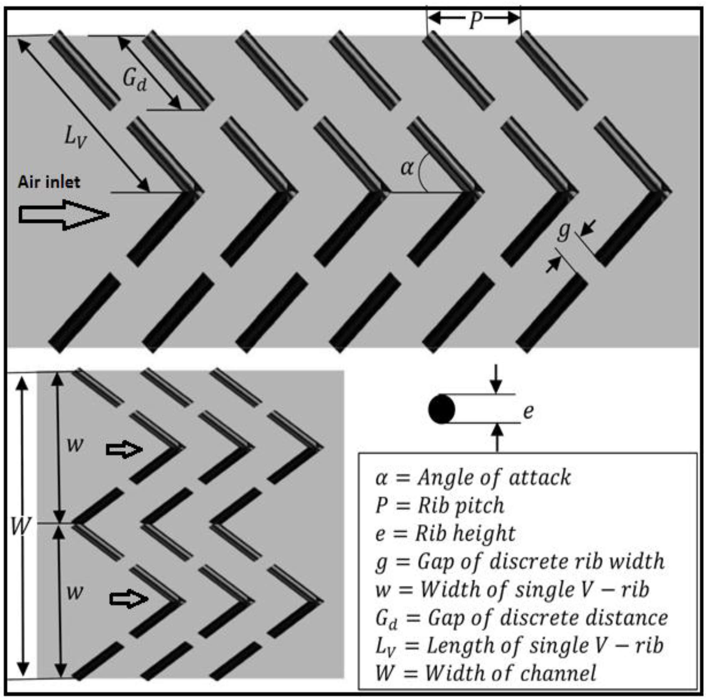
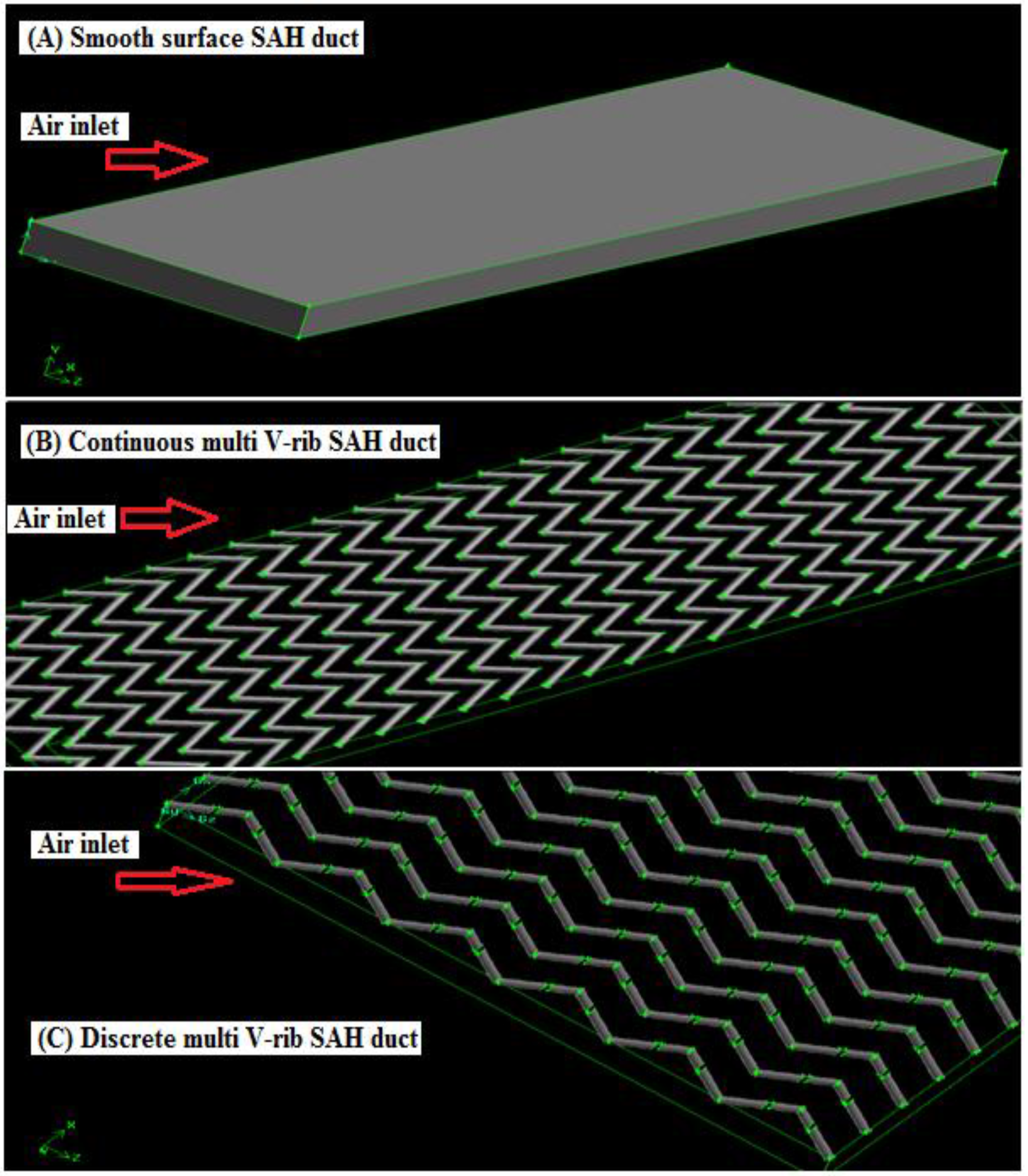
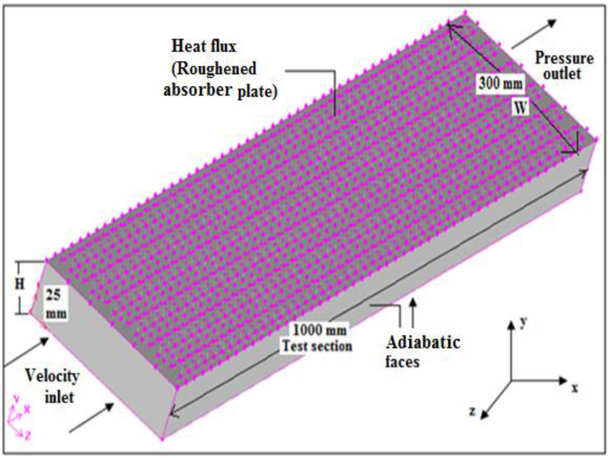
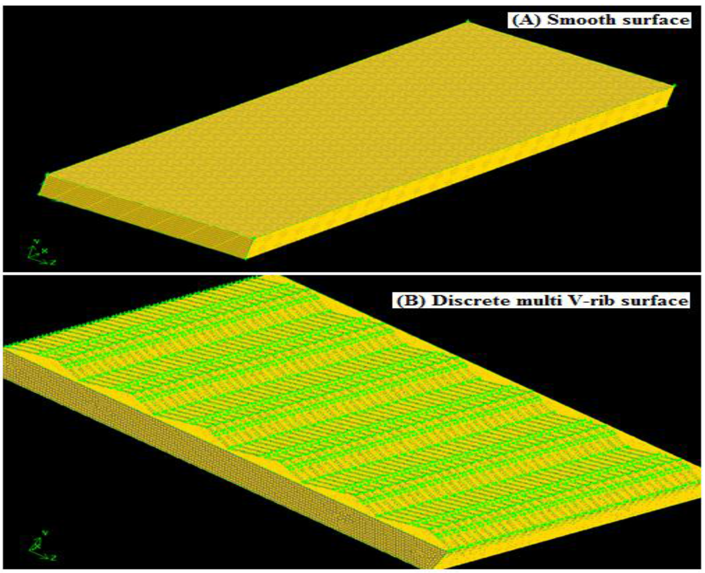
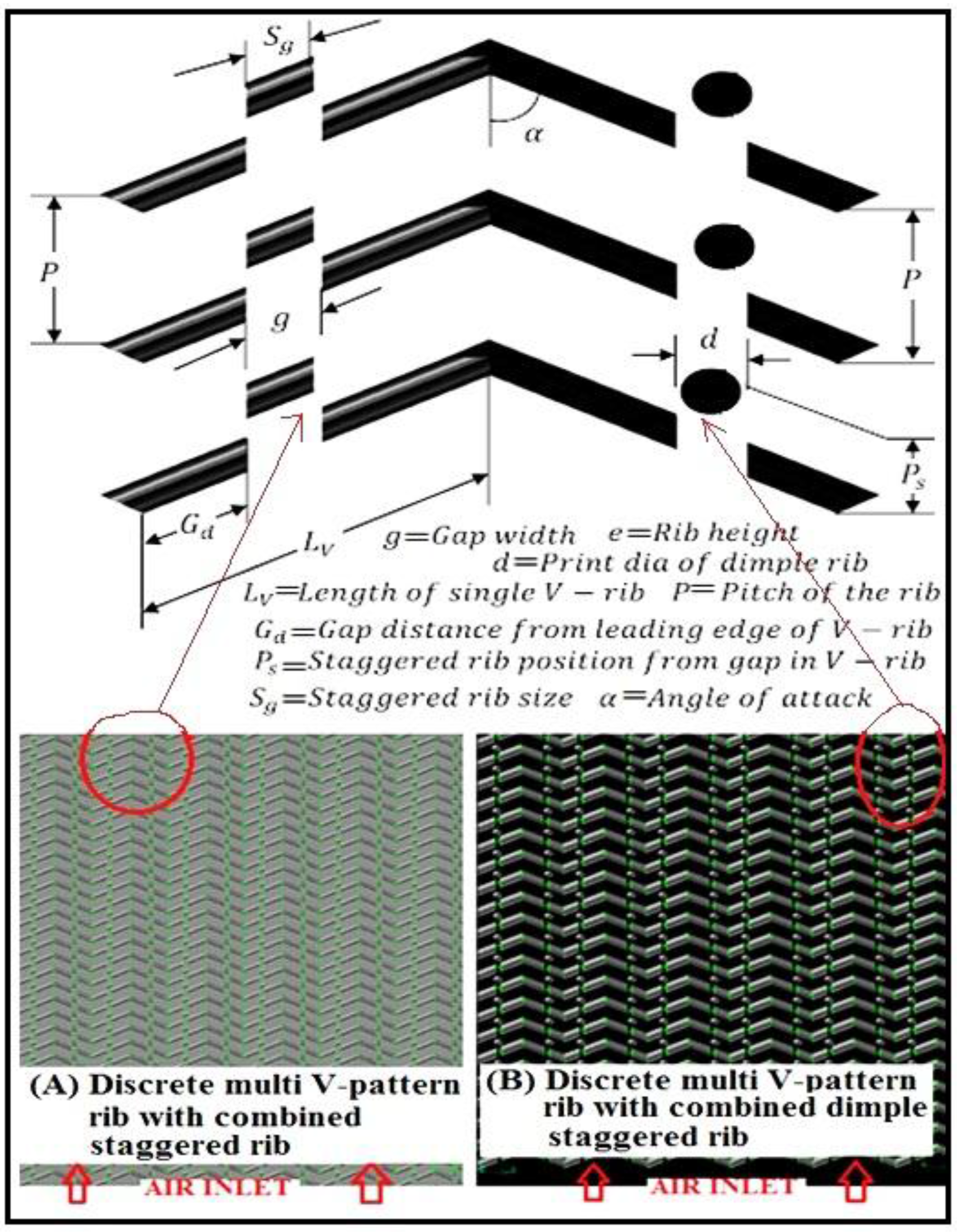
2.1. Computational Geometry

Figure 2 and Figure 3 show the computational domain for the CFD analysis. The SAH channel size is H = 25 mm and W = 300 mm. The rib roughness can be defined by the discrete distance ( G d ) , length of single V-pattern rib ( L v ) , discrete width ( g ) , rib height ( e ) , width of channel ( W ) , width of V-pattern rib ( w ) , and rib pitch ( P ) . These parameters were expressed in dimensionless roughness parameters: relative discrete distance ( G d / L v ) , relative discrete width ( g / e ) , relative rib width ( W / w ) , relative roughness pitch ( P / e ) , relative roughness height ( e / D ) , and angle of attack ( α ) . Roughness parameters were selected such as G d / L v = 0.69 ( G d = 20 mm, L v = 28.87 mm), g / e = 1.0 ( g = 2 mm, e = 2 mm), W / w = 6.0 ( W = 300 mm, w = 50 mm), P / e = 10 ( P = 20 mm, e = 2 mm), e / D = 0.043 ( e = 2 mm, D = 46.15 mm). The flow and roughness parameters are shown in Table 1.

2.2. Governing Equations

The numerical model for fluid flow and heat transfer in a duct was developed under the following assumptions:
  • The flow is steady, fully developed, turbulent and three-dimensional.
  • The thermal conductivity of the duct wall, absorber plate and roughness material are independent of temperature.
  • The duct wall, absorber plate and roughness material are homogeneous and isotropic.
  • The working fluid (air) is assumed to be incompressible for operating range of solar air heaters since variation in density is very less.
  • No-slip boundary condition is assigned to the walls in contact with the fluid in the model.
  • Negligible radiation heat transfer and other heat losses.
The governing equations for the 3-D CFD analysis can be described as follows [31].
Continuity equation:
· ( ρ · υ ) = 0
Momentum equation:
· ( ρ · υ · υ ) = p + · ( μ [ υ + υ T ) 2 3 · υ I ] ) + ρ g
Energy equation:
· ( υ ( ρ E + p ) ) = · ( k e f f T h J + ( μ [ ( υ + υ T ) 2 3 · υ I ] · υ ) )
where k e f f is the effective conductivity.
The RNG k-ε turbulence model is used [31]. In RNG k-ε model, the turbulence kinetic energy ( k ) and its rate of dissipation ( ε ) are obtained from the following transport equations, respectively:
x i ( ρ k u i ) = x j ( α k μ e f f k x j ) + G k + G b ρ ε Y M + S k
x i ( ρ ε u i ) = x j ( α ε μ e f f ε x j ) + C 1 ε ε k ( G k + G 3 ε G b ) C 2 ε ρ ε 2 k R ε + S ε
In these equations G k , S, G b , and Y M represent the production of turbulence kinetic energy, the modulus of the mean rate of strain tensor, the generation of turbulence kinetic energy due to buoyancy for ideal gas and influence of the fluctuating dilatation in compressible turbulence to the overall dissipation rate, respectively: G k   =   μ t S 2 , S = 2 S i j S j i , G b = g i μ t / ρ P r t ρ / x i , Y M = 2 ρ ε M t 2 , where the quantities α k and α ε are the inverse effective Prandtl numbers for k and ε , respectively. S k and S ε are user defined source terms, and R ε = C μ ρ η 1 3 ( 1 η 1 / η 0 ) / 1 + β o η 1 3 ε 2 / k , where η 1 = S . k / ε , C μ = 0.0845, η 0 = 4.38, β o = 0.012. The model constants C 1 ε and C 2 ε in Equation (5) are 1.42 and 1.68, respectively.

2.3. Boundary Conditions

At the inlet of the computational domain, the velocity inlet boundary condition is specified. The initial temperature of fluid is constant at 300 K. The ranges of air inlet velocity are 0.7–7.4 m/s. Reynolds numbers are calculated based on these inlet velocities. A constant heat flux (I = 1000 W / m 2 ) was given on the upper wall, which was reflected to the experimental observations as shown in Figure 4. The lower and other two side walls were assumed to be adiabatic. At the outlet, a pressure outlet boundary condition was given as a constant pressure of 1.013 × 10⁵ Pa .

2.4. Numerical Scheme

The commercial software ANSYS-FLUENT has been used for the simulations of 3-D discrete multi V-pattern rib geometry. The finite volume technique is used in order to solve the continuity, momentum and energy equations over the individual cells in the computational domain. For pressure velocity coupling, SIMPLE scheme is used and second order spatial discretization scheme Least Squares Cell Based is used to solve the 3-D CFD model. Figure 5 shows 3-D discrete multi V-pattern rib geometry and grids. Tetrahedral mesh of different cell and element sizes were generated. The maximum skewness was 0.61 with the total of about 2.0 million cells.

2.5. Grid Independence Test

A grid independence test was used as a solution refinement method. A grid-dependency study was carried out to evaluate the mesh suitability for the turbulent flow through the rib rectangular channel. Before carrying out the detailed investigation on the different multi V-rib shapes for the selected range of R e , a grid independence test was conducted for the rib-roughened SAH duct. Generating the computational grid was done by the preprocessor GAMBIT 2.3.16 software. At the start, coarse meshing was done and outcomes obtained. Mesh was made successively finer by applying gradient adaptation for temperature, pressure, velocity, wall shear stress and turbulence intensity. The entire computational domain has been meshed with a uniform grid with mesh wall elements spacing of y+ ≈ 2.

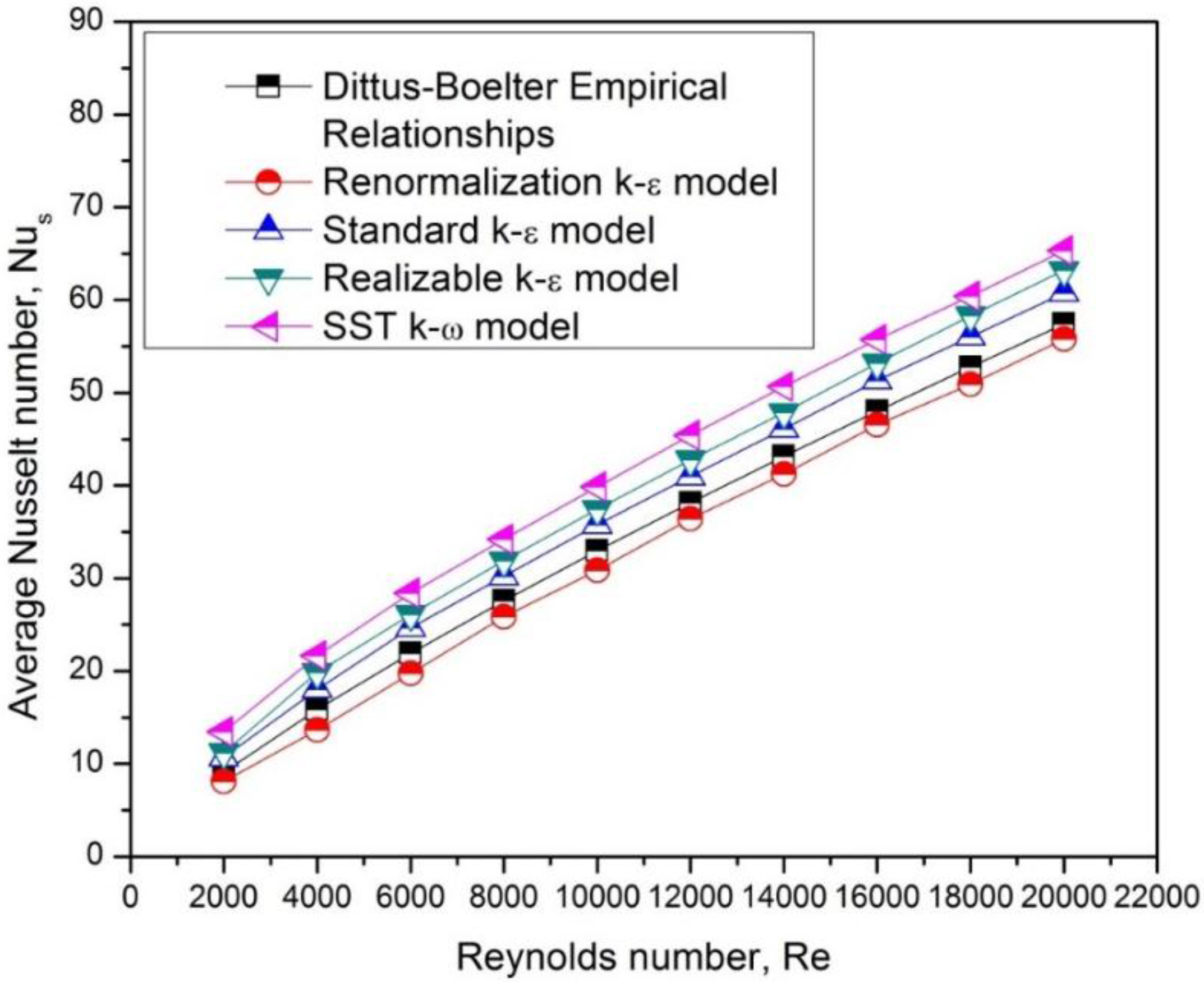
2.6. Model Selection and Validation

The selection and validation of turbulence model are carried out by comparing the N u s calculated by different models (the RNG k - ε , standard k - ε , realizable k - ε , and shear stress transport (SST) k - ω models). Figure 6 shows the variation of N u s with R e for the different models. The results are compared with the Dittus-Boelter empirical relationship [9] for a smooth wall in Equation (6).
N u s = 0.023 R e 0.8 P r 0.4
The results of the RNG k - ε model are in good agreement with the Dittus-Boelter empirical relation. The coefficient of determination ( R 2 ) statistical method was used to determine how well the distribution of two data sets matched [16]. The value of R 2 was more suitable for the RNG model than for the other CFD models as shown in Table 2. The RNG k - ε model was therefore used in this study to simulate the heat transfer and fluid flow in the SAH channel. Similar methodology has been reported by various investigators [20,22,24,25,26,27,28,29,30].

3. Results and Discussion

3.1. Temperature Profile

Figure 7A shows the three-dimensional static temperature distribution of the smooth wall SAH channel. The topmost of the channel was considered as a hot heated plate with a constant heat flux condition. Atmospheric air entered at the rectangular SAH channel and flowed below the heated plate (with a smooth wall) with a uniform stream.
Most of the stream that happens in practical applications is of the overall turbulent nature. In the turbulent region, the velocity of the particles very close to the wall becomes nearly zero. In this region, the fluids have very low kinetic energy. This area is called the laminar or viscous sub-layer. This viscous sub-layer acts as a barrier of heat transfer from a heated surface to a fluid medium. Ribs that were fitted to the base of the heated plate broke and disturbed the laminar sub-layer and created a wavy flow as shown in Figure 7B. The air very close to the wall gets heated due to convection. As an outcome, the temperature of the fluid near the wall was higher and continued to decrease away from the wall up to one third of the height of the SAH channel (Figure 7B).

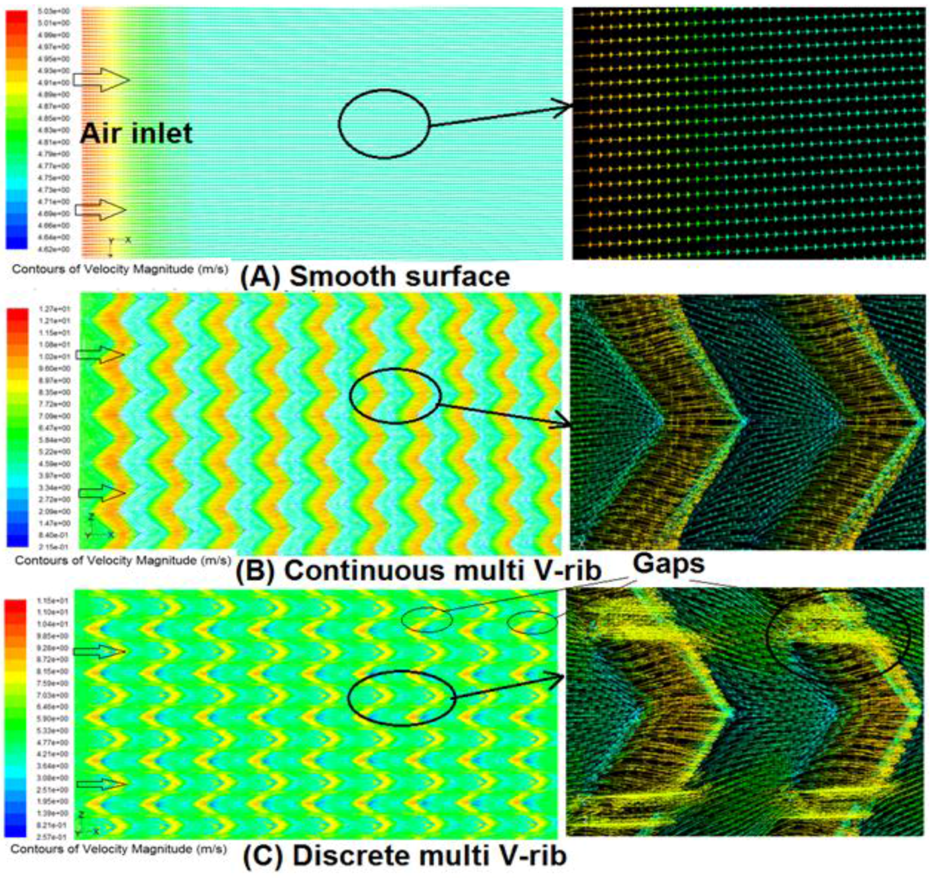
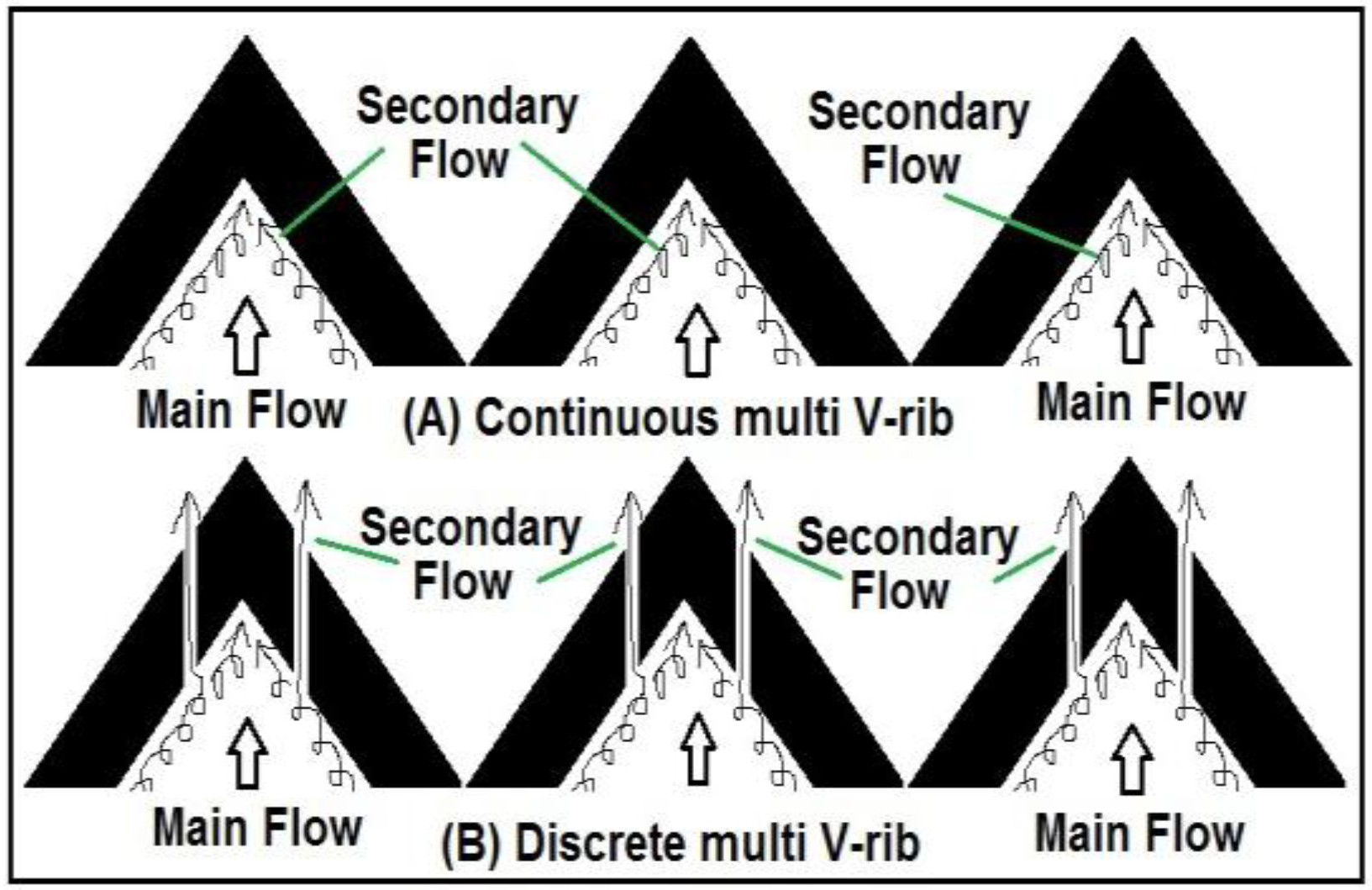
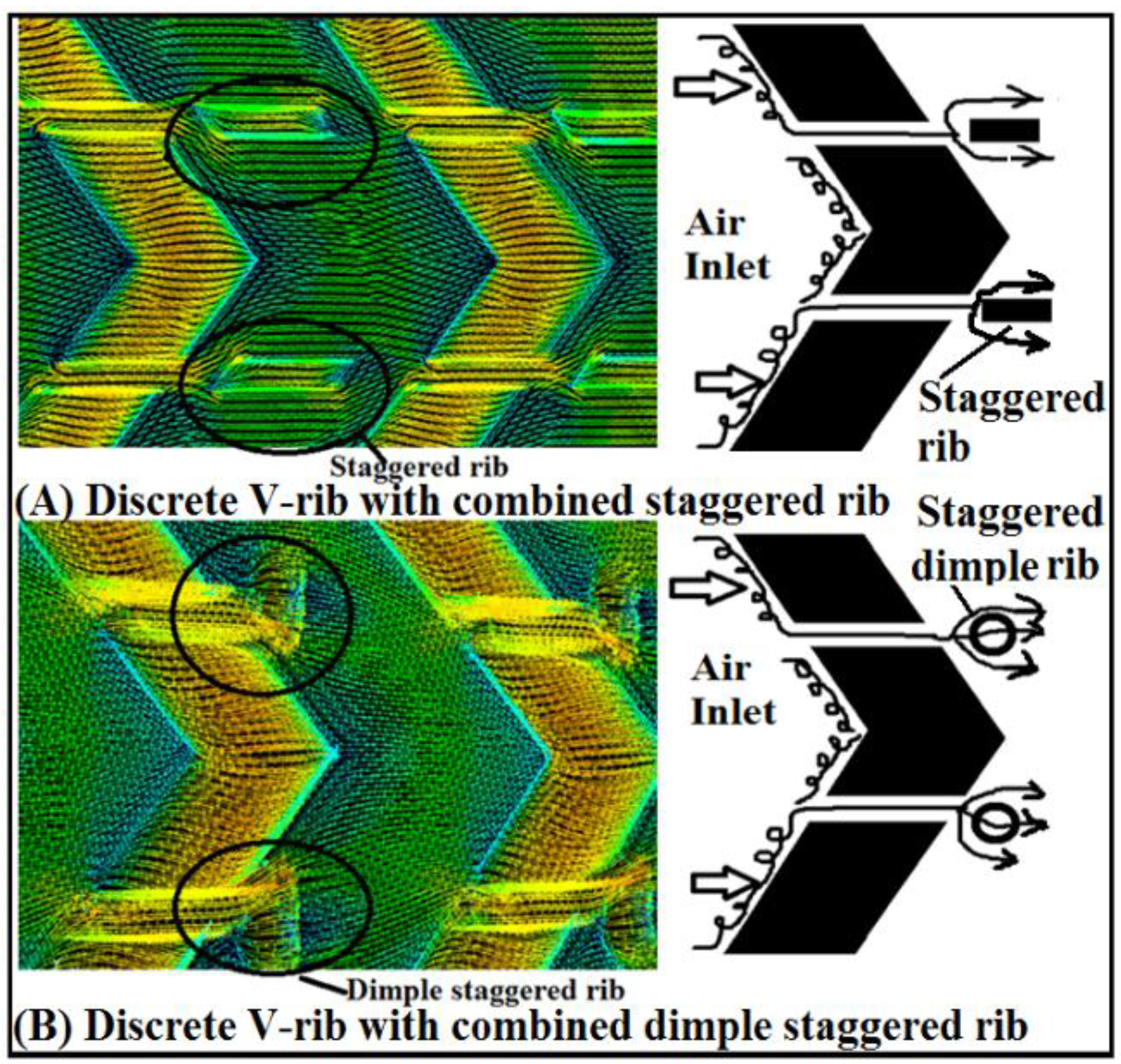
3.2. Velocity Profile

Comparison of the air velocity magnitude in smooth wall channel and multiple V-pattern rib roughened channel arrangement is presented in Figure 8. The air velocity magnitude on the smooth SAH is shown in Figure 8A. Figure 8B shows velocity magnitude on the continuous multi V-pattern rib (with W / w = 6.0, e / D = 0.043, P / e = 10, and α = 60°) roughened SAH. The air velocity magnitude on the discrete multi V-pattern ribs (with G d / L v = 0.69, g / e = 1.0, P / e = 10, e / D = 0.043, W / w = 6.0, and α = 60°) surface is shown in Figure 8C. Continuous multi V-pattern ribs in a SAH channel gives growth to secondary stream vortices along the rib length, which permits the working fluid to move from leading edge to trailing edge. Discrete multi V-pattern rib were shown to perform improved than continuous multi V-pattern ribs, because the discrete multi V-pattern ribs allowed the secondary stream vortices to release along the ribs, join the main stream, and accelerate as presented in the Figure 8. The introduction of a discrete multi V-rib allows the release of the secondary flow and main flow through the discrete rib. The main flow is a developed flow with thicker boundary layer, and due to the presence of viscous sublayer, it leads to a low amount of heat transfer. In fact, the ribs are introduced to break this retarded flow and let is reattach again with the surface to enhance the heat transfer. This increases the heat transfer through the discrete width area behind the rib.

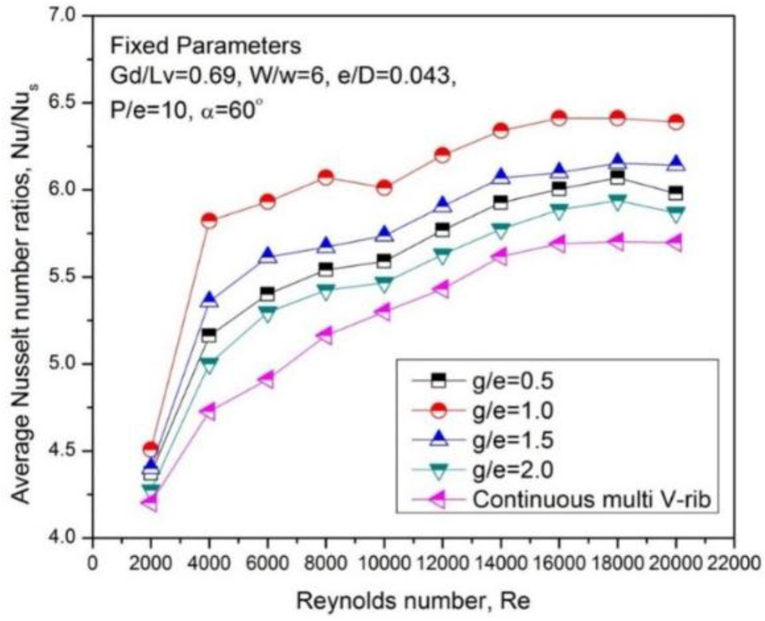
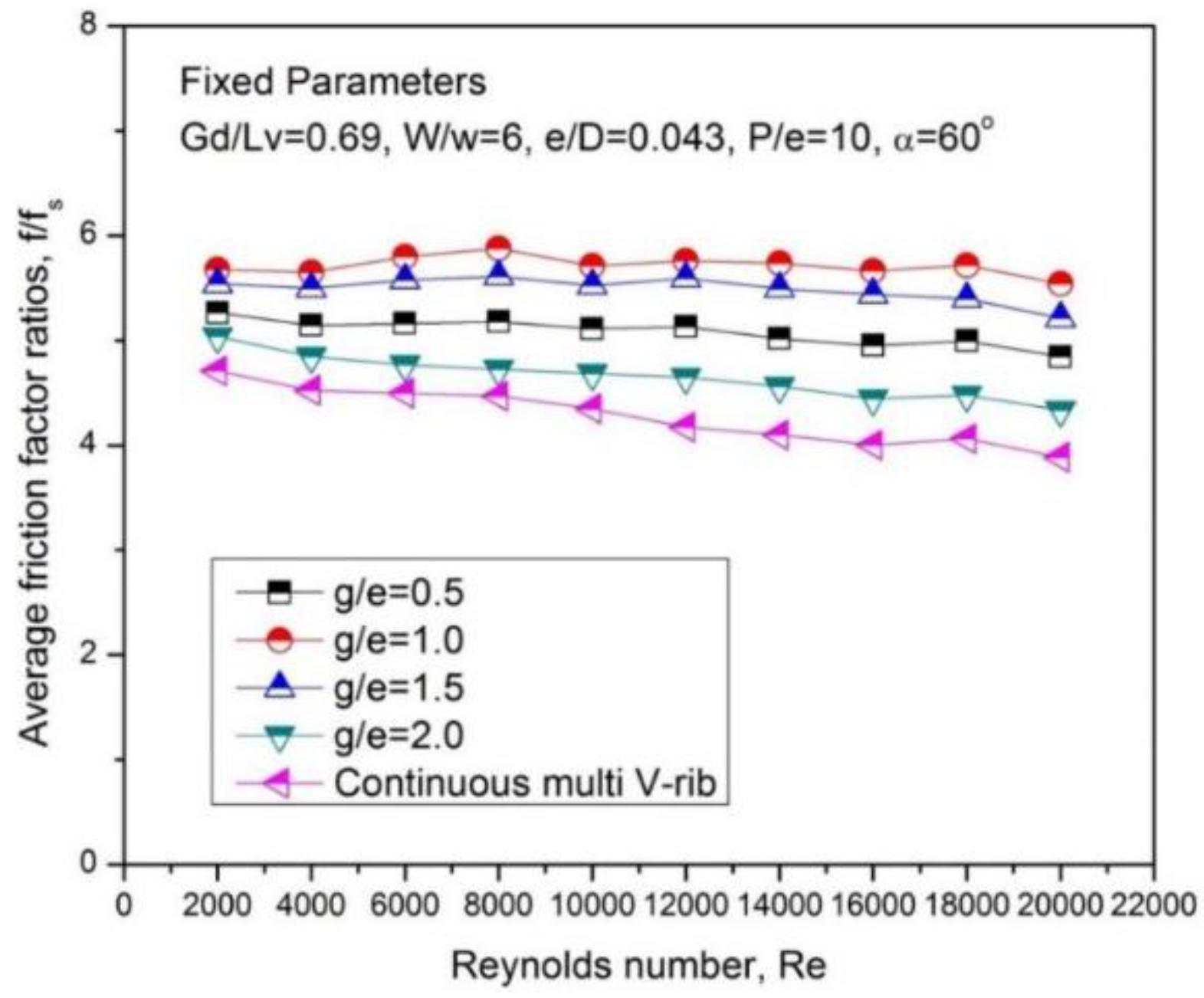
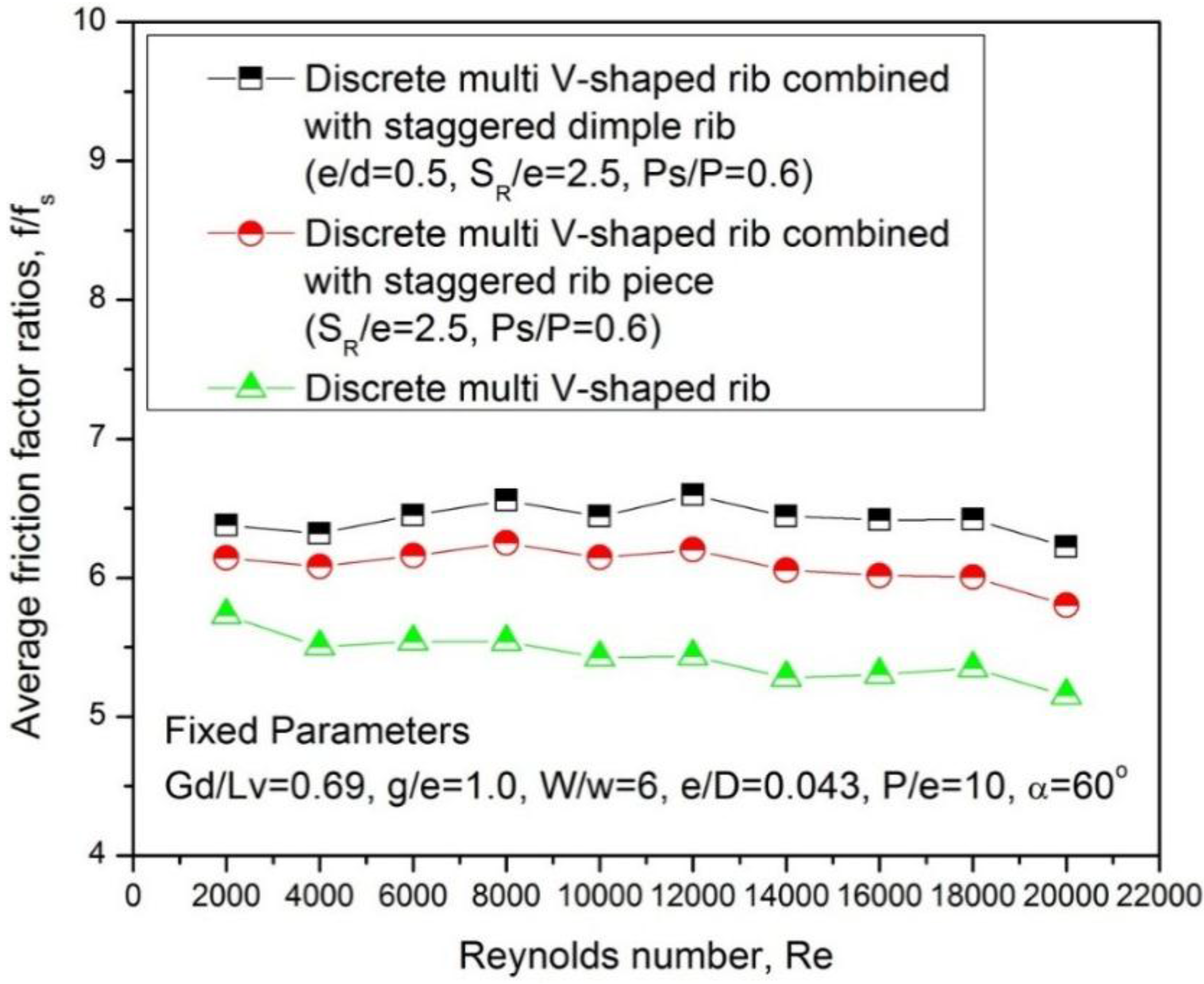
3.3. Heat Transfer and Friction Factor

The effect of discrete width and its location on an SAH channel’s heat transfer and fluid flow behaviors was explored for artificial roughening with multi V-pattern rib. The values of the average N u / N u s and the average f / f s of discrete and continuous multi V-rib roughened SAH channel were compared, under similar numerical condition. The heat transfer characteristics of the discrete multi V-pattern rib-roughened rectangular SAH channel were calculated on the basis of data collected for various flow and roughness parameters. The effect of g / e on the average N u / N u s for fixed values of the other roughness parameters ( G d / L v = 0.69, W / w = 6.0, P / e = 10, e / D = 0.043, and α = 60°) is shown in Figure 9. Average N u / N u s increased with increasing R e values for both the continuous and discrete multi V-pattern rib-roughened SAH channel.
It could also be seen that for any R e the average N u / N u s was higher for a discrete multi V-pattern rib than for a rib without a discrete multi V-pattern rib. The average N u / N u s increased with increasing g / e from 0.5 to 1.0 and reached a maximum at a discrete width of 1.0. Hence, it could be logical that the rise in g/e beyond 1.0 decreases the stream velocities through the discrete and also decreases the local turbulence. At the similar time, a discrete width that is too low will also not permit sufficient quantity of secondary stream fluid to permit through and therefore the turbulence level will remain low. Thus, to achieve enhanced heat transfer, the width of the discrete rib should be such that it can increase the velocity of the air passing through it to generate the local turbulence [18].
The average N u / N u s for the continuous multi V-pattern rib lies in the range of 4.17–6.4 for the range of Re of the present investigation. The average N u / N u s for the discrete multi V-pattern rib lies in the range of 4.25–6.4 for the range of Re of the current investigation. A continuous multi V-pattern rib in an SAH rectangular channel gave rise to secondary stream along the rib length, which permitted the working fluid to travel from the rib’s leading to trailing edge. The air stream along the rib was slowly heated and the boundary layer grew thicker. The air stream turned downward from the sidewall and completed the recirculation loop (Figure 10). As shown by previous research, V-pattern ribs benefit the creation of two leading ends, a single trailing end, and two secondary flow cells, which improve mixing and hence improve the heat transfer rate [11]. The introduction of discrete multi V-pattern ribs resulted in the release of the secondary stream cells and their mixing with the main stream. The main stream was a developed stream with a thicker boundary layer. It led to a low amount of heat transfer because of the presence of a laminar sub-layer. The ribs were in fact introduced to disrupt this retarded stream and let it re-attach to the wall to enhance the heat transfer (Figure 10).
The variation of average f / f s with R e for different values of g / e and fixed values of other rib parameters as G d / L v = 0.69, W / w = 6.0, e / D = 0.043, P / e = 10 and α = 60° has been shown in Figure 11. It has been observed that for all values of g / e , f / f s decreases with increase in R e . Figure 11 shows that at all R e , the f / f s increases as g / e is increased from 0.5 to 1.0 and decreases as g / e is increased further.
The air flowing through the gap creates turbulence at the downstream side of the gap. The average f / f s for a g / e of 2.0 was close to that observed for the continuous multi V-pattern rib, which could have been because of the very weak stream through this large discrete (2.0). Addition of relative gap width in the ribs induces recirculation loops, which are responsible for higher turbulence and hence higher pressure losses. Strength of secondary flow is weakened in case of g / e of 2.0 as compared to g / e of 0.5, 1.0 and 1.5 hence the friction loss is lower than in other cases. The range of the average f / f s was 5.45–5.67 for the investigated range of R e and discrete width.

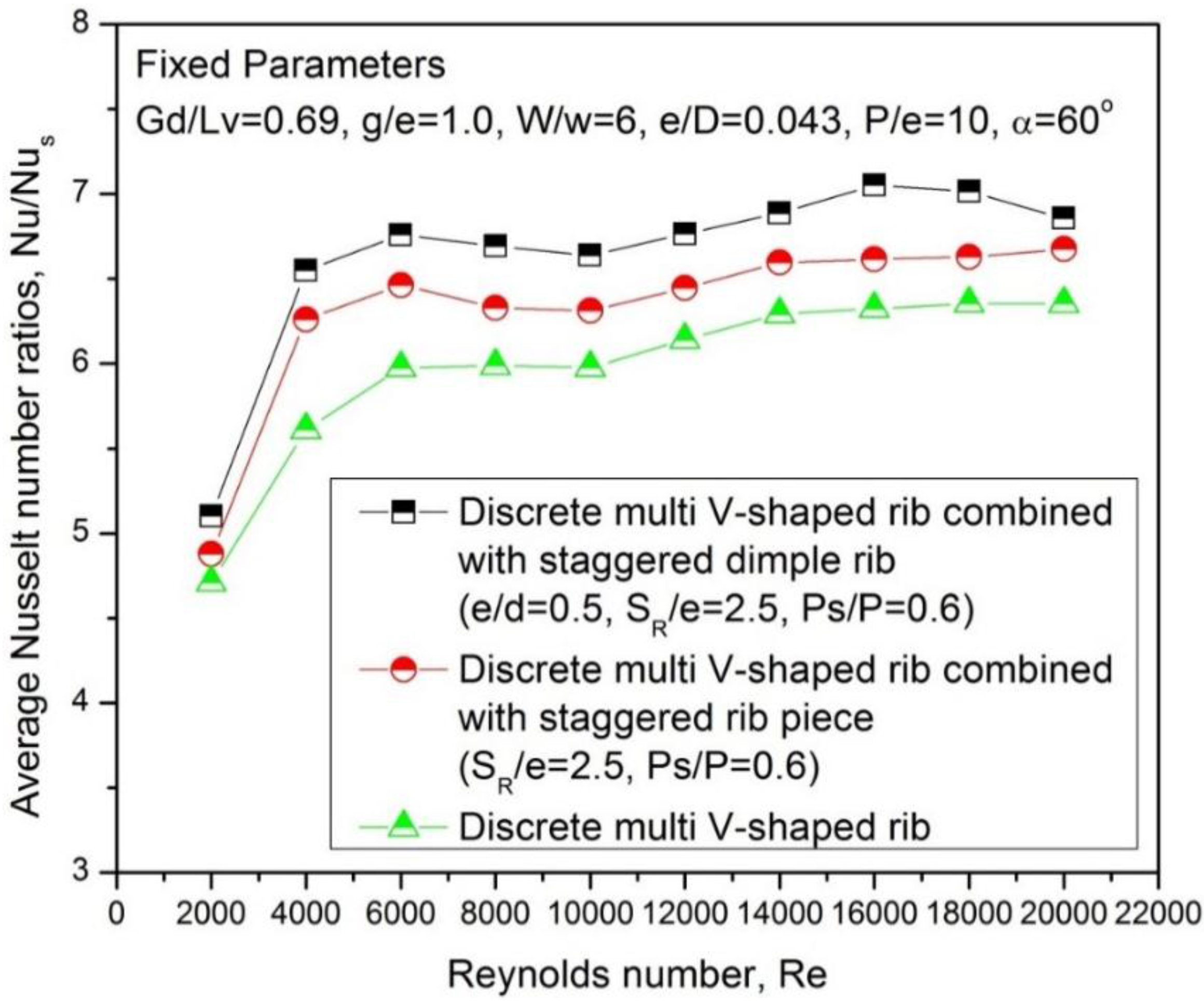
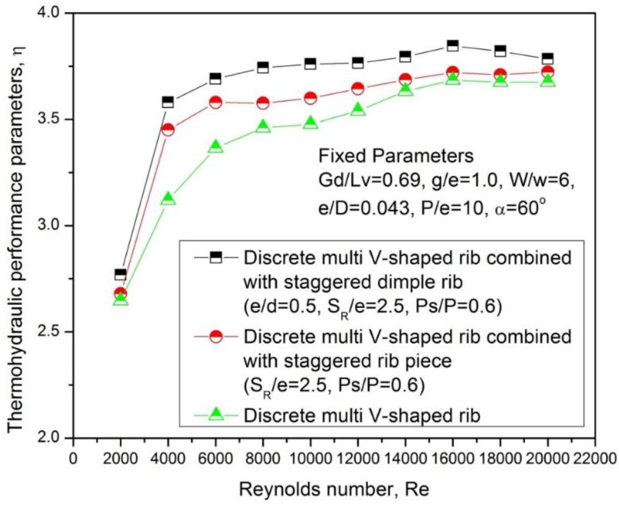
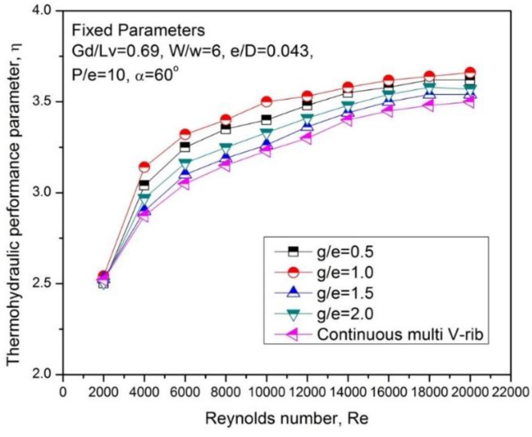
3.4. Thermo-Hydraulic Performance

The CFD results indicated that average N u / N u s increased with increasing g / e , and average f / f s also increased. The SAH collector efficiency therefore depended on these two parameters. The SAH collector’s performance enhancement owing to the artificial roughness is usually estimated on the basis of the thermo-hydraulic performance parameter, which includes both the thermal and hydraulic concerns. The thermo-hydraulic performance parameter (Equation (7)) was defined as the overall enhancement ratio and expressed as follows [28,29,30]:
η = ( N u / N u s ) / ( f / f s ) 0.33
It is evident that only a heated wall roughness that yields a performance parameter value greater than unity is useful. The higher the value of this parameter, the better the solar air channel performance. The plot of thermo-hydraulic performance parameter as a function of R e at different values of g / e is shown in Figure 12. It is seen that thermo-hydraulic performance increases with an increase in the g/e up to about 1.0, beyond which it decreases with increase in the g/e. The thermo-hydraulic value is the maximum for the g/e of 1.0 and the minimum for the g/e of 2.0 for the range of investigation. Compared with continuous multi V-shaped rib SAH duct, the thermal hydraulic performance of the discrete multi V-shaped SAH duct is increased by about 8.56%.
This basic reason of creating a discrete in the multi V-rib is that, the discrete flow promotes local turbulence and flow mixing along the discrete flow region while the rib induced secondary flow is maintained in the duct. Due to this, the increase in g/e beyond 1.0 reduces the flow velocities through the discrete and also reduces the local turbulence. At the same time too small a discrete width will also not allow sufficient amount of secondary flow fluid to pass through and hence the turbulence level will remain low. It increased with increases in the g / e up to about 1.0 and then decreased with further increases in the g / e at all R e values. It therefore attained a maximum at g / e of about 1.0.

4. Shape Optimization

The heat transfer and fluid flow examination was carried out by using CFD software. In the current analysis the arrangement of roughness elements in the form of discrete multi V-pattern with combined staggered rib and discrete multi V-pattern with combined dimple staggered rib on the internal side of the heated plate has been careful. For shape optimization the explanation domain used for the CFD simulation is shown in Figure 13. Roughness parameters were selected such as G d / L v = 0.69 W / w = 6.0, P / e = 8.0, e / D = 0.043, α = 60°, S R / e = 2.5, P s / P = 0.6 and e / d = 0.5 based on the optimal values of these parameters stated in the literature [1,2,6,7,8,9,10,11,12,13,14,15,16,17,18,19,20,21,22,23]. Relative discrete width ( g / e ) is selected as 1.0 based on optimal value of this parameter in current CFD study. CFD study was conducted to understand the effect on heat transfer and friction factor of the roughened SAH channel as a function of R e . Figure 14 shows the average N u / N u s profile in order to estimate the heat transfer rate enhancement for the discrete multi V-pattern rib, discrete multi V-pattern rib with combined staggered rib and discrete multi V-pattern with dimple staggered rib. Figure 14 clearly shows the discrete multiple V-pattern rib with dimple staggered rib roughness enhanced the performance compared to the discrete multi V-pattern rib and discrete multi V-with staggered rib. The discrete multi V-pattern rib with dimple staggered rib is superior to the other multi V-pattern rib roughness. When a discrete rib is placed near the apex of the V-pattern rib, it releases secondary cells in the region of low N u . The high-mass-flow-rate jet from the secondary cells approaches the dimple staggered rib and creates supplementary turbulence as an outcome of the flow reattachment and separation and reattachment as shown in Figure 15.
Figure 16 shows the average f / f s profile in order to estimate the heat transfer rate enhancement for the discrete multi V-pattern rib, discrete multi V-pattern rib combined with staggered rib piece and discrete multi V-pattern rib combined with dimple staggered rib. Figure 16 clearly shows that the discrete multi V-pattern rib, combined with the dimple staggered rib roughness, has a higher value of average f / f s as compared to the discrete multi V-pattern rib and discrete multi V-shape rib combined with staggered ribs. This reflects how the secondary flow exerts a measurable impact and disturbs the axial flow profile, which increases the friction coefficient in non-circular channels [9,11,12].
The thermo-hydraulic parameter has been compared using the CFD results of average N u / N u s and average f / f s with discrete multi V-pattern rib, discrete multi V-pattern rib combined with staggered ribs and discrete multi V-pattern rib combined with dimple staggered ribs as depicted in Figure 17. It is observed that the discrete multi V-pattern rib combined with dimple staggered ribs shows better performance compared to the other rib shapes. Compared with discrete multi V-pattern rib and discrete multi V-pattern rib combined with staggered ribs SAH duct, the overall thermal performance of discrete multi V-pattern rib combined with dimple staggered ribs increased by about 7%. Table 3 shows the comparison of the previous results for the thermo-hydraulic performance parameter.

5. Conclusions

In this article, a CFD-based analysis was performed to analyze heat transfer and fluid flow characteristics in SAH channels with discrete multi V-pattern ribs. Substantial performance augmentation by using artificial discrete multi V-shape in anSAH duct has been achieved, and the augmentation is a strong function of relative discrete width. This reflects the generation of turbulence near the heat transfer surface on account of flow separation and flow acceleration through the discrete ribs. The values of average N u / N u s increased with increasing R e for all combinations of g / e . The highest values of the average N u / N u s and average f / f s correspond to a g / e of 1.0. A thermo-hydraulic performance parameter with a maximum value of 3.6 is found for the roughness geometry corresponding to g / e of 1.0. A significant enhancement in the thermo-hydraulic performance using staggered arrangement in discrete multi V-pattern ribs has been identified. The value of the thermo-hydraulic performance parameter varies between 2.74 and 3.82 for the range of parameters investigated in the study. A discrete multi V-pattern rib combined with dimple staggered rib roughness ( S R e = 2.5 , P s P = 0.6 ,   G d L v = 0.69 , g e = 1.0 , W w = 6.0 , P e = 10 , e D = 0.043 , e d = 0.5   a n d   α = 60 ° ) also provides better overall thermal performance in comparison with other rib shapes SAH channel.

Acknowledgments

This research was supported by the Engineering Development Research Center (Grant No. 10000990) by the Ministry of Trade, Industry & Energy.

Author Contributions

Authors made equal contribution and efforts on writing the manuscript.

Conflicts of Interest

The authors declare no conflict of interest.

Nomenclature

d Print diameter of dimple, ( m )
D Hydraulic diameter of channel, ( m )
d / W Relative discrete position
e Rib height, ( m )
e / D Relative roughness height
e / d Ratio of dimple depth to print diameter
E Energy, ( J )
f s Friction factor of smooth wall
f Friction factor of roughened wall
g Discrete or gap width, ( m )
g / e Relative discrete width
G d Discrete distance for rib, ( m )
G d / L v Relative discrete distance
H Depth of channel, ( m )
I Solar intensity, ( W / m 2 )
k Turbulent kinetic energy, ( m 2 / s 2 )
l Length of metal grit rib, (m)
L v Length of a single V-shaped rib, ( m )
m Mass flow rate, ( kg / s )
M t Turbulent Mach number
N u Nusselt number of roughened channel
N u s Nusselt number of smooth channel
P Pitch of the rib, ( m )
P / e Relative rib pitch
P S Distance from the discrete or discrete
p Pressure, ( Pa )
P r Prandtl number
P r t Turbulent Prandtl number
P s / P Relative staggered rib position
R e Reynolds number
R 2 Coefficient of determination
s Distance of metal grit rib parallel to direction of stream, ( m )
S R Staggered rib size, ( m )
S R / e Relative discrete position or distance
u i Velocity in x i -direction, ( m / s )
v Overall velocity vector, ( m / s )
W Width of channel, ( m )
w Width of a single V-shaped rib, ( m )
W / w Relative rib width
W / H Channel aspect ratio
y + Dimensionless distance from walls
Greek Symbols
α Angle of attack, degree
β Thermal expansion coefficient, 1 / K
µDynamic viscosity, ( Ns / m 2 )
µtTurbulent viscosity, ( Ns / m 2 )
ρ Density, ( kg / m 3 )
η Thermo-hydraulic performance parameter
η O ,   β O Model constant
ε Turbulent kinetic energy dissipation rate, ( m 2 / s 3 )
σ k Prandtl number for k
σ ε Prandtl number for ε
C μ , C ε 1 ,   C ε 2 RNG k - ε model constant
Subscript
CFD Computational fluid dynamics
SAH Solar air heater

References

  1. Kumar, A.; Kim, M.-H. Thermohydraulic performance of rectangular ducts with different multiple V-rib roughness shapes: A comprehensive review and comparative study. Renew. Sustain. Energy Rev. 2016, 54, 635–652. [Google Scholar] [CrossRef]
  2. Kumar, A.; Saini, R.P.; Saini, J.S. A review of thermo-hydraulic performance of artificially roughened solar air heaters. Renew. Sustain. Energy Rev. 2014, 37, 100–122. [Google Scholar] [CrossRef]
  3. Duffie, J.A.; Beckman, W.A. Solar Engineering Thermal Processes; John Wiley: New York, NY, USA, 1991. [Google Scholar]
  4. Bhuiyan, A.A.; Amin, M.R.; Karim, M.R.; Islam, A.K.M.S. Plate fin and tube heat exchanger modeling: Effects of performance parameters for turbulent flow regime. Int. J. Autom. Mech. Eng. 2014, 9, 1768–1781. [Google Scholar]
  5. Karim, M.R.; Akhande, M.A.R. Study of a hybrid photovoltaic thermal solar system using different ribbed surfaces opposite to absorber plate. J. Eng. Technol. 2011, 9, 17–30. [Google Scholar]
  6. Kumar, A.; Saini, R.P.; Saini, J.S. Heat and fluid flow characteristics of roughened solar air heater ducts—A review. Renew. Energy 2012, 47, 77–94. [Google Scholar] [CrossRef]
  7. Prasad, K.; Mullick, S.C. Heat transfer characteristics of a solar air heater duct used for drying purposes. Appl. Energy 1983, 13, 83–93. [Google Scholar] [CrossRef]
  8. Prasad, B.N.; Saini, J.S. Effect of artificial roughness on heat transfer and friction factor in a solar air heater. Sol. Energy 1988, 41, 555–560. [Google Scholar] [CrossRef]
  9. Han, J.C.; Zhang, Y.M.; Lee, C.P. Augmented heat transfer in square channels with parallel crossed and V-shaped angled ribs. J. Heat Trans. 1991, 113, 590–596. [Google Scholar] [CrossRef]
  10. Kukreja, R.T.; Lau, S.C.; McMillian, R.D. Local Heat and Mass transfer distribution in a square channel with full and V-shaped rib. Int. J. Heat Mass Trans. 1993, 36, 2013–2020. [Google Scholar] [CrossRef]
  11. Taslim, M.E.; Li, T.; Krecher, D.M. Experimental heat transfer and friction in channel roughened with angled, v-shaped and discrete ribs on two opposite walls. J. Turbomach. 1996, 118, 20–28. [Google Scholar] [CrossRef]
  12. Karwa, R.K. Experimental studies of augmented heat transfer and friction in asymmetrically heated rectangular ducts with ribs on heated wall in transverse, inclined, v-continuous and v-discrete pattern. Int. Commun. Heat Mass Trans. 2003, 30, 241–250. [Google Scholar] [CrossRef]
  13. Wang, L.; Sunden, B. An experimental investigation of heat transfer and fluid flow in a rectangular duct with broken v-shaped ribs. Exp. Heat Trans. 2004, 17, 243–359. [Google Scholar] [CrossRef]
  14. Wright, L.M.; Fu, W.L.; Han, J.C. Thermal performance of angled V-shaped and W-shaped rib turbulators in rotating rectangular cooling channels (AR = 4:1). J. Turbomach. 2004, 126, 604–614. [Google Scholar] [CrossRef]
  15. Maithani, R.; Saini, J.S. Heat transfer and friction factor correlations for a solar air heater duct roughened artificially with V-ribs with symmetrical gaps. Exp. Ther. Fluid Sci. 2016, 70, 220–227. [Google Scholar] [CrossRef]
  16. Hans, V.S.; Saini, R.P.; Saini, J.S. Heat transfer and friction correlations for a solar air heater duct roughened artificially with multiple v-ribs. Sol. Energy 2010, 84, 898–911. [Google Scholar] [CrossRef]
  17. Saini, S.K.; Saini, R.P. Development of correlations for Nusselt number and friction factor for solar air heater with roughened duct having arc-shaped wire as artificial roughness. Solar Energy 2008, 82, 1118–1130. [Google Scholar] [CrossRef]
  18. Bhushan, B.; Singh, R. Nusselt number and friction factor correlations for solar air heater duct having artificially roughened heated plate. Solar Energy 2011, 85, 1109–1118. [Google Scholar] [CrossRef]
  19. Kumar, A.; Saini, R.P.; Saini, J.S. Development of correlations for Nusselt number and friction factor for solar air heater with roughened duct having multi V-shaped with gap rib as artificial roughness. Renew. Energy 2013, 58, 151–163. [Google Scholar] [CrossRef]
  20. Anil, S.Y.; Bhagoria, J.L. A CFD (computational fluid dynamics) based heat transfer and fluid flow analysis of a solar air heater provided with circular transverse wire rib roughness on the heated plate. Energy 2013, 55, 1127–1142. [Google Scholar]
  21. Chaube, A.; Sahoo, P.K.; Solanki, S.C. Analysis of heat transfer augmentation and flow characteristics of a solar air heater. Renew. Energy 2006, 31, 317–331. [Google Scholar] [CrossRef]
  22. Kumar, S.; Saini, R.P. CFD based performance analysis of a solar air heater duct provided with artificial roughness. Renew. Energy 2009, 34, 1285–1291. [Google Scholar] [CrossRef]
  23. Gandhi, B.K.; Singh, K.M. Experimental and numerical investigations on flow through wedge shape rib roughened duct. J. Inst. Eng. (India) Mech. Eng. Div. 2010, 90, 13–18. [Google Scholar]
  24. Sharma, A.K.; Thakur, N.S. CFD based fluid flow and heat transfer analysis of a v-shaped roughened surface solar air heater. Int. J. Eng. Sci. Technol. 2012, 4, 2115–2121. [Google Scholar]
  25. Karmare, S.V.; Tikekar, A.N. Analysis of fluid flow and heat transfer in a grit roughened surface solar air heater using CFD. Sol. Energy 2010, 84, 409–417. [Google Scholar] [CrossRef]
  26. Singh, S.; Singh, B.; Hans, V.S.; Gill, R.S. CFD (computational fluid dynamics) investigation on Nusselt number and friction factor of solar air heater duct roughened with non-uniform cross section transverse rib. Energy 2015, 84, 509–517. [Google Scholar] [CrossRef]
  27. Kumar, A.; Kim, M.-H. Effect of roughness width ratios in discrete multi V-rib with staggered rib roughness on overall thermal performance of solar air channel. Solar Energy 2015, 119, 399–414. [Google Scholar] [CrossRef]
  28. Kumar, A.; Kim, M.-H. Convective heat transfer enhancement in solar air channels. Appl. Ther. Eng. 2015, 89, 239–261. [Google Scholar] [CrossRef]
  29. Kumar, A.; Kim, M.-H. Numerical optimization of solar air heaters with different roughness shapes on the heated plate-technical note. Energy 2014, 72, 731–738. [Google Scholar] [CrossRef]
  30. Kumar, A.; Kim, M.-H. Heat transfer and fluid flow characteristics in air duct with various V-pattern rib roughness on the heated plate: A comparative study. Energy 2016, 103, 75–85. [Google Scholar] [CrossRef]
  31. Fluent Inc. Fluent 6.3 User’s Guide 2006; Fluent Inc.: Lebanon, NH, USA, 2006. [Google Scholar]
Figure 1. Schematic of a simple solar air heater.
Energies 09 00415 g001
Figure 2. Discrete multi V-pattern rib roughness geometry.
Energies 09 00415 g002
Figure 3. Roughness elements: (A) Smooth SAH channel; (B) Continuous multi V-pattern rib SAH channel; (C) Discrete multi V-pattern rib SAH channel.
Energies 09 00415 g003
Figure 4. Boundary conditions.
Energies 09 00415 g004
Figure 5. Grid systems.
Energies 09 00415 g005
Figure 6. N u S with variation of Reynolds numbers.
Energies 09 00415 g006
Figure 7. Temperature profile. (A) Smooth surface SAH channel; (B) Rib surface SAH channel with Re = 10,000.
Energies 09 00415 g007
Figure 8. Velocity profile. (A) Smooth surface SAH channel; (B) Continuous multi V-pattern rib; (C) Discrete multi V-pattern rib with R e = 10,000.
Energies 09 00415 g008
Figure 9. Effect of discrete width on average N u / N u S .
Energies 09 00415 g009
Figure 10. Flow pattern of secondary flow for continuous multi V-pattern rib (A); and discrete multi V-pattern rib (B).
Energies 09 00415 g010
Figure 11. Effect of discrete width ratios on friction factors.
Energies 09 00415 g011
Figure 12. Effect of discrete width ratios on thermal hydraulic performance.
Energies 09 00415 g012
Figure 13. Discrete multi V-pattern with staggered rib. (A) Staggered rib; (B) Dimple staggered rib.
Energies 09 00415 g013
Figure 14. Effect of various discrete multi V-pattern ribs on Nusselt numbers.
Energies 09 00415 g014
Figure 15. Flow pattern (A) Discrete V-pattern rib with combined staggered rib; (B) Discrete V-pattern rib with combined dimple staggered rib.
Energies 09 00415 g015
Figure 16. Effect of various discrete multi V-pattern ribs on average f / f S .
Energies 09 00415 g016
Figure 17. Effect of various discrete multi V-pattern ribs on thermo-hydraulic performance.
Energies 09 00415 g017
Table 1. Values of flow and roughness parameters.
Flow and Rib ParametersRanges
R e 2000–20,000
G d / L v 0.69
g / e 0.5–2.0
W / w 6.0
e / D 0.043
P / e 10
Α 60°
Table 2. Comparison coefficient of determination ( R 2 ) values of various CFD models.
ModelCoefficient of Determination ( R 2 )
Shear Stress Transport (SST) k0.994
Realizable k0.995
Standard k0.996
Renormalization k0.998
Table 3. Comparison of thermo-hydraulic performance with previous investigation.
Rib ShapesParametersExperimental/NUMERICAL Resultsη
Energies 09 00415 i001
Transverse rib
e/D = 0.021–0.034, P/e = 10–20, Re = 5000–50,000Experimental results Prasad and Saini [8]1.66
Energies 09 00415 i002
Transverse rib
e/D = 0.022–0.0424, P/e = 7.16–35.72, Re = 3800–18,000Numerical results Yadav et al. [20]1.62
Energies 09 00415 i003
Angled rib
e/D = 0.019–0.054, P/e = 10, α = 45°–90°, Re = 3000–18,000Experimental results Kumar et al. [2]1.79
Energies 09 00415 i004
Inclined with discrete rib
e/D = 0.038, P/e = 10, d/W = 0.167–0.668, g/e = 0.5–2.0, α = 60°, Re = 3000–18,000Experimental results Kumar et al. [2]1.87
Energies 09 00415 i005
Arc shaped rib
e/D = 0.029–0.0426, P/e = 10, α = 30°–60°, Re = 6000–18,000Numerical results Kumar and Saini [22]1.77
Energies 09 00415 i006
V-pattern rib
e/D = 0.02–0.034, P/e = 10, α = 30°–75°, Re = 2500–18,000Experimental results Taslim et al. [11]2.19
Energies 09 00415 i007
Single V-pattern rib with discrete rib
e/D = 0.015–0.043, P/e = 4.0–12, d/W = 0.2–0.8, g/e = 0.5–2.0, α = 30°–75°, Re = 3000–15,000Experimental results Kumar and Kim [2]2.63
Energies 09 00415 i008
Single discrete V-shaped with staggered rib piece
e/D = 0.043, P/e = 10, SR/e = 0.2–0.8, Ps/P = 0.2–0.8, g/e = 1.0, α = 60°, Re = 3000–17,000Experimental results Kumar et al. [2]2.87
Energies 09 00415 i009
Arc shaped rib
e/D = 0.021–0.036, P/e = 10–20, α = 45°–75°, Re = 3600–18,000Experimental results Kumar et al. [2]2.12
Energies 09 00415 i010
Metal grit rib
e/D = 0.044, P/e = 17.5, α = 60°, l/s = 1.72, Re = 3600–17,000Numerical results Karmare and Tikekar [25]2.10
Energies 09 00415 i011
Discrete W-pattern rib
e/D = 0.0168–0.338, P/e = 10, α = 30°–75°, Re = 3000–15,000Experimental results Kumar et al. [2]2.32
Energies 09 00415 i012
Continuous multi V-pattern rib
e/D = 0.019–0.043, P/e = 8–12, W/w = 1–10, α = 30°–75°, Re = 2000–20,000Experimental results Hans et al. [16]3.47
Energies 09 00415 i013
Multi V-pattern with discrete rib
e/D = 0.021–0.0435, P/e = 8–12, W/w = 1–10, Gd/Lv = 0.24–0.80, g/e = 0.5–1.5, α = 30°–75°, Re = 2000–20,000Experimental results Kumar et al. [2]3.64
Energies 09 00415 i014
Discrete multi V-pattern rib
e/D = 0.043, P/e = 10, W/w = 6.0, Gd/Lv = 0.69, g/e = 0.5–2.0, α = 60°, Re = 2000–20,000Numerical results (Present study)3.65
Energies 09 00415 i015
Discrete multi V-pattern rib with staggered rib
e/D = 0.043, P/e = 10, W/w = 6.0, Gd/Lv = 0.69, g/e = 1.0, α = 60°, SR/e = 2.5, Ps/P = 0.6, Re = 2000–20,000Numerical results (Present study)3.73
Energies 09 00415 i016
Discrete multi V-pattern rib with dimple staggered rib
e/D = 0.043, P/e = 10, W/w = 6.0, Gd/Lv = 0.69, g/e = 1.0, α = 60°, SR/e = 2.5, Ps/P = 0.6, e/d = 0.5, Re = 2000–20,000Numerical results (Present study)3.82

