Article

A Novel Single Winding Structure and Closed Loop Control of the Suspension Force Vector of Bearingless Permanent Magnet Synchronous Motors

School of Electrical and Information Engineering, Jiangsu University, Zhenjiang 212013, China
*
Author to whom correspondence should be addressed.
Energies 2016, 9(5), 377; https://doi.org/10.3390/en9050377
Submission received: 15 March 2016 / Revised: 25 April 2016 / Accepted: 11 May 2016 / Published: 18 May 2016

Abstract

:
At present, because of their advantages of simple structure, low cost, low power consumption and high efficiency, single winding bearingless permanent magnet synchronous motors (SBPMSMs) have become one of the research hotspots in the bearingless technology field. However, a high motional-electromotive force (EMF) is generated by rotor rotation in the single winding, which already has side-effects on the normal suspension force current, and the suspension force response can be delayed. Because the method of double torque current inverse injection in the symmetrical winding allows the motional-EMFs of the corresponding phase windings to offset each other in the opposite direction, with no adverse effects on original performance, a T-shaped single winding configuration is proposed to realize precisely that effect. In this paper, the analytical expressions of the radial suspension force and torque are deduced and the motional-EMF and performance are analyzed by finite element method using the Ansys-Maxwell software. In addition, a suspension force vector closed loop control strategy is proposed to improve the suspension performance. The complete control strategy of torque and suspension force is designed based on the above motor winding configuration. Finite element analysis (FEA) is used to verify the T-shaped winding structure. The control strategy is demonstrated by software (MATLAB) simulation and an experimental prototype. These results show that the winding structure and the control strategy can achieve the desired effect, improving the radial suspension force.

1. Introduction

Bearingless permanent magnet synchronous motors (BPMSMs) have the advantages of high speed, high efficiency, high power density, no wear, no lubricant, no-pollution, maintenance-free, and so on. Therefore, they have been widely investigated for centrifugal compressors, turbo molecular pumps, flywheel energy storage systems, etc. [1]. Conventional BPMSMs require two sets of stator windings: the torque winding and the suspension force winding, sharing the same stator slots to simultaneously generate torque and suspension forces. There inevitably exist the problems of making the motor size larger, processing process complexity and increased power consumption [2]. The magnitude of the suspension current required during normal operation is low, which results in insufficient utilization of the suspension winding which can provide sufficient suspension force under the maximum allowable eccentric displacement, further spread and application of BPMSMs has been hindered [3].
To overcome the above problem, the single winding bearingless permanent magnet synchronous motor (SBPMSM) whose torque winding current and the suspension force winding current are integrated into a single winding are increasingly being reported in international conference proceedings [4,5]. This is mainly due to the stator model: the two needed magnetic fields are generated by feeding two groups of currents into the single set of windings, where the one can produce unbalanced forces for rotor suspension and another one generates the torque needed to control the rotation of the rotor. At present, SBPMSMs have been demonstrated in single-phase [6], three-phase [7], five-phase [8], and six-phase [9] stator winding types. These motors all have two different current sequences generating both levitation and rotation fluxes. However, they do not overcome the motor’s motional-EMF which has an effect on the suspension current and then the suspension force response becomes slow at high rotational speeds, although the copper consumption is reduced. Therefore, a larger drive voltage or added winding turns and magnetic field density are required [3]. A bridge configured [10] and a parallel configured [11] winding structure have been proposed to eliminate motors’ motional-EMF at suspension inverter terminals. However, the bridge configuration requires a three isolated single phase power converter, which increases the cost of design. The parallel configuration always causes the rated torque to be reduced by half, diminishing down the original motor’s efficiency. Based on a bearingless AC induction motor, the bridge and parallel winding configurations are compared in the [12]. The merits and drawbacks of each of them are explored in terms of control complexity and the required hardware.
At present, like conventional BPMSMs, the suspension force control methods of the SBPMSMs in common use include of the rotor flux-oriented vector control, the direct control for rotor displacement, the independent control and the direct suspension force control based on flux observation [13,14,15,16]. The first three methods are essentially vector control methods, and the suspension force is adjusted only by negative displacement feedback, which largely limits the accuracy and speed of displacement tracking. The last one is a double closed loop control system, which increases the radial suspension force closed loop part (computed in real time by on-line identification of the flux) on the basis of displacement closed loop control. Despite the fact the control precision of the suspension force is improved, the fluctuation of suspension force component pays a larger price. A current control scheme with minimized power losses has been applied to decouple force and torque in [17], but it also only adopted eccentric displacement closed loop control. Thus the accuracy and dynamic performance of suspension force control are limited.
In this paper, firstly, the winding structure of a single winding double three-phase BPMSM is modified and a T-shaped single winding configuration is formed. The beginning of one of the three-phase winding units is linked to one inverter for the suspension force current and the torque current injection. The terminals in the corresponding phases of two three-phase winding units are connected, respectively, and the joints are extracted for the double torque current injection only by another inverter. The beginning of another three-phase winding unit is connected as the neutral point N. Therefore, when the motor is running normally, the motor’s motional-EMFs in the corresponding phases will offset each other in the opposite direction. The suspension force current and torque performance thus remain unaffected and the drive component cost is reduced [3].
Secondly, the control strategy of torque and suspension force based on the above motor winding configuration is designed and a suspension force vector closed loop control is proposed for this system. Thus, the radial suspension force can be determined in real time and used for negative feedback by calculating the amplitude and phase of the two sets of currents, after the torque current and the suspension force current are observed directly in the static coordinate system.

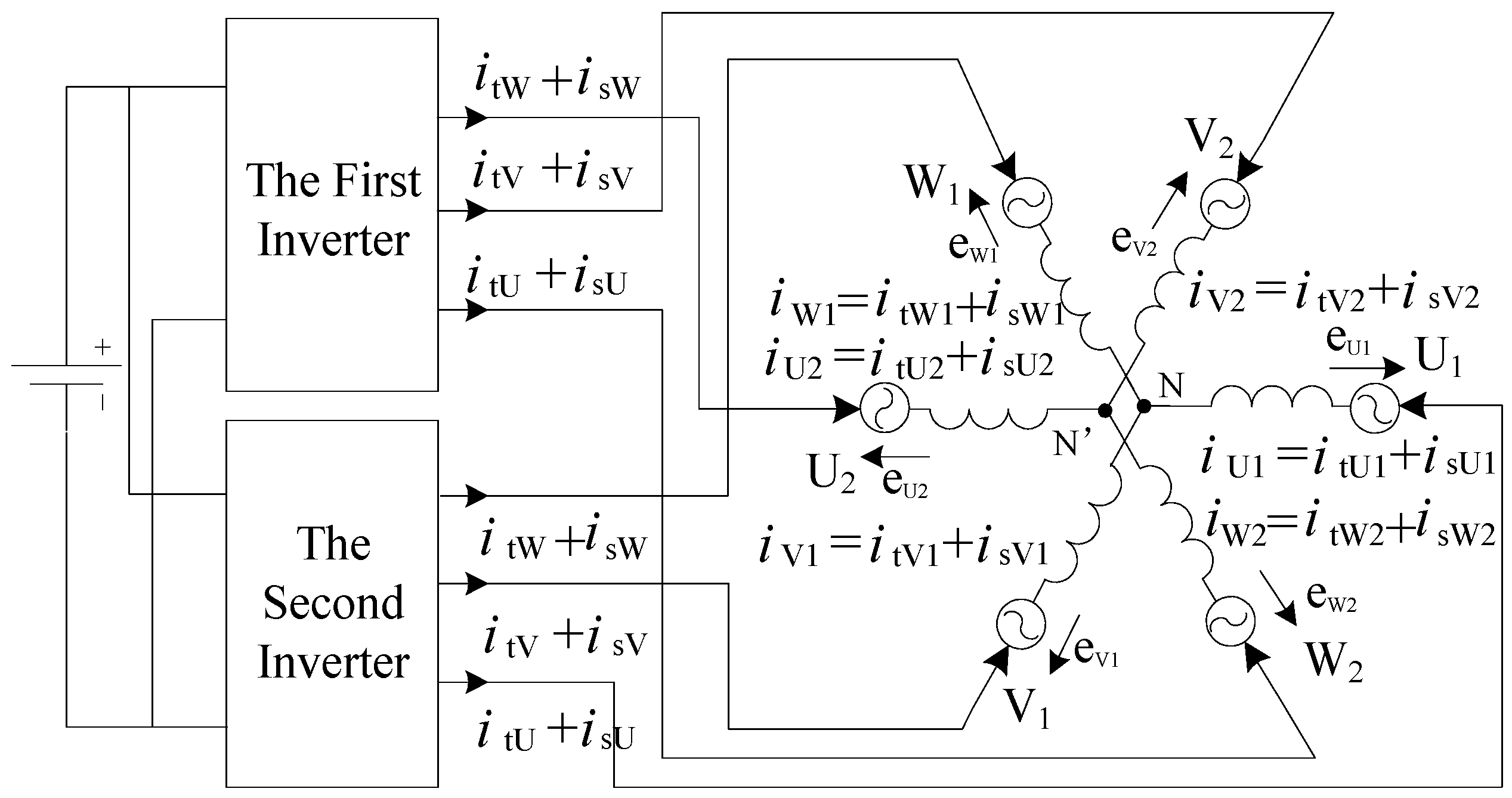
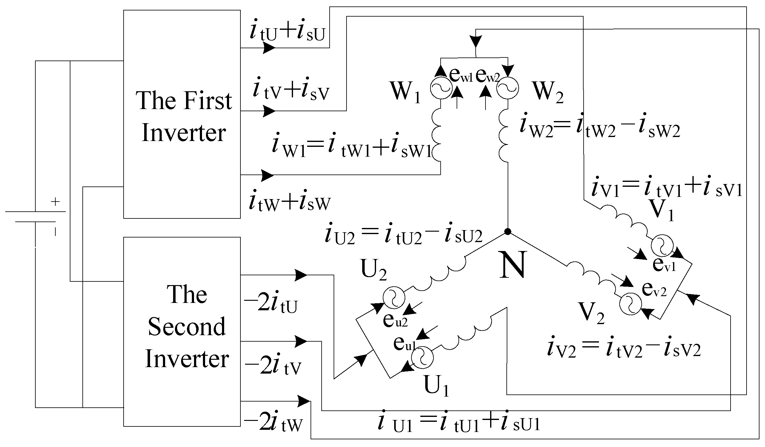
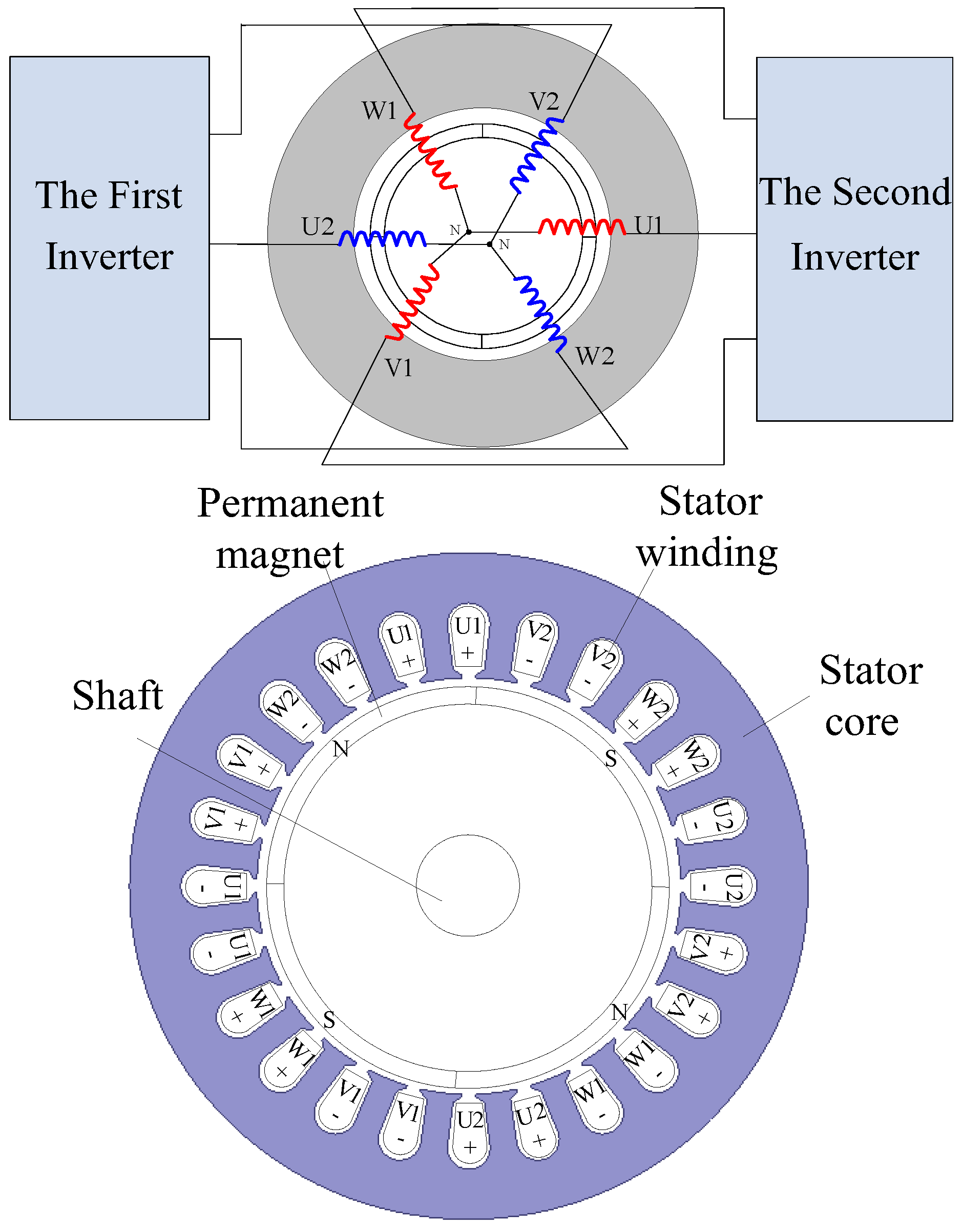
2. Improved Winding Structure and Operation Principle

Figure 1 shows the basic structure and winding configuration of a single winding double three-phase BPMSM, where there are two three-phase winding units, indicted by blue lines and red lines, respectively, supplied with two conventional three phase voltage source inverters. A 4-pole surface-mounted permanent-magnet with parallel magnetization is mounted on the rotor. The six phase windings of two three-phase winding units are wound around the 24-slots of an ordinary permanent magnet synchronous motor (PMSM). The phase difference of every three-phase winding unit in spatial distribution is 120 degrees, but the phase difference between two three-phase winding units is 180 degrees so it has a mirror image distribution is its description in stator mechanical space. Namely, U1 phase and U2 phase, V1 phase and V2 phase, W1 phase and W2 phase are symmetrical and defined as the corresponding phases. It is assumed that the beginnings of each winding unit are connected to the two inverters separately and the terminals of each three-phase winding units are connected as the two neutral points N separately. Therefore, the structure of this motor can be regarded as a dual Y shift 180 degrees double three-phase PMSM.
Therefore, when the torque current which drives the motor needs to be injected into the motor winding by the two inverters, the currents of each phase which belong to the same three-phase winding unit must be of equal amplitude and the phase-shift between them should be 120° and of positive order, but the corresponding phases are the same in the two winding units so that a two pole-pair revolving magnetic field can be generated in the air gap. When the suspension force current which suspends the rotor needs to be injected, the current phase difference of each three-phase winding unit likewise is 120 degrees, but the phases of the corresponding phases are the opposite in the two winding units so that a one pole-pair revolving magnetic field occurs in the air gap. To ensure the direction consistency of the two revolving magnetic fields, every phase current needs to be written as follows:
i tU 1 = I t cos ( ω t ) i tV 1 = I t cos ( ω t 2 π / 3 ) i tW 1 = I t cos ( ω t + 2 π / 3 ) i tU 2 = I t cos ( ω t ) i tV 2 = I t cos ( ω t 2 π / 3 ) i tW 2 = I t cos ( ω t + 2 π / 3 )
where it(U1~W2) refers to each phase torque current, is(U1~W2) specifies each phase suspension force current, It and Is is the magnitude of torque current and suspension force current, ω is the electric angular frequency of current.
From the electromechanics principle, the motor’s motional-EMF is generated in all windings at high rotational speed. The higher the speed, the larger a motional-EMF is generated. The suspension current will be greatly influenced, especially in cases of very small suspension current during typical operation time of motor, then the suspension force response will be delayed.
To overcome the interference of the high speed motor’s motional-EMF on the suspension force, the winding configuration should be modified. From the following analysis, the terminals in the corresponding phases of two three-phase winding units are connected, respectively, and the joints are extracted as the middle lines and form a T-shaped configuration, making the line interface of the whole motor reach a total number of nine. Three of the beginnings which belong to one of the three-phase winding units are linked to the first inverter, three of their middle lines are linked to the second inverter, and the remaining three beginnings of another three-phase winding unit are connected as the neutral point N. Therefore, when a sum of torque currents is injected into the motor winding by the first inverter, a double torque current with opposite direction is injected into the motor winding by the second inverter. Only symmetrical four-pole fluxes can be produced by the winding (in the motor), which makes the air-gap flux density equal on both sides of the air gap, so that only the torque is generated in the rotor. However the directions of the motor’s motional-EMF produced in the connected winding are reversed, and they are counteract so that no induced voltage appears at the first inverter output terminals. Meanwhile, when a series of suspension currents is injected into the motor winding by the first inverter, two-pole fluxes will occur in the air gap. Therefore, the unbalanced air-gap flux density results in a magnetic suspension force, and the response and amplitude of suspension current are no longer limited by the high motor motional-EMF. The currents of the two inverters should then be expressed as follows:
i stU 1 = I s cos ( ω t ) + I t cos ( ω t ) i stV 1 = I s cos ( ω t 2 π / 3 ) + I t cos ( ω t 2 π / 3 ) i stW 1 = I s cos ( ω t + 2 π / 3 ) + I t cos ( ω t + 2 π / 3 ) i tU 2 = 2 I t cos ( ω t π ) i tV 2 = 2 I t cos ( ω t π / 3 ) i tW 2 = 2 I t cos ( ω t + π / 3 )
where ist(U~W)1 is the winding current supplied by the first inverter, it(U~W)2 is the winding current supplied by the second inverter. Both the original and improved winding topologies of the motor structure are shown in Figure 2 and Figure 3. Because all three phase winding structures are symmetrical, thus, the U-phase winding is explained below.
The terminals in the U1 phase and U2 phase of two three-phase winding units are connected and the combination is extracted as the middle line and is linked to the second inverter. The beginning of the U1 phase is linked to the first inverter, then, the beginning of the U2 phase and the other two phases of the winding unit are connected as the neutral point N. In a similar manner, the connection mode is executed in the V-phase and W-phase.

3. The Analytical Expression of Suspension Force and Torque

3.1. Analytical Model of Suspension Force

As the magnetic field of the SBPMSM generated by the suspension current can be equivalent to the traditional BPMSM, the analytic suspension force model of a SBPMSM can be deduced by the Maxwell stress tensor method, like for a BPMSM. Based on the electromagnetic theory, Maxwell force and Lorentz suspension force both exist when the two sets of different sequences three-phase sinusoidal currents are injected to the motor winding, but considering the Lorentz force is relatively very small, it’s generally neglected. The Maxwell force consists of two main parts: eccentricity magnetic force and controllable radial force. The former refers to the uncontrollable radial force. When the rotor deviates from the center position, an asymmetric flux distribution is created causing an unbalanced magnetic pull so that the Maxwell force acting on the rotor and occurring as the negative stiffness coefficient force is not zero. The latter refers to the controllable suspension force. When the rotor is in its center position, if the suspension current is applied in the winding, the flux density is increased on one side of air gap, but decreased on the opposite side of the air gap, so the Maxwell force is likewise not zero and points in the magnetically enhanced direction.
As the number of pole pairs of two revolving magnetic fields Pt and Ps yields Ps = Pt – 1 (that is Ps = 1, Pt = 2), while considering the eccentricity of rotor, the suspension force components Fα, Fβ in the α-axis and β-axis can be written as:
{ F α = π l r B tf B s 2 μ 0 cos ( μ λ ) + π l r B tf 2 2 μ 0 δ 0 α F β = π l r B tf B s 2 μ 0 sin ( μ λ ) + π l r B tf 2 2 μ 0 δ 0 β
where μ0 is the vacuum permeability, l is the active length of the motor stator, r represents the stator inner diameter, Btf is the fundamental amplitude of the magnetic density synthesized by torque current and equivalent current of permanent magnet, Bs is the fundamental flux density generated by the suspension force current, μ and λ are the initial space angles of two fundamental magnetic densities, respectively. Using the vector current to replace flux density, Equation (3) can be also expressed as:
F α = k m i tf i s cos ( μ λ ) + k ecc α F β = k m i tf i s sin ( μ λ ) + k ecc β k m = 9 l r μ 0 N 2 k e 2 4 π δ 0 2 k ecc = 9 μ 0 l r N 2 k e 2 i f 2 8 π δ 0 3
where itf = it + if is the torque resultant current magnitude, it and if are the magnitudes of the torque current and the equivalent current of permanent magnets, respectively, is represents the suspension force current value, N is the number of turns of the winding, ke is the fundamental winding factor. As shown in Equation (4), the Maxwell force is proportional to the amplitudes of the suspension current while the torque current remains invariable and the rotor is in the central position, and its direction is up to the phase-difference of the initial space angle μ and λ. For more details on the mathematical formula of the suspension force, readers may refer to [18].

3.2. Analytical Model of Torque

According to the winding structure shown in Figure 2 and Figure 3, the vector of the phase voltage u, phase current i and phase flux linkage ψ can be written as:
i = [ i U 1 i U 2 i V 1 i V 2 i W 1 i W 2 ] T u = [ u U 1 u U 2 u V 1 u V 2 u W 1 u W 2 ] T ψ = [ ψ U 1 ψ U 2 ψ V 1 ψ V 2 ψ W 1 ψ W 2 ] T
Then, the current dynamics are determined by the stator voltage equation:
u = R i + L p i + ω d ψ d t
where R refers to matrix of the resistance of the motor winding, L specifies the matrix of the inductance of the motor winding, p is a differential operator. Due to the symmetry of the stator winding and the rather big air gap between the stator and rotor, which involves equal self-inductances and coupling inductances (these inductance parameters are solved by the energy perturbation method [19]), this avoids solving the flux linkage associated with each winding directly. Meanwhile, the flux linkages generated from the permanent magnet in the symmetric winding are the same, namely, ψU1 = ψU2, ψV1 = ψV2, ψW1 = ψW2:
L 1 = L U 1 = L V 1 = L W 1 = L U 2 = L V 2 = L W 2 L 2 = L U 1 W 2 = L W 2 V 1 = L V 1 U 2 = L U 2 W 1 = L W 1 V 2 = L V 2 U 1 L 3 = L U 1 V 1 = L W 2 U 2 = L V 1 W 1 = L U 2 V 2 = L W 1 U 1 = L V 2 W 2 L 4 = L U 1 U 2 = L W 1 W 2 = L V 1 V 2
where L1 is self-inductance, L2, L3 and L4 are coupling inductances between phases. By taking U1 phase and U2 phase as an example, the voltage equation can be also expressed as:
u U 1 = R i U 1 + L 1 p i U 1 + L 2 p ( i V 2 + i W 2 )   + L 3 p ( i V 1 + i W 1 ) + L 4 p i U 2 + ω d ψ U 1 d t u U 2 = R i U 2 + L 1 p i U 2 + L 2 p ( i V 1 + i W 1 )   + L 3 p ( i V 2 + i W 2 ) + L 4 p i U 1 + ω d ψ U 2 d t
If the flow direction of the suspension current is taken as the positive direction, the synthesis current should be written as:
i U 1 = i tU + i sU i U 2 = i tU + i sU i V 1 = i tV + i sV i U 2 = i tV + i sV i W 1 = i tW + i sW i U 2 = i tW + i sW
where it(U–W) is the torque current, and is(U–W) is the suspension force current.
It can be seen from Equations (8) and (9), that when the double windings topology of the motor structure is applied, because there is no torque current in the suspension force winding, the inverter that only gives suspension current is not affected by the torque current. When the original winding topology of the motor structure which is shown in Figure 2 is applied, the terminal voltage of each inverter will be influenced by both the torque current and the suspension force current, especially the motor’s motional-EMF. When the improved T-shaped winding topologies of the motor structure which is shown in Figure 3 is applied, the voltage u U 1 + U 2 of the first inverter output terminals is given as:
u U 1 + U 2 = u U 1 + u U 2 = 2 R i sU 1 + 2 ( L 1 L 4 ) p i sU 1 + 2 ( L 2 L 3 ) p ( i sV 1 + i sW 1 )
The bearingless motor is fed by a pulse width modulation (PWM) voltage-source inverter. From Equation (10), it can be seen that the terminal voltage of the first inverter is determined only by the suspension current rather than the torque current, because the torque current is eliminated, and it also means motor’s motional-EMF is eliminated. Then, the current commands of the first inverter are generated by detecting the torque current and suspension current.
[ i stU i stV i stW ] = [ i sU i sV i sW ] + [ i tU i tV i tW ]
And the current commands of the second inverter are generated just by detecting the torque current:
[ i tU i tV i tW ] = 2 [ i tU i tV i tW ]
The Finite Element Method is an effective means to analyze the operating principle and performance of the motor. In this paper, the finite element models are established and the motor’s motional-EMF analysis carried out by means of the Maxwell Ansoft 16 Finite Element analysis software.
When the rotation speed is 3000 r/min, the waveforms of the no-load motional-EMF and finite element models of three different winding structures and connections are shown in Figure 4. The three structures in Figure 4 are to show, from left to right, the double windings, original T-shaped single winding and improved T-shaped single winding structures. As can be seen from Figure 4a, due to the two sets of windings configuration, the suspension force current control needs to be taken irrespective of the influence of the motor’s motional-EMF generated in the torque winding. The no-load motional-EMF values of the torque winding are indicated by the solid lines, and the amplitude is about 120 V, but the motional-EMF values represented by dashed lines in the suspension winding is low and the amplitude is only 13.6% of that of the torque winding. As shown in Figure 4b, due to the fact two sets of currents need to be injected into same winding by the two inverters, the no-load motional-EMF will vary with different speeds, so the motional-EMF amplitude is also about 120 V in all windings at 3000 r/min so that it should be considered when the terminal voltage of the first inverter is determined. It is found that no induced voltage appears at the first inverter output terminals, due to the T-shaped winding configuration applied from Figure 4c. The solid lines and dashed lines represent the no-load motional-EMF values generated by the torque current and suspension current, respectively. These amplitudes are about 210 V and 30 V, respectively and the amplitude of the no-load motional-EMF of the generated suspension current is only 14.3% of that generated by the torque current. Because the suspension current is provided only by the first inverter, its response cannot be limited by the motor’s motional-EMF and the finite element analysis results are thus in agreement with the analysis presented in Section 3.2.
Furthermore, the FEA results of the torque and suspension force have been made at 3000 r/min based on the improved T-shaped single winding configuration, when a torque current of 8 A and suspension force current of 3 A are fed into the single winding and the results are shown in Figure 5.
The dashed line represents the electromagnetic torque; its average value is about 8.5 N·m and pulsation of torque is about 1 N·m. The solid line indicates the radial suspension force; its amplitude is maintained at between 130–140 N. The performance of the torque and radial suspension force can be improved by the optimization of the permanent magnet thickness, pole-arc coefficients and air-gap length, etc. [20].

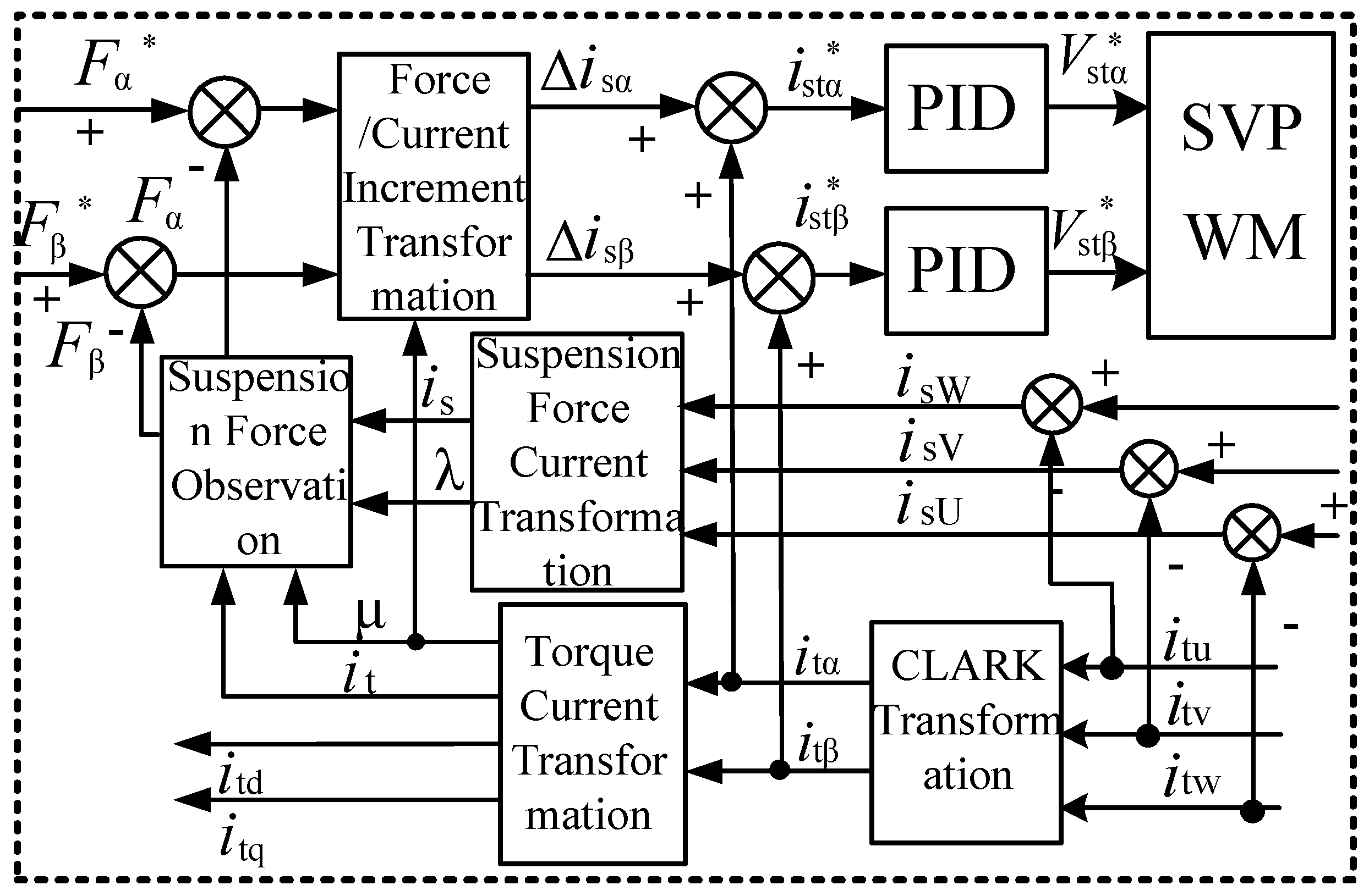
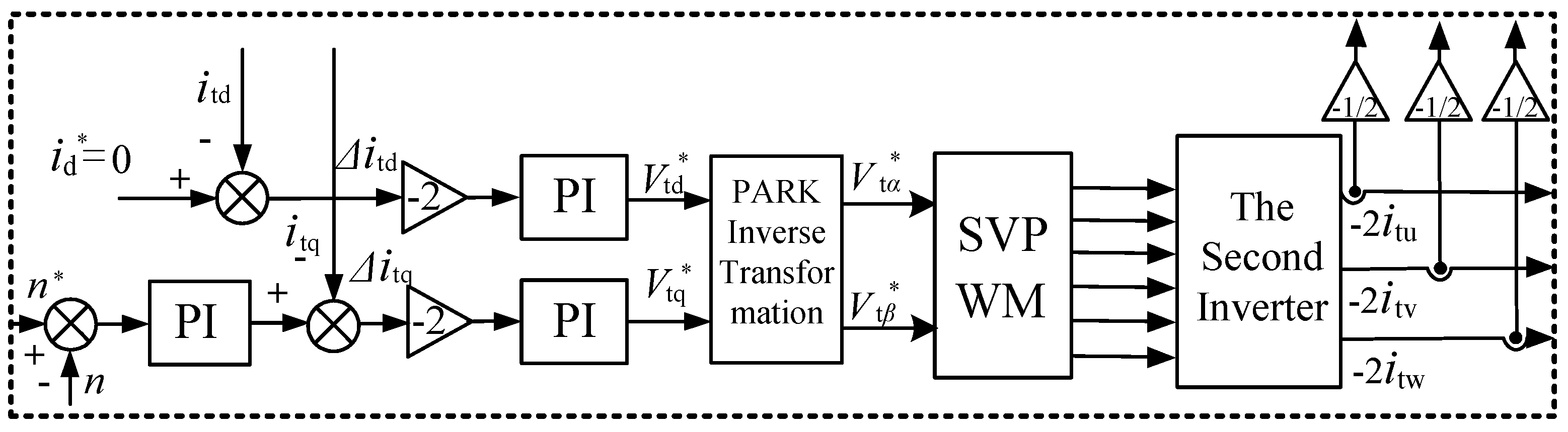
4. Closed Loop Control of Suspension Force Vector of SBPMSM

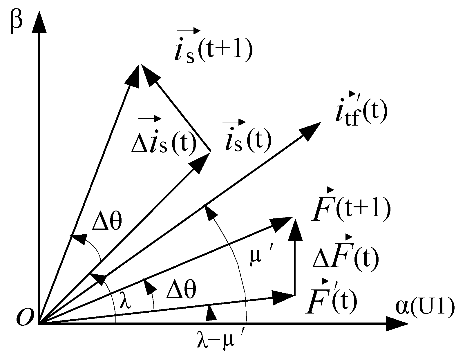
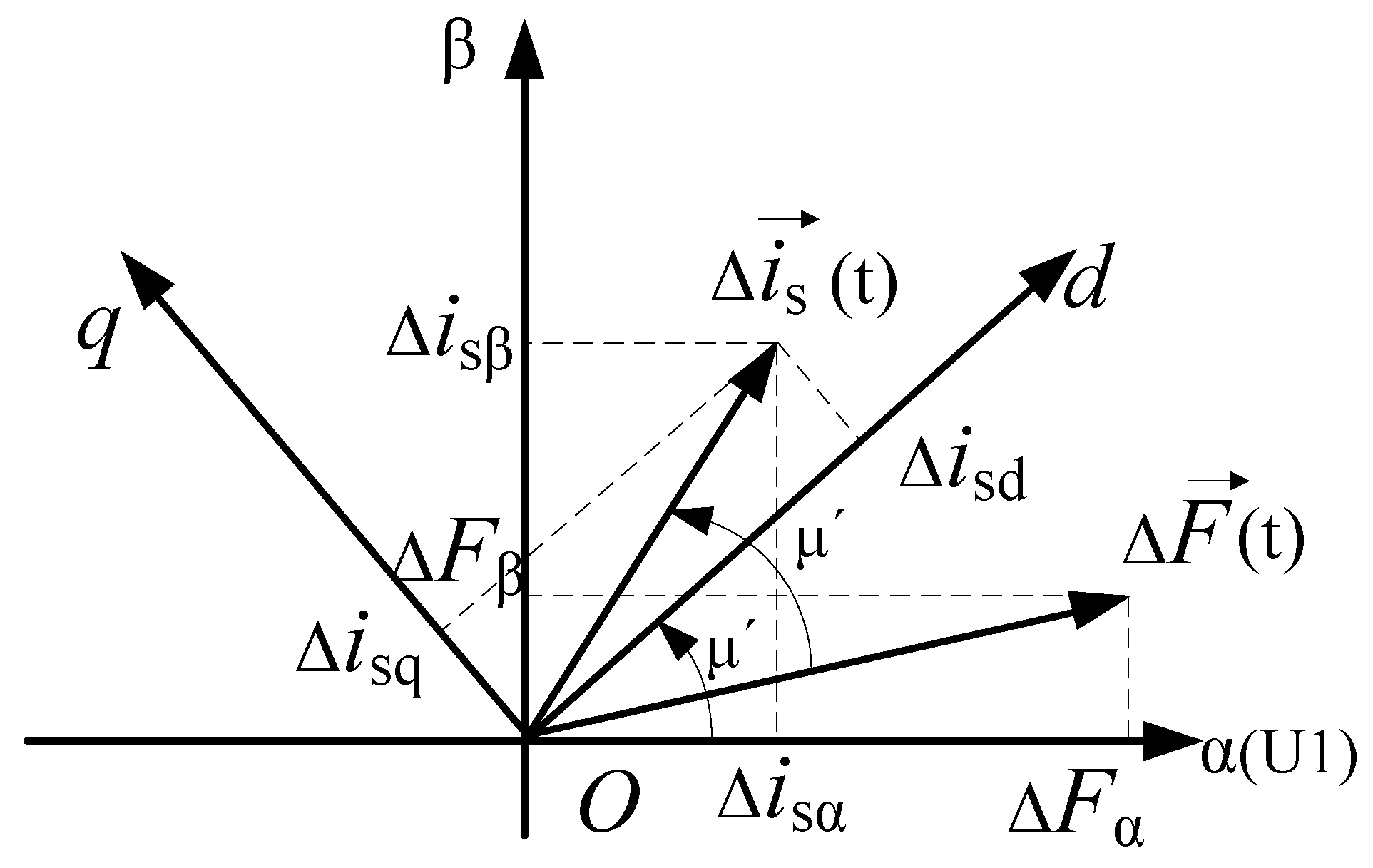
4.1. Principle of Closed Loop Control of Suspension Force Vector

The traditional suspension force control system is a single closed-loop control system, which is adjusted only by the negative displacement feedback, so the accuracy and celerity of displacement tracking is largely limited. Based on the principle of direct suspension force control (DSFC) in [15], which core is Equation (13), an inner radial suspension force closed-loop (computed in real time by on-line identification of current) is added to the single closed-loop control system, which core is Equation (14) and which details are described in Section 3.1. The actual radial suspension force can be computed by the observation of the amplitude and phase of the suspension force current and the torque current. The suspension force vector estimation in this paper can not only enhance the accuracy and dynamic response performance of the control system, but also reduce the computational complexity, making it more fit for real-time processing:
{ F α = k M ψ tf ψ s cos ( λ μ ) F β = k M ψ tf ψ s sin ( λ μ )
{ F α = k m i tf i s cos ( λ μ ) F β = k m i tf i s sin ( λ μ )
Figure 6 shows the suspension force vector and current vector diagram. λ is the angle between suspension force current vector is and U1-phase winding axis, µ is the angle between the torque current resultant equivalent current of the permanent magnet vector itf and the U1-phase winding axis, λ − µ is the angle between radial suspension force vector F and the U1-phase winding axis. As seen from the Figure 6, the value of the suspension force depends upon both the amplitudes and phases of the two sets of currents. The possible torque variation in the startup and steady-state stage of motor is first considered for generating a stable radial suspension force. Therefore, the amplitude and phase of synthesis equivalent current itf should be accurately determined first. The magnitude and phase of the actual radial suspension force are adjusted only by means of controlling the value of the suspension force current.
To ensure the consistency and versatility of the above control strategy under any set of circumstances, especially in transient state operation, the relationship between the two sets of current components and suspension force need to be analyzed under the condition of accurate calculation of the values of the two sets of current components. The small-signal model is applied for an explicit and detailed analysis, like the direct suspension force control (DSFC) analysis method. Supposing that the increase of electromagnetic torque is ΔTe during the period from t to moment t + 1, this causes torque current resultant equivalent current of permanent magnet vector itf will be changed, while its amplitude will be reduced to be itf (t) and its phase will be increased to be μ′. Then, the changed torque produces suspension force vector changes from F(t) to F′(t), the phase value becomes λ μ′ (as shown in Figure 7), derived from Equation (15). It can be written as:
{ F α ( t ) = k m i tf ( t ) i s ( t ) cos ( λ μ ) F β ( t ) = k m i tf ( t ) i s ( t ) sin ( λ μ )
There is a proportional relationship between the variation of suspension force and the variation of suspension force current. The difference between them is 1/Kmitf(t) times according to geometry knowledge shown in Figure 7. The angle should be computed as λ − (λ − μ′) = μ′ which is the same as the angle between vector itf(t) and vector F′(t). Assuming suspension force command is F(t + 1) at moment t + 1, as follows:
{ F α ( t + 1 ) = k m i tf ( t ) i s ( t + 1 ) cos ( λ + Δ θ μ ) F β ( t + 1 ) = k m i tf ( t ) i s ( t + 1 ) sin ( λ + Δ θ μ )
Figure 8 shows the transformation of the suspension force current components and suspension force. In the stationary coordinates, it can be obtained as:
( Δ F α Δ F β ) = k F ( cos μ sin μ sin μ cos μ ) ( Δ i sd Δ i sq )

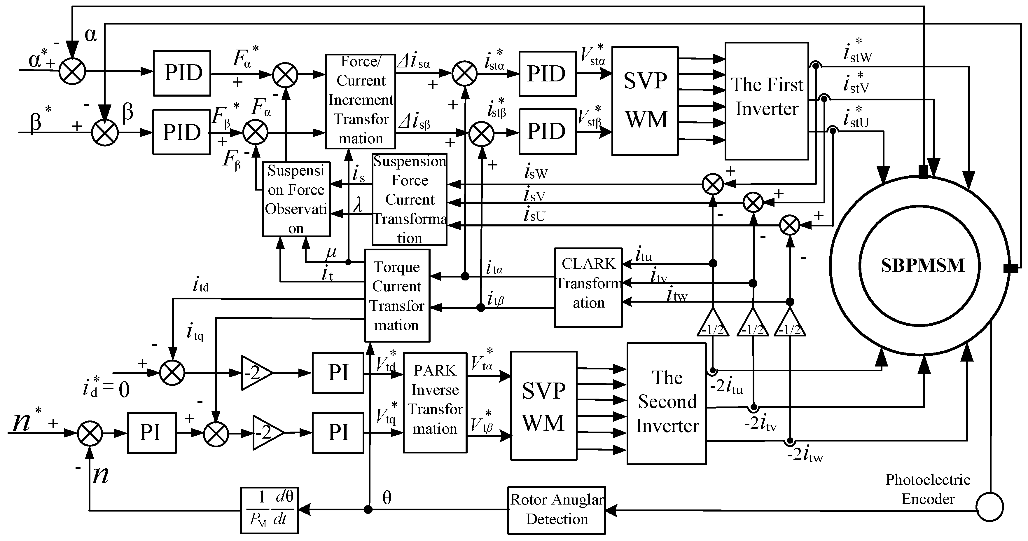
4.2. Regulation System

The detailed block diagram of the suspension force vector control based on the analytical model and principle noted above in Section 3.1 and Section 4.1 is shown in Figure 9. The torque current components i and i in the two phase stator coordinate system (α- and β-axis) are transformed into d- and q-axis currents itd and itq by the detected angular position θ and fed back to the torque control system. Its amplitude it and phase μ are computed as the current feedback signals. Then, the suspension current feedback signals are detected by Hall current sensors, its amplitude is and phase λ are computed by means of the three phase suspension force current ia, ib and ic which had been subtracted from a half of the torque current. The suspension force components Fα and Fβ are thus calculated by Equation (13). Compared with the suspension force commands Fα* and Fβ*, the errors between them can be transformed into the current increment Δisα and Δisβ by the Force/Current Increment Transformation module. The suspension force current commands istα* and istβ* must be added to the torque current feedback values i and i, then, the reference voltage vectors Vstα* and Vstβ* are gained and used for one SVPWM Control Module by Proportional-Integral-Derivative (PID) Controllers.
The detailed block diagram adopting the torque control strategy is shown in Figure 10 based on the proposed above-motor T-shaped winding configuration and the analytical model in Section 2 and Section 3.1. The torque current commands itq* produced by the speed error and a Proportional-Integral (PI) controller. Due to the adoption of field orientation control, the torque current command itd* is defined as zero. Then, the torque current commands of the PI controller input must be carried out the double and opposite torque current increment Δitd and Δitq in the rotary coordinate system, the reference voltage vectors Vtd* and Vtq* are gained from the PARK inverse transformation by the PI controllers and their signals are sent to another SVPWM Control Module. Therefore, the three phase torque current feedback values needed are valid when the torque current detected by the Hall current sensors must decrease by half.
For the details of the relevant control system-like the field orientation control in torque control part and radial displacement closed-loop control part readers can refer to [12]. The controller schematic program of double closed loop vector control (DCLVC) for the SBPMSM is shown in Figure 11.

5. Simulation and Experiment

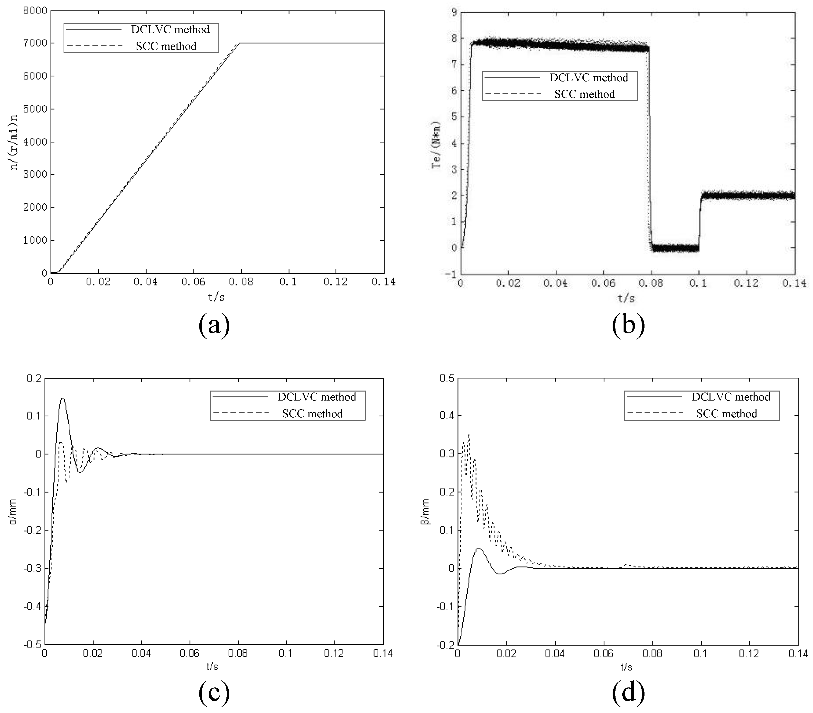
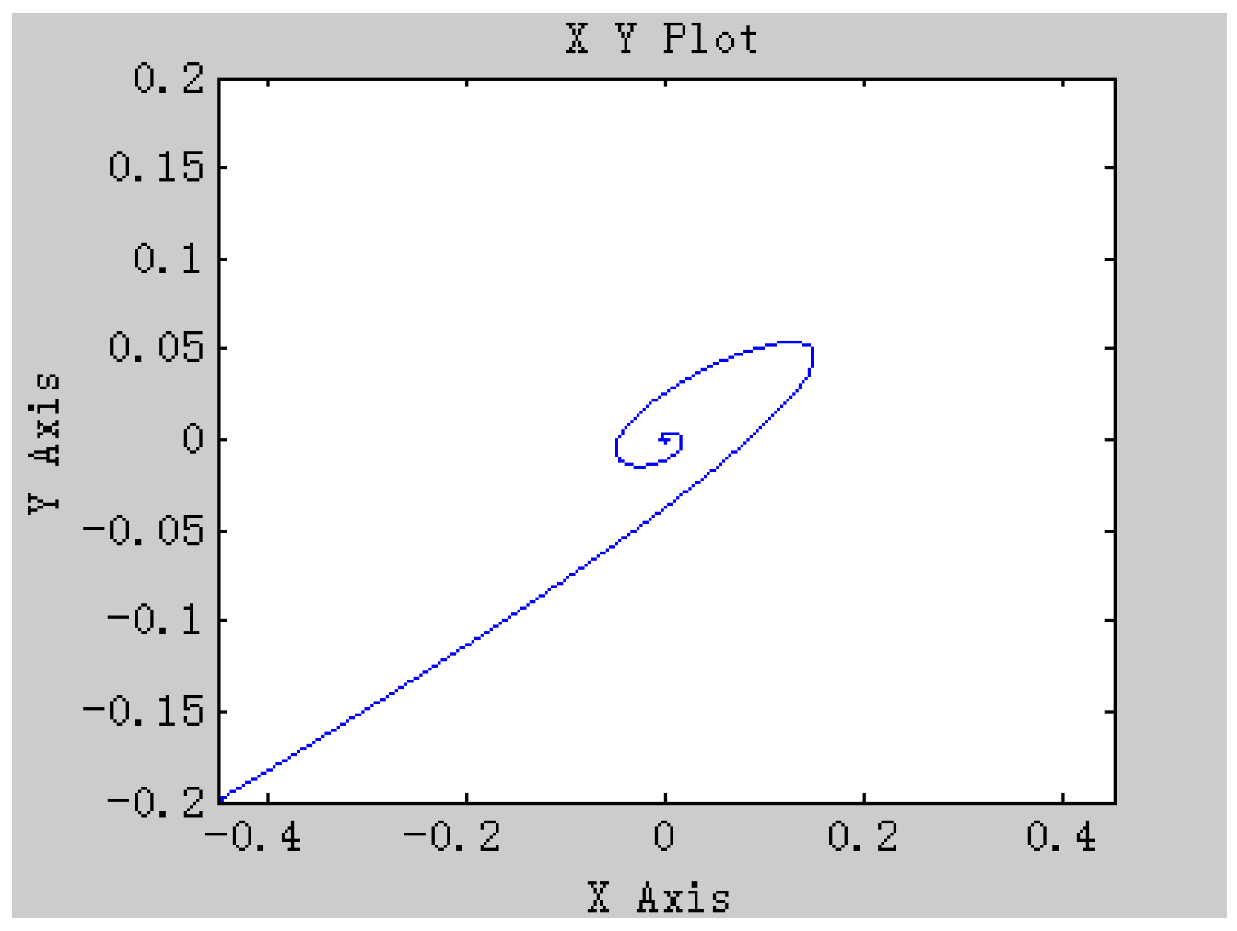
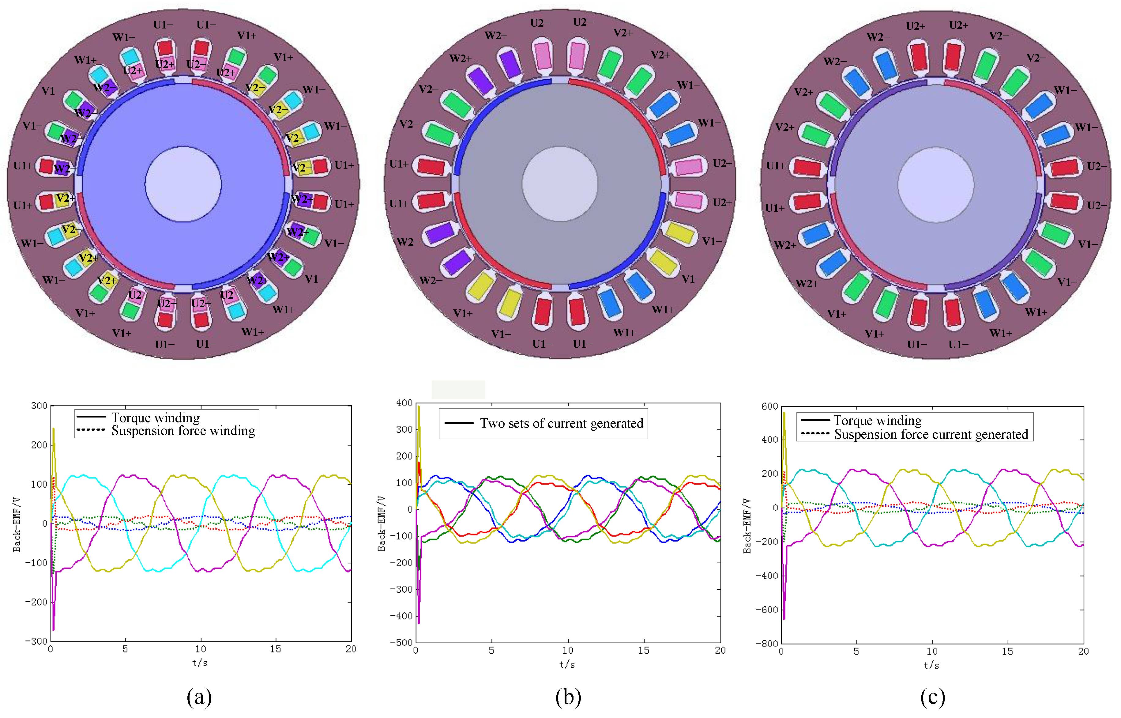
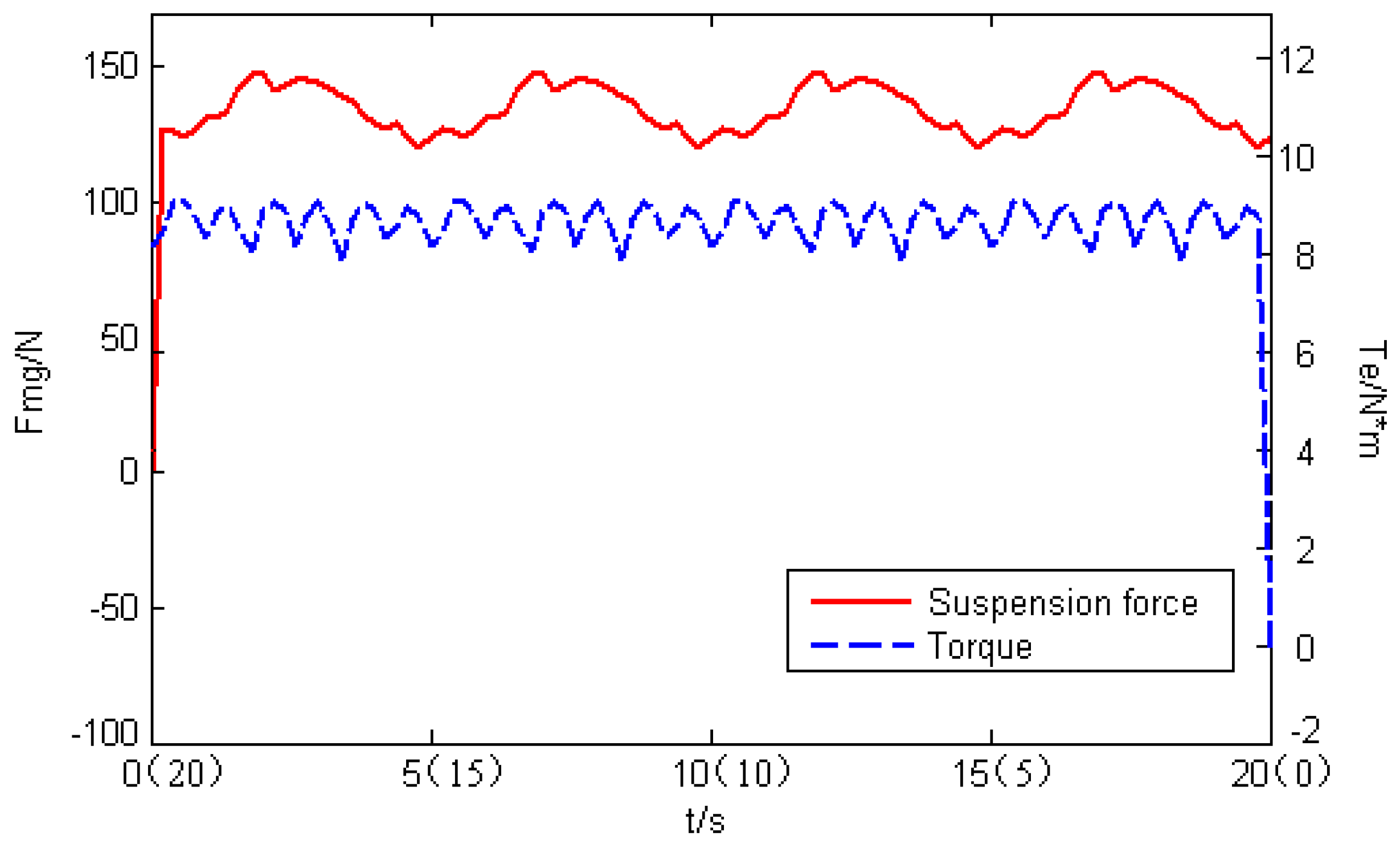
5.1. Analysis of Simulation Results

To verify the feasibility of the control strategy, the MATLAB/Simulink environment has been used for the simulation. The simulation parameters are listed in Table 1. Moreover, Figure 12 shows the simulation results of both the DCLVC strategy introduced in Section 4 and the suitable current control (SCC) method proposed by [21]. The solid lines indicate the former control strategy results and the dashed lines indicate the latter control method results. Figure 12a illustrates the motor speed response curves from launch to rated speed under the two different control system conditions, respectively. The dynamic response time is the same where both responses take 0.08 s. Figure 12b illustrates the electromagnetic torque response curves, where the starting torque is about 8 N·m, and it jumped to 0 N·m as the speed stabilizes at 0.08 s because no load is imposed on the system.
After 0.1 s, a 2 N·m disturbance is imposed. As can be seen, the dynamic response curves are almost the same under the two different control system conditions. This shows that the DCLVC system corresponding the T-shaped winding configuration did not have any effect on the motor torque control strategy part. In the radial α- and β- positioning diagrams presented in Figure 12c,d, the rotor can be back to the equilibrium position from the original eccentric position (α = −0.45 mm, β = −0.2 mm) after an short time of unstable oscillation under the two different control system conditions, but there is some distinction in the adjustment process. Figure 13 shows the track for the mass center of the rotor under the DCLVC system. The rotor approaches to the center in a helix track, and suspends stably in the center.

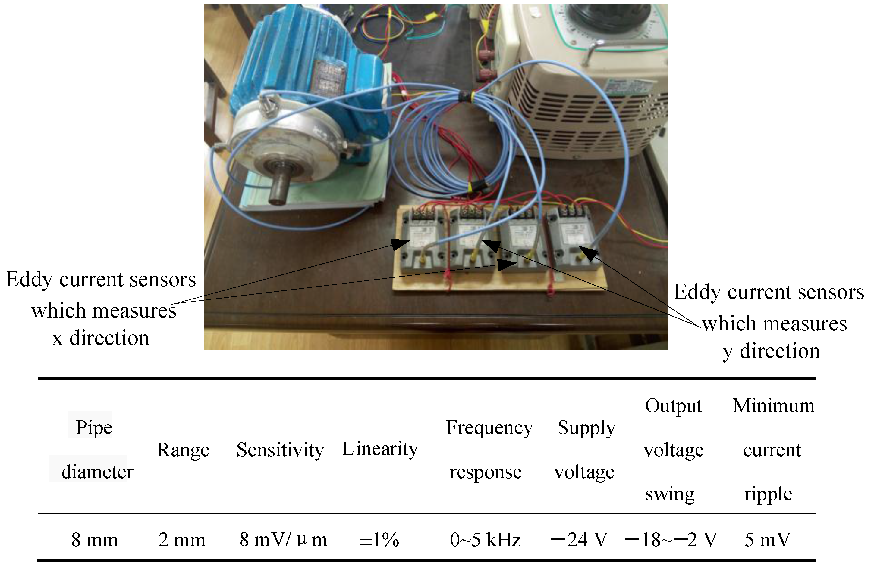
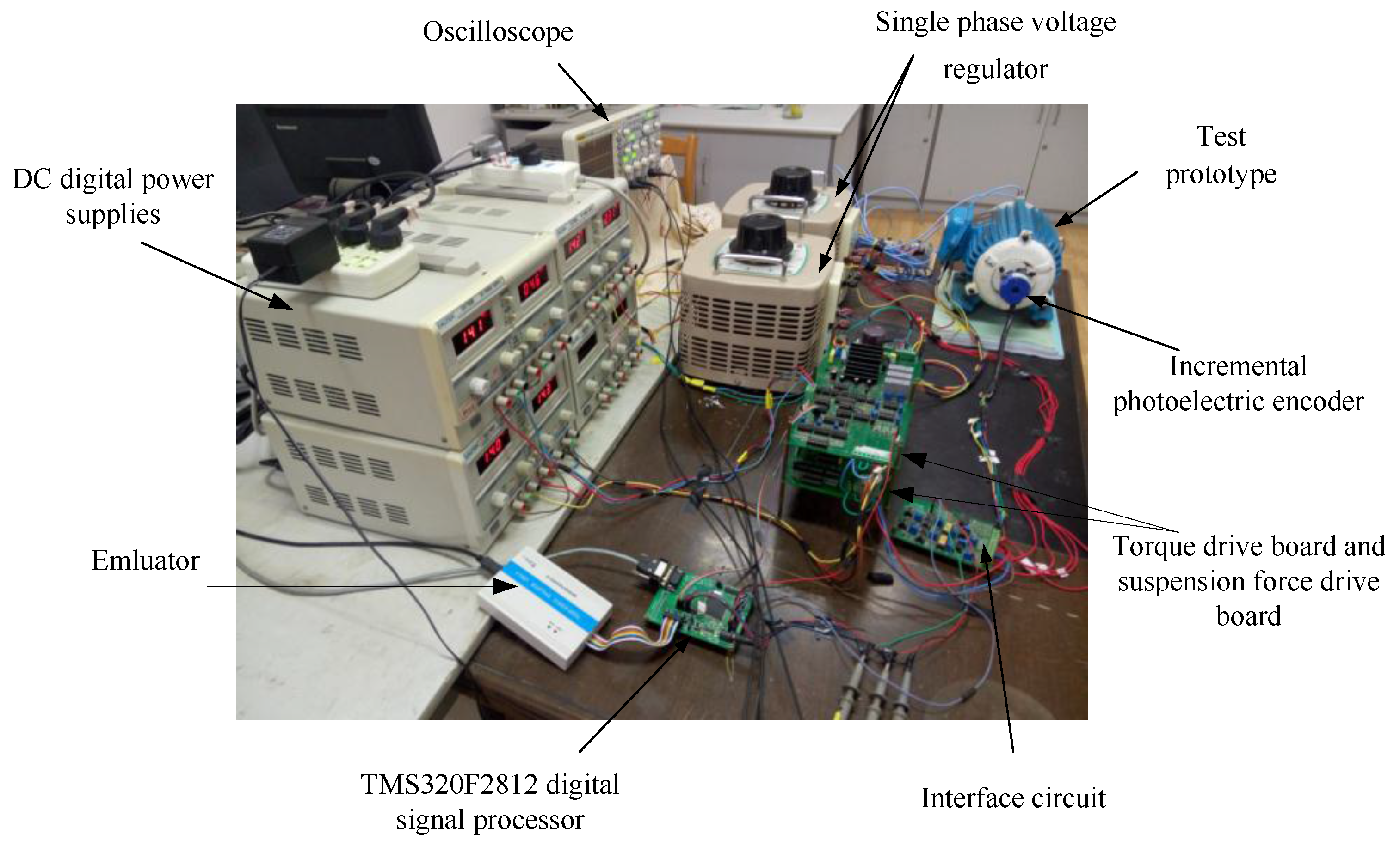
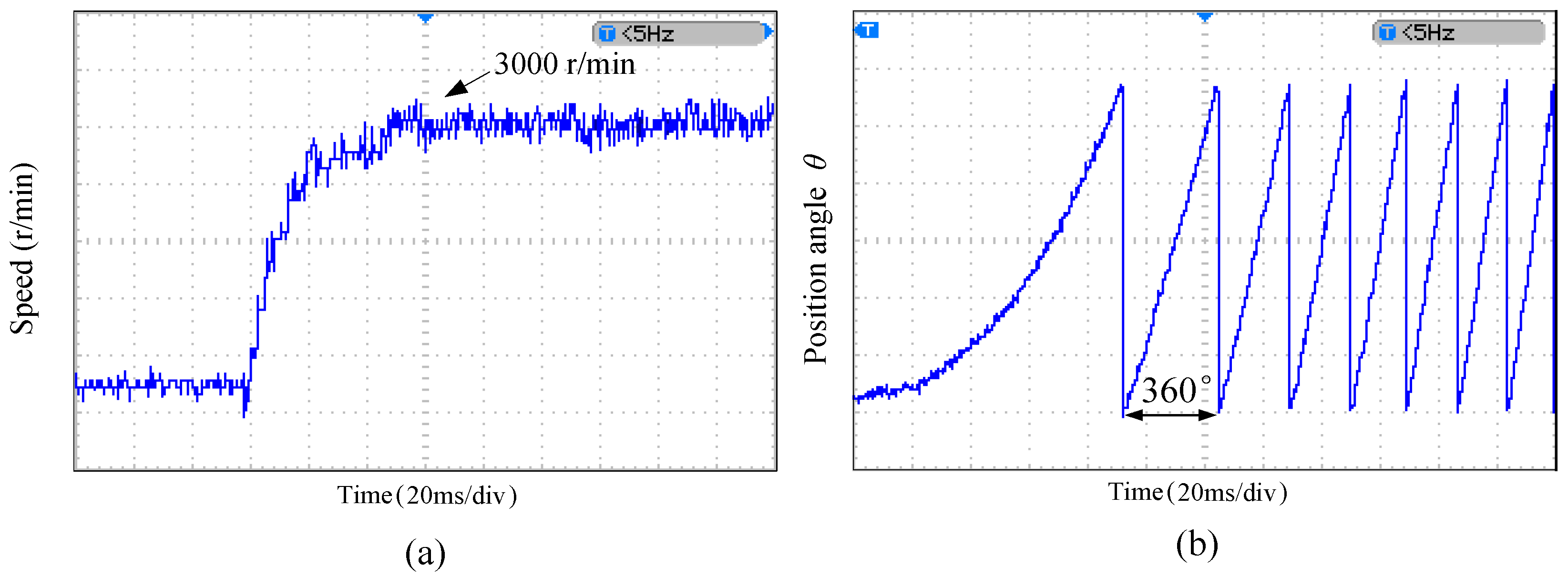
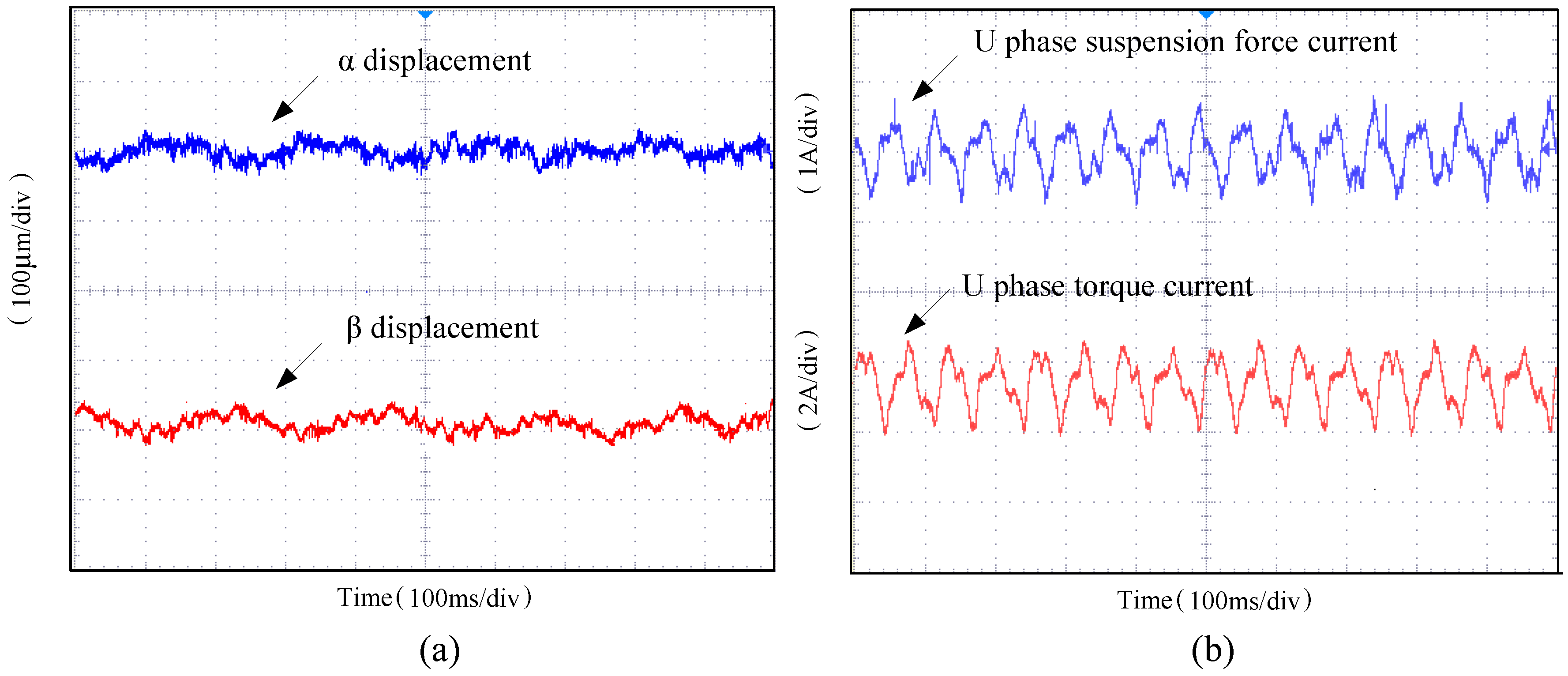
5.2. Analysis of Experimental Results

In order to further verify the effectiveness and correctness of the T-shaped single winding configuration and the suspension force vector closed loop control strategy mentioned in the section above and the simulation results, the experiment is carried out on a traditional surface mounted BPMSM, which motor interior windings have been rearranged based on the T-shaped winding wiring mode. The prototyping ontology is as follows: winding turns N is 30; air gap length g is 1 mm; permanent magnet thickness d is 3 mm; the air gap length of the auxiliary bearing is 0.5 mm. The hardware control platform is a TMS320F2812 digital signal processor plus a hardware interface circuit and a power driver circuit board. Figure 14 shows the experimental platform using the digital control system.
Figure 15 show the measured waveforms of rotational speed and the waveform of the rotor position angle, respectively. The acceleration test results for the proposed the suspension force vector closed loop control strategy are shown in Figure 15a. The rotational speed is stepped up from launch to 3000 r/min. In Figure 15b, the rotor position angle changes periodically with time in the range of 0°~360° from launch to rated speed. The corresponding frequency is 50 Hz which is in agreement with the calculation formula for rotational speed when the rotation speed of the motor is 3000 r/min. Thereby, the reasonable operating characteristics of the speed closed loop is verified at 3000 r/min. It showed that the system did not produce any effects on motor torque performance, and simulation results are validated by experiments.
In order for the rotor to realize suspension and run steadily, the rotor displacement must be accurately measured in real time. The characteristic of the eddy current sensor that the output voltage value is linear with eccentric displacement can address this issue. Four QH8500 eddy current sensors are applied to estimate the rotor radical displacement in this experiment, whose real model and parameters are shown in Figure 16.
Figure 17a shows the radial displacement waveforms in the α- and β-direction. It shows that the suspension force current obtained by the suspension force vector closed loop control method can create enough radial suspension force to restrict radial reciprocating motion of the rotor at the center of the air-gap. The final stable displacement in the positive α-direction is less than ±0.023 mm, and the final stable displacement in the positive β-direction is less than ±0.020 mm. Figure 17b shows the current waveforms of the suspension force and torque of the U phase winding. Hence it can be established that closed loop control of the suspension force vector can achieve the desired effect, maintaining the stability of the rotor.

6. Conclusions

In this paper, firstly, to overcome the interference of the high motor motional-EMF on the suspension force, an improved T-shaped winding structure is introduced based of the winding structure of a single winding double three-phase BPMSM, and simulation waveforms of no-load motional-EMF, torque and suspension force are compared and analyzed at 3000 r/min by means of FEA software.
Secondly, the analytical models of the suspension force and torque are derived. Lastly, a new closed loop control method of the suspension force vector for the SBPMSM is applied to overcome the shortcomings of poor control accuracy in the traditional suspension force control system, and constitute a DCLVC system. The control method is simulated by the MATLAB software and verified in an experimental prototype. Conclusions can be drawn as follows: the improved T-shaped winding structure is reasonable and effective, the new control strategy can achieve the desired effect, improving the control accuracy of radial suspension force.

Acknowledgments

This work was sponsored by National Natural Science Foundation of China (60974053), Jiangsu Province University Achievements in Scientific Research Industrial Production Advancement Project (JHB2012-39), Jiangsu Province “Qinglan Project” (2014), and Jiangsu Province “333 Project” (2014).

Author Contributions

Huangqiu Zhu proposed the control method and performed simulation analysis, Jianfei Yuan carried out the modification of the winding configuration and drafted the manuscript, Jintao Jv assisted in control software compilation test. All authors discussed the results and approved the final manuscript.

Conflicts of Interest

The authors declare no conflict of interest.

References

  1. Sun, X.; Chen, L.; Yang, Z. Overview of bearingless permanent-magnet synchronous motor. IEEE Trans. Ind. Electron. 2013, 60, 5528–5538. [Google Scholar] [CrossRef]
  2. Li, H.; Zhu, H.Q. Bearingless motor’s radial suspension force control based on virtual winding current analysis. In Proceedings of the 17th International Conference on electrical Machines and Systems, Hangzhou, China, 22–25 October 2014; pp. 2141–2146.
  3. Eric, S.; Robert, N.; Ned, M. Dual-purpose no-voltage winding design for the bearingless AC homopolar and consequent pole motors. IEEE Trans. Ind. Appl. 2015, 51, 2884–2895. [Google Scholar]
  4. Reichert, T.; Nussbaumer, T.; Johann, W. Bearingless 300W PMSM for bioreactor mixing. IEEE Trans. Ind. Electron. 2012, 59, 1376–1388. [Google Scholar] [CrossRef]
  5. Asama, J.; Hamasaki, Y.; Oiwa, T. Proposal and analysis of a novel single-drive bearingless motor. IEEE Trans. Ind. Electron. 2013, 60, 129–138. [Google Scholar] [CrossRef]
  6. Nenninger, K.; Amrhein, W.; Silber, S. Bearingless single-phase motor with fractional pitch winding. In Proceedings of the 7th International Symposium on Magnetic Bearings, With Exhibition, Zurich, Switzerland, 23–25 August 2000; pp. 371–376.
  7. Chiba, A.; Sotome, K.; Iiyama, Y. A novel middle point current injection type bearingless PM synchronous motor for vibration suppression. IEEE Trans. Ind. Appl. 2011, 47, 1700–1706. [Google Scholar] [CrossRef]
  8. Kang, M.; Huang, J.; Jiang, H.B.; Yanget, J.Q. Principle and simulation of a 5-phase bearingless permanent magnet-type synchronous motor. In Proceedings of the International Conference on Electrical Machines and Systems, Wuhan, China, 17–20 October 2008; pp. 1148–4452.
  9. Zhu, J.; Deng, Z.Q.; Wang, X.L.; Liao, Q.X. Principle and implementation of the single winding bearingless permanent magnetic slice motor. Proc. CSEE 2008, 28, 68–74. [Google Scholar]
  10. Khoo, W.K.S. Bridge configured winding for poly phase self-bearing machines. IEEE Trans. Magn. 2005, 41, 1289–1295. [Google Scholar] [CrossRef]
  11. Chiba, A.; Horima, S.; Sugimoto, H. A principle and test results of a novel bearingless motor with motor parallel winding structure. In Proceedings of the IEEE Energy Conversion Congress and Exposition, Denver, CO, USA, 15–19 September 2013; pp. 2474–2479.
  12. Eric, S.; Srikant, G.; Ned, M. Practical implementation of dual purpose no voltage drives for bearingless motors. In Proceedings of the IEEE Applied Power Electronics Conference and Exposition (APEC), Charlotte, NC, USA, 15–19 March 2015; pp. 819–826.
  13. Zhu, H.Q.; Wang, C.B.; Tan, E.; Li, T. Mathematical model and control technology of bearingless PMSM. In Proceedings of the IEEE Control and Decision Conference (CCDC), Xuzhou, China, 26–28 May 2010; pp. 3175–3179.
  14. Zhang, S.R.; Luo, F.L. Direct control of radial displacement for bearingless permanent magnet type synchronous motors. IEEE Trans. Ind. Electron. 2009, 56, 542–552. [Google Scholar] [CrossRef]
  15. Chou, Z.J.; Deng, Z.Q.; Wang, X.L. A study on independent control of the bearingless permanent magnet synchronous motor. Proc. CSEE 2006, 26, 115–119. [Google Scholar]
  16. Zhu, H.Q.; Tan, E. Direct torque and direct suspension force control of bearingless permanent magnet synchronous motor based on SVM. In Proceedings of the IEEE Control and Decision Conference (CCDC), Xuzhou, China, 26–28 May 2010; pp. 2411–2415.
  17. Silber, S.; Amrhein, W. Power optimal current control scheme for bearingless PM motors. In Proceedings of the 7th International Symposium on Magnetic Bearings, with Exhibition, Zurich, Switzerland, 23–25 August 2000; pp. 401–406.
  18. Sun, X.D.; Chen, L.; Yang, Z.B.; Shi, K. Modeling of a bearingless permanent magnet synchronous motor considering rotor eccentricity and coupling relationship of winding. Trans. China Electrotech. Soc. 2013, 28, 63–70. [Google Scholar]
  19. Wang, Q.J.; Ma, F.; Li, G.L.; Chen, J. The analysis and calculations on 3-dimensional field and inductance of a claw-pole alternator under no-load condition. Proc. CSEE 2002, 22, 38–42. [Google Scholar]
  20. Li, B.N.; Huang, J. Design and function analysis of multiphase PM bearingless motor with single set of winding. Large Electr. Mach. Hydraul. Turbine 2012, 10, 1–4. [Google Scholar]
  21. Ribeiro, R.L.A.; Castro, F.E.F.; Salazar, A.O.; Maitelli, A.L. A suitable current control strategy for split-phase bearingless three-phase induction machine. In Proceedings of the Power Electronics Specialists Conference (PESC), Recife, Brazil, 16 June 2005; pp. 701–706.
Figure 1. Schematic of a single winding bearingless permanent magnet synchronous motor.
Energies 09 00377 g001
Figure 2. Winding topology of single winding double three-phase BPMSM.
Energies 09 00377 g002
Figure 3. Winding topology of improved SBPMSM.
Energies 09 00377 g003
Figure 4. The no-load motional-EMF of a BPMSM with different winding structures. (a) The two sets of windings configuration; (b) The single winding configuration; (c) The improved T-shaped single winding configuration.
Energies 09 00377 g004
Figure 5. Torque and suspension force of improved T-shaped SBPMSM.
Energies 09 00377 g005
Figure 6. Diagram of the suspension force vector and current vector.
Energies 09 00377 g006
Figure 7. The relationship between the increment of suspension force and the suspension force current.
Energies 09 00377 g007
Figure 8. Transformation of the suspension current components and suspension force.
Energies 09 00377 g008
Figure 9. Block diagram of the suspension force vector control.
Energies 09 00377 g009
Figure 10. Block diagram adopting the torque control strategy.
Energies 09 00377 g010
Figure 11. DCLVC block diagram of SBPMSM.
Energies 09 00377 g011
Figure 12. Simulation results of the control system of SBPMSM. (a) Comparison of speed characteristics; (b) Comparison of torque characteristics; (c) Comparison of the α-axis displacements; (d) Comparison of the β-axis displacements.
Energies 09 00377 g012
Figure 13. Rotor trajectory.
Energies 09 00377 g013
Figure 14. SBPMSM experimental platform using digital control system.
Energies 09 00377 g014
Figure 15. The experimental results of the control system. (a) The measured waveforms of rotational speed; (b) The waveform of the rotor position angle of SBPMSM stable operation to 3000 r/min.
Energies 09 00377 g015
Figure 16. The real models and parameters of the QH8500 eddy current sensors.
Energies 09 00377 g016
Figure 17. The experimental results of the control system. (a) The radical displacement of the α- and β-directions of stable operation; (b) The U phase currents of suspension force and torque when the motor rotation speed is 3000 r/min.
Energies 09 00377 g017
Table 1. Parameters of SBPMSM.
ParameterSymbolValue
Rated mechanical powerPN500 W
Stator slot countQ24
Mechanical air gap lengthδ01 mm
Magnet thicknessd3 mm
Pole pair countPB2
Winding resistanceRa2.43 Ω
Winding inductanceLa1.25 mH
Moment of inertiaJ0.82 g·m2
Initial position of rotorα−0.45 mm
Initial position of rotorβ−0.2 mm
Rotor massm2.625 kg

