1. Introduction
The conventional means of electric energy production have been recently considered to be replaced by renewable resources due to the increasing concerns of environmental degradation, depletion of fossil fuels, increasing fossil fuel prices,
etc. [
1,
2,
3]. Accordingly increasing renewable energy penetration and also new types of loads, such as electric vehicles, have necessitated the adoption of smart solutions by the electricity industry [
4,
5,
6,
7].
In order to enable the local utilization of the energy produced and to defer the need of new investments in power delivery systems, distributed generation (DG) units are considered a promising solution within the smart grid vision. However, the presence of DG, especially in distribution systems, is likely to be associated with some drawbacks, as well [
8,
9,
10,
11,
12,
13]. The integration of DG units increases the complexity in the operation, control and protection of medium and low voltage power systems [
14,
15]. The impacts of DG on the protection of distribution systems have been analyzed in many research studies [
16,
17,
18,
19,
20,
21,
22]. The following two aspects must be considered during the protection scheme analysis in the presence of DG.
The power flow in the distribution system is unidirectional when DG is not connected. However, the power flow becomes bi-directional in many sections of the distribution system, and as a result, conventional protection schemes considering just one-way power flow become insufficient.
The DG units contribute significantly to short circuit currents. Besides, connection/disconnection events of DG units may have a short-term impact on the current magnitudes, especially when dealing with large wind turbines that are typically equipped with asynchronous generators that draw high currents during their connection to the system.
Another issue related to renewable sources-based DG is their dependence on meteorological conditions, such as wind speed, solar radiation, etc. This leads to frequent connection/disconnection of the DG units to the system, e.g., because of variable wind speed and the intermittent nature of photovoltaic (PV) generation.
Thus, conventional protection schemes that are designed for power systems without considerations of the DG impacts are insufficient for supporting wider renewable energy-based DG penetration [
23,
24,
25,
26,
27,
28]. Thus, a new generation of protection schemes that explicitly considers these requirements and adapts the system operation are strongly required [
29,
30,
31,
32]. Furthermore, two types of operating modes, namely the grid-connected and islanded modes, may occur, and the relevant necessities for protection should be re-evaluated [
33].
In the literature, several studies [
9,
19,
34,
35,
36,
37,
38] showed that the sensitivity and the operating time of the over-current relays (OCRs) are affected by the presence of DG. The coordination between OCRs is closely related to the network topology changes, as proven in [
39]. The islanded mode of operation was discussed in [
40,
41] in terms of the effective operation of OCRs.
Clearly, new solutions regarding the adaptation of relay parameters to changes in network topology have been considered as a necessity in the recent literature. In this regard, the studies in [
41,
42,
43,
44,
45,
46,
47] suggested the adaptive protection scheme considering several types of relays (distance relays, OCRs,
etc.), also considering grid-connected and islanded mode of operations. However, none of the aforementioned studies considered the adaptive protection scheme together with different operating modes with the presence of DG. Besides, to the best knowledge of the authors, all of the relevant studies in the literature handled the adaptive protection issue from a static point of view. Here the term “static” refers to the fact that the mentioned studies provided the setting values of the protection devices neglecting the possible dynamic operational mode changes within the system structure due to the connection/disconnection events especially of renewable-based DG units. This is a vital issue that needs to be further evaluated as the connection of a large-scale DG unit can contribute to the short-term current magnitude and short circuit levels in the system, and if the system does not “dynamically” adapt itself to this new configuration, it is very likely to face disoperation of protection devices (e.g., unnecessary or delayed tripping).
Thus, in this study, a dynamic strategy for adaptive protection and relay coordination is proposed, and protection recommendations related to the analysis of various fault scenarios during the grid-connected/islanded mode for DG-based distribution systems are given. The contribution of the study is four-fold:
It jointly considers the impacts of availability scenarios for multiple DG units with protection schemes in a dynamic structure, while previous studies consider static structures without investigating DG operating modes related to their availability.
It considers both grid-connected and islanded modes of operation.
The proposed method implements relay coordination in different operating modes and enables fast fault isolation compared to conventional protection schemes considering different grid scenarios and fault conditions.
It presents a modular structure allowing the consideration of DG presence at all system buses.
The rest of this paper is organized as follows. The methodology and the test system are described in
Section 2. The obtained results are presented and discussed in
Section 3. Finally, concluding remarks are presented in
Section 4.
2. System Description and Methodology
The proposed algorithm is tested on the IEEE 13-node system, and case studies considering DG units connected at several locations of the grid structure are evaluated for different fault locations.
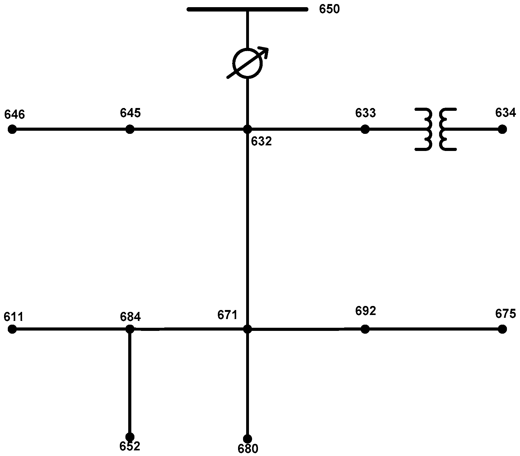
The original IEEE 13-node test system is shown in
Figure 1. The source is a 115-kV line-to-line infinite bus. The relevant data for the test system are presented in
Table 1 and
Table 2 [
48]. However, the original version of this test system is not sufficient to demonstrate the proposed methodology for the following reasons:
There is only one source, and no DG units exist in the original structure.
The power flow is unidirectional.
The original system is unsuitable for islanding conditions.
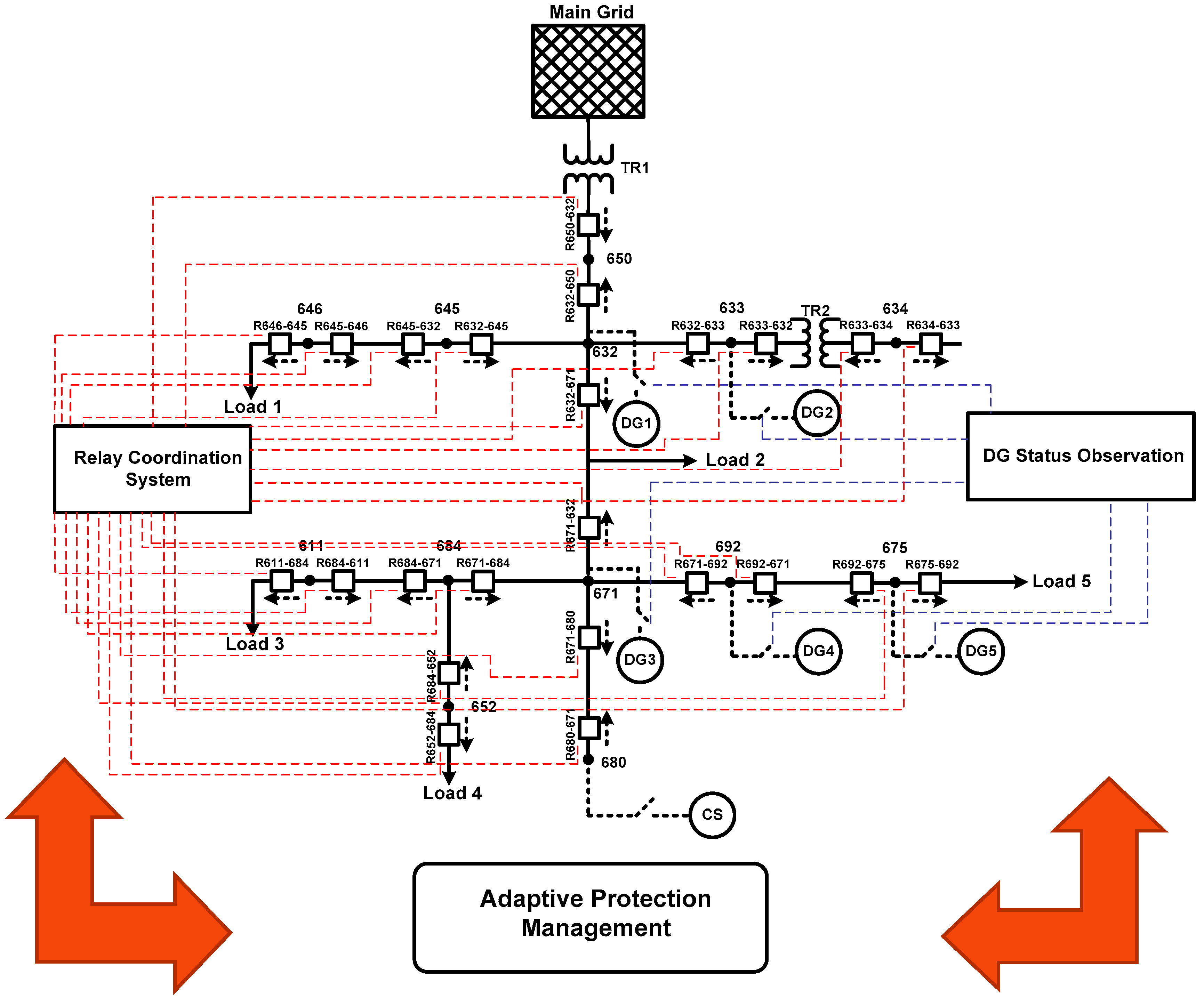
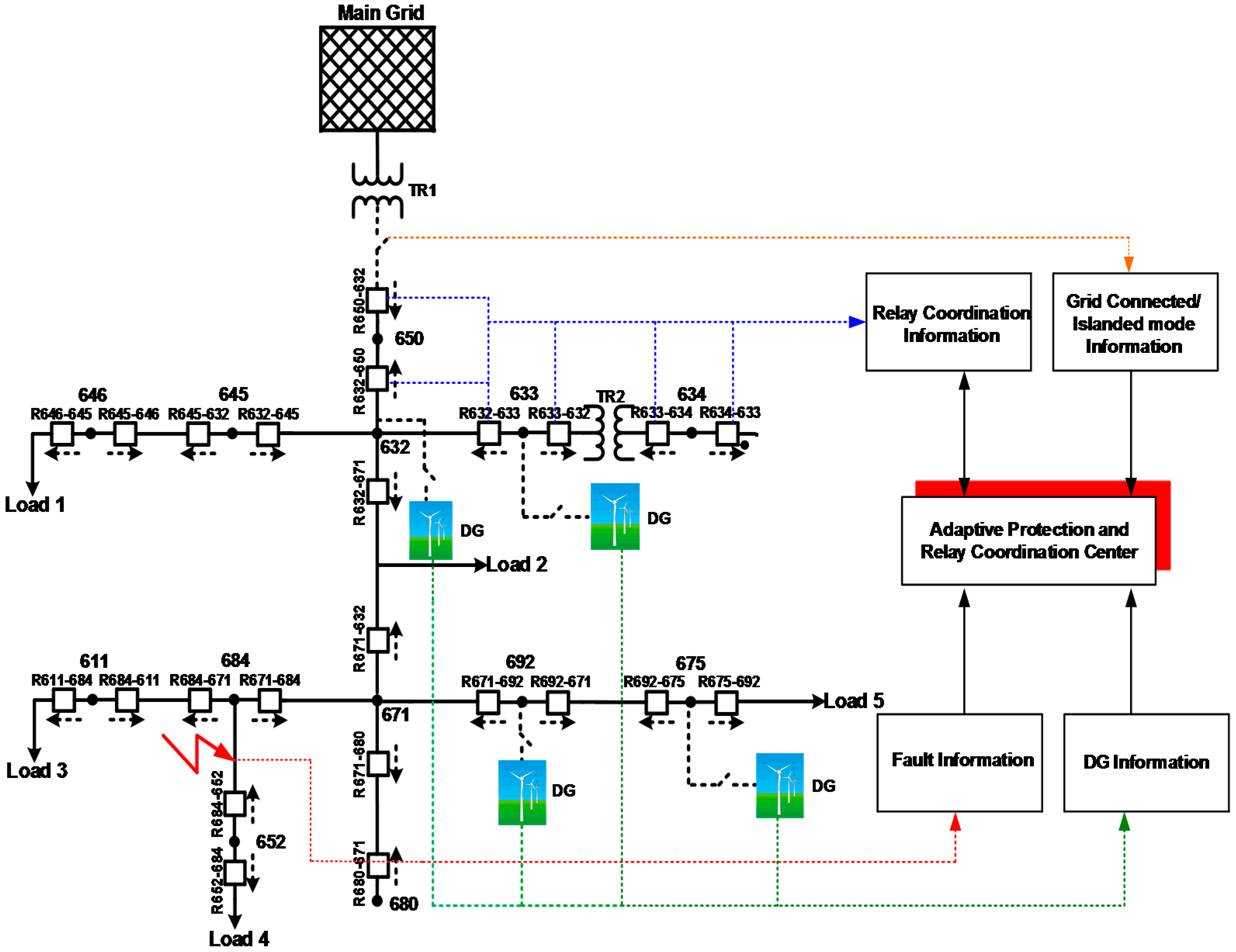
In order to test the performance of the proposed strategy, the system is modified as follows (
Figure 2):
DG units are connected to Buses 632, 633, 671, 675 and 692.
Since the modified system is subjected to bi-directional power flows, new relays for the opposite direction are added near the main relays.
A conventional source (CS) is connected at Bus 680 for the islanding mode study.
It should be noted that the additional DG units are considered to be, without loss of generality, wind energy conversion systems with the same power rating, as can be seen in
Figure 2. Furthermore, as the modified test system is subjected to bi-directional power flow, directional over-current protection is used against the fault current that could circulate in both directions through the system. When the DG unit(s) are connected to the grid, there are multiple local power sources. Hence, the nature of the distribution system changes with multiple DG units. Consequently, directional over-current relays (DOCRs) along the line are required in the system, and they should be placed along the line that links the main grid with the DG [
49].
The tripping of relays is provided using a time delay where the relay located at the furthest point from the source is tripped in the shortest time. The consecutive relays to the direction of the source are then tripped with greater time delays regarding the general selectivity concept. The characteristic curves for the relay operations are defined in the IEC 60255 [
50] as follows:
where
t is the operating time of relay, Time Multiplier Setting (TMS) is the relevant set point for relay coordination,
Is is the pickup current of the relay and
If is the fault current. It should be noted that the pickup currents are normally set above the maximum load current.
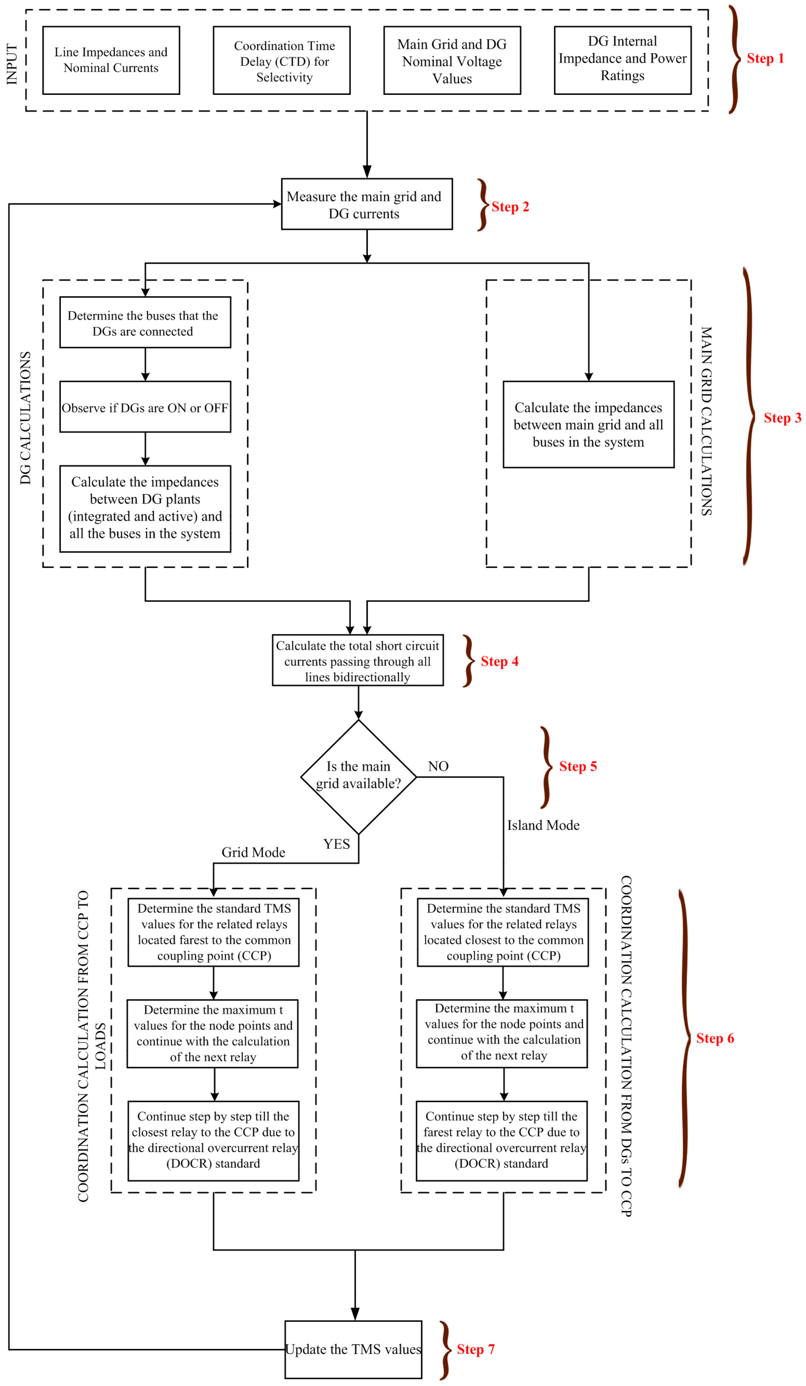
The flowchart of the algorithm to ensure the adaptive relay coordination in the modified IEEE 13-node system is depicted in
Figure 3. The algorithm is explained step-by-step as follows:
- Step 1
The inputs required by the algorithm are introduced.
- Step 2
The measurement of the currents of the main grid and DG plants is realized. These measurements are then used for the calculations performed in Step 3 for the main grid and DG plants.
- Step 3
This step consists of two separate parts. In the first part, the general calculations related to the DG are performed. These calculations start with the determination of buses where DGs are connected. Then, the observation of the active or passive state of each DG plant is identified by observing if the mentioned DG injects current to the system or not. If yes, the DG is considered to be active in the relevant time period; else, the contrary holds. Lastly, calculations of impedances between active DG plants and each bus in the system are performed. For the main grid calculations, the impedances between each bus of the system are calculated.
- Step 4
The calculations of total possible short circuit currents in both directions in each line are performed in this step.
- Step 5
The analysis of the fact of whether or not the main grid is available is realized in this step. If the main grid is available, then the adaptive relay coordination is realized for grid-connected mode. If not, the mentioned calculations are provided for islanded mode operation.
- Step 6
This step also consists of two steps depending on the operating status of the system that is identified in Step 5. If the system is in grid-connected mode, firstly, the standard TMS value is assigned for the relay that is connected to the most remote location with respect to the point of the common coupling of the DG. Then, the selectivity-based calculations for each of the consecutive relays are performed using Equation (1). For the nodal points, the tripping times of the relays on the lines connected to the node are compared, and the greatest tripping time among them is selected to continue for the consecutive relay till the closest relay to the point of common coupling. A similar calculation is realized for the islanded mode, but this time from the relay that is connected at the closest location with respect to the point of common coupling of the DG to the relay that is connected to the most remote location.
- Step 7
In this step, the TMS values are dynamically updated for the current time period, and then, the algorithm continues for the next time period.
3. Test and Results
This section presents the results of the case studies based on the performance evaluation of the proposed adaptive protection scheme. The simulations are performed using the MATLAB/Simulink/SimPowerSystems environment (MathWorks, Natick, MA, USA).
Several scenarios are examined in order to test the system performance considering both grid-connected and islanded modes of operation. In each scenario, different fault locations are selected and different DGs are considered to be available and active where relevance between the connection of such units to the distribution system and the protection strategy are observed. Here,
Table 3 and
Table 4 explain the grid mode descriptions.
The DG connection point in the following refers to the bus at which the DG plant is connected to the system. Different connection points are selected within the IEEE 13-node test system in each scenario considering the load dispersion and grid characteristics. The results are obtained for conditions where one or multiple DGs are active in the system.
The selectivity method is considered separately for grid-connected and islanded modes of operation. In order to test the success of the developed adaptive protection scheme in grid-connected mode, adaptive and conventional schemes are compared. In the conventional scheme, the selectivity calculations are realized considering that all DGs are available and are producing at a full loading condition. The major drawback of this method is that any change in the system operation (passive state of a connected DG, etc.) is not captured, and therefore, the selectivity calculations cannot be updated dynamically. This issue causes an insufficient protection scheme in new generation smart grid structures, and this leads to the necessity of an adaptive scheme for the successful protection and relay coordination in different dynamic operating conditions. Thus, all of the changes in system (operating mode, active DGs among connected DGs, changes in short circuit currents, etc.) are observed in order to dynamically update the TMS values of relays by the developed algorithm.
In the islanded mode, it is considered that the infinite grid is not available and that the power production is realized solely by the DGs. Here, conventional, semi-adaptive and adaptive schemes are compared. The conventional scheme for islanded mode is the same as the grid-connected mode, as in conventional schemes, the calculations are provided regardless of detecting any islanding situation in the system. In the semi-adaptive mode, the system can detect if the main grid is available or not and can update the relay settings for the islanding condition; however, the DG status changes are neglected in this update process. Lastly, the adaptive scheme considers both the availability of the main grid and the status of DGs. The relevant pickup current
Is values for the system are also given in
Table 5.
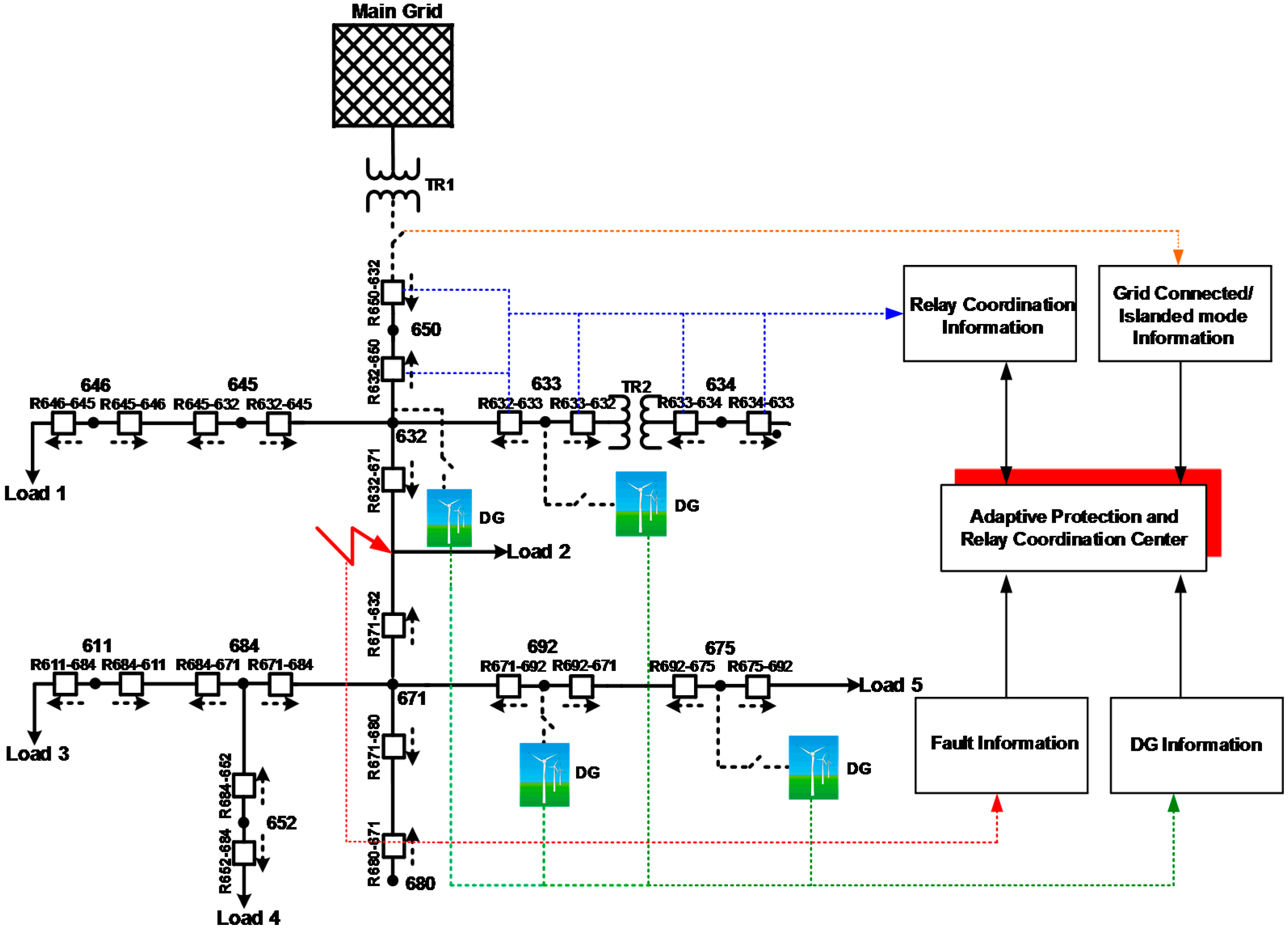
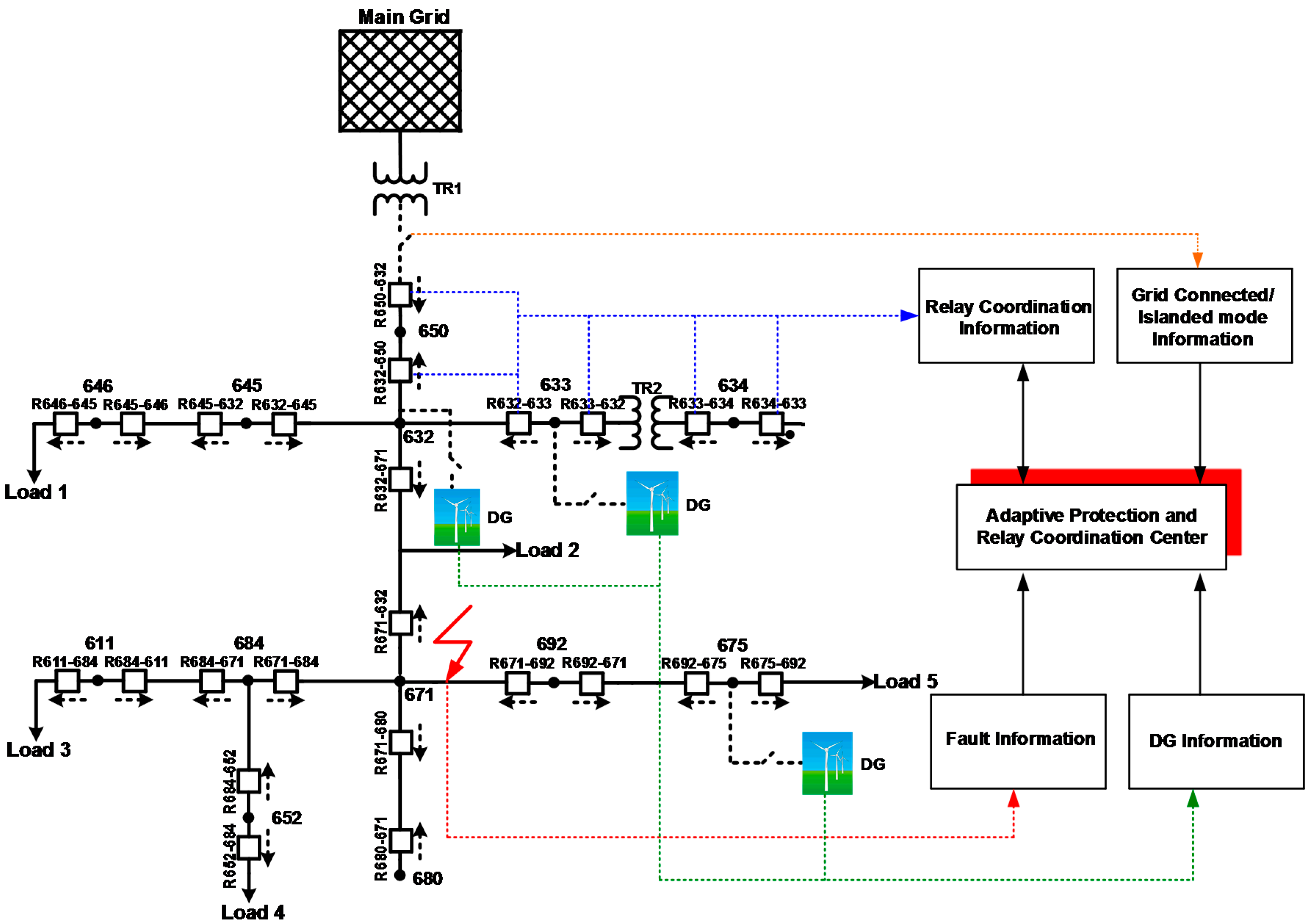
3.1. Scenario 1
The first scenario considers a modified version of the IEEE 13-node test system as seen in
Figure 4. Wind energy-based DGs are connected at Buses 632, 633 and 675 in the system. However, it should be noted that in different sub-cases that will be discussed in
Table 6 and in all upcoming result tables, the active DG can be only one DG or a group of DGs among the available DGs in the system. The fault location is selected as the line between 671 and 692 located near Bus 671. The adaptive protection and relay coordination center ensures an information flow (the set points of all relays, system operating condition, fault information, active DG information,
etc.) from all parts of the system and, therefore, realizes the relevant calculations by the developed algorithm. Therefore, the ideal TMS values are calculated, and the adaptive relay coordination is provided. The relevant results for this scenario are given in
Table 6.
Firstly, the results are discussed regarding the system mode are evaluated, as well as the selectivity method for each node of active DGs. For example, the first five rows of
Table 6 express the results regarding Bus 675 firstly for grid-connected and then islanded modes of operation for different selectivity methods in each operating mode. Here, in the results for Bus 675, a wind energy-based DG is connected to this bus, which is also active in terms of status, and a fault occurs in the line between Buses 671 and 692. After the fault, for both selectivity methods, the suitable relays provide tripping signals. However, the conventional scheme provided a tripping time of 0.735 s, and the adaptive protection scheme reduces it to 0.68 s. Thus, the conventional scheme causes an operation below the relay operations curves. In a different example, considering the case of two DGs connected to Buses 633 and 675, the conventional scheme-based relay operation provides an unnecessary tripping signal and accordingly causes an unnecessary energy outage in a system region. The implementation of the adaptive protection scheme leads the relevant R632_671 relay to provide a tripping signal in 0.7169 s and clears the fault within the limits of relay operating curves. A protection system should be fast, reliable and should limit the outage to a minimum region within the system. Thus, it can be argued that the proposed adaptive protection scheme satisfies all of these requirements compared to the conventional scheme.
A similar observation by comparing three different selectivity methods can be made for the islanded mode of operation. For example, the study for the conventional scheme in a three-phase short circuit fault within islanded system mode where a DG is connected to Bus 675 leads to a tripping time of 2.852 s. This value is obtained as 1.334 s for the semi-adaptive scheme and 2.385 s for the adaptive scheme. If the obtained results are compared to standard IEEE relay operating curves [
51], the semi-adaptive scheme provides a shorter tripping time than required, which leads to an unnecessary outage in the system. On the contrary, the conventional scheme results in a late tripping time compared to the relevant operating curve and, thus, can lead to risky conditions for the system. Thus, the adaptive scheme provides the suitable operation in comparison with other schemes.
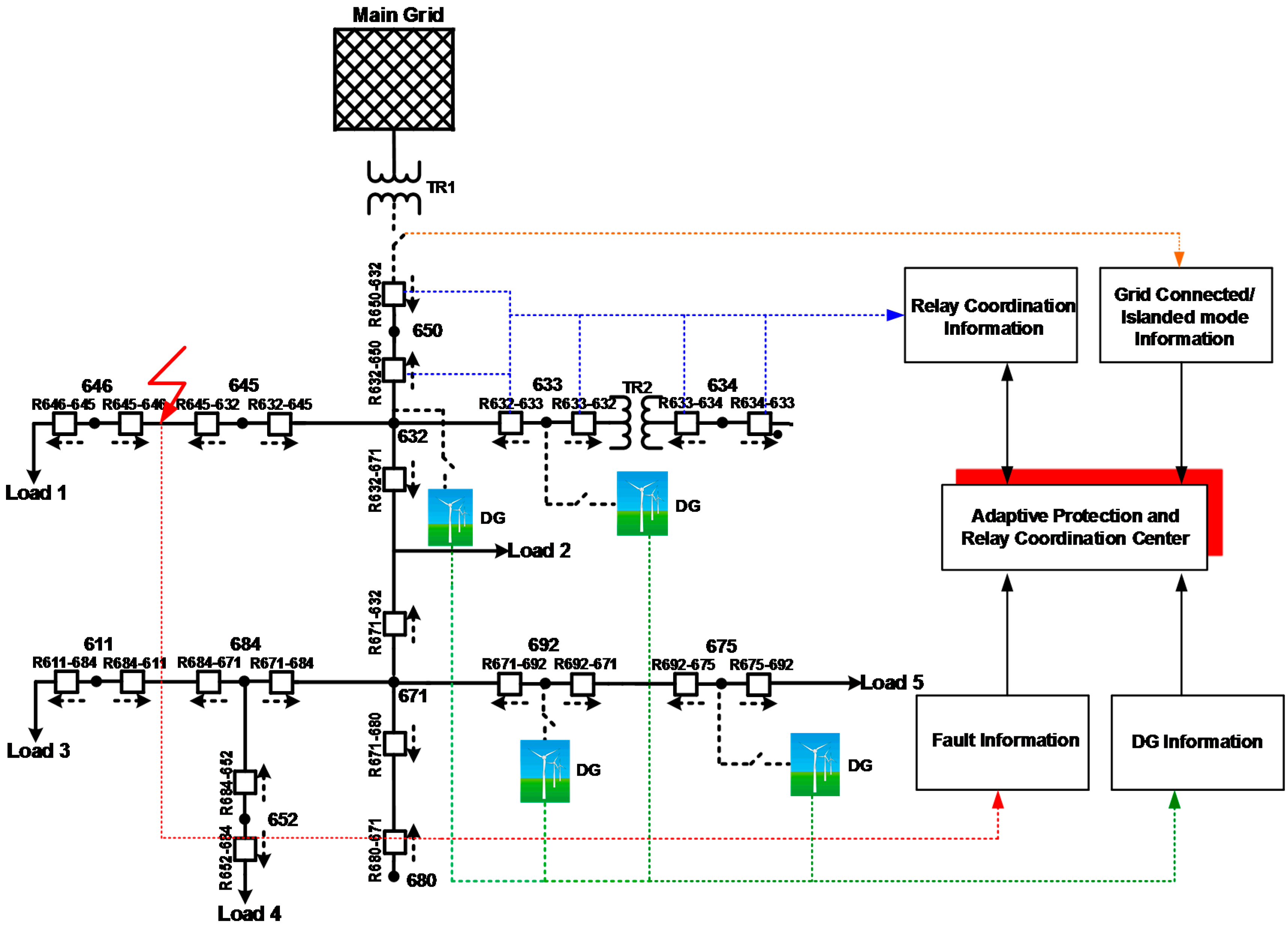
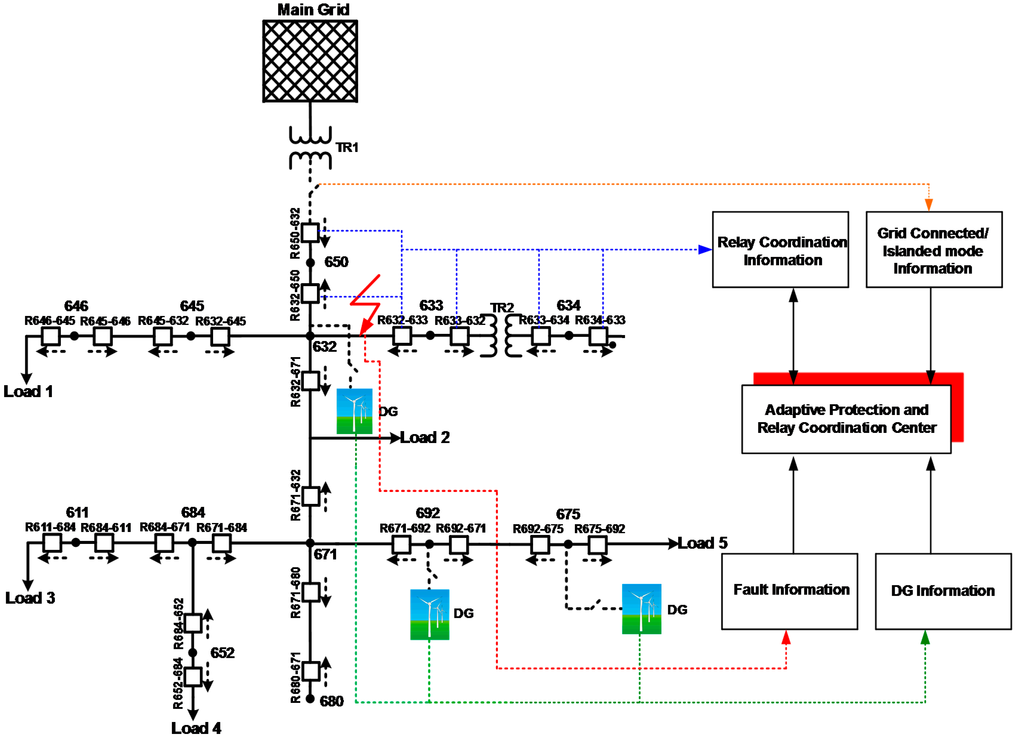
3.2. Scenario 2
The reference grid model is modified as in
Figure 5, and the new scenario study is conducted. The fault point in the system is selected between Buses 632-671 located in the middle of the line, and regarding the DGs connected to different points, the results are obtained as in
Table 7.
Similarly to Scenario 1, the adaptive protection scheme outperforms both the semi-adaptive and conventional schemes in grid-connected and islanded modes of operation. For instance, in the conventional scheme, the R675_692 relay that should not operate during such a fault trips in a system model where wind turbine-based DGs are connected to Buses 675 and 692. This leads to an unnecessary energy outage. On the other hand, the adaptive protection scheme allows the R362_671 relay to generate a tripping signal (0.4986 s) earlier than the conventional method ensuring the clearance of the system from the fault faster. Similar discussions can be provided also for grid-connected mode, which clearly presents the necessity of the adaptive protection method.
3.3. Scenarios 3–5
Lastly, the topologies regarding Scenarios 3–5 are given in
Figure 6,
Figure 7 and
Figure 8, respectively. Besides, the results of Scenarios 3–5, respectively given in
Table 8,
Table 9 and
Table 10, present similar results to the previous scenarios, and the effectiveness of the developed algorithm can be examined.
To apply the proposed strategy in a real distribution system the following components are required:
Microprocessor based relays.
A central computer system that executes the algorithm, stores the data from the sensors, estimates the system state and decides whether the settings of a relay should be changed.
Proper communication infrastructure between the central computer system and the relays, enabling fast and reliable convey of the settings to the relays.
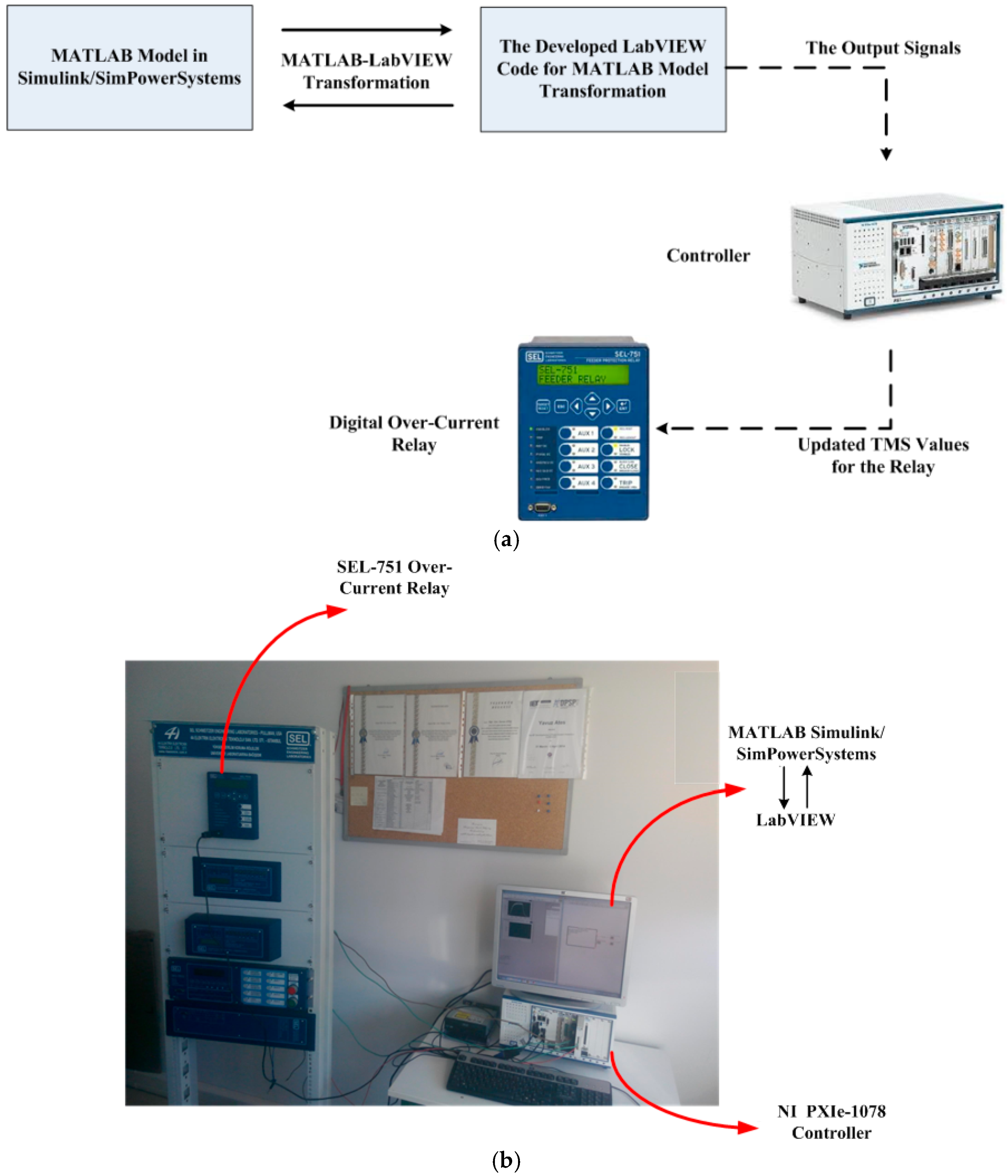
The studies in order to implement the proposed methodology in an experimental test system are currently under development, as shown in the developed test system demonstration in
Figure 9. The SEL-751 digital over-current relays (Schweitzer Engineering Laboratories, Pullman, WA, USA) and NI PXe-1078 real-time simulator/controller (National Instruments, Austin, TX, USA) are used within the test system. LabVIEW software (National Instruments) is used to transform the MATLAB model to the controller requirements. The initial results obtained with the proposed methodology are encouraging, since comparing the obtained results with the simulation results resulted in a sufficient correlation. More detailed results will be presented in future studies of the authors.
4. Conclusions
The adaptive protection schemes are likely to gain increasing importance together with the recent more complex structure of distribution systems in the presence of renewable energy-based DG penetration. Following this trend, in this study, an adaptive dynamic protection and relay coordination scheme was presented for a distribution system considering wind energy-based DGs.
The results were obtained for different scenarios, and the schemes, namely adaptive, semi-adaptive and conventional, were compared in terms of the protection effectiveness. It was observed that the adaptive method proposed in this study outperformed the other competitive schemes in both islanded and grid-connected operating modes and active DG status changes. The early or late tripping of relays is a concern for the effective operation of distribution systems, and together with the proposed methodology that increases the system performance in this regard, a more reliable and stable system with minimized outages can be obtained.
As a future study, it is planned to apply optimization techniques for relay settings’ determination and adaptive operation. Besides, the new threats of DGs to distribution protection schemes, such as blinding of feeder protection, sympathetic tripping, failed reclosing and recloser-fuse miscoordination, are already planned as a future study to enrich the operation of the proposed methodology. Moreover, different faults types, such as both symmetrical and different asymmetrical, can be further analyzed considering not only radial, but also alternative distribution system configurations (e.g., meshed).
Acknowledgments
This study is supported by The Scientific and Technological Research Council of Turkey Fund under Grant 111E142. Besides, this work was supported by FEDER funds through COMPETE and by Portuguese funds through FCT, under FCOMP-01-0124-FEDER-020282 (Ref. PTDC/EEA-EEL/118519/2010), UID/CEC/50021/2013 and SFRH/BPD/103744/2014. Also, the research leading to these results has received funding from the EU Seventh Framework Programme FP7/2007-2013 under grant agreement no. 309048 (project SiNGULAR).
Author Contributions
Yavuz Ates and Ali Rifat Boynuegri mainly contributed by realizing the simulation and experimental analyses. Besides, Mehmet Uzunoglu and Abdullah Nadar coordinated the overall studies through a research project and also contributed by their expertise on the distributed generation topic. Moreover, Recep Yumurtacı contributed by the expertise on protection and relay coordination. Lastly, Ozan Erdinc, Nikolaos G. Paterakis and João P. S. Catalão contributed by overall technical suggestions through the research steps and also contributed to the writing of the final research paper.
Conflicts of Interest
The authors declare no conflict of interest.
References
- Ma, J.; Mi, C.; Wang, T.; Wu, J.; Wang, Z.P. An Adaptive Protection Scheme for Distributed Systems with Distributed Generation. In Proceedings of the IEEE Power and Energy Society General Meeting, San Diego, CA, USA, 24–29 July 2011.
- Willis, H.L.; Scott, W.G. Distributed Power Generation Planning and Evaluation; Marcel Dekker: New York, NY, USA, 2000. [Google Scholar]
- Battaglini, A.; Lilliestam, J.; Haas, A.; Patt, A. Development of SuperSmart Grids for a More Efficient Utilisation of Electricity from Renewable Sources. J. Clean. Prod. 2009, 17, 911–918. [Google Scholar] [CrossRef]
- Cardenas, J.A.; Gemoets, L.; Rosas, J.H.A.; Sarfi, R. A Literature Survey on Smart Grid Distribution: An Analytical Approach. J. Clean. Prod. 2014, 65, 202–216. [Google Scholar] [CrossRef]
- Lund, T.P.; Mikkola, J.; Ypyä, J. Smart Energy System Design for Large Clean Power Schemes in Urban Areas. J. Clean. Prod. 2014, 103, 437–445. [Google Scholar] [CrossRef]
- Hacatoglu, K.; Dincer, I.; Rosen, M.A. A New Model to Assess the Environmental Impact and Sustainability of Energy Systems. J. Clean. Prod. 2014. [Google Scholar] [CrossRef]
- Javadian, S.A.M.; Haghifam, M.-R.; Bathaee, S.M.T.; Firoozabad, M.F. Adaptive Centralized Protection Scheme for Distribution Systems with DG Using Risk Analysis for Protective Devices Placement. Electr. Power Energy Syst. 2013, 44, 337–345. [Google Scholar] [CrossRef]
- Moslehi, K.; Kumar, R. A Reliability Perspective of the Smart Grid. IEEE Trans. Power Deliv. 2010, 1, 57–64. [Google Scholar]
- Barker, P.P.; de Mello, R.W. Determining the Impact of Distributed Generation on Power Systems: Part 1—Radial Distribution Systems. IEEE Trans. Power Deliv. 2000, 15, 486–493. [Google Scholar]
- Brahma, S.; Girgis, A. Development of Adaptive Protection Scheme for Distribution Systems with High Penetration of Distributed Generation. IEEE Trans. Power Deliv. 2004, 19, 56–63. [Google Scholar] [CrossRef]
- Chilvers, I.; Jenkins, N.; Crossley, P. Distance Relaying of 11 kV Circuits to Increase the Installed Capacity of Distributed Generation. IEE Proc. Gener. Transm. Distrib. 2005, 152, 40–46. [Google Scholar] [CrossRef]
- Dugan, R.C.; McDermott, T.E. Distributed Generation. IEEE Ind. Appl. Mag. 2002, 8, 19–25. [Google Scholar] [CrossRef]
- El Halabi, N.; García-Gracia, M.; Borroy, J.; Villa, J.L. Current Phase Comparison Pilot Scheme for Distributed Generation Networks Protection. Appl. Energy 2011, 88, 4563–4569. [Google Scholar] [CrossRef]
- Javadian, S.A.M.; Haghifam, H.-R.; Firoozabad, M.F.; Bathaee, S.M.T. Analysis of Protection System’s Risk in Distribution Networks with DG. Electr. Power Energy Syst. 2013, 44, 688–695. [Google Scholar] [CrossRef]
- Kawady, T.A.; Taalab, A.-M.I.; Ahmed, E.S. Dynamic Performance of the Power Differential Relay for Transmission Line Protection. Int. J. Electr. Power Energy Syst. 2010, 32, 390–397. [Google Scholar] [CrossRef]
- Doyle, M.T. Reviewing the Impacts of Distributed Generation on Distribution System Protection. In Proceedings of the IEEE Power Engineering Society Summer Meeting, Chicago, IL, USA, 25 July 2002; Volume 1, pp. 103–105.
- Elmarkabi, I.M. Control and Protection of Distribution Networks with Distributed Generators. Ph.D. Thesis, North Carolina State University, Raleigh, NC, USA, 2004. [Google Scholar]
- Ma, J.; Wang, X.; Zhang, Y.; Yang, Q.; Phadke, A.G. A Novel Adaptive Current Protection Scheme for Distribution Systems with Distributed Generation. Int. J. Electr. Power Energy Syst. 2012, 43, 1460–1466. [Google Scholar] [CrossRef]
- Kauhaniemi, K.; Kumpulainen, L. Impact of Distributed Generation on the Protection of Distribution Networks. In Proceedings of the Eighth IEE International Conference on Developments in Power System Protection, Amsterdam, The Netherlands, 5–8 April 2004; pp. 315–318.
- Rezaei, N.; Haghifam, M. Protection Scheme for a Distribution System with Distributed Generation Using Neural Networks. Int. J. Electr. Power Energy Syst. 2008, 30, 235–241. [Google Scholar] [CrossRef]
- Shahriari, S.A.A.; Varjani, A.Y.; Haghifam, M.R. Cost Reduction of Distribution Network Protection in Presence of Distributed Generation Using Optimized Fault Current Limiter Allocation. Int. J. Electr. Power Energy Syst. 2012, 43, 1453–1459. [Google Scholar] [CrossRef]
- Tuitemwong, K.; Premrudeepreechacharn, S. Expert System for Protection Coordination of Distribution System with Distributed Generators. Int. J. Electr. Power Energy Syst. 2011, 33, 466–471. [Google Scholar] [CrossRef]
- Singh, M.; Panigrahi, B.K.; Abhyankar, A.R.; Das, S. Optimal Coordination of Directional Over-current Relays Using Informative Differential Evolution Algorithm. J. Comput. Sci. 2014, 5, 269–276. [Google Scholar] [CrossRef]
- Chelliah, T.R.; Thangaraj, R.; Allamsetty, S.; Pant, M. Coordination of Directional Overcurrent Relays Using Opposition Based Chaotic Differential Evolution Algorithm. Electr. Power Syst. Res. 2014, 55, 341–350. [Google Scholar] [CrossRef]
- El-khattam, W.; Sidhu, T.S. Resolving the impact of distributed renewable generation on directional over-current relay coordination: A case study. IET Renew. Power Gener. 2009, 3, 415–425. [Google Scholar] [CrossRef]
- El-Zonkoly, A.M. Fault Diagnosis in Distribution Networks with Distributed Generation. Electr. Power Syst. Res. 2011, 81, 1482–1490. [Google Scholar] [CrossRef]
- Abdelaziz, A.Y.; Talaat, H.E.A.; Nosseir, A.I.; Hajjar, A.A. An adaptive protection scheme for optimal coordination of overcurrent relays. Elect. Power Syst. Res. 2002, 61, 1–9. [Google Scholar] [CrossRef]
- Noghabi, A.S.; Mashhadi, H.R.; Sadeh, J. Optimal coordination of directional overcurrent relays considering different network topologies using interval linear programming. IEEE Trans. Power Del. 2010, 25, 1348–1354. [Google Scholar] [CrossRef]
- By, L.C.; Khodayar, M.E.; Shahidehpour, M. Adaptive Protection System for Microgrids: Protection Practices of a Functional Microgrid System. IEEE Electr. Mag. 2014, 2, 66–80. [Google Scholar]
- Ezzeddine, M.; Kaczmarek, R. A novel method for optimal coordination of directional overcurrent relays considering their available discrete settings and several operation characteristics. Electr. Power Syst. Res. 2011, 81, 1475–1481. [Google Scholar] [CrossRef]
- Ezzeddine, M.; Kaczmarek, R.; Iftikhar, M.U. Coordination of directional overcurrent relays using a novel method to select their settings. IET Gener. Transm. Distrib. 2011, 5, 743–750. [Google Scholar] [CrossRef]
- Papaspiliotopoulos, V.; Korres, G.; Maratos, N. A novel quadratically constrained quadratic programming method for optimal coordination of directional overcurrent relays. IEEE Trans. Power Deliv. 2015. [Google Scholar] [CrossRef]
- Coffele, F.; Booth, C.; Dyśko, A. An Adaptive Overcurrent Protection Scheme for Distribution Networks. IEEE Trans. Power Deliv. 2015, 30, 561–568. [Google Scholar] [CrossRef] [Green Version]
- Mozina, C.J. Impact of Green Power Distributed Generation. IEEE Ind. Appl. Mag. 2010, 16, 55–62. [Google Scholar] [CrossRef]
- Girgis, A.; Brahma, S. Effect of Distributed Generation on Protective Device Coordination in Distribution System. In Proceedings of the 2011 Large Engineering Systems Conference on Power Engineering, Halifax, NS, Canada; 2011; pp. 115–119. [Google Scholar]
- Butler-Purry, K.L.; Marotti, M. Impact of Distributed Generators on Protective Devices in Radial Distribution Systems. In Proceedings of the 2005/2006 IEEE/PES Transmission and Distribution Conference and Exhibition, Dallas, TX, USA, 21–24 May 2006; pp. 87–88.
- Najy, W.K.A.; Zeineldin, H.H.; Wei, L.W. Optimal protection coordination for microgrids with grid-connected and islanded capability. IEEE Trans. Ind. Electr. 2013, 60, 1668–1677. [Google Scholar] [CrossRef]
- Zeineldin, H.H.; Mohamed, Y.A-R.I.; Khadkikar, V.; Pandi, V.R. A protection coordination index for evaluating distributed generation impacts on protection for meshed distribution systems. IEEE Trans. Smart Grid 2013, 4, 1523–1532. [Google Scholar] [CrossRef]
- Sachdev, M.S.; Sidhu, T.S.; Talukdar, B.K. Topology Detection for Adaptive Protection of Distribution Networks. In Proceedings of the International Conference on Energy Management and Power Delivery, Singapore, 21–23 November 1995; pp. 445–450.
- Chowdhury, A.A.; Chowdhury, S.; Ten, C.F.; Crossley, P.A. Islanding Operation of Distributed Generators in Active Distribution Networks. In Proceedings of the 43rd Universities Power Engineering Conference, Sydney, Australia, 1–4 September 2008.
- Pukar, M.; Chen, Z.; Bak-Jensen, B.; Bak, C.L. A simple adaptive overcurrent protection of distribution systems with distributed generation. IEEE Trans. Smart Grid 2011, 2, 428–437. [Google Scholar]
- Tang, G.; Iravani, M.R. Application of a Fault Current Limiter to Minimize Distributed Generation Impact on Coordinated Relay Protection. In Proceedings of the International Conference Power System Transients, Montreal, QC, Canada, 19–23 June 2005.
- Agheli, A.; Abyaneh, H.A.; Chabanloo, R.M.; Dezaki, H.H. Reducing the Impact of DG in Distribution Networks Protection Using Fault Current Limiters. In Proceedings of the 4th International Power Engineering and Optimization Conference (PEOCO), Shah Alam, Malaysia, 23–24 June 2010; pp. 298–303.
- Baran, M.; El-Markabi, I. Adaptive Over Current Protection for Distribution Feeders with Distributed Generators. In Proceedings of the Power Systems Conference and Exposition, New York, NY, USA, 10–13 October 2004; pp. 715–719.
- Schaefer, N.; Degner, T.; Shustov, A.; Keil, T.; Jaeger, J. Adaptive Protection System for Distribution Networks with Distributed Energy Resources. In Proceedings of the Developments in Power System Protection (DPSP 2010), Manchester, UK, 29 March–1 April 2010.
- Cheung, H.; Hamlyn, A.; Yang, C.; Cheung, R. Network-based Adaptive Protection Strategy for Feeders with Distributed Generations. In Proceedings of the IEEE Canada Electrical Power Conference, Montreal, QC, Canada, 25–26 October 2007; pp. 514–519.
- Jennet, K.I.; Booth, C.D.; Coffele, F.; Roscoe, A.J. Investigation of the sympathetic tripping problem in power systems with large penetrations of distributed generation. IET Gener. Transm. Distrib. 2015, 9, 379–385. [Google Scholar] [CrossRef]
- DSASR, Distribution System Analysis Subcommittee Report, Radial Distribution Test Feeders. Available online: http://ewh.ieee.org/soc/pes/dsacom/testfeeders.html (accessed on 2 October 2014).
- Ates, Y.; Uzunoglu, M.; Karakas, A.; Boynuegri, A.R.; Nadar, A.; Dag, B. Implementation of Adaptive Relay Coordination in Distribution Systems Including Distributed Generation. J. Clean. Prod. 2016, 112, 2697–2705. [Google Scholar] [CrossRef]
- AREVA T&D Automation & Information Systems. Overcurrent Protection for Phase and Earth Faults. In Network Protection & Automation Guide; AREVA: Paris, France, 2005; pp. 122–151. [Google Scholar]
- Working Group of G-7 of the Relay Standards Committee of the Power Systems Relaying Committee. IEEE Standard Inverse-Time Characteristic Equations for Overcurrent Relays. IEEE Trans. Power Deliv. 1999, 14, 868–872. [Google Scholar]
© 2016 by the authors; licensee MDPI, Basel, Switzerland. This article is an open access article distributed under the terms and conditions of the Creative Commons Attribution (CC-BY) license (http://creativecommons.org/licenses/by/4.0/).


