Article

The Study of Fuzzy Proportional Integral Controllers Based on Improved Particle Swarm Optimization for Permanent Magnet Direct Drive Wind Turbine Converters

1
School of Mechanical, Electronic and Control Engineering, Beijing Jiaotong University, Beijing 100044, China
2
School of Mechanical, Materials and Mechatronic Engineering, University of Wollongong, Northfields Ave, Wollongong, NSW 2522, Australia
*
Authors to whom correspondence should be addressed.
These authors contributed equally to this work.
Energies 2016, 9(5), 343; https://doi.org/10.3390/en9050343
Submission received: 5 January 2016 / Revised: 14 April 2016 / Accepted: 26 April 2016 / Published: 6 May 2016

Abstract

:
In order to meet the requirements of high precision and fast response of permanent magnet direct drive (PMDD) wind turbines, this paper proposes a fuzzy proportional integral (PI) controller associated with a new control strategy for wind turbine converters. The purpose of the control strategy is to achieve the global optimization for the quantization factors, ke and kec, and scale factors, kup and kui, of the fuzzy PI controller by an improved particle swarm optimization (PSO) method. Thus the advantages of the rapidity of the improved PSO and the robustness of the fuzzy controller can be fully applied in the control process. By conducting simulations for 2 MW PMDD wind turbines with Matlab/Simulink, the performance of the fuzzy PI controller based on the improved PSO is demonstrated to be obviously better than that of the PI controller or the fuzzy PI controller without using the improved PSO under the situation when the wind speed changes suddenly.

Graphical Abstract

1. Introduction

With the decrease in conventional energy reserves and increased concerns about environment pollution in recent years, it has become a primary mission for most countries to take actions to find new kinds of clean and renewable energy for use. Wind power is one of the main clean and renewable energy sources, and its penetration in the energy market has kept increasing in the past 20 years. The US Department of Energy aims to achieve 20% of wind energy penetration in the utility market by the end of 2030 [1]. The European Wind Energy Association reported that the goal is to generate 26%–34% of the electricity from wind by 2030 [2]. China’s wind industry is forecasted to reach 216.6 gigawatts (GW) in 2020 and at least 310.2 GW of installed capacity by 2030 [3]. The historic increase trend of wind energy is illustrated in [4]. It is undoubtable that the global wind energy market will steadily grow in the future.
Considering the large wind turbines installed worldwide, they are typically classified into two types: one is with a geared generator concept, such as those equipped with doubly-fed induction generators (DFIGs) and the other is based on a direct drive mechanism such as those using permanent magnet generators. Each of them has advantages and disadvantages, as discussed in [5]. Their comparison in general was given in [4]. The direct drive wind energy conversion system (WECS) based on permanent magnet synchronous generators (PMSGs) is one of the promising wind power generation systems. Its advantages include higher reliability, better thermal characteristics, lower mass per kilowatt output power, lower weight, and a smaller generator size [4]. A typical PMSG wind power system configuration is illustrated in Figure 1. The wind turbine converts the kinetic energy of the wind into mechanical energy and the mechanical energy is converted into electrical power through the PMSG. The output of the PMSG is connected to the grid through a full-scale back-to-back converter. This converter system is composed of both the generator side converter and the grid side converter. It is an AC/DC/AC converter.
As a key component in the interconnection of the generator and power grid in the permanent magnet direct drive (PMDD) wind turbines, the converter is supposed to not only control the generator but also transfer high quality power to the grid, and it is also required to realize the low voltage ride-through if needed [6]. Therefore, it is necessary to have an effective control strategy for the converter. Generally, the generator side converter and the grid side converter are controlled separately. The generator side converter is used to control the generator speed based on the maximum power theory by taking into account the generator current, consequently the DC voltage at the dc link will vary according to the wind speed. The grid side converter is to control the DC voltage by taking into account the grid voltage and current. Both converters are usually controlled by the proportional integral (PI) method [7], which is simple and practical. PI control, however, doesn’t have parameter optimization functions. The parameters of a PI controller cannot be adjusted in response to changes in the external conditions. Therefore, many scholars have made efforts to investigate new control methods. New control techniques and strategies associated with different converter architectures have been proposed and studied for different purposes. These new control techniques include fuzzy logic based control [8], adaptive control [9], linear quadratic control [10] like the disturbance accommodating control (DAC) [11] developed by the National Renewable Energy Laboratory (NREL) in the U.S.A. and tested in the Controls Advanced Research Turbine (CART) [12], quantitative feedback theory (QFT) control [13], Linear Parameter Varying (LPV) control [14], H based control [15], sliding mode variable structure cascade control [16], state feedback control [17], predictive control [18], artificial neural network (ANN)-based control [19], and different hybrid approaches such as combination of fuzzy model and genetic algorithm (GA) and recursive least-squares (RLS) optimization methods, combination of fuzzy ANN and particle swarm optimization (PSO) algorithm, hybrid of classic control and evolutionary strategy algorithm, hybrid of ANN and fuzzy inference system (FIS), combination of PI and sliding mode control (SMC), integration of model predictive control (MPC) and evolutionary computation, embedding fuzzy controller into model reference adaptive control framework and so on [20]. The advantages and shortcomings of each of these control techniques are summarized in Table 1.
Among the control techniques summarized in Table 1, fuzzy logic control is a basic modern control method that is often used. Its advantages include that it does not require complicated mathematical calculations and it can cope well with uncertainties and nonlinearities, as discussed in many research articles. Reference [25] is one of them, for example, where PI and fuzzy controllers were tested to extract the maximum power from the wind. Simulation results were given to show the performance of the proposed fuzzy control system in maximum power points tracking (MPPT) in a WECS under various wind conditions. In [26], the fuzzy logic based voltage and speed controller for autonomous PMSG-WECS was discussed, where the dynamic performance of the proposed controller was tested under the situations of decreasing, increasing and constant wind speed with balanced/unbalanced non-linear load. In [8], a fuzzy-logic based MPPT method for a standalone wind turbine system was proposed. The hill climb searching (HCS) method was used to achieve the MPPT of the PMSG wind turbine system. In [27], two fuzzy controllers were proposed. The first one is dedicated to the MPPT of a variable speed PMSG wind turbine and the second fuzzy controller has the objective to manage both the production and the storage of electricity for optimum performance of the system in respect of load demand. A sliding mode voltage control strategy was proposed in [28] for capturing the maximum wind energy based on fuzzy logic control, which was illustrated to have higher overall control efficiency than the conventional proportional integral derivative (PID) control. In [29], fuzzy logic is implemented to determine the torque command by using the inertia of a wind turbine. The inputs of the fuzzy logic are given by the operating point of the rotational speed of the PMSG and the difference between the wind turbine torque and the generator torque. With this method, the generator torque is smoothed and kinetic energy generated by the inertia of the wind turbine is used to smooth the PMSG power fluctuations. A novel control strategy based on fractional-order PIμ controller for the variable-speed operation of wind turbines with PMSG and full-power converters is given in [30] where the SMC strategy is applied as it can present some attractive features in wind turbine control and operation. One of these features is the robustness to parametric uncertainties of the WECS as well as to grid disturbances [31]. Li et al. [32] presented a direct-current based d-q vector control technique by integrating fuzzy, adaptive and traditional PID control technologies into an optimal control configuration. The proposed control approach was demonstrated to have superior performance in various aspects and to be effective not only in achieving the desired PMSG control objectives but also in improving the overall system performance. A short technical review of WECSs is given in [33] where the control strategies of controllers for both DFIG-WECS and PMSG-WECS and various MPPT technologies for efficient production of energy from the wind are discussed. It is clearly shown that to develop new control strategies for various controllers applied to different platforms of wind turbines is still a developing trend. It is noted that the most suitable and optimized solutions/approaches to extracting maximum power of the installed systems are each of an ad-hoc nature, rather than generalized solutions [33].
In order to meet the requirements of high precision and fast response of PMDD wind turbines, this present paper proposes a fuzzy PI controller based on an improved PSO. Different from other references like [20] and [34], four parameters of the fuzzy controller including the quantization factors of ke and kec, and scale factors of kup and kui, are optimized at the same time using the improved PSO. The parameters of the fuzzy controller can be adjusted in real time according to environment changes to improve the robustness and precision of the controller for achieving the control target. Overshoot and regulating time are two indicators for evaluating the merits of the controller when wind speed step changes occur [35]. As wind speed varies continuously, Root-Mean-Square Error (RMSE) is used to measure the deviation of the calculated values with the reference value. The validity of the control algorithm developed has been verified through simulation for a 2 MW PMSG-WECS.

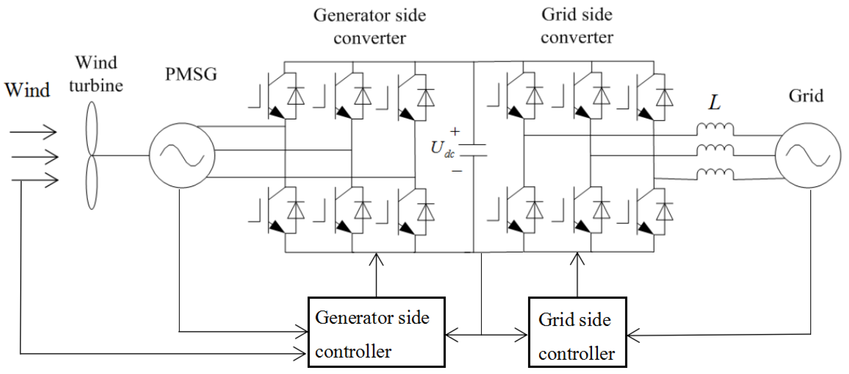
2. Analysis of Converter Control Strategy

The running of the PMDD wind power generation system can be divided into three states including starting, MPPT and constant power production. This paper focuses on the MPPT stage when the wind speed is mainly below the rated wind speed. At this time, the rotational speed of the generator needs real-time adjustment according to the wind speed so as to realize the tracking control of maximum power [36]. For higher efficiency of the wind turbines, the rotor flux orientation vector control method is applied to the generator side converter control. At the same time, when the wind speed and external circumstances change, the voltage orientation control strategy is used to control the grid side converter in order to maintain the voltage stability of the DC side capacitance and realize the decoupling control of active power and reactive power. Space vector pulse width modulation (SVPWM) [37] is adopted in both the generator side converter and the grid side converter control.

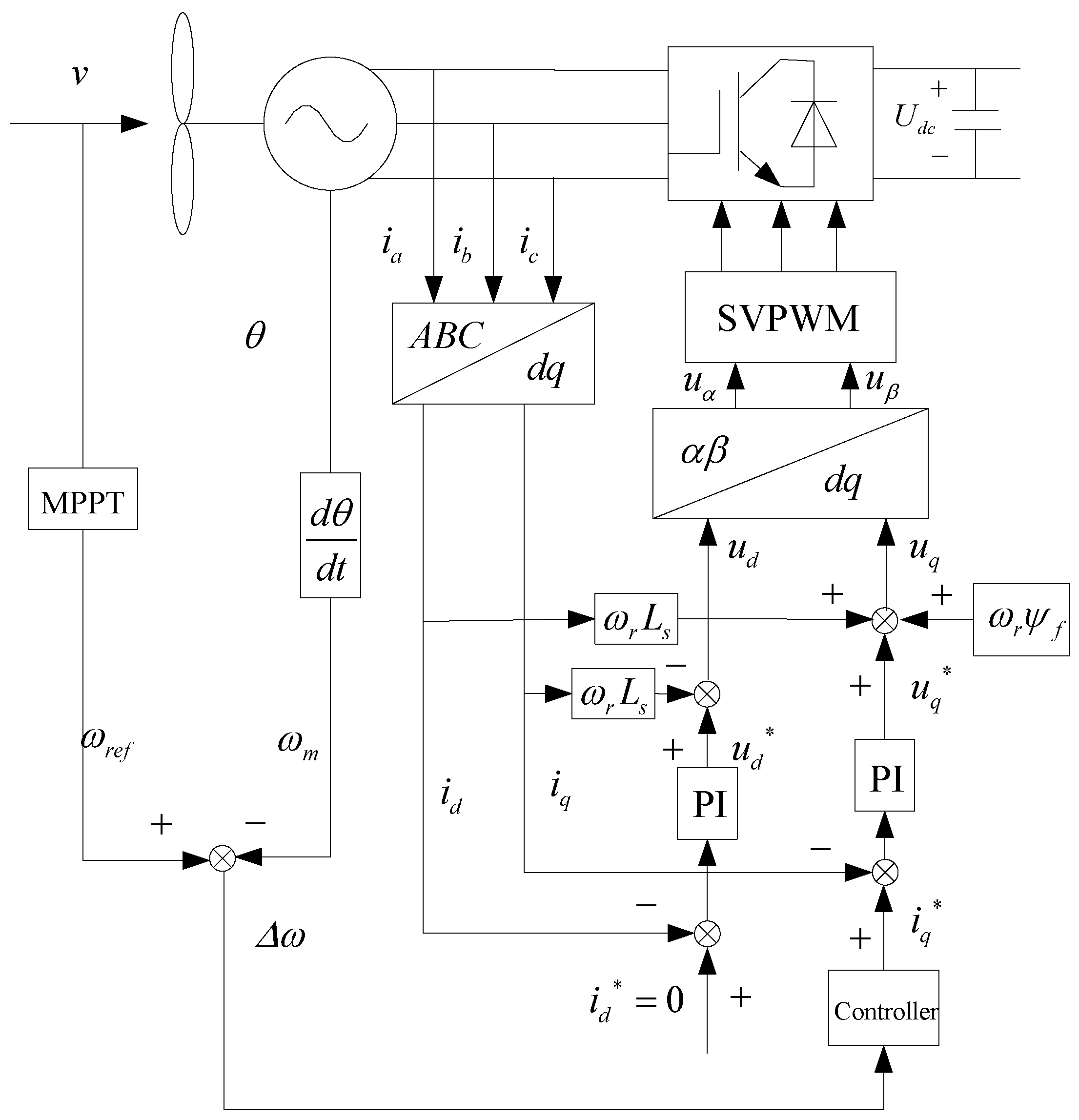
2.1. The Control Strategy of Generator Side Converter

The generator side converter generally adopts vector control based on rotor flux orientation [38]. The d-axis is oriented to the direction of the rotor flux, and q-axis is 90° ahead of d-axis. Assuming the direction of current flowing into the generator is positive, the d-axis and q-axis components of inductance of the stator winding are equal to Ls, the voltage equation of the stator of PMSG in synchronous rotating d-q coordinate system can be expressed as:
{ u d = R s i d + L s d i d d t ω r L s i q u q = R s i q + L s d i q d t + ω r L s i d + ω r ψ f
where, ud, uq, id, and iq are d-axis and q-axis components of the stator’s terminal voltage and current; Rs and Ls are resistance and inductance of stator winding, respectively; ωr is electrical angular velocity of generator; and ψf is flux linkage of the rotor.
When id is zero (i.e., id* = 0), the electromagnetic torque of PMSG, Te, is:
T e = 3 2 N p i q ψ f
where, Np is the pole pairs of generator.
PMDD wind turbines don’t have gear boxes. The wind wheel is directly connected with the generator rotor through the rotation shaft so that the generator rotor speed is equal to the speed of the wind wheel. The mathematical model of transmission system of PMDD wind turbines can be expressed as:
d ω m d t = 1 J ( T e T m B ω r )
where, ωm is mechanical angular velocity of rotor; J is moment of inertia of rotor; B is damping coefficient; and Tm is mechanical torque of wind turbine.
Equation (2) shows that the electromagnetic torque Te can be controlled by controlling iq. Equation (3) shows that the rotor speed ωm can be further controlled by controlling Te to realize the tracking control of maximum power.
Equation (1) gives that the stator currents, id and iq, are coupled with each other. The precise linearization control can be achieved by decoupling of id and iq through the feed-forward compensation of ωr Ls iq and −ωr (Ls id + ψf). Define:
{ u d * = R s i d + L s d i d d t = u d + ω r L s i q u q * = R s i q + L s d i q d t = u q ω r L s i d ω r ψ f
They can be calculated through the PI controller as:
{ u d * = k pd ( i d * i d ) + k id ( i d * i d ) d t u q * = k pq ( i q * i q ) + k iq ( i q * i q ) d t
where, id* is the current reference value of id, and kpd, kid, kpq and kiq are constants.
The control of the generator side converter is designed as shown in Figure 2. Using the vector control strategy of rotor flux orientation with id* = 0, the double-closed loop control system including outer speed loop and inner current loop can be established. To obtain good dynamic performance, the new proposed controller is adopted in the speed closed-loop and PI controller is adopted in the current closed-loop. The speed ωref can be obtained according to the best tip-speed-ratio λoptopt = ωref R/v, where R is radius of wind turbine rotor, v is wind speed); and then compared with the measured speed, ωm. The current reference value iq* can be obtained by the speed loop controller through adjusting the electromagnetic torque. Through the actually measured phase current, id and iq can be calculated through the Clarke transform and Park transform. After comparing id* with id, iq* with iq; the deviations are adjusted by the inner current loop of PI controller. The voltages, ud* and uq*, are then obtained, and ud and uq can be calculated. After conversion, uα and uβ can be known. In such a way as mentioned above, the generator side converter can be controlled through SVPWM.

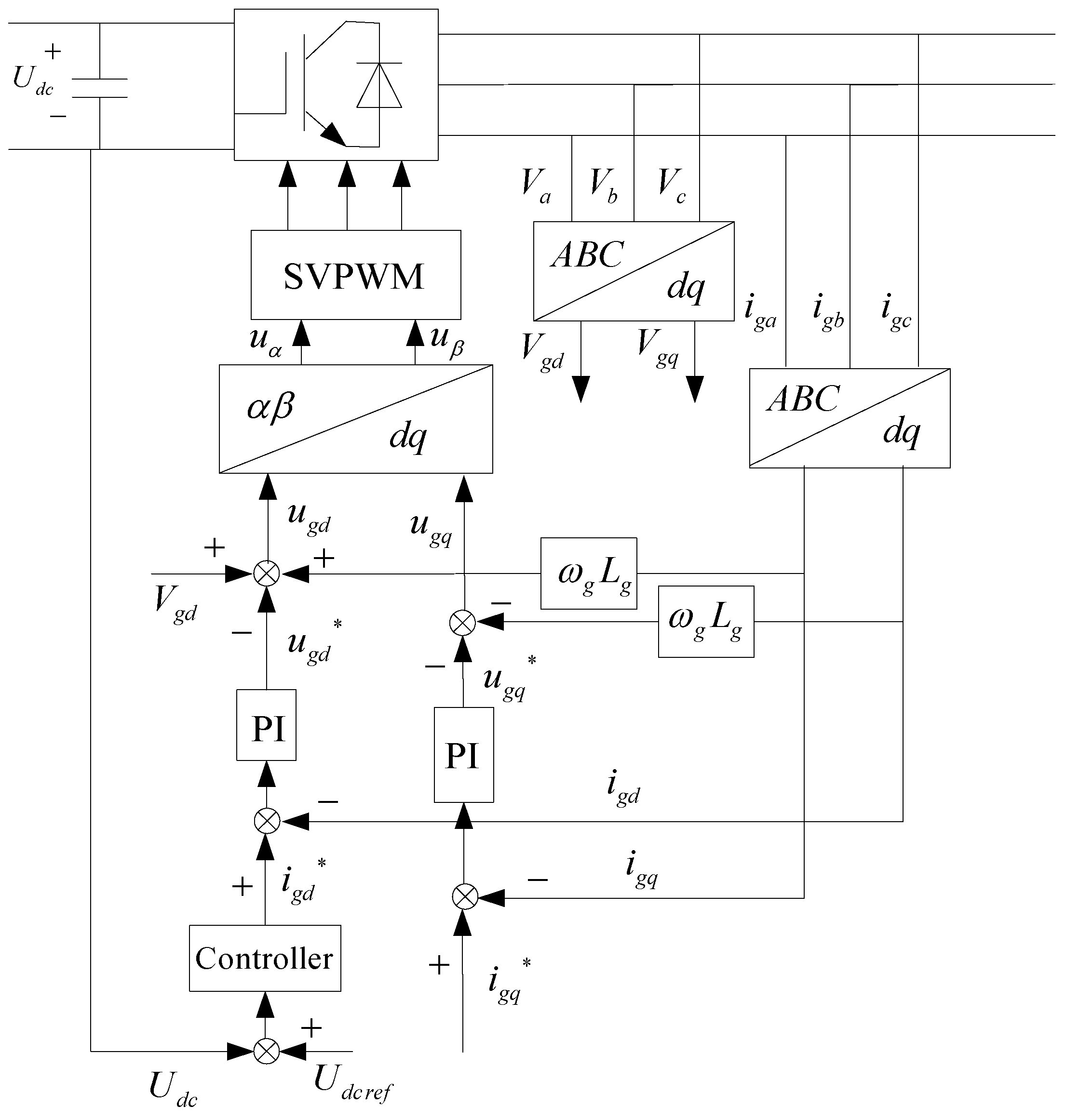
2.2. The Control Strategy of Grid Side Converter

For the grid side converter, this present paper adopts an oriented vector control technique based on the grid voltage. The basic control objectives are: (1) ensuring the stability of DC voltage and (2) ensuring the power up to the standard to incorporate into the grid.
In this study, the direction of grid side voltage vector is selected as d axis and 90° ahead of the direction of the voltage vector is as q axis. Then the voltage equation of grid side converter can be written as follows [39]:
{ u gd = L g d i gd d t R g i gd + ω g L g i gq + V gd u gq = L g d i gq d t R g i gq ω g L g i gd + V gq
where, Rg and Lg are the grid side equivalent resistance and inductance, respectively; ugd and ugq are the control voltage components of d-axis and q-axis, respectively, in grid side converter; igd and igq are grid side current components of d-axis and q-axis, respectively; Vgd and Vgq are the grid voltage components of d-axis and q-axis, respectively; ωg is synchronous electrical angular velocity of the grid.
For Vgq = 0 and Vgd = |Vg|, the active power and reactive power delivered to the power grid can be expressed as:
{ P s = 3 2 ( V gd i gd + V gq i gq ) = 3 2 V gd i gd Q s = 3 2 ( V gq i gd V gd i gq ) = 3 2 V gd i gq
Regardless of converter power loss, the DC side capacitor voltage can be expressed as:
C U dc d U dc d t = P gen P s
where, C is capacity value; Udc is voltage of the DC side capacitor; Pgen is the active power output of the generator side converter.
From Equations (7) and (8), it is known that the active power can be controlled by controlling the d-axis component, igd, DC voltage is further controlled, and finally the stability of DC voltage is realized. The output reactive power can be controlled by controlling the q-axis component, igq. If igq is zero, the control of unity-power factor can be established.
Equation (6) shows that igd and igq are coupled with each other. Decoupling control of igd and igq can be realized by feed-forward compensation of −(ωg Lg igq + Vgd) and ωg Lg igd (Vgq = 0), which is similar to the control of generator side converter. Define:
u gd * = L g d i gd d t + R g i gd u gq * = L g d i gq d t + R g i gq
They can also be calculated through PI controller as shown below:
{ u gd * = k pgd ( i gd * i gd ) + k igd ( i gd * i gd ) d t u gq * = k pgq ( i gq * i gq ) + k igq ( i gq * i gq ) d t
where, kpgd, kigd, kpgq and kigq are selected constants of PI controller.
The control of grid side converter is designed as shown in Figure 3. Using the grid voltage orientation control strategy, the grid side control is a double-closed loop system including an outer voltage loop and inner current loop. The proposed controller is adopted in the voltage closed loop and PI controller is adopted in the current closed-loop. Through the comparison of DC bus voltage Udc with the given reference voltage, Udcref, the current igd* can be obtained by adjusting the controller. igd and igq can be set up through transforming of the converter output current. For igq* = 0, ugd* and ugq* can be obtained. Similarly, Vgd can be obtained through transformation of the three-phase voltages Va, Vb and Vc; and then the output voltages ugd and ugq can be calculated. After conversion, uα and uβ can be obtained. In such a way, the grid side converter can be controlled through SVPWM.

3. Fuzzy PI Controller of the Converter Based on Improved Particle Swarm Optimization

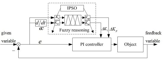
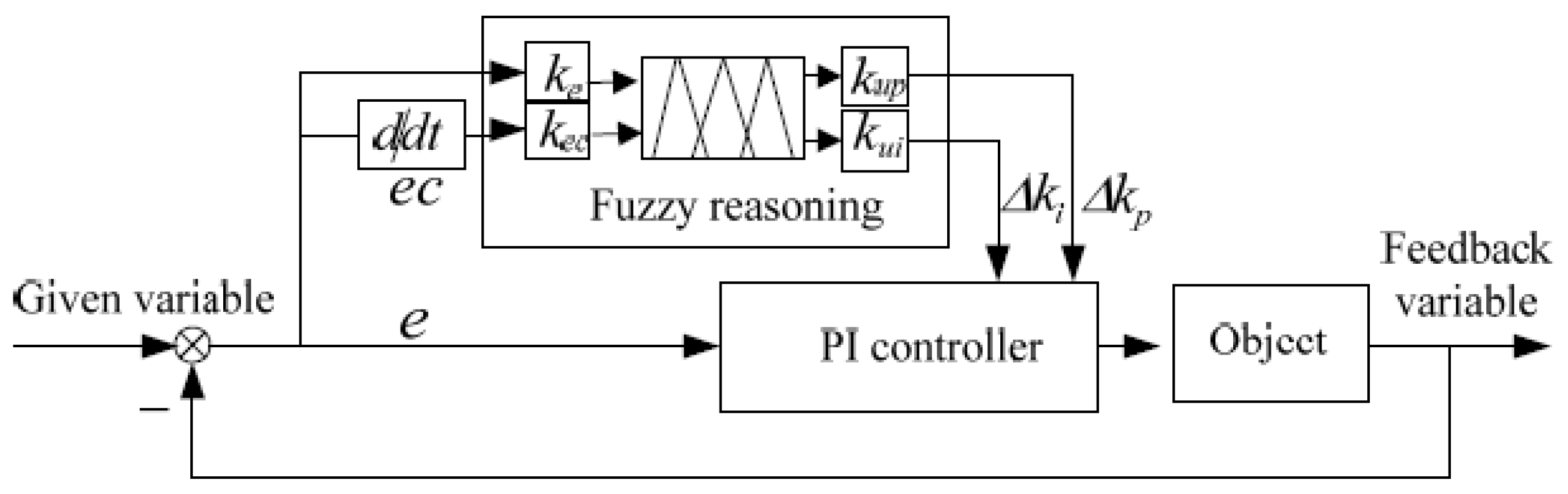
3.1. The General Fuzzy PI Controller

The “controller” as shown in Figure 2 and Figure 3 can be a PI controller, fuzzy PI controller or another new type of controller (like the fuzzy PI controller based on improved PSO). As mentioned above, the PI controller is simple and practical; however, it doesn’t have parameter optimization functions. In order to overcome the shortcomings of the PI controller, people usually use the fuzzy PI controller in the converter outer loop. The general structure of the fuzzy PI controller is shown in Figure 4. In order to achieve good control performance, the fuzzy PI controllers are designed for the generator side converter and the grid side converter. They both have two inputs and two outputs. The error and the error rate of the reference speed and the actual speed are the inputs to the generator side controller and the outputs are the variations of the speed loop PI parameters. The error and the error rate of the reference voltage and the actual voltage are the inputs to the grid side controller and the outputs are the variations of the voltage loop PI parameters. The membership functions of the controllers all adopt triangle membership functions. After determining the reasonable quantization factors and scale factors of input variables and output variables, the parameters of PI controller based on the fuzzy rules can be adjusted. In this paper, the quantization factors are represented by ke and kec, and the scale factors are expressed by kup and kui, respectively, see Figure 4.
The fuzzy PI controller does not require a precise mathematical model of controlled object, and is suitable for nonlinear systems. It has strong robustness with appropriate fuzzy control rules [26], but the fixed fuzzy control is usually not the best under all kinds of states due to the instability of the system input. Thus the fuzzy control rules or parameters need to be automatically adjusted and modified during operation in order to get the best control [40], which, however, cannot be achieved by a general fuzzy PI controller. Therefore, in this paper, the fuzzy control parameters (quantization factors of ke and kec, scale factors of kup and kui) are dynamically regulated using improved PSO for the fuzzy controller as described below. The designed controller is called fuzzy PI controller based on IPSO, which ensures the fuzzy controller will have optimal parameters automatically when the wind changes suddenly.

3.2. Improved Particle Swarm Optimization

As a new kind of global optimization algorithms, PSO was first proposed by Eberhart and Kennedy in 1995 [41]. Compared with other optimization techniques such as the ones based on genetic algorithms (GA) and ANNs, PSO has the merits of high search speed, high efficiency, easy to find the optimal solution, less set parameters, etc. It has been widely utilized due to its simple structure. The PSO as well as the PSO combined with fuzzy logic or genetic algorithms have been reported to be applied to power systems for various purposes, for example, for reactive power planning [42], Automatic Generation Control (AGC) of multi-area power systems with different energy resources [43], compensation of parametric and non-parametric uncertainties arising in modern power systems [44], enhancing power quality [45], damping of power system oscillations [46], and long-term generator maintenance scheduling [47]. The application of PSO to wind turbine control problems has been mentioned [48], but the research work found is limited.
The main idea of the PSO is to find the optimal solution of a complicated problem through iterations by initialization of a group of random particles. The particles update themselves by tracking two extrema in each iteration. One is the optimal solution produced by the self-iteration of particles namely individual extremum pbest and the other is the globally optimal solution, namely the global extremum gbest.
The position and velocity of particles are updated according to the following equations:
V ( k + 1 ) = V ( k ) + c 1 r 1 ( k ) ( p best ( k ) P ( k ) ) + c 2 r 2 ( k ) ( g best ( k ) P ( k ) )
P ( k + 1 ) = P ( k ) + V ( k + 1 )
where V is velocity of the particle; c1 and c2 are learning factors (in general, c1 = c2 = 2); r1 and r2 are random numbers between 0 and 1; P is position of the particle; and k is the current iteration number.
The previous research shows that the optimization effect becomes better when the basic velocity V is multiplied by the inertia weight coefficient w [49], so that the PSO formula of the velocity can be written as:
V ( k + 1 ) = w V ( k ) + c 1 r 1 ( k ) ( p best ( k ) P ( k ) ) + c 2 r 2 ( k ) ( g best ( k ) P ( k ) )
In the initial stage of optimization, a large inertia weight is beneficial to strengthening the global search ability of the algorithm; but in the later stages of optimization, a small inertia weight can strengthen the local search ability. This present paper adopts the method of calculating the inertia weight coefficient, w, according to number of iterations, k:
w ( k ) = w max w max w min N × k
where, wmax is the maximum and wmin is the minimum value of the inertia weight coefficient; N is the maximum number of iterations.
In the same way, in order to allow the algorithm to search in the whole optimization space and avoid falling into local minima, and enhance the algorithm convergence speed and accuracy in the late, this present paper adjusts the learning factors in the searching process according to the following:
c 1 = c 1 max ( c 1 max c 1 min ) N × k c 2 = c 2 min + ( c 2 max c 2 min ) N × k
where, cmax is the maximum and cmin is the minimum value of the corresponding factor, c.
Here, an improved PSO (IPSO) is defined by Equation (13) associated with Equations (12), (14) and (15). During the updating, the particle position P and velocity V are restricted in the allowable range. When the maximum number of iterations or the performance index is reached, the output gbest is the global optimal solution.

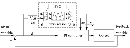
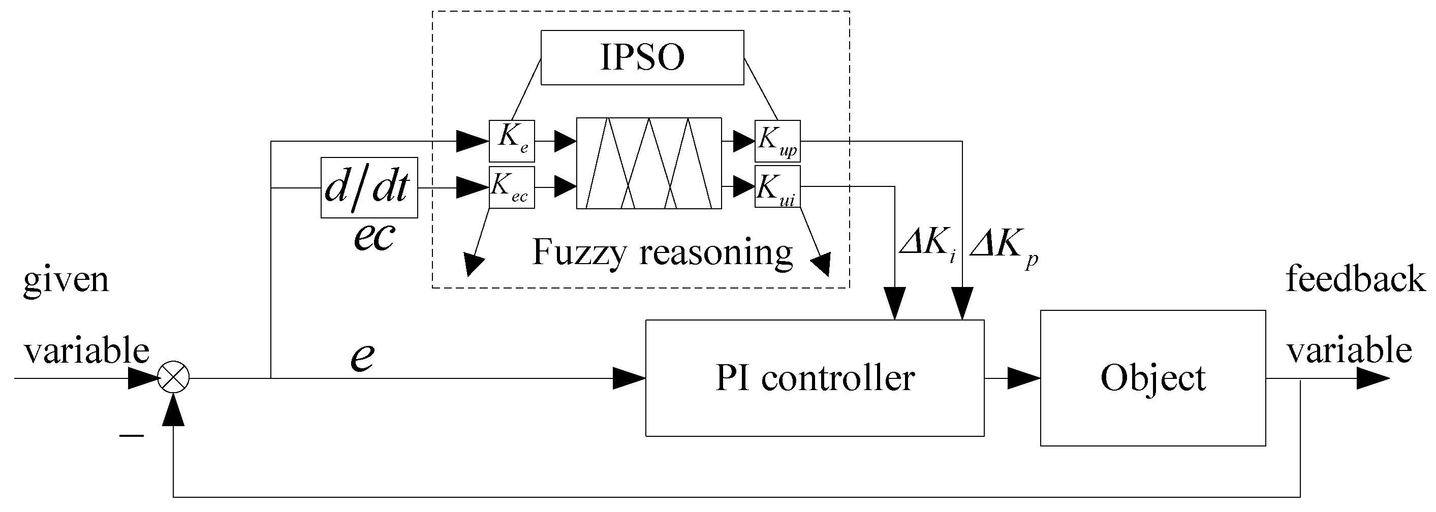
3.3. The Design of Fuzzy PI Controller Based on Improved Particle Swarm Optimization

The structure of an adaptive fuzzy PI controller based on IPSO is shown in Figure 5. The specific steps of realization of the PSO are as follows [50]:
(1)
Initializing the particle swarm. The initial position and velocity of every particle are randomly generated in the allowable range. Then the individual extremum pbest is the initial position and global extremum gbest is the optimal value of the individual extremum.
(2)
By bringing the initial values into Equations (12)–(15); new position and velocity of the particle (for next iteration) will be determined. A new individual extremum and global extremum can be then obtained after calculating the fitness function F = t ( e ( t ) ) 2 d t . If the new global extremum is better than the last one, the global extremum is updated with the new one.
(3)
Particles continue searching in the search space until the performance index of the system is satisfied or the maximum number of iterations is reached. After that, the program stops and the particle position renders the optimal values of the four parameters of ke, kec, kup and kui of the fuzzy controller. Otherwise, the program goes back to step (2) for further searching.

4. Simulation Analysis

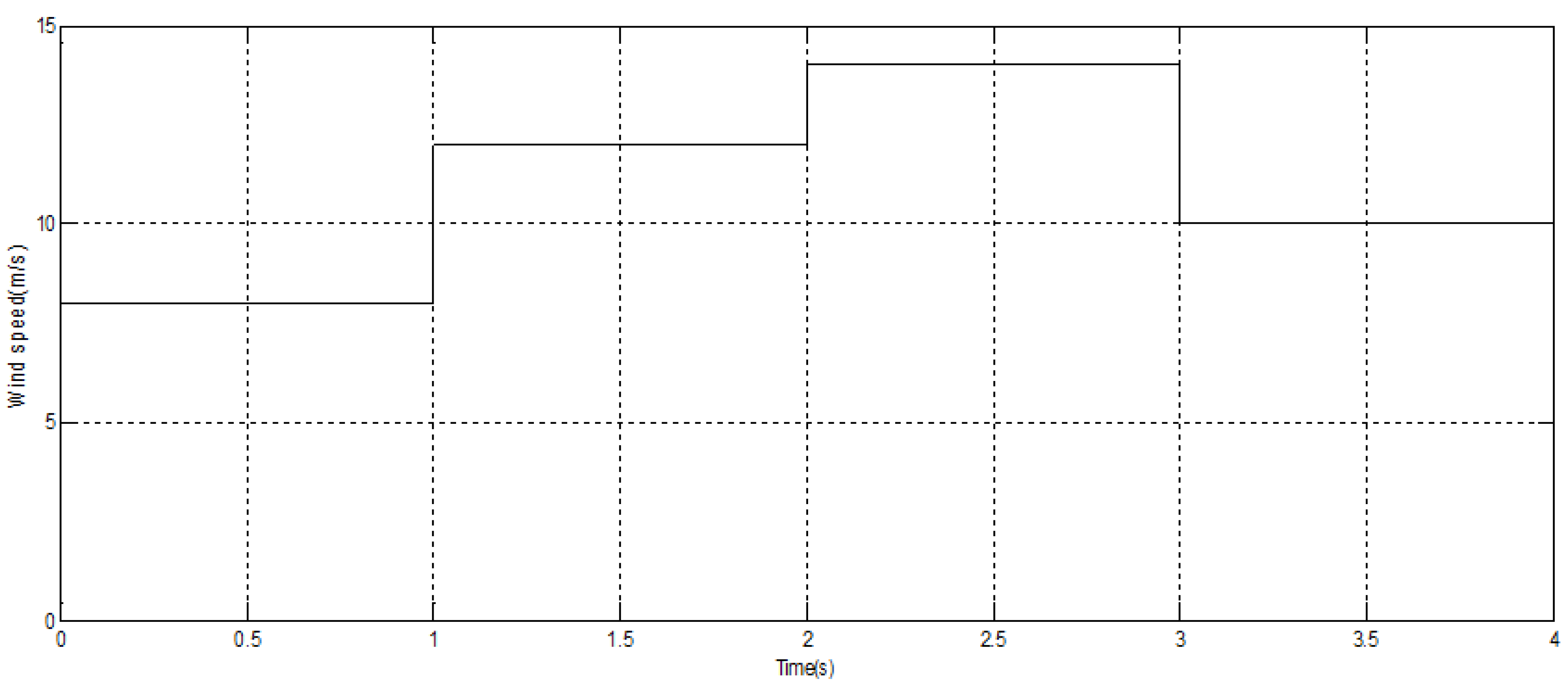
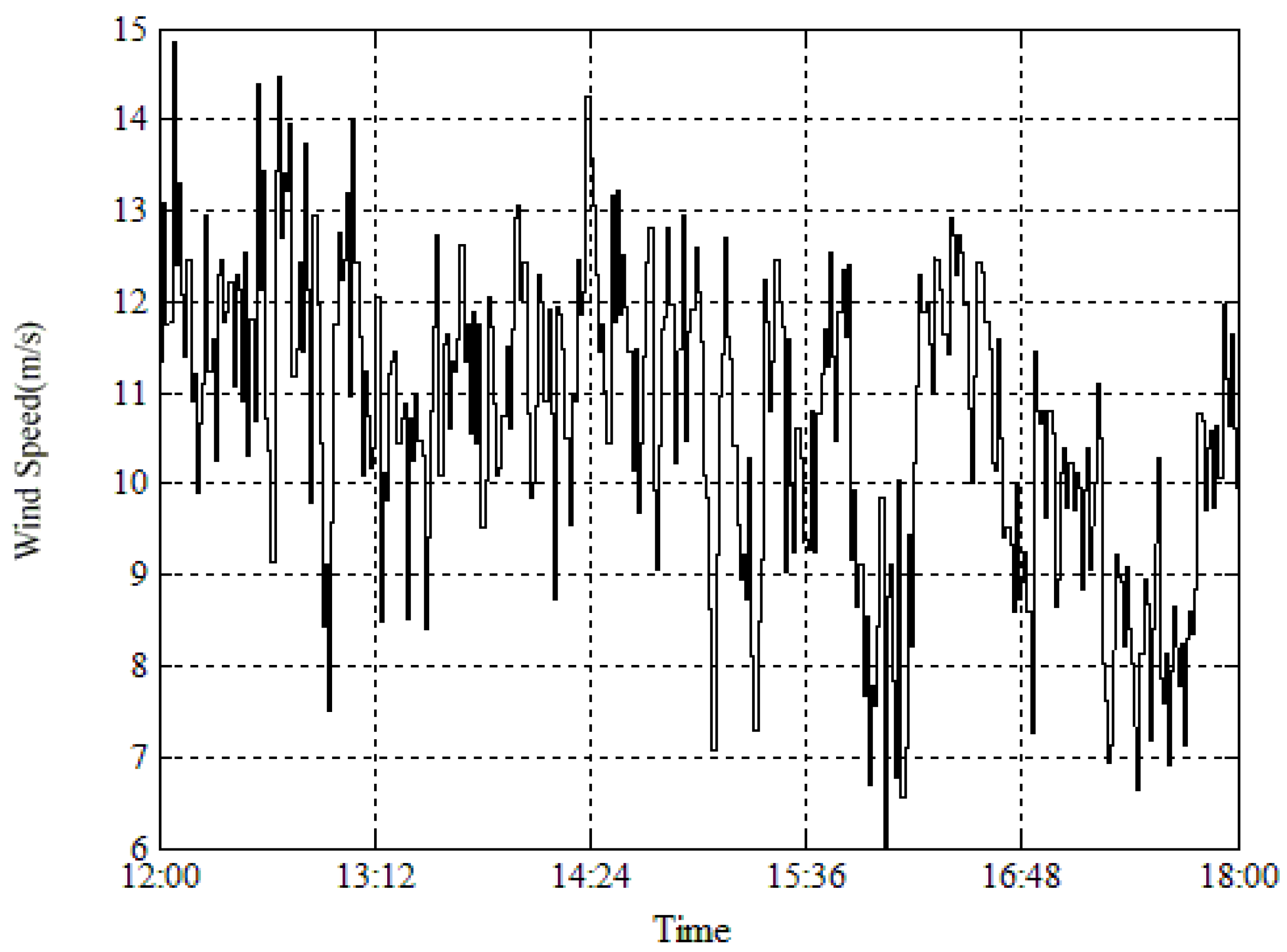
4.1. Simulation Model

Through the analysis of PWM converter control, in this paper the simulation model of the whole unit is built using Matlab/Simulink. The quantization factors and scale factors of the fuzzy controller are optimized by the improved PSO to guarantee the tracking of the optimized rotating speed and the stability of the DC voltage.
The simulation parameters of the wind turbines are: radius of wind turbine rotor, R = 38.7 m; rated wind speed, v = 12 m/s; air density, ρ = 1.225 kg/m3; the best tip-speed-ratio, λopt = 8; equivalent moment of inertia, J = 500 kg·m2; rated power is 2 MW; number of pole pairs of generator, Np = 40; inductance Ls = Lg = 2.56 mH; stator resistance, Rs = 0.01 Ω; grid side equivalent resistance, Rg = 80 Ω; flux of permanent magnet, ψf = 1.67 Wb; viscosity coefficient of transmission, B = 0.005 N/(m/s).
According to [49,51], we select a range that contains the corresponding parameter value of one parameter of the fuzzy controller. Then the initial value of the IPSO can be determined in that range. The length of the selected interval has little effect on the optimization results, but has an impact on the optimization time. Of course, in order to save time, a small interval may be selected. As a result, the improved PSO parameters of generator side converter are selected as: w = 0.8–1.2; c1 = 2.5–5.0; c2 = 0.5–2.5; N = 20; the number of particles is 10. The initial position of one particle is [ke(0), kec(0), kup(0), kui(0)], the components are random numbers between [0, 0.6], [0, 0.2], [5, 40] and [50, 300], respectively. The initial velocity of one particle is [ve(0), vec(0), vup(0), vui(0)], the components are of random numbers between [−0.02, 0.02], [−0.02, 0.02], [−4, 4] and [−30, 30], respectively.
Similarly, the improved PSO parameters of the grid side converter are selected as: w = 0.8–1.2; c1 = 2.5–5.0; c2 = 0.5–2.5; N = 30; the number of particles is 10. The components of the initial position of one particle are random numbers between [0, 0.25], [0, 0.01], [0, 10] and [0, 50], respectively. The components of the initial velocity of one particle are random numbers between [−0.025, 0.025], [−0.001, 0.001], [−1.000, 1.000], and [5.000, 5.000], respectively.

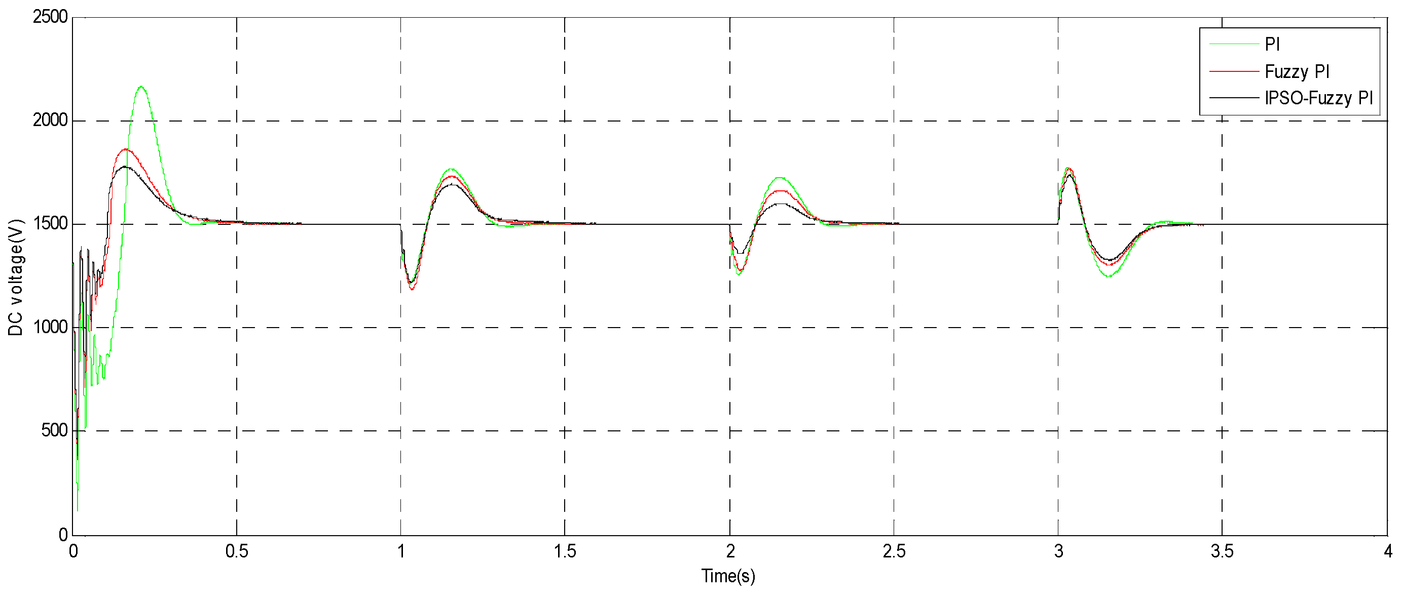
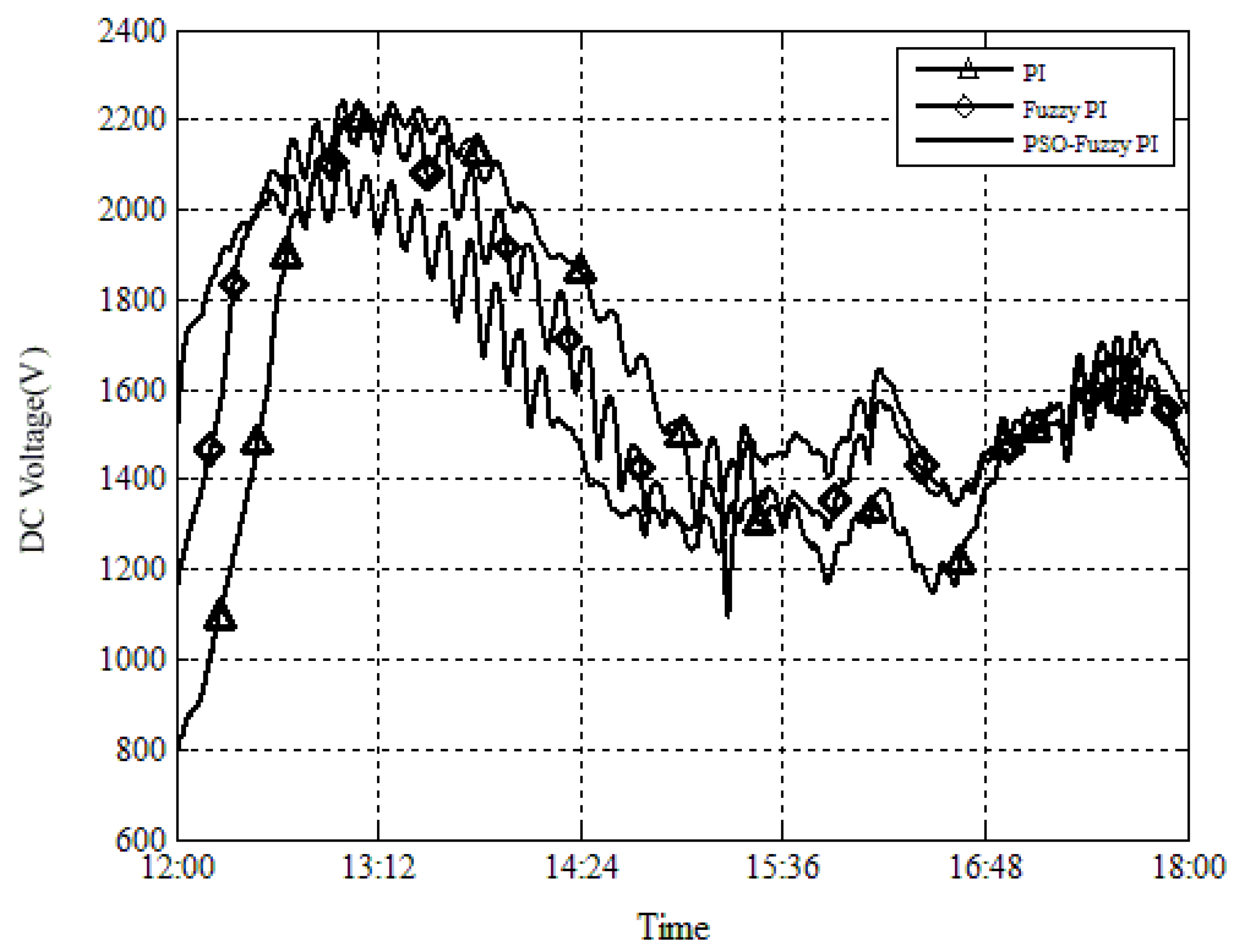
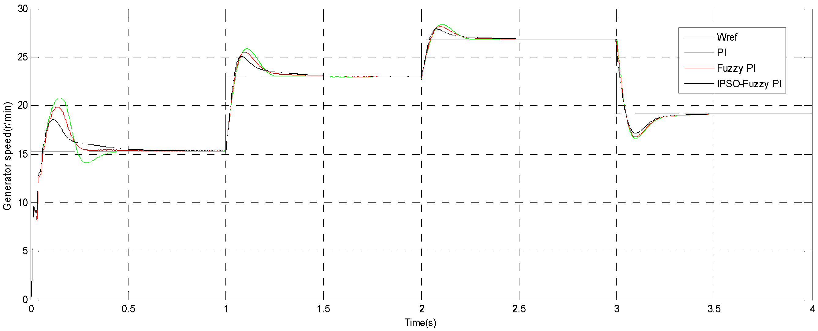
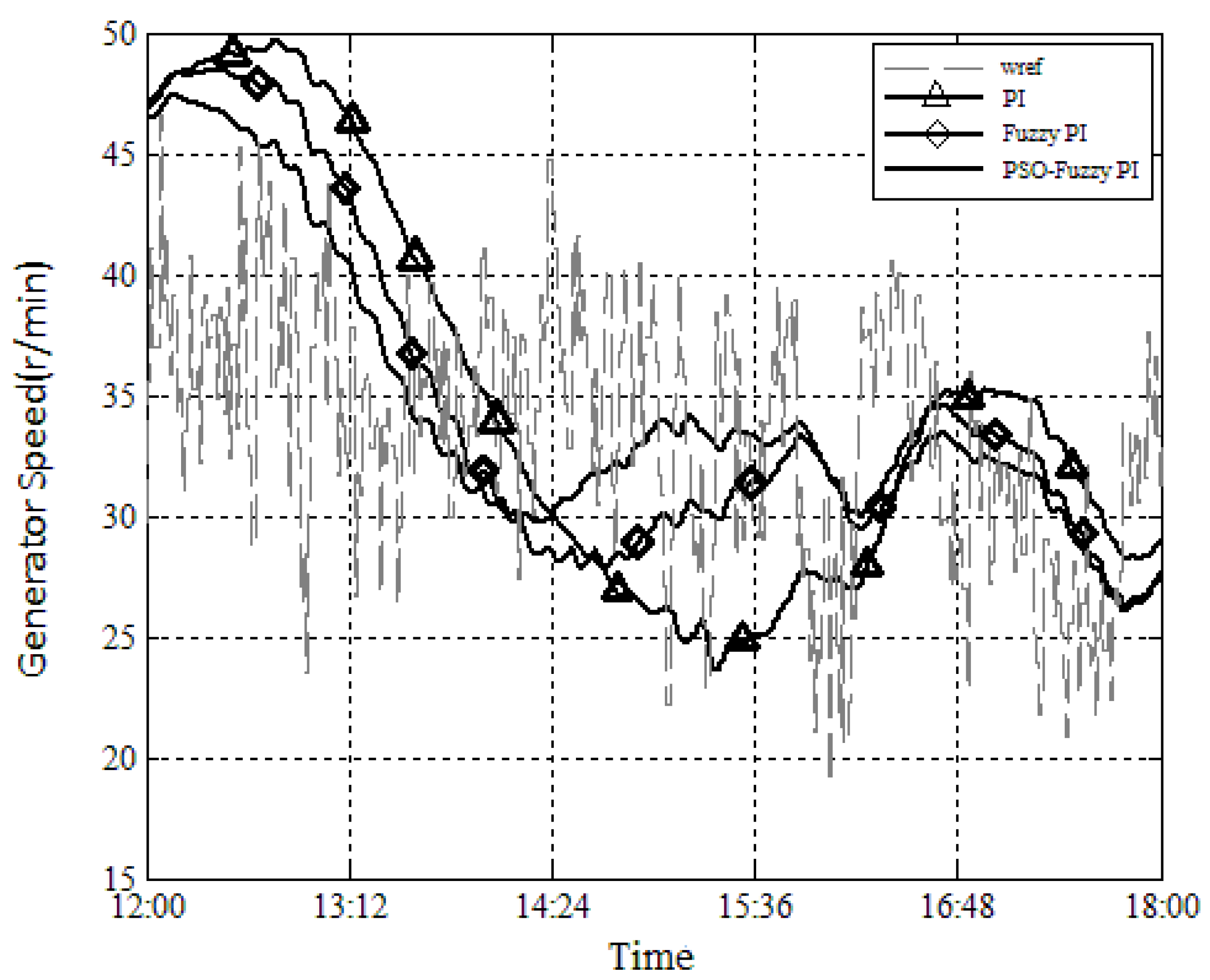
4.2. Analysis of Simulation Results

When the wind speed suddenly changes, a comparison of control effects among the IPSO-fuzzy PI controller, the conventional PI controller (kpd = kpq = 550, kid = kiq =5000, kpgd = kpgq = 10, kigd = kigq =100, these parameters are obtained by trial and error method) and the fuzzy PI controller (generator side: ke = 3/10, kec = 6/100, kup = 110/6, kui = 1000/6, grid side: ke = 6/500, kec = 6/2000, kup = 20/6, kui = 20/6 (these parameters are obtained by calculation and tests) can be made. An extreme case is used to demonstrate the response of the controller. The changing of wind speed is shown in Figure 6. The wind speed is 8 m/s before t = 1 s and increases suddenly to the rated speed 12 m/s at t = 1 s, then it remains till at t = 2 s, it increases suddenly to 14 m/s, and then it remains till at t = 3 s, then it decreases suddenly to 10 m/s.
Comparisons of generator speed change and DC voltage change among IPSO-fuzzy PI controller, fuzzy PI controller and conventional PI controller are shown in Figure 7 and Figure 8.
The overshoot and regulation time of the generator speed controlled by the three controllers are shown in Figure 7 and Table 2. It can be seen that the control for achieving the generator rated speed is realized by the generator side converter when the step change of wind velocity occurred. The overshoot and regulation time of the IPSO-fuzzy PI controller are less than that of the fuzzy PI controller and conventional PI controller. The overshoot given by the IPSO-fuzzy PI controller is reduced 3.3% compared with the fuzzy PI controller and 4.8% from the PI controller while the regulation time is reduced 41 ms from the fuzzy PI controller and 51 ms from the PI controller, respectively, when the wind speed changes suddenly from 8.0 m/s to 12.0 m/s. The overshoot given by the IPSO-fuzzy PI controller is reduced 1.8% by comparing with the fuzzy PI controller and 2.7% from the PI controller while the regulation time is reduced 45 ms from the fuzzy PI controller and 55 ms from the PI controller, respectively, when the wind speed changes suddenly from 12.0 m/s to 14.0 m/s. The overshoot given by the IPSO-fuzzy PI controller is reduced 4.3% compared with the fuzzy PI controller and 6.2% from the PI controller while the regulation time is reduced 39 ms from the fuzzy PI controller and 48 ms from the PI controller, respectively, when the wind speed changes suddenly from 14.0 m/s to 10.0 m/s.
The overshoot and regulation time of the DC voltage controlled by the three controllers are shown in Figure 8 and Table 3. The control effect of IPSO-fuzzy PI controller can be clearly observed to have less overshoot and faster regulation. The overshoot given by the IPSO-fuzzy PI controller is reduced to 12.6% from 15.3% and 17.7% compared with the fuzzy PI controller and the PI controller while the regulation time is reduced to 0.234 s from 0.239 s and 0.242 s from the fuzzy PI controller and the PI controller, respectively, when the wind speed changes suddenly from 8.0 m/s to 12.0 m/s. The overshoot given by the IPSO-Fuzzy PI controller is reduced to 6.5% from 10.9% and 15.1% in comparison with the fuzzy PI controller and the PI controller while the regulation time is reduced to 0.233 s from 0.236 s and 0.240 s from the fuzzy PI controller and the PI controller, respectively, when the wind speed changes suddenly from 12.0 m/s to 14.0 m/s. The overshoot given by the IPSO-fuzzy PI controller is reduced to 9.5% from 13.1% and 16.9% in comparison with the fuzzy PI controller and the PI controller while the regulation time is reduced to 0.241 s from 0.249 s and 0.258 s from the fuzzy PI controller and the PI controller, respectively, when the wind speed changes suddenly from 14.0 m/s to 10.0 m/s.
Figure 9 shows actual wind speed data collected in a wind farm. Comparisons of generator speed change and DC voltage change among the IPSO-fuzzy PI controller, fuzzy PI controller and conventional PI controller are shown in Figure 10 and Figure 11.
In Figure 10, the RMSE of the IPSO-fuzzy PI controller is 6.38 r/m, while the RMSEs of the fuzzy PI controller and the PI controller are 7.35 r/m and 8.56 r/m. In Figure 11, the RMSE of the IPSO-fuzzy PI controller is 239.01 V, while the RMSEs of the fuzzy PI controller and the PI controller are 304.61 V and 360.67 V. When RMSE is smaller, the output of the controller is closer to the ideal reference value. The obtained RMSEs also show the advantages of the IPSO-fuzzy PI controller.

5. Conclusions

In this paper, a new way of combining the PSO and fuzzy control is discussed. This strategy gives full play to the rapidity of improved PSO by global optimization of the four parameters of the fuzzy PI controller. The new method is used in the control of the generator side and grid side converter for a PMDD wind turbine. Compared with the PI controller and fuzzy PI controller, the proposed fuzzy PI controller based on IPSO not only meets the requirements under the situation when wind speed changes suddenly, but also ensures the fuzzy PI controller to have optimal parameters to achieve the optimum control, which makes the adjustment process faster.
Based on the simulation, the specific results have been observed and discussed in Section 4.2 in terms of overshoot and regulation time of generator speed and DC voltage for different ranges of wind speed change. It is evidenced that the IPSO-fuzzy PI controller can give better performance than a fuzzy PI controller or PI controller when there is a sudden change of wind speed in power production.
With the actual wind speed recorded from a wind farm in the simulation, the RMSE of the generator speed given by the IPSO-fuzzy PI controller is reduced to 6.38 r/m from 7.35 r/m and 8.56 r/m by comparing with the fuzzy PI controller and the PI controller while the RMSE of the DC voltage is reduced to 239.01 V from 304.61 V and 360.67 V from the fuzzy PI controller and the PI controller, respectively.
This paper focuses only on the new control strategy of a wind turbine converter for the MPPT stage when the wind speed is mainly below the rated level. There is potential to extend the study to other stages. Meanwhile, the actual operation of the system may drop in grid voltage or load imbalance, but the present paper only considers the normal situation. Moreover, the IPSO also needs time to run and it might require new hardware to be installed in practical implementation. As a result, when implementing the controller in reality in a microprocessor, the calculation speed of the microprocessor needs to be higher in order to complete the complex arithmetic operations during the wind speed sampling interval. In fact, however, the wind speed is usually sampled every minute in the current industry practice, completing the intelligent control algorithm in microprocessor in such a short time is difficult so that, in actual operation, enquiry tables should be generated offline according to different simulations and then the microprocessor can query the lookup table online. How much or how long after the wind speed change before using the IPSO needs to be tested and verified before the real application. Therefore, further research will be pursued on practical application of the developed fuzzy PI controller based on improved PSO.

Acknowledgments

This work was supported by the National Natural Science Foundation of China (51577008). The authors are grateful to the anonymous reviewers for their constructive comments on the previous version of the paper.

Author Contributions

Yancai Xiao and Tieling Zhang contributed to paper writing and the whole revision process. Yancai Xiao also conceived design of the simulation. Zeyu Ding and Chunya Li performed simulation and experiments, and generated report.

Conflicts of Interest

The authors declare no conflicts of interest.

References

  1. The US Department of Energy (US DoE). Chapter 4: The Wind Vision Roadmap: A Pathway Forward in Wind Vision: A New Era for Wind Power in the United States. Available online: http://www.energy.gov/sites/prod/files/wv_chapter4_the_wind_vision_roadmap.pdf (accessed on 20 March 2016).
  2. European Wind Energy Association. Pure Power: Wind energy targets for 2020 and 2030, 2009 update. Available online: http://www.ewea.org/fileadmin/ewea_documents/documents/publications/reports/Pure_power_Full_Report.pdf (accessed on 31 July 2015).
  3. China May Have 500 GW of Wind Parks in 2030–Study (21 Oct 2014). Available online: http://renewables.seenews.com/news/china-may-have-500-gw-of-wind-parks-in-2030-study-444069 (accessed on 20 March 2016).
  4. Goudarzi, N.; Zhu, W.D. A review on the development of wind turbine generators across the world. Int. J. Dyn. Control 2013, 1, 192–202. [Google Scholar] [CrossRef]
  5. Poliner, H.; Van Der Pijl, F.F.A.; De Vilder, G.J.; Tavner, P. Comparison of direct-drive and geared generator concepts for wind turbines. IEEE Trans. Energy Convers. 2006, 21, 725–733. [Google Scholar] [CrossRef]
  6. Liserre, M.; Cardenas, R.; Molinas, M.; Rodriguez, J. Overview of multi-MW wind turbine and wind parks. IEEE Trans. Ind. Electron. 2011, 58, 1081–1095. [Google Scholar] [CrossRef]
  7. Sheela, J.; Mary, A.; Sivasakthi, S. A novel integrated AC/DC/AC converter for direct drive permanent magnet wind power generation system. Int. J. Eng. Res. Technol. 2013, 2, 1–12. [Google Scholar]
  8. Minh, H.Q.; Cuong, N.C.; Chau, T.N. A fuzzy-logic based MPPT method for stand-alone wind turbine system. Am. J. Eng. Res. 2014, 3, 177–184. [Google Scholar]
  9. Bao, Y.; Wang, H.; Zhang, J. Adaptive inverse control of variable speed wind turbine. Nonlinear Dyn. 2010, 61, 819–827. [Google Scholar] [CrossRef]
  10. Nourdine, S.; Díaz De Corcuera, A.; Camblong, H.; Landaluze, J.; Vechiu, I.; Tapia, G. Control of wind turbines for frequency regulation and fatigue loads reduction. In Proceedings of the 6th Dubrovnik Conference on Sustainable Development of Energy, Water and Environment Systems, Dubrovnik, Croatia, 25–29 September 2011; pp. 25–29.
  11. Wright, A.D. Modern Control Design for Flexible Wind Turbines, NREL/TP-500–35816; Technical Report for NREL: Golden, CO, USA, 2004. [Google Scholar]
  12. Wright, A.D.; Fingersh, L.J.; Balas, M.J. Testing state-space controls for the controls advanced research turbine. J. Sol. Energy Eng. 2006, 128, 506–515. [Google Scholar] [CrossRef]
  13. Sanz, M.G.; Torres, M. Aerogenerador síncrono multipolar de velocidad variable y 1.5 MW de potencia: TWT1500. Available online: http://intranet.ceautomatica.es/old/actividades/jornadas/XXIV/documentos/incon/134.pdf (accessed on 26 March 2016).
  14. Bianchi, F.D.; Battista, H.D.; Mantz, R.J. Wind turbine control systems. In Principles, Modelling and Gain Scheduling Design; Springer-Verlag: London, UK, 2007. [Google Scholar]
  15. De Corcuera, A.D.; Pujana-Arrese, A.; Ezquerra, J.M.; Segurola, E.; Landaluze, J. H based control for load mitigation in wind turbines. Energies 2012, 5, 938–967. [Google Scholar] [CrossRef]
  16. Chen, T.X.; Dai, Q.; Tao, J. Wind power permanent magnet synchronous generator based on sliding mode variable structure cascade control. Electr. Autom. 2008, 30, 8–11. [Google Scholar]
  17. Boukhezzar, B.; Siguerdidjane, H. Nonlinear control of a variable-speed wind turbine using a two-mass model. IEEE Trans. Energy Convers. 2011, 26, 149–162. [Google Scholar] [CrossRef]
  18. Bououden, S.; Chadli, M.; Filali, S.; El Hajjaji, A. Fuzzy model based multivariable predictive control of a variable speed wind turbine: LMI approach. Renew. Energy 2012, 37, 434–439. [Google Scholar] [CrossRef]
  19. Sargolzaei, J.; Kianifar, A. Neuro-fuzzy modeling tools for estimation of torque in Savonius rotor wind turbine. Adv. Eng. Softw. 2010, 41, 619–626. [Google Scholar] [CrossRef]
  20. Sheikhan, M.; Shahnazi, R.; Yousefi, A.N. An optimal fuzzy PI controller to capture the maximum power for variable-speed wind turbines. Neural Comput. Appl. 2013, 23, 1359–1368. [Google Scholar] [CrossRef]
  21. Munteanu, L.; Bratcu, A.L.; Cutululis, N.A.; Ceanga, E. Optimal Control of Wind Energy Systems; Springer-Verlag: London, UK, 2008; pp. 109–168. [Google Scholar]
  22. Mullane, A.; Lightbody, G.; Yacamini, R. Adaptive control of variable speed wind turbines. Available online: http://www.cder.dz/download/upec-13.pdf (accessed on 26 March 2016).
  23. Giraldo, E.; Garces, A. An adaptive control strategy for a wind energy conversion system based on PWM-CSC and PMSG. IEEE Trans. Power Syst. 2014, 29, 1446–1453. [Google Scholar] [CrossRef]
  24. Shariff, R.; Zhang, Q.J.; Cudrak, A.; Stanley, S.J.; Smith, D.W.; Baxter, C.W. Real-Time Artificial Intelligence Control and Optimization of a Full-Scale WTP; Awwa Research Foundation: Denver, CO, USA, 2006; pp. 9–20. [Google Scholar]
  25. Amine, B.M.; Souhila, Z.; Tayeb, A.; Ahmed, M. Adaptive fuzzy logic control of wind turbine emulator. Int. J. Power Electron. Drive Syst. 2014, 4, 233–240. [Google Scholar]
  26. Vanitha, K.; Shravani, C. Permanent magnet synchronous generator with fuzzy logic controller for wind energy conversion system. Int. J. Eng. Res. Technol. 2013, 2, 3943–3950. [Google Scholar]
  27. Minh, H.Q.; Frédéric, N.; Najib, E.; Abdelaziz, H. Control of permanent magnet synchronous generator wind turbine for stand-alone system using fuzzy logic. In Proceedings of the 7th Conference of the European Society for Fuzzy Logic and Technology, Aix-les-Bains, France, 18–22 July 2011; pp. 720–727.
  28. Yin, X.X.; Lin, Y.G.; Li, W.; Gu, Y.J.; Lei, P.F.; Liu, H.W. Sliding mode voltage control strategy for capturing maximum wind energy based on fuzzy logic control. Int. J. Emerg. Electr. Power Syst. 2015, 70, 45–51. [Google Scholar] [CrossRef]
  29. Pratap, A.; Howlader, A.M.; Senjyu, T.; Yona, A.; Urasaki, N.; Funabashi, T. Different strategies for controlling output power smoothing of a PMDG-based wind energy conversion systems. Int. J. Emerg. Electr. Power Syst. 2012, 13. [Google Scholar] [CrossRef]
  30. Melício, R.; Mendes, V.M.F.; Catalão, J.P.S. Fractional-order control and simulation of wind energy systems with PMSG/full-power converter topology. Energy Convers. Manag. 2010, 51, 1250–1258. [Google Scholar] [CrossRef]
  31. Beltran, B.; Ahmed-Ali, T.; Benbouzid, M.E.H. Sliding mode power control of variable-speed wind energy conversion systems. IEEE Trans. Energy Convers. 2008, 23, 551–558. [Google Scholar] [CrossRef] [Green Version]
  32. Li, S.H.; Haskew, T.A.; Xu, L. Conventional and novel control designs for direct driven PMSG wind turbines. Electr. Power Syst. Res. 2010, 80, 328–338. [Google Scholar] [CrossRef]
  33. Babu, N.R.; Arulmozhivarman, P. Wind energy conversion systems–A technical review. J. Eng. Sci. Technol. 2013, 8, 493–507. [Google Scholar]
  34. Kim, J.Y.; Kim, H.M.; Kim, S.K.; Jeon, J.H.; Choi, H.K. Designing an energy storage system fuzzy PID controller for microgrid islanded operation. Energies 2011, 4, 1443–1460. [Google Scholar] [CrossRef]
  35. Dorf, R.C.; Bishop, R. Modern Control System, 11th ed.; Prentice Hall: Upper Saddle River, NJ, USA, 2007. [Google Scholar]
  36. Kortabarria, I.; Andreu, J.; De Alegri’a, I.M.; Jime’nez, J.; Gárate, J.I.; Robles, E. A novel adaptive maximum power point tracking algorithm for small wind turbines. Renew. Energy 2014, 63, 785–796. [Google Scholar] [CrossRef]
  37. Venkataramana, N.N.; Singh, S.P. Improved torque and flux performance of type-2 fuzzy-based direct torque control induction motor using space vector pulse-width modulation. Electr. Power Compon. Syst. 2014, 42, 658–669. [Google Scholar] [CrossRef]
  38. Kim, H.W.; Kin, S.S.; Ko, H.S. Modeling and control of PMSG-based variable-speed wind turbine. Electr. Power Syst. Res. 2010, 80, 46–52. [Google Scholar] [CrossRef]
  39. Wu, R.; Dewan, S.B.; Slemon, G.R. Analysis of an AC to DC voltage source converter using PWM with phase and amplitude control. IEEE Trans. Ind. Appl. 1991, 27, 355–364. [Google Scholar] [CrossRef]
  40. Gopala, K.A.; Reddy, B.A.; Bhavani, P.D. Fuzzy PI and integrating type fuzzy PID controllers of linear, nonlinear and time-delay systems. Int. J. Comput. Appl. 2010, 1, 41–47. [Google Scholar]
  41. Tarique, A.; Gabbar, H.A. Particle swarm optimization (PSO) based turbine control. Intell. Control Autom. 2013, 4, 126–137. [Google Scholar] [CrossRef]
  42. Bhattacharyya, B.; Raj, S. PSO based bio inspired algorithms for reactive power planning. Int. J. Electr. Power Energy Syst. 2016, 74, 396–402. [Google Scholar] [CrossRef]
  43. Sahu, R.K.; Panda, S.; Sekhar, G.T.C. A novel hybrid PSO-PS optimized fuzzy PI controller for AGC in multi area interconnected power systems. Int. J. Electr. Power Energy Syst. 2015, 64, 880–893. [Google Scholar] [CrossRef]
  44. Tayal, V.K.; Lather, J.S. Reduced order H TCSC controller & PSO optimized fuzzy PSS design in mitigating small signal oscillations in a wide range. Int. J. Electr. Power Energy Syst. 2015, 68, 123–131. [Google Scholar]
  45. Esfahani, M.T.; Hosseinian, S.H.; Vahidi, B. A new optimal approach for improvement of active power filter using FPSO for enhancement power quality. Int. J. Electr. Power Energy Syst. 2015, 69, 188–199. [Google Scholar] [CrossRef]
  46. Khadanga, R.K.; Satapathy, J.K. Time delay approach for PSS and SSSC based coordinated controller design using gybrid PSO-GSA algorithm. Int. J. Electr. Power Energy Syst. 2015, 71, 262–273. [Google Scholar] [CrossRef]
  47. Samuel, G.G.; Rajan, C.C.A. Hybrid: Particle Swarm Optimization—Genetic Algorithm and Particle Swarm Optimization—Shuffled Frog Leaping Algorithm for long-term generator maintenance scheduling. Int. J. Electr. Power Energy Syst. 2015, 65, 432–442. [Google Scholar] [CrossRef]
  48. Kongnam, C.; Nuchprayoon, S. A particle swarm optimization for wind energy control problem. Renew. Energy 2010, 35, 2431–2438. [Google Scholar] [CrossRef]
  49. Li, Y.G.; Gui, W.H.; Yang, H.H.; Li, J. Improved PSO algorithm and its application. J. Cent. South Univ. Technol. 2005, 12, 222–226. [Google Scholar] [CrossRef]
  50. Langdon, W.B.; Poli, R. Evolving problems to learn about particle swarm optimizers and other search algorithm. Evol. Comput. 2007, 11, 561–578. [Google Scholar] [CrossRef]
  51. Ratnaweera, A.; Halgamuge, S. Self-organizing hierarchical particle swarm optimizer with time-varying acceleration coefficients. Evol. Comput. 2004, 8, 240–255. [Google Scholar] [CrossRef]
Figure 1. Permanent magnet direct drive (PMDD) wind turbine system.
Energies 09 00343 g001
Figure 2. Control schematic of the generator side converter.
Energies 09 00343 g002
Figure 3. Control schematic of the grid side converter.
Energies 09 00343 g003
Figure 4. Structure of fuzzy PI controller.
Energies 09 00343 g004
Figure 5. Structure of the fuzzy PI controller based on improved particle swarm optimization (PSO).
Energies 09 00343 g005
Figure 6. Changing of wind speed.
Energies 09 00343 g006
Figure 7. Changing of generator speed.
Energies 09 00343 g007
Figure 8. Changing of DC voltage.
Energies 09 00343 g008
Figure 9. The actual wind speed.
Energies 09 00343 g009
Figure 10. Generator speed changing at actual wind speed.
Energies 09 00343 g010
Figure 11. DC voltage changing at actual wind speed.
Energies 09 00343 g011
Table 1. Comparison of various control techniques applied to wind turbines.
Control techniquesAdvantageDisadvantage
  Fuzzy logic [21]  Maximizing the harvested power from the wind; improved dynamic response; fuzzy controller is more flexible.  Context dependence on the wind site features, wind turbine types, etc.; requiring quite consistent a priori knowledge; may not guarantee an optimal response [22].
  Adaptive  Does not need a priori information about the bounds on those uncertain or time-varying parameters of a dynamic system, mainly for pitch control, turbine and generator shaft torque control.  Require an adequate initialization of the controller parameters and detailed system data [23].
  Linear quadratic  Linear quadratic performance indicator is regarded as the objective function to determine the relationship between variables.  The resulting control is not optimal, but it is feasible and effective.
  Quantitative feedback theory (QFT) [21]  For robust control; effective for nonlinear systems with parameter uncertainty using both linearized and nonlinear model.  Based on the frequency-domain analysis; requires a lot of computational and graphical analysis.
  Linear parameter varying (LPV)  Nonlinear dynamic system, only the parameters are variable, commonly used measure performance based on norm, stable and robust control.  Complex modeling; a large amount of calculation; complex control strategies.
  H  Good robust control; the design idea is clear, especially for multi-input multi-output system to use.  Theory complexity; large calculation cost and limited parameter change scope.
  Sliding mode variable structure cascade control  Fast response, simple, robust.  Prone to buffeting.
  State feedback control   Fully reflect the characteristics of the internal system; effectively improve the system performance.  State variables often cannot be measured directly from outside of the system; as a result, its implementation is often more complex.
  Predictive control  Convenience for modeling, not require in-depth understanding of the internal mechanism of the process; robust control.  Stability constraints may affect the achievement of the control performance and it will also affect the real-time algorithm. For nonlinear systems, state trajectory generation tends to be more difficult.
  Artificial neural network (ANN)-based control  With parallel processing and self-learning ability.  Requires a lot of training samples to train the network; preparation of datasets for ANN training is largely user- dependent; ANN models do not yield explicit mathematical formulae [24].
Table 2. Overshoot and regulation times of the generator speed.
Wind speed (m/s)Overshoot (%)Regulating time (s)
PIFuzzy PIIPSO-Fuzzy PIPIFuzzy PIIPSO-Fuzzy PI
836.229.518.40.3990.2330.203
1212.5117.70.1830.1730.132
146.75.84.00.1790.1690.124
1012.310.46.10.1820.1730.134
Table 3. Overshoot and regulation times of the DC voltage.
Wind speed (m/s)Overshoot (%)Regulating time (s)
PIFuzzy PIIPSO-Fuzzy PIPIFuzzy PIIPSO-fuzzy PI
844.424.118.50.3120.3080.3
1217.715.312.60.2420.2390.234
1415.110.96.50.2400.2360.233
1016.913.19.50.2580.2490.241

