
Short-Circuit Calculation in Distribution Networks with Distributed Induction Generators


Abstract
:1. Introduction
2. Sequence Component Current Model of Induction Generators (IGs)
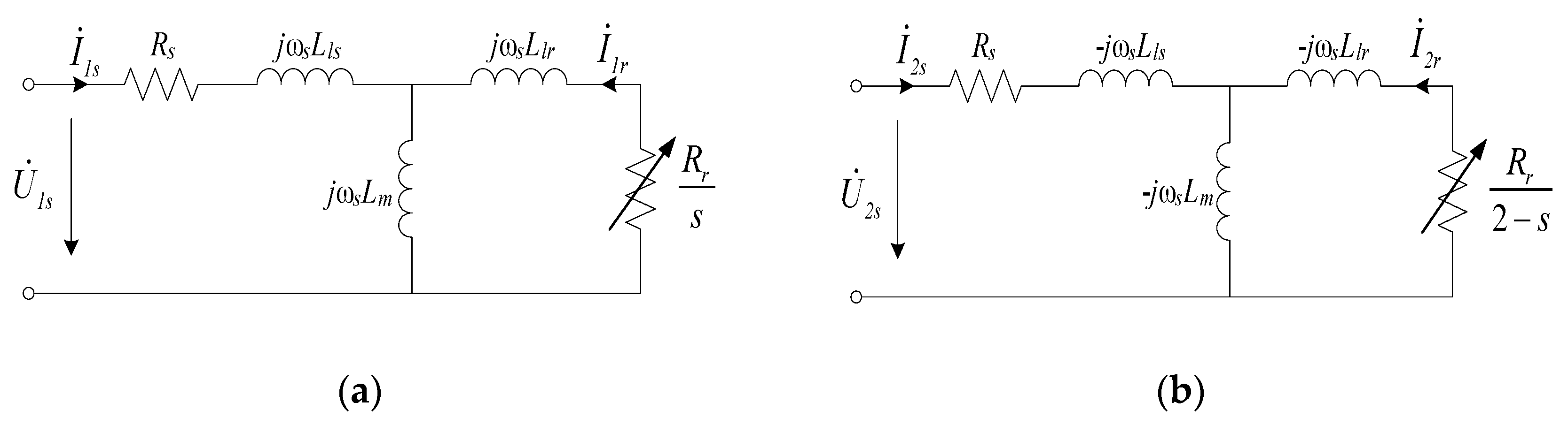
2.1. Stator and Rotor Flux of IGs during Grid Faults
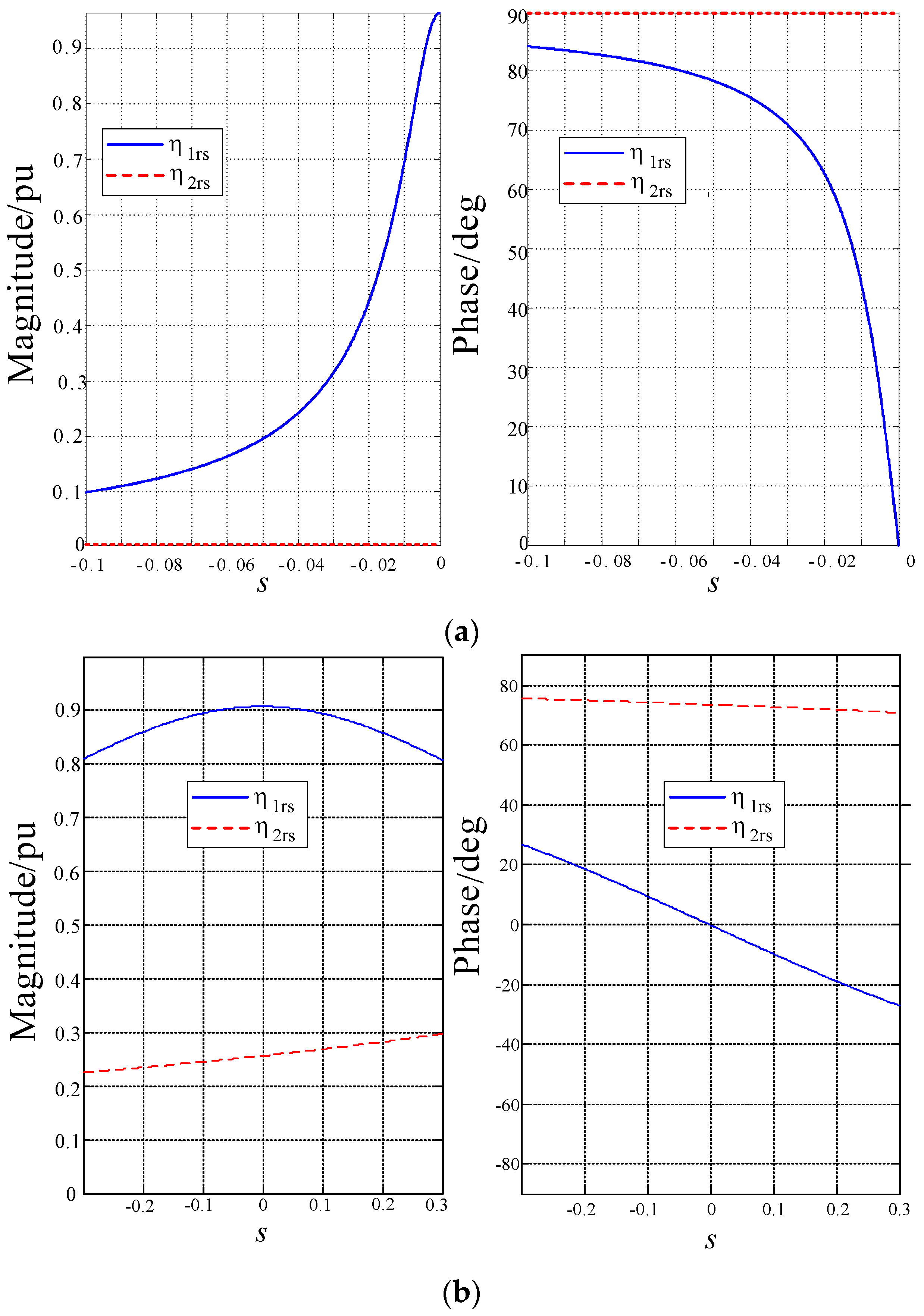
2.2. Sequence Component Current Model of Fixed-Speed IGs
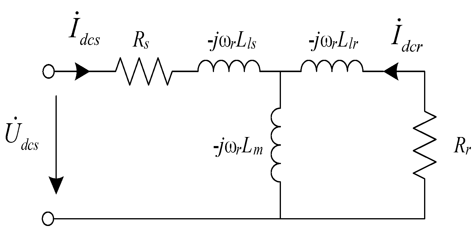
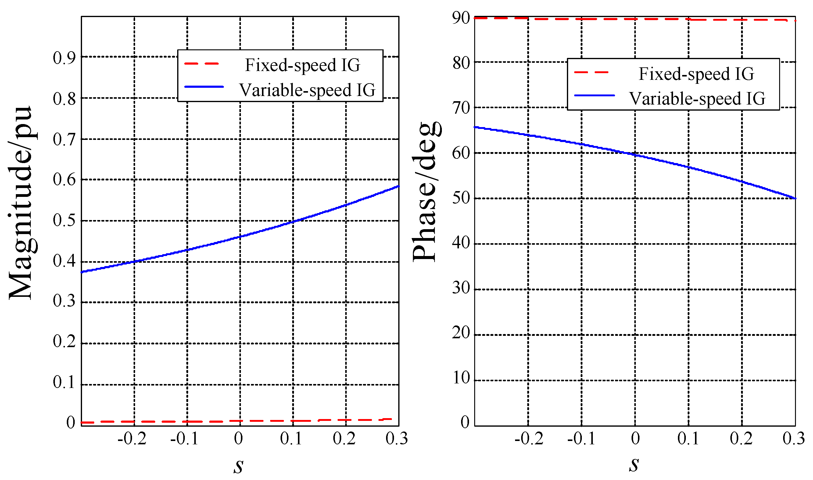
2.3. Sequence Component Current Model of Variable-Speed IGs
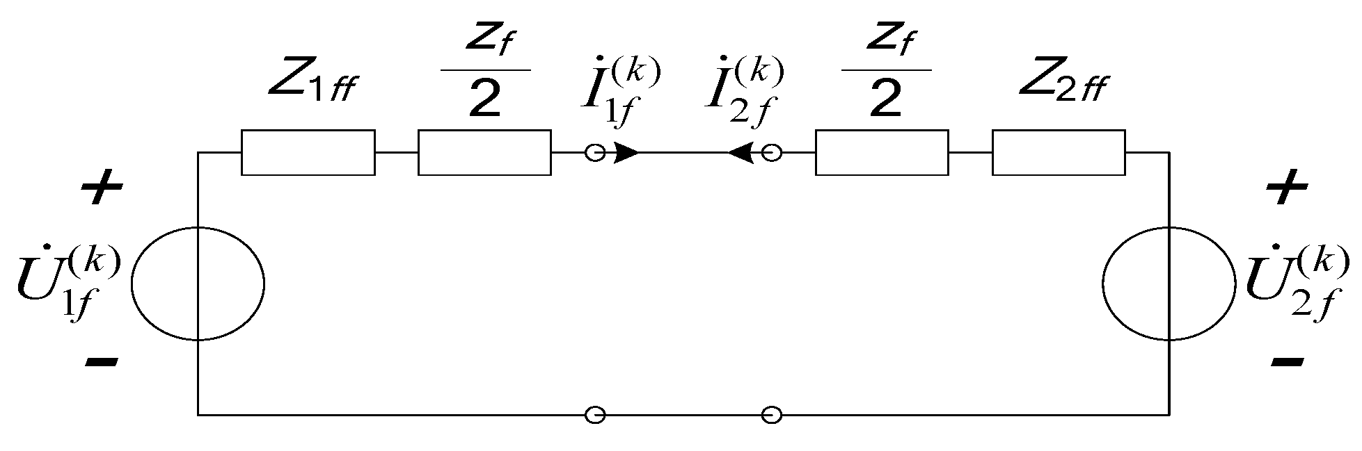
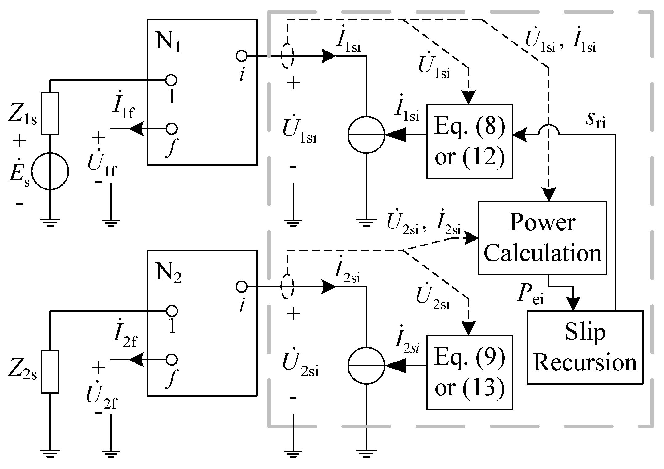
3. Coupling Relationship between Short-Circuit Current of IGs and the Distribution Network
4. Short-Circuit Calculation of the Multi-IG Network
4.1. Initial Value Calculation for Short-Circuit CurrentSequence Components of IGs
4.2. Short-Circuit CurrentSequence Components of IGs during Grid Faults
4.3. Procedure of Short-Circuit Calculation
- Step 1: Form the original matrixes Z1 and Z2 of the pre-fault network without IGs, determine the pre-fault voltage and stator current of each IG according to the mechanical torque during normal operation, and solve Equation (16) to obtain .
- Step 2: Add and to Z1 and Z2 to form the matrixes Z1′ and Z2′, obtain by Equation (17) and , and then determine and according to the fault node and type.
- Step 3: Solve Equation (19) to obtain and , determine and , and solve Equation (20) to obtain and .
- Step 4: Solve Equation (8) for a fixed-speed IG, Equation (12) for a variable-speed IG with and si(1) to obtain , determine the RMS of the positive and negative sequence components and , set = , = , = and = , and then go to Step 5.
- Step 5: Solve Equation (24) by calculating of using Equation (23) to obtain the slip vector s(k).
- Step 6: Solve Equation (25) with Z1 and Z2 to obtain the voltage and of the normal network, calculate and , substitute them into Equation (27) to obtain and of the fault component network, and determine the voltages and of each IG.
- Step 7: Solve Equations (8) and (9) for a fixed-speed IG, Equations (12) and (13) for a variable-speed IG with , s(k) and to obtain and , substitute = and into (22) to obtain , and = .
- Step 8: If k ≤ N (N = 20), set k = k + 1 and go to Step 5; otherwise, stop the iteration and output the RMS of sequence components of the short-circuit current of each IG.
5. Simulation Studies
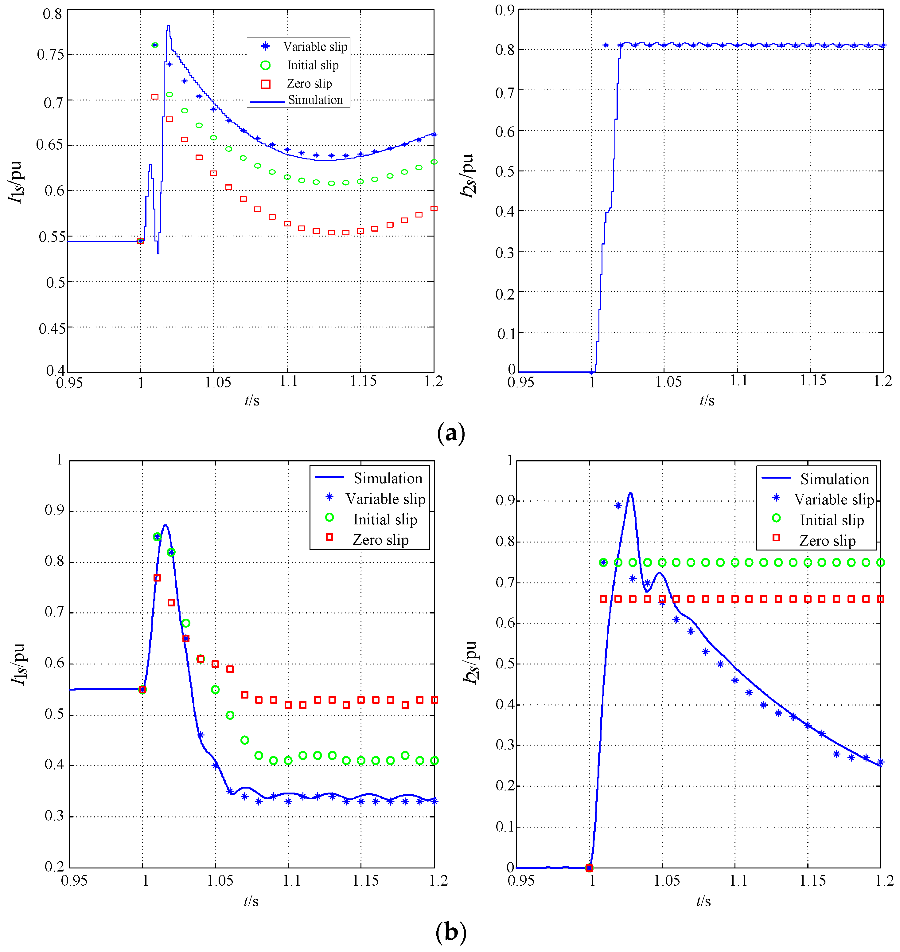
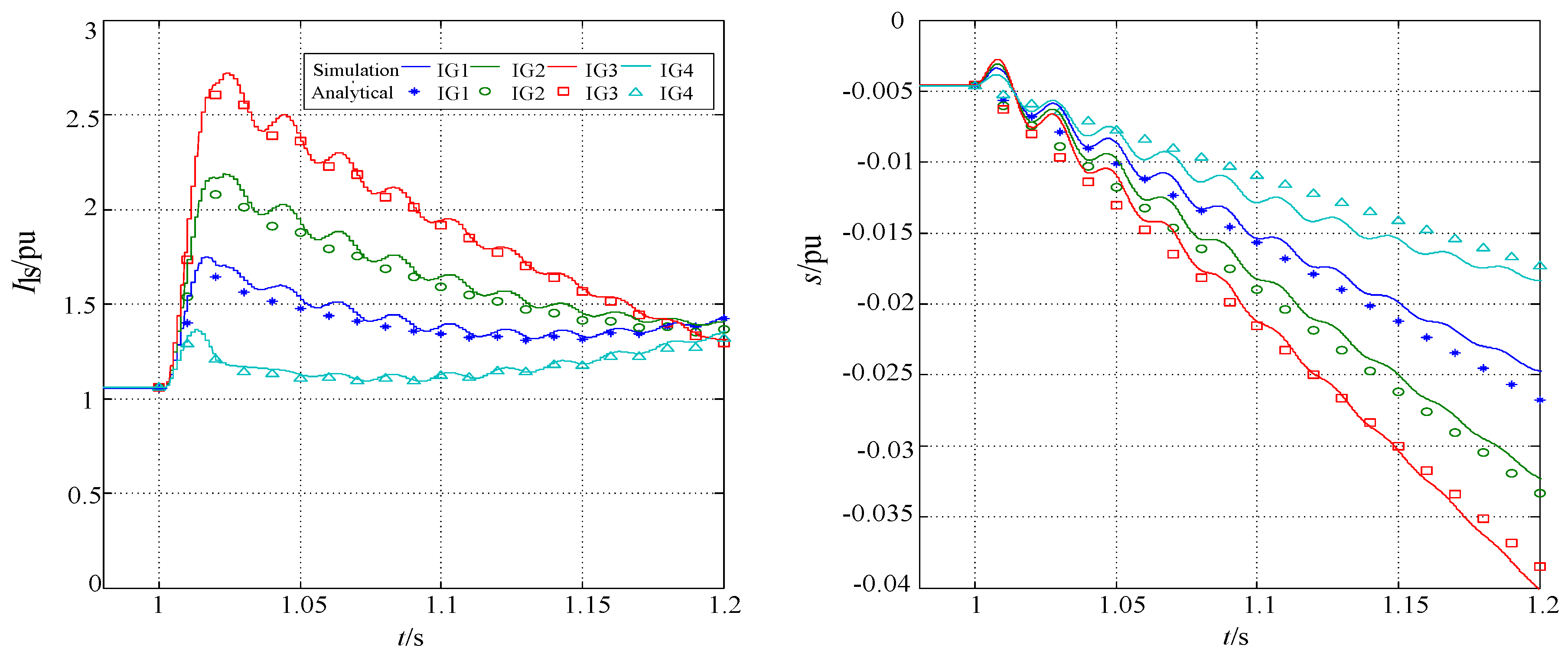
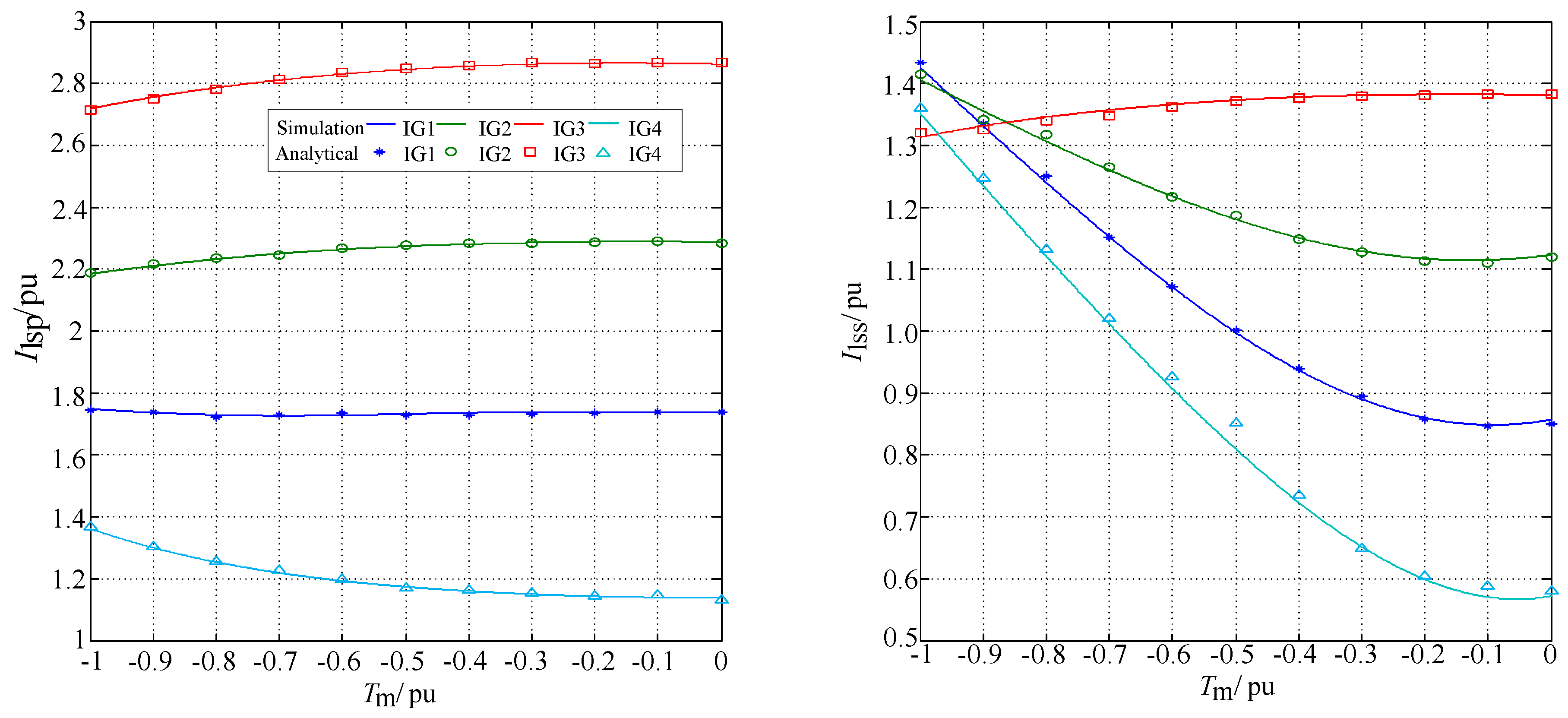
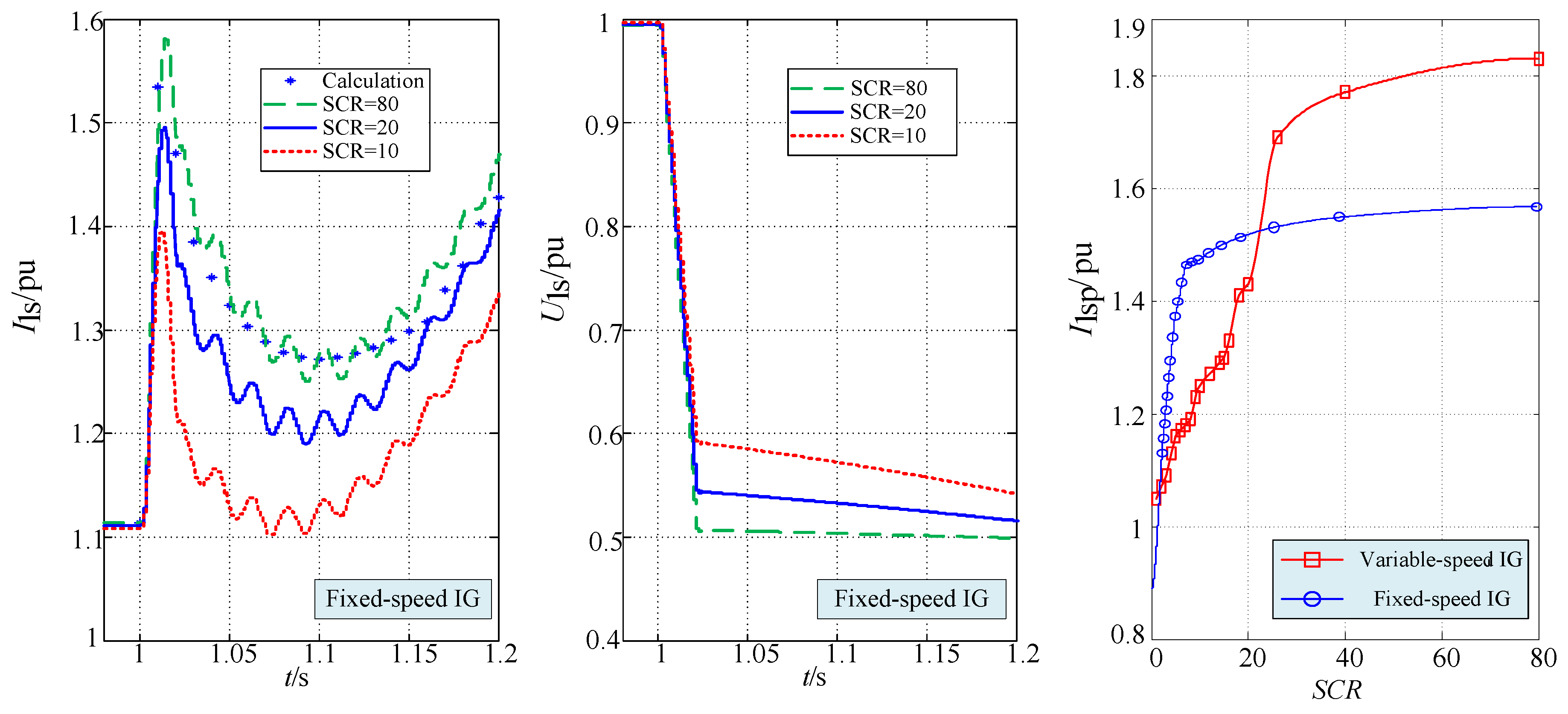
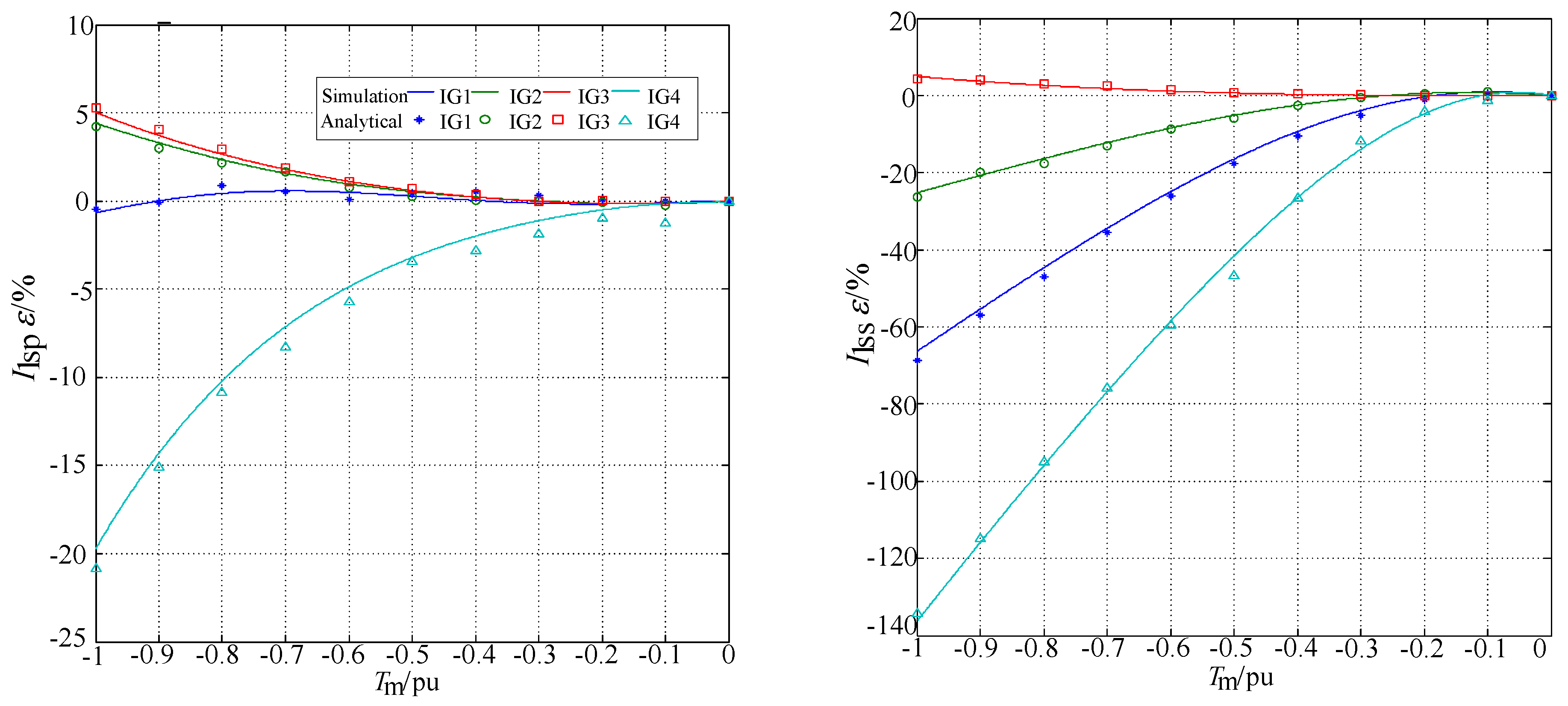
5.1. Three-Phase Short Circuit of Fixed-Speed IGs
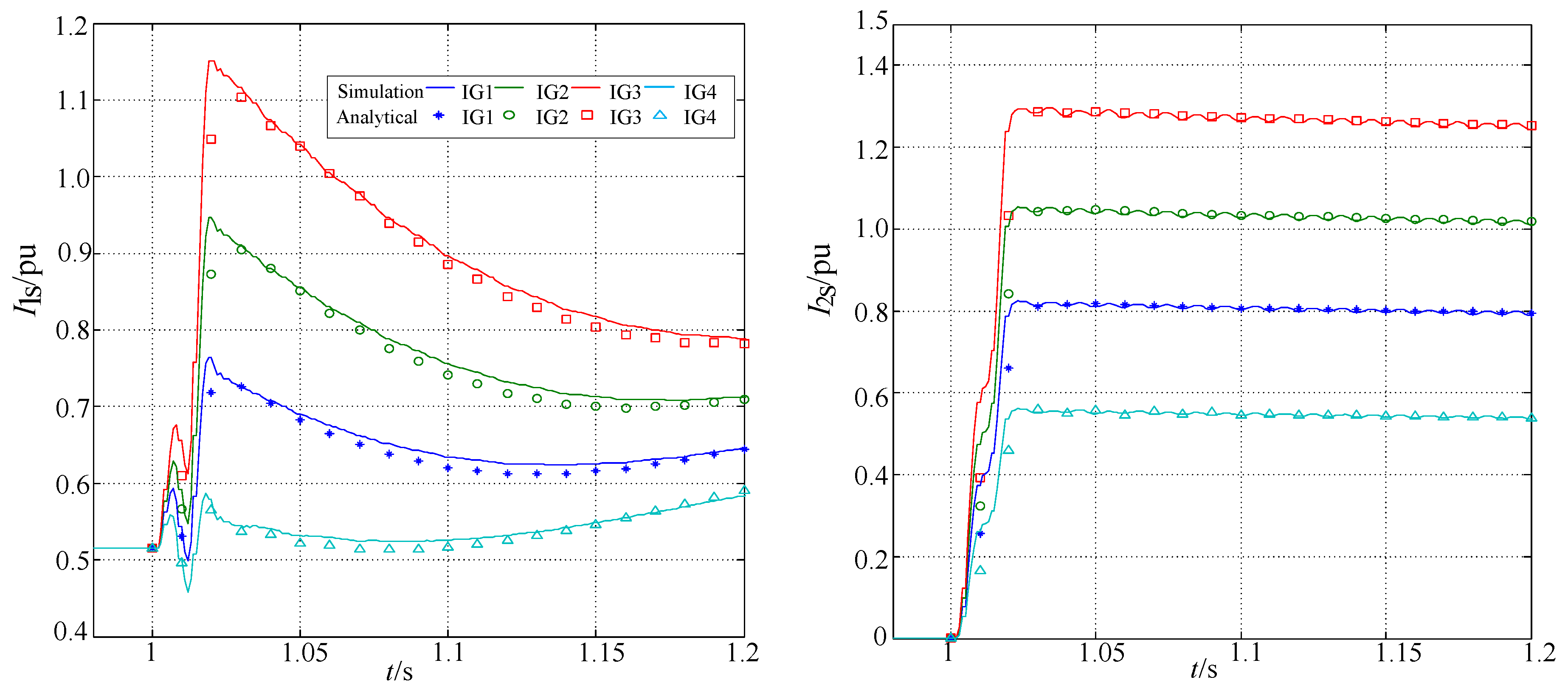
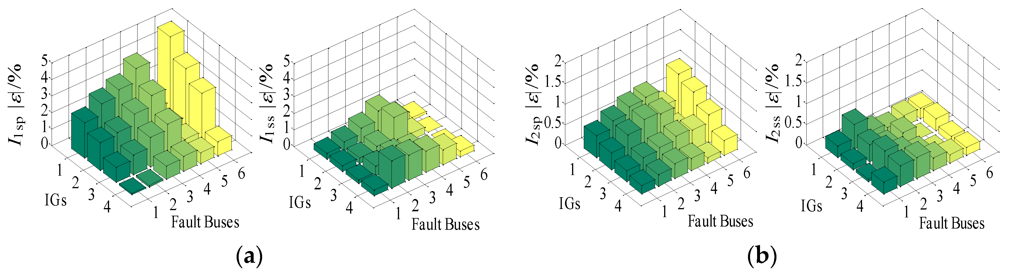
5.2. Two-Phase Short Circuit of Fixed-Speed IGs
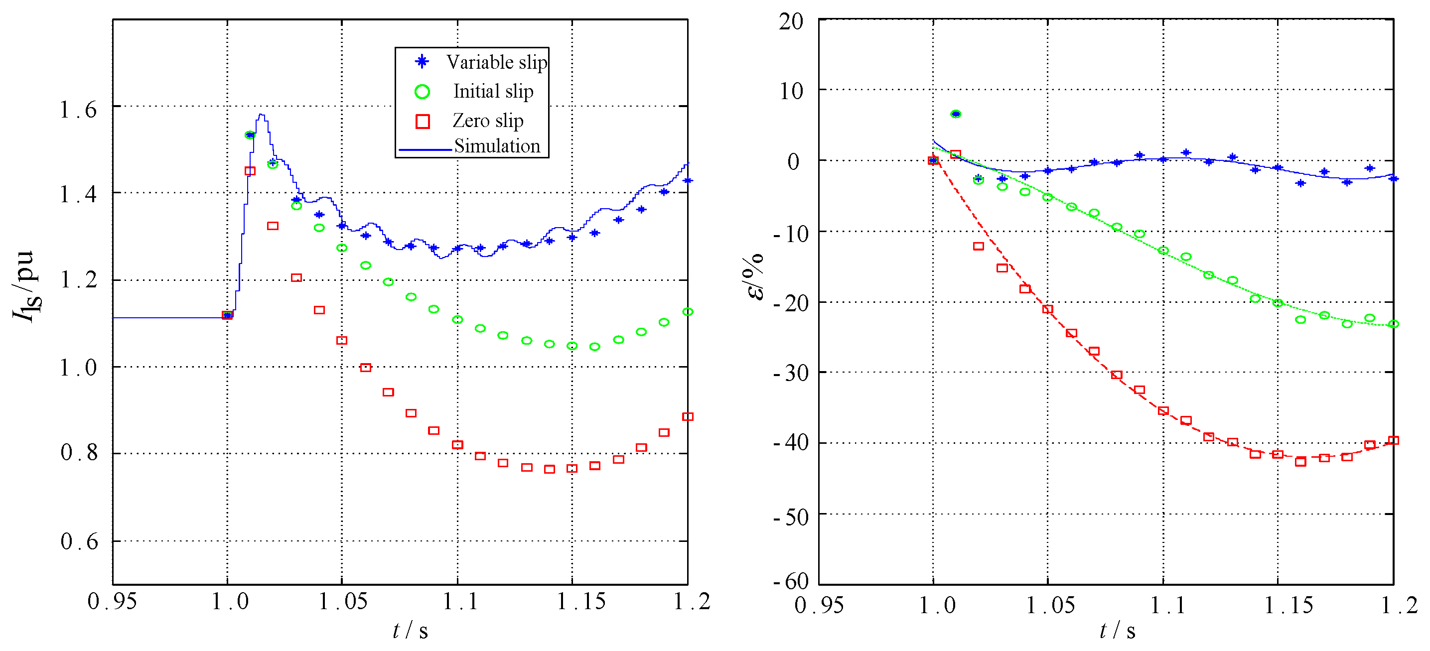
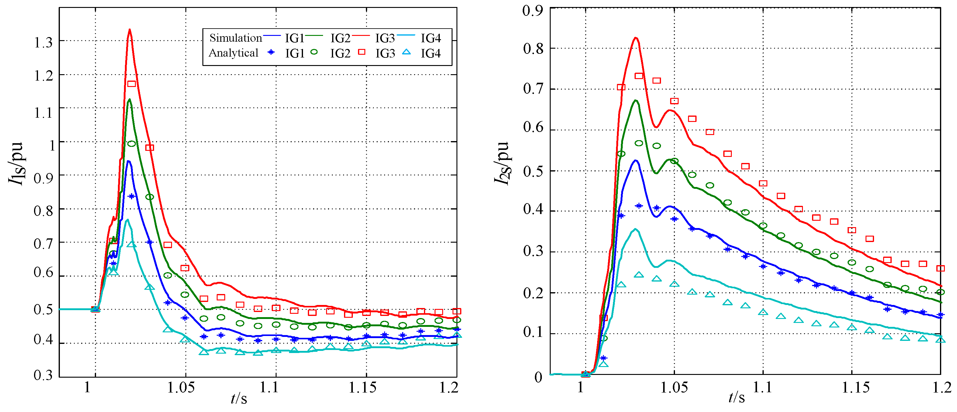
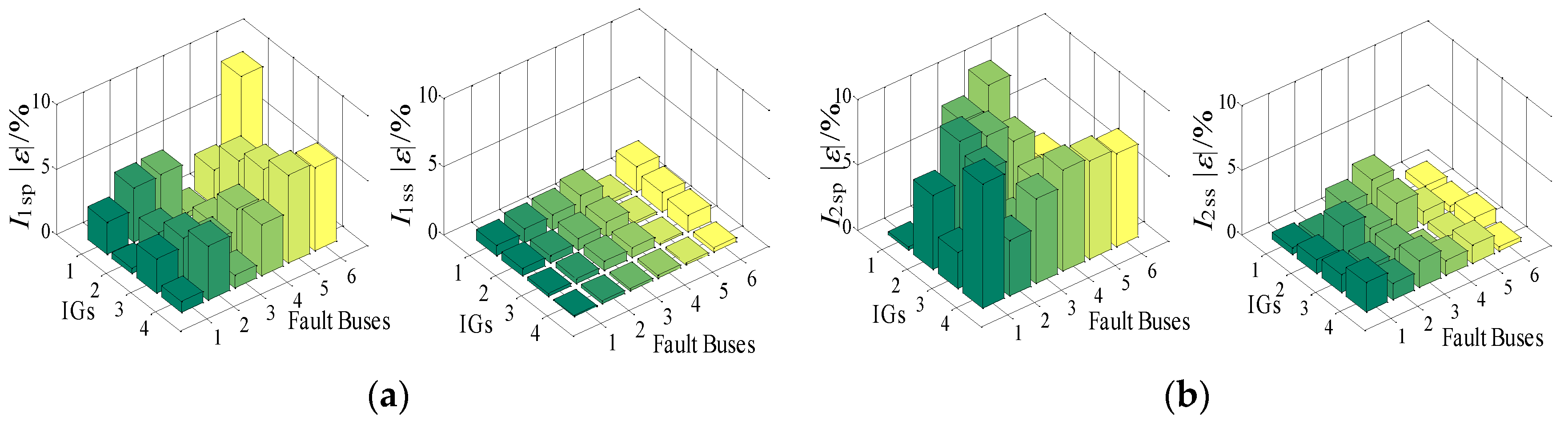
5.3. Two-Phase Short Circuit of Variable-Speed IGs
6. Conclusions
Acknowledgments
Author Contributions
Conflicts of Interest
Appendix A
Appendix B
- (1)
- The IG parameters:
- (a)
- Rated power = 3 MW, Rated AC voltage = 0.69 kV;
- (b)
- Rs = 0.004843 p.u., Xls = 0.1248 p.u.;
- (c)
- Rr = 0.004347 p.u., Xlr = 0.1791 p.u.;
- (d)
- Xm = 6.77 p.u., H = 5.04 s;
- (e)
- Capacitor rated voltage = 0.69 kV, Rated power = 0.75 Mvar for a fixed-speed IG;
- (f)
- Rated DC voltage = 1.5 kV, Crowbarresistance = 0.1043 p.u. for a variable-speed IG.
- (2)
- Transformer T1, T2, T3 and T4 have the same parameters:
- (a)
- Rated capacity = 3.5 MVA;
- (b)
- VI/VII (Yn/Δ) = 0.69/10.5 kV;
- (c)
- XT = 0.06 p.u., RT = 0.02 p.u..
- (3)
- The length of lines and impedance of per km are:
- (a)
- L1 = L2 = L3 = L4 = 0.5 km, L5 = 3.5 km;
- (b)
- ZL = j0.300 Ω/km.
- (4)
- The parameters of substation:
- (a)
- Rated Voltage = 10 kV, Es = 1.05 p.u.;
- (b)
- Short circuit level = 240 MVA, X/R = 10.
References
- Nimpitiwan, N.; Heydt, G.T.; Ayyanar, R.; Suryanarayana, S. Fault current contribution from synchronousmachine and inverter based distributed generators. IEEE Trans. Power Deliv. 2007, 22, 634–641. [Google Scholar] [CrossRef]
- Akhmatov, V. Induction Generators for Wind Power; Multi Science: Essex, UK, 2007. [Google Scholar]
- Freitas, W.; Vieira, J.C.M.; Morelato, A.; da Silva, L.C.P.; da Costa, V.F.; Lemos, F.A.B. Comparative analysis between synchronous and induction machines for distributed generation applications. IEEE Trans. Power Syst. 2006, 21, 301–311. [Google Scholar] [CrossRef]
- Huening, W.C. Calculating short-circuit currents with contributions from induction motors. IEEE Trans. Ind. Appl. 1982, IA-18, 85–92. [Google Scholar] [CrossRef]
- Morren, J.; de Haan, S.W.H. Short-circuit current of wind turbines with doubly fed induction generator. IEEE Trans. Energy Convers. 1991, 22, 174–180. [Google Scholar] [CrossRef]
- Boutsika, T.N.; Papathanassiou, S.A. Short-circuit calculations in networks with distributed generation. Electr. Power Syst. Res. 2008, 78, 1181–1191. [Google Scholar] [CrossRef]
- Sulawa, T.; Zabar, Z.; Czarkowski, D.; TenAmi, Y.; Birenbaum, L.; Lee, S. Evaluation of a 3-ϕ bolted short-circuit on distribution networks having induction generators at customer sites. IEEE Trans. Power Deliv. 2007, 22, 1965–1971. [Google Scholar] [CrossRef]
- Trudnowski, D.J.; Gentile, A.; Khan, J.M.; Petritz, E.M. Fixed speed wind-generator and wind-park modeling for transient stability studies. IEEE Trans. Power Syst. 2004, 19, 1911–1917. [Google Scholar] [CrossRef]
- Causebrook, A.; Atkinson, D.J.; Jack, A.G. Fault ride-through of large wind farms using series dynamic braking resistors. IEEE Trans. Power Syst. 2007, 22, 966–975. [Google Scholar] [CrossRef]
- Pannell, G.; Atkinson, D.J.; Zahawi, B. Analytical study of grid-fault response of wind turbine doubly fed induction generator. IEEE Trans. Energy Convers. 2010, 25, 1081–1091. [Google Scholar] [CrossRef]
- Ouhrouche, M. Transient analysis of a grid connected wind driven induction generator using a real-time simulation platform. Renew. Energy 2009, 34, 801–806. [Google Scholar] [CrossRef]
- Vicatos, M.S.; Tegopoulos, J.A. Transient state analysis of a doubly-fed induction generator under three phase short circuit. IEEE Trans. Energy Convers. 1991, 6, 62–68. [Google Scholar] [CrossRef]
- Lopez, J.; Gubia, E.; Sanchis, P.; Roboam, X.; Marroyo, L. Wind turbines based on doubly fed induction generator under asymmetrical voltage dips. IEEE Trans. Energy Convers. 2008, 23, 321–330. [Google Scholar] [CrossRef]
- Sulla, F.; Svensson, J.; Samuelsson, O. Symmetrical and unsymmetrical short-circuit current of squirrel-cage and doubly-fed induction generators. Electr. Power Syst. Res. 2011, 81, 1610–1618. [Google Scholar] [CrossRef]
- Mohseni, M.; Islam, S.M.; Masoum, M.A.S. Impacts of symmetrical and asymmetrical voltage sags on DFIG-based wind turbines considering phase-angle jump, voltage recovery, and sag parameters. IEEE Trans. Power Electron. 2011, 26, 1587–1598. [Google Scholar] [CrossRef]
- Howard, D.F.; Habetler, T.G.; Harley, R.G. Improved sequence network model of wind turbine generators for short-circuit studies. IEEE Trans. Energy Convers. 2012, 27, 968–977. [Google Scholar] [CrossRef]
- Anderson, P.M. Analysis of Faulted Power Systems; Institute of Electrical and Electronics Engineers (IEEE): Piscataway, NJ, USA, 1995. [Google Scholar]
- Li, H.; Zhao, B.; Yang, C.; Chen, H.W.; Chen, Z. Analysis and estimation of transient stability for a grid-connected wind turbine with induction generator. Renew. Energy 2011, 36, 1469–1476. [Google Scholar] [CrossRef]
- El-Naggar, A.; Erlich, I. Analysis of fault current contribution of doubly-fed induction generator wind turbines under unbalanced grid faults. Renew. Energy 2016, 91, 137–146. [Google Scholar] [CrossRef]
- Grilo, A.P.; Mota, A.A.; Mota, L.T.; Freitas, W. An analytical method for analysis of large-disturbance stability of induction generators. IEEE Trans. Power Syst. 2007, 22, 1861–1869. [Google Scholar] [CrossRef]
- Sun, T.; Chen, Z.; Blaabjerg, F. Flicker study on variable speed wind turbines with doubly fed induction generators. IEEE Trans. Energy Convers. 2005, 20, 896–905. [Google Scholar] [CrossRef]
- Rodriguez, P.; Timbus, A.V.; Teodorescu, R.; Liserre, M.; Blaabjerg, F. Flexible active power control of distributed power generation systems during grid faults. IEEE Trans. Ind. Electron. 2007, 54, 2583–2592. [Google Scholar] [CrossRef]


| Induction Generators | IG1 | IG2 | IG3 | IG4 | |
|---|---|---|---|---|---|
| Analytical I1sp (pu) | 1.642 | 2.079 | 2.605 | 1.317 | |
| I1sp | Simulation I1sp (pu) | 1.745 | 2.187 | 2.716 | 1.369 |
| Relative error (%) | −5.90 | −4.93 | −4.09 | −3.80 | |
| Analytical I1ss (pu) | 1.426 | 1.363 | 1.297 | 1.308 | |
| I1ss | Simulation I1ss (pu) | 1.434 | 1.414 | 1.321 | 1.361 |
| Relative error (%) | −0.56 | −3.61 | −1.82 | −3.89 |
| Induction Generators | IG1 | IG2 | IG3 | IG4 | |
|---|---|---|---|---|---|
| Analytical I1sp (pu) | 0.727 | 0.911 | 1.116 | 0.582 | |
| I1sp | Simulation I1sp (pu) | 0.765 | 0.947 | 1.151 | 0.587 |
| Relative error (%) | −4.97 | −3.80 | −3.04 | −0.85 | |
| Analytical I1ss (pu) | 0.645 | 0.712 | 0.789 | 0.573 | |
| I1ss | Simulation I1ss (pu) | 0.644 | 0.712 | 0.789 | 0.575 |
| Relative error (%) | 0.16 | 0 | 0 | −0.35 | |
| Analytical I2sp (pu) | 0.813 | 1.042 | 1.283 | 0.55 | |
| I2sp | Simulation I2sp (pu) | 0.822 | 1.052 | 1.292 | 0.552 |
| Relative error (%) | −1.09 | −0.95 | −0.70 | −0.36 | |
| Analytical I2ss (pu) | 0.790 | 1.012 | 1.244 | 0.537 | |
| I2ss | Simulation I2ss (pu) | 0.793 | 1.021 | 1.248 | 0.538 |
| Relative error (%) | −0.38 | −0.88 | −0.32 | −0.19 |
| Induction Generators | IG1 | IG2 | IG3 | IG4 | |
|---|---|---|---|---|---|
| Analytical I1sp (pu) | 0.856 | 1.093 | 1.196 | 0.715 | |
| I1sp | Simulation I1sp (pu) | 0.937 | 1.104 | 1.308 | 0.765 |
| Relative error (%) | −8.62 | −1.03 | −0.81 | −6.53 | |
| Analytical I1ss (pu) | 0.418 | 0.444 | 0.489 | 0.395 | |
| I1ss | Simulation I1ss (pu) | 0.412 | 0.439 | 0.485 | 0.396 |
| Relative error (%) | 1.37 | 1.09 | 0.86 | −0.21 | |
| Analytical I2sp (pu) | 0.436 | 0.596 | 0.746 | 0.278 | |
| I2sp | Simulation I2sp (pu) | 0.456 | 0.634 | 0.806 | 0.307 |
| Relative error (%) | −4.39 | −5.99 | −7.44 | −9.45 | |
| Analytical I2ss (pu) | 0.159 | 0.185 | 0.219 | 0.102 | |
| I2ss | Simulation I2ss (pu) | 0.158 | 0.183 | 0.208 | 0.103 |
| Relative error (%) | 0.36 | 1.22 | 5.29 | −0.65 |
© 2016 by the authors; licensee MDPI, Basel, Switzerland. This article is an open access article distributed under the terms and conditions of the Creative Commons by Attribution (CC-BY) license (http://creativecommons.org/licenses/by/4.0/).
Share and Cite
Zhou, N.; Ye, F.; Wang, Q.; Lou, X.; Zhang, Y. Short-Circuit Calculation in Distribution Networks with Distributed Induction Generators. Energies 2016, 9, 277. https://doi.org/10.3390/en9040277
Zhou N, Ye F, Wang Q, Lou X, Zhang Y. Short-Circuit Calculation in Distribution Networks with Distributed Induction Generators. Energies. 2016; 9(4):277. https://doi.org/10.3390/en9040277
Chicago/Turabian StyleZhou, Niancheng, Fan Ye, Qianggang Wang, Xiaoxuan Lou, and Yuxiang Zhang. 2016. "Short-Circuit Calculation in Distribution Networks with Distributed Induction Generators" Energies 9, no. 4: 277. https://doi.org/10.3390/en9040277