Article

Waste Heat Recovery of a PEMFC System by Using Organic Rankine Cycle

1
School of Aerospace Engineering, Tsinghua University, Beijing 100084, China
2
Department of Automotive Engineering, Tsinghua University, Beijing 100084, China
*
Author to whom correspondence should be addressed.
Energies 2016, 9(4), 267; https://doi.org/10.3390/en9040267
Submission received: 30 December 2015 / Revised: 14 March 2016 / Accepted: 29 March 2016 / Published: 5 April 2016
(This article belongs to the Special Issue Selected Papers from 5th Asia-Pacific Forum on Renewable Energy)

Abstract

:
In this study, two systems are brought forward to recover the waste heat of a proton exchange membrane fuel cell (PEMFC), which are named the organic Rankine cycle (ORC), and heat pump (HP) combined organic Rankine cycle (HPORC). The performances of both systems are simulated on the platform of MATLAB with R123, R245fa, R134a, water, and ethanol being selected as the working fluid, respectively. The results show that, for PEMFC where operating temperature is constantly kept at 60 °C, there exists an optimum working temperature for each fluid in ORC and HPORC. In ORC, the maximal net power can be achieved with R245fa being selected as the working fluid. The corresponding thermal efficiency of the recovery system is 4.03%. In HPORC, the maximal net power can be achieved with water being selected in HP and R123 in ORC. The thermal efficiency of the recovery system increases to 4.73%. Moreover, the possibility of using ORC as the cooling system of PEMFC is also studied. The heat released from PEMFC stack is assumed to be wholly recovered by the ORC or HPORC system. The results indicate that the HPORC system is much more feasible for the cooling system of a PEMFC stack, since the heat recovery ability can be promoted due to the presence of HP.

1. Introduction

In the 21st century, with the increasing worldwide concern regarding fossil-fuel depletion and environment protection, alternative renewable clean energy is in urgent demand. The proton exchange membrane fuel cell (PEMFC) is one of the most promising solutions for its inherently higher efficiency and much fewer emission-related issues than many other energy-conversion devices. Additionally, the proper thermal management of the high-power application is also regarded as the most critical problem to be solved. Normally, PEMFC provides a nearly similar amount of waste heat to electric power [1]. The working temperature is around 60–80 °C, which is much lower than the temperature of a combustion engine. This small temperature variation toleration and large amount of waste heat indicate that a cooling system with a high-heat transfer coefficient and temperature-balance ability is of great significance, and there is a good potential in waste heat recovery.
The present heat recovery solutions for fuel cells are mainly through the combined heat and power (CHP) solution, and waste heat power generation coupled with a cooling system. The CHP is normally used in a system which produces wasted heat at a high temperature to recover energy and satisfy the heating requirement. Zakaria et al. [2] modeled the energy recovery system of a fuel cell vehicle (FCV), which utilizes the waste heat of the fuel cell stack to increase the inlet hydrogen temperature to improve the conversion efficiency through higher kinetic reaction rates. The result is mapped to the driving cycle and shows that thermal powers are 485 and 410 W, respectively, under the aggressive and passive driving cycle. Colmenar-Santos [3] introduced a system developed in a lithium-ion FCV by integrating the generated heat into the heating system of the vehicle. The result shows that, with a 12 kW PEMFC, the maximum heat achieved by the heating radiator is 9.27 kW. Massardo [4] investigated the integration of a solid oxide fuel cell (SOFC) with a gas turbine feed with syngas. Corresponding studies about PEMFC have been carried out widely during the last few years [5,6,7,8,9,10,11]. However, only a few reports in the literature have dealt with the waste heat recovery challenge in a PEMFC system due to its low-grade heat. Yu et al. [5] constructed a fuel cell system simulator in a cogeneration configuration for recovering the waste heat over the dynamic operations, and a similar analysis was also considered by Shabani [6].
It’s known that the Rankine cycle is a typical heat recovery system which is widely used in the industry, such as the cogeneration system [12,13,14]. For a low-temperature heat resource like PEMFC, the organic fluids are suitable to be applied [15,16,17]. Thus, a PEMFC coupled with organic Rankine cycle (ORC) is studied in this paper. The system efficiency and the net power are the main concerns. Here, the working temperature interval of ORC is fixed to be between PEMFC operating temperature and the environment temperature. Meanwhile, the temperature difference between the evaporator and the condenser in ORC system needs to be large enough to guarantee a high Rankine efficiency. However, this may lead to a small temperature difference between the working fluid and the heat resource, and make a big challenge in designing the heat exchanger. In order to overcome this obstacle, a novel system named HPORC is proposed. It is the combination of an extra heat pump (HP) with an ORC system. The HP is the device which can improve the quality of heat energy by the input of a little work. It provides the possibility to control the heat resource temperature for the ORC system by changing the temperature ratio of the heat pump. In this study, water, R123, R134a, R245fa, and ethanol are selected in ORC and HPORC systems. The influences of the working fluid and operating temperature on both system efficiency and net power are simulated numerically. The thermodynamic analysis of the design is the mainly concern.

2. Models and Formulations

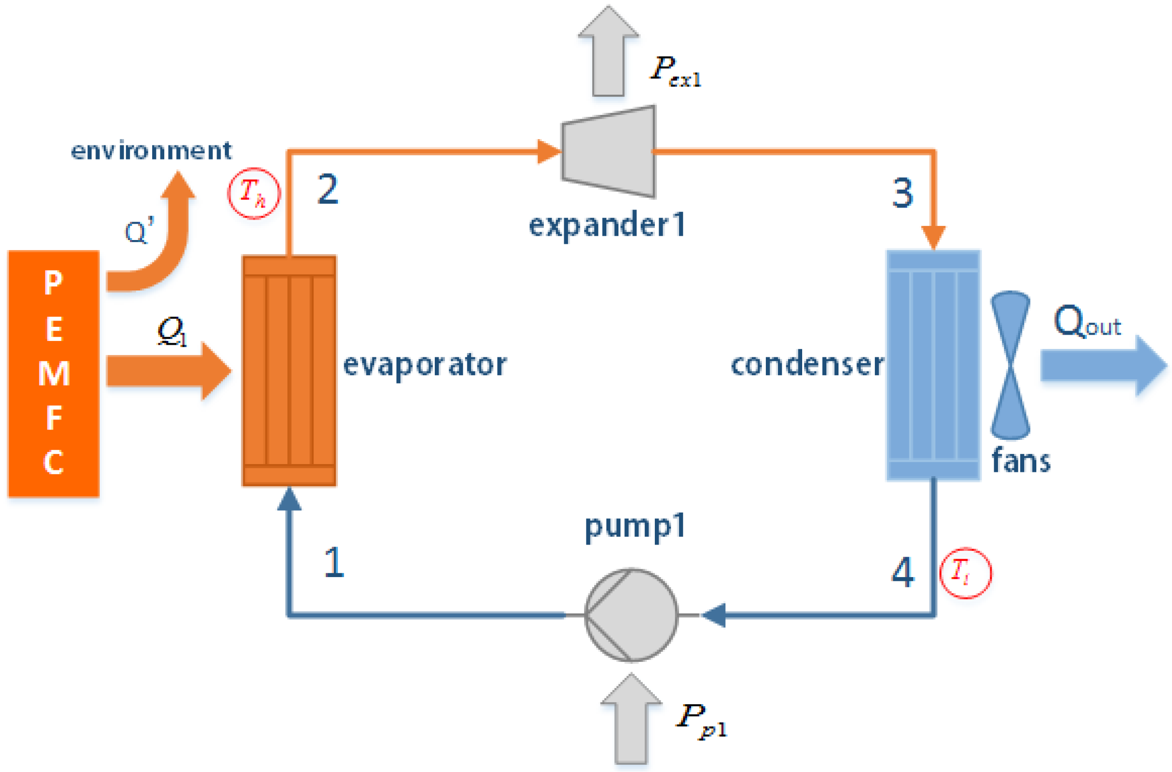
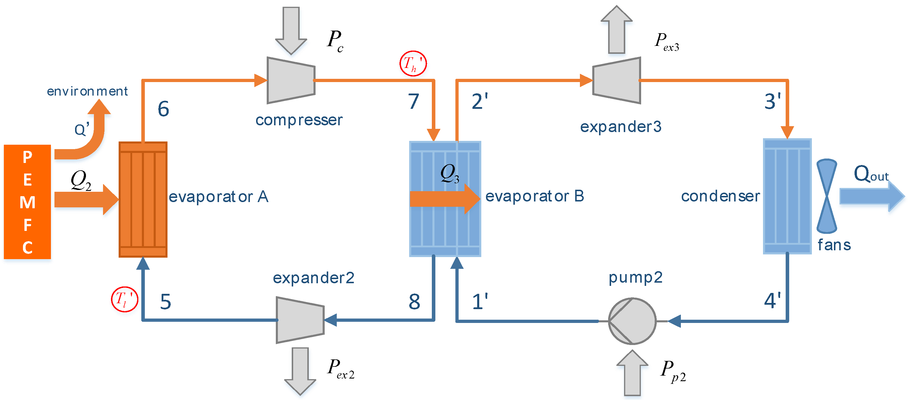
2.1. Organic Rankine Cycle (ORC) System Description

As illustrated in Figure 1, an ORC system includes an evaporator, an expander, a condenser and a pump. The marked numbers 1, 2, 3, 4 indicate the states of the working fluid, which is associated with the numbers on the temperature versus entropy diagram, as shown in Figure 2a.
The operating process of ORC is as follows:
  • The liquid phase working fluid in an ORC system recovers the heat ( Q 1 ) released from PEMFC and evaporates it to be overheated vapor. The redundant heat ( Q ) is released to the environment by another way;
  • The high pressure working fluid vapor drives the expander to generate the expansion work and relieves the pressure with the synchronously declining temperature;
  • The working fluid vapor at the low pressure is cooled to be a saturated liquid phase in the condenser by the air;
  • The saturated working fluid is pumped into the evaporator and completes the Rankine cycle.
Clearly, in this design, the evaporating temperature of ORC ( T h ) is restrained by the operating temperature of PEMFC ( T f ).

2.2. HPORC System Description

HPORC is the combination system of a HP and ORC system. The conceptual scheme of the system is shown in Figure 3. The corresponding temperature vs. entropy diagram of the HP is shown in Figure 2b as 5-6-7-8. For ORC, it is shown in Figure 2a as 1′-2′-3′-4′. The difference from the previous ORC system is that the evaporating temperature of ORC ( T h ) can break the limit of T f , which is the operating temperature of PEMFC. This may improve the thermal efficiency to a great extent. The working process of the heat pump is as follows:
  • Subcooled working fluid with low pressure recovers the heat released from PEMFC and evaporates it to be overheated vapor through the evaporator of the HP;
  • The overheated vapor is compressed to be of high temperature and pressure, and the superheat is enlarged;
  • The high-temperature vapor expresses the heat to the working fluid of the ORC system and is cooled down to a subcooled liquid phase;
  • The liquid with high pressure enters the expander and relieves the pressure.
The working process of ORC in the HPORC system (process 1′-2′-3′-4′) is similar to that in the previous ORC system (process 1-2-3-4), shown in Figure 2a. Obviously, for both ORC and HPORC systems, the thermal efficiency and the net power are mainly influenced by the system operating temperature. Particularly, in ORC, the T h is defined as the outlet temperature of the evaporator and the T l is defined as the outlet temperature of the condenser. In HPORC, the T l is defined as the inlet temperature of the heat pump evaporator. T h is defined as the outlet temperature of the compressor. The optimum working temperature of HPORC system can be obtained by calculation.

2.3. Thermal Dynamic Model

In the previous section, the concepts of ORC and HPORC systems have been introduced with the thermal dynamics models being established. In this section, the performances of these two systems are simulated numerically. For simplicity, only the most important thermodynamic properties are considered for choosing a working fluid:
  • The critical temperature of the working fluid should be above 55 °C;
  • The dry working fluid is adoptable for ORC, and the wet working fluid is better for the heat pump.
Here, we assume that the system working in negative pressure is acceptable. In the following paragraphs, five common refrigerants are considered, these being water, ethanol, R123, R245fa, and R134a. In this study, the temperature difference in the heat exchanger is set to be larger than 5 °C. Therefore, in ORC, the T l changes from 25 to 50 °C, the T h changes from 30 to 55 °C, with the condition that T l should be lower than T h . In HPORC, the T l changes from 25 to 55 °C, the T h changes from 60 to 200 °C. The models are simulated numerically on the platform of Matlab by using the NIST (National Institute of Standards and Technology) standard thermophysical property database to determine the state point of the working fluid.
The modeling in this section is assumed to be in a steady-state condition. As the goal of this paper is not to describe a system, in particular, but to proceed with two kinds of theoretical systems and compare their thermodynamic performance, the parameters and types for the components are not specified. The zero-dimension thermal dynamic models of the two systems are analyzed based on the temperature vs. entropy process diagram as depicted in Figure 2, with the following assumptions:
  • For the pump, compressor, and expander, the isentropic efficiency ηs is set to be 0.9, the mechanical efficiency ηm is assumed to be 0.8. In fact, the efficiencies are determined by the pressure ratio and mass flow rate. Designing the components according to the operating conditions will be our work in the future. The power generation efficiency of the generator connected to the expander is assumed to be 0.9.
  • The heat loss in the tube between two conjoint components of the system is ignored;
  • The heat exchange efficiency η q is set to be 0.9, the pressure drop is assumed to be 0.1 kPa.
  • The operating temperature of PEMFC is set to be 60 °C, and the temperature of the environment is kept at 20 °C;
  • The heat transfer coefficient (UA ) of evaporators is set to be 1000 W/K;
  • The condenser can meet the requirements of heat exchange. This is reasonable because the heat-transfer coefficient of the condenser can be controlled by the fans, as illustrated in Figure 1.

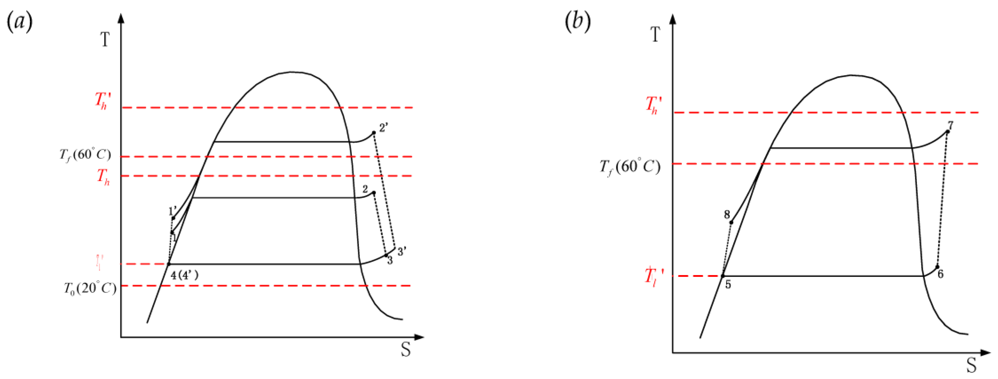
2.3.1. Model Description of ORC

Being aware of the superheat, T h and T l , we can calculate the fluid state of each point illustrated in Figure 2 by using the NIST standard thermophysical property database. The heat recovered from the fuel cell can be expressed as:
Q ˙ 1 = UA T 2 T 1 ln ( T f T 1 T f T 2 ) × η q
here, T 1 and T 2 are the temperature of the working fluid at the inlet and outlet of the evaporator as illustrated in Figure 2. T f indicates the operating temperature of the PEMFC system. The mass flow rate of the working fluid is determined by:
m ˙ 1 = Q ˙ 1 h 2 h 1
here, h 1 and h 2 indicate the entropy of the working fluid at the inlet and outlet of the evaporator, respectively. The expansion power P e x 1 and input pump power P p 1 can be expressed as:
P e x 1 = m ˙ 1 ( h 2 h 3 ) η m e x 1 P p 1 = m ˙ 1 ( h 1 h 4 ) / η m p 1
η m e x 1 and η m p 1 represent the mechanical efficiency of expander and pump as illustrated in Figure 1. h 3 and h 4 denote the entropy of the working fluid at the inlet and outlet of the condenser. Thus, the net power of the ORC system can be obtained by:
P n e t 1 = P e x 1 P p 1
The thermal efficiency η t h can be evaluated according to the following expression:
η t h = P n e t 1 Q ˙ 1

2.3.2. Model Description of HPORC

Similarly, in HPORC, the heat recovered from the fuel cell by HP can be expressed as:
Q ˙ 2 = UA T 5 T 6 ln ( T f T 6 T f T 5 ) × η q
here, T 5 and T 6 indicate the temperature of the working fluid at the inlet and outlet of the evaporator A in the HP system. The mass flow rate in the HP is then determined by:
m ˙ 2 = Q ˙ 2 h 6 h 5
h 5 and h 6 denote the entropy of the working fluid at the inlet and outlet of evaporator A, as illustrated in Figure 3. Then, the input power of the HP through the compressor is calculated according to the following expression:
P c = m ˙ 2 ( h 7 h 6 ) / η m c
here, η m c is the mechanical efficiency of compressor. The heat transferred to ORC can be evaluated by:
Q ˙ 3 = m ˙ 2 ( h 7 h 8 ) η q
The expansion power generated by expander 2 (illustrated in Figure 3) in HP is calculated by:
P e x 2 = m ˙ 2 ( h 8 h 5 ) η m e x 2
η m e x 2 is the mechanical efficiency of expander 2. Similar to the previous ORC system, the mass flow rate in the ORC part is calculated by:
m ˙ 3 = Q ˙ 3 h 2 h 1
here, h 1 and h 2 denote the entropy of the ORC working fluid at the inlet and outlet of the evaporator B, as illustrated in Figure 3. The saturation temperature in evaporator B is calculated as follows:
T s a t 1 2 = T s a t 7 8 Q ˙ 3 η q UA
here, T s a t 7 8 is the saturation temperature on the HP side of process 7-8, T s a t 1 2 is the saturation temperature on ORC side of process 1′-2′.
The expressions of the expansion power and pump power in ORC are similar as the previous ones. The net power are calculated as follows:
P n e t =    P e x 2 P c + P e x 3 P p 2
here, P e x 2 and P p 2 represent the output power and the input pump power for ORC cycle in HPORC system. Therefore, the thermal efficiency of the HPORC system can also be evaluated according to Equation (5).

2.4. Electrochemical Model of PEMFC

In this section, the electrochemical model of PEMFC is established to obtain the stack voltage V s t a c k , stack temperature T s t a c k , and the electric power P e l e . The hydrogen-oxygen fuel cell is considered in this paper. By coupling the electrochemistry model with the heat recovery system, the operating status of both PEMFC and ORC or HPORC can be numerically predicted. The system efficiency of PEMFC with a heat recovery system can be obtained. The key parameters of PEMFC are listed in Table 1. It is worthy to note that in this study the load current of PEMFC is set to be 250 A, constantly.
A PEMFC stack is the combination of 250 cells in series, and the stack voltage is the summation of the cell voltage. The cell voltage can be calculated as followed:
V c e l l = E n e r n s t V a c t V o h m i c
V s t a c k = N V c e l l
here, the voltage loss caused by the concentration difference is ignored. E n e r n s t is the Nernst voltage, which can be evaluated as follows [18]:
E N e r n s t = E 0 + Δ s n F ( T T 0 ) R T n F ln 1 P H 2 ( P O 2 ) 0.5
E 0 is the cell potential at the standard state ( P 0 = 1   atm , T 0 = 298.5   K ). Usually, E 0 = 1.229   V . R = 8.314   Jmol 1 K 1 is the universal gas constant. Δ s is the increased entropy with 1 mol H2 reacted at the standard state.
Δ s = s H 2 O ( l ) s H 2 1 2 s O 2 = 163.24   Jmol 1 K 1
n = 2 is the mole number of the electrons transferred in the cell with 1 mol H2 being reacted. F = 96 , 485   Cmol 1 is the Faraday constant. The active voltage V a c t can be calculated as follows:
V a c t = ξ 1 ξ 2 T ξ 3 T ln C O 2 ξ 4 T ln i
The values of each coefficient are [18]:
ξ 1 = 0.948
ξ 2 = 0.00286 + 0.0002 ln A + 4.310 5 ln C H 2
ξ 3 = 7.6 × 10 5
ξ 4 = 1.93 × 10 4
C O 2 and C H 2 are the concentration of O 2 and H 2 , which can be calculated through P O 2 , P H 2 by using Henry’s law. A is the active area of PEMFC, which is set to be 250 cm 2 . V o h m i c is the voltage loss caused by the electrical resistance:
V o h m i c = i A R i n
The inner resistance is calculated as follows:
R i n = r d A
here, r = 10   Ω cm is membrane resistance and d = 10   μ m is the membrane thickness. The temperature of the stack is then calculated as follows:
C t d T d t = P t o t P e l e Q ˙ c o o l
P e l e = i A V s t a c k
here,   P e l e is the electric power generated by the PEMFC. Q ˙ c o o l is the heat transferred to ORC or HPORC and the environment.

3. Results

In this study, ORC and HPORC are first simulated separately regarding PEMFC as a heat resource with constant temperature (60 °C). The performance of ORC and HPORC systems are simulated and compared with each other. The optimum working condition for each working fluid is clarified. After that, the PEMFC model is coupled with the heat recovery system to check the feasibility of ORC or HPORC acting as the cooling system.

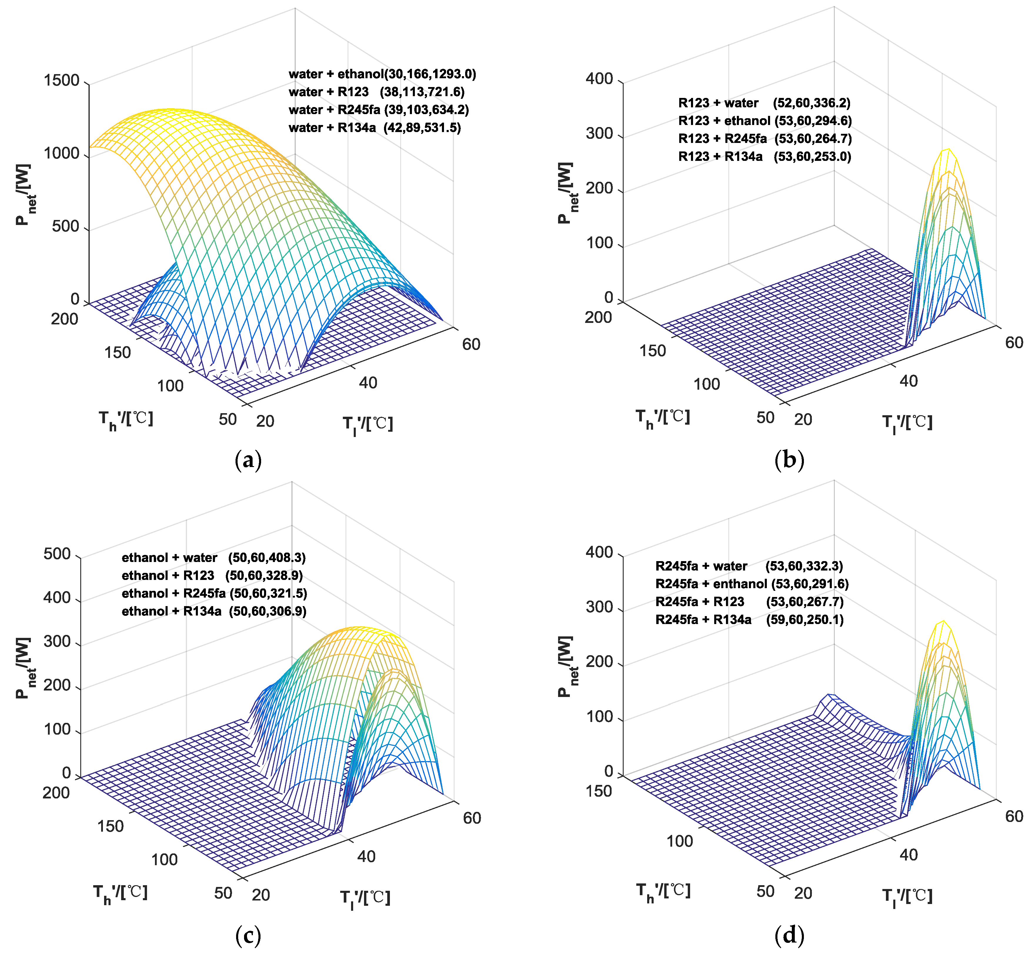
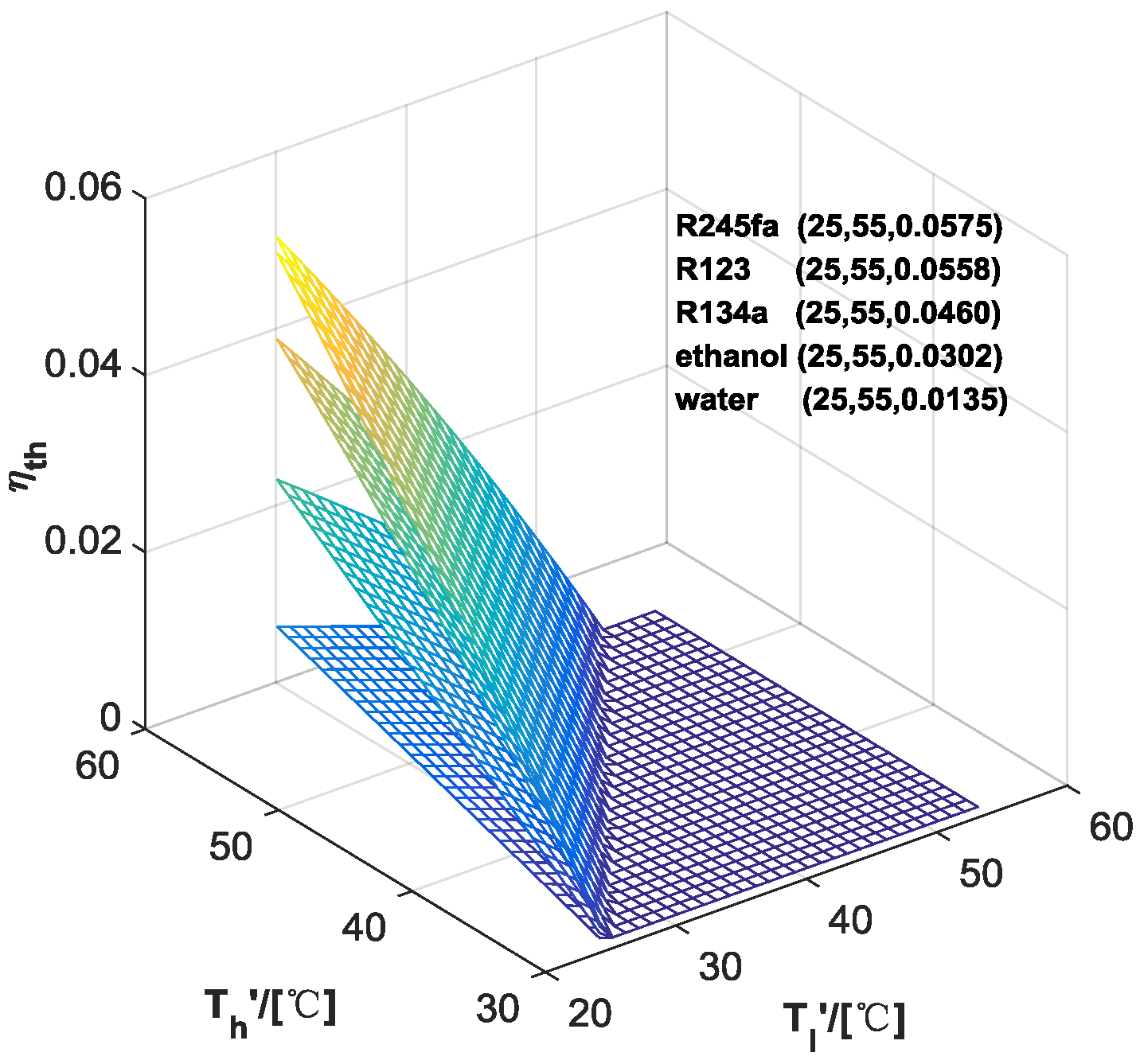
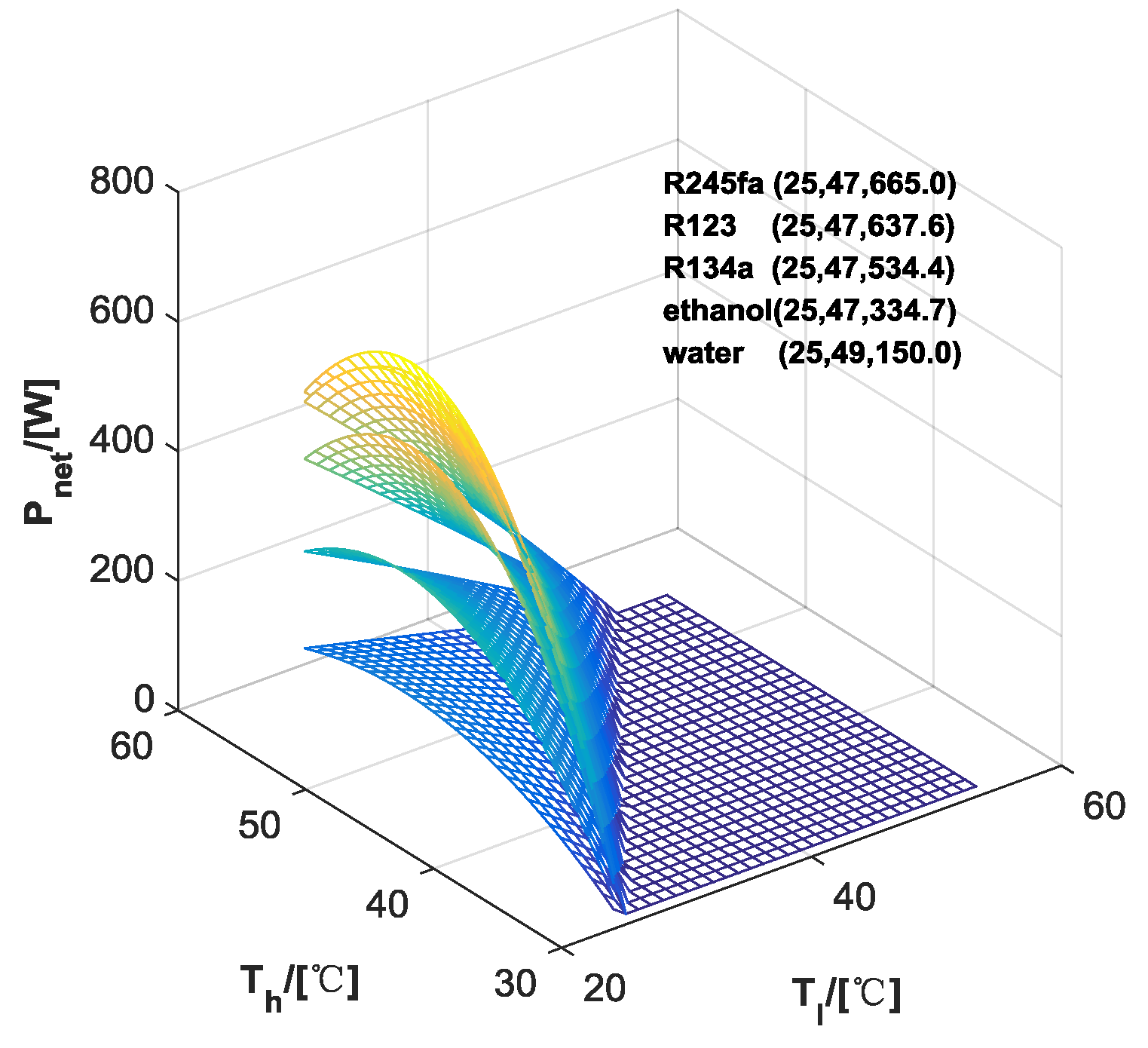
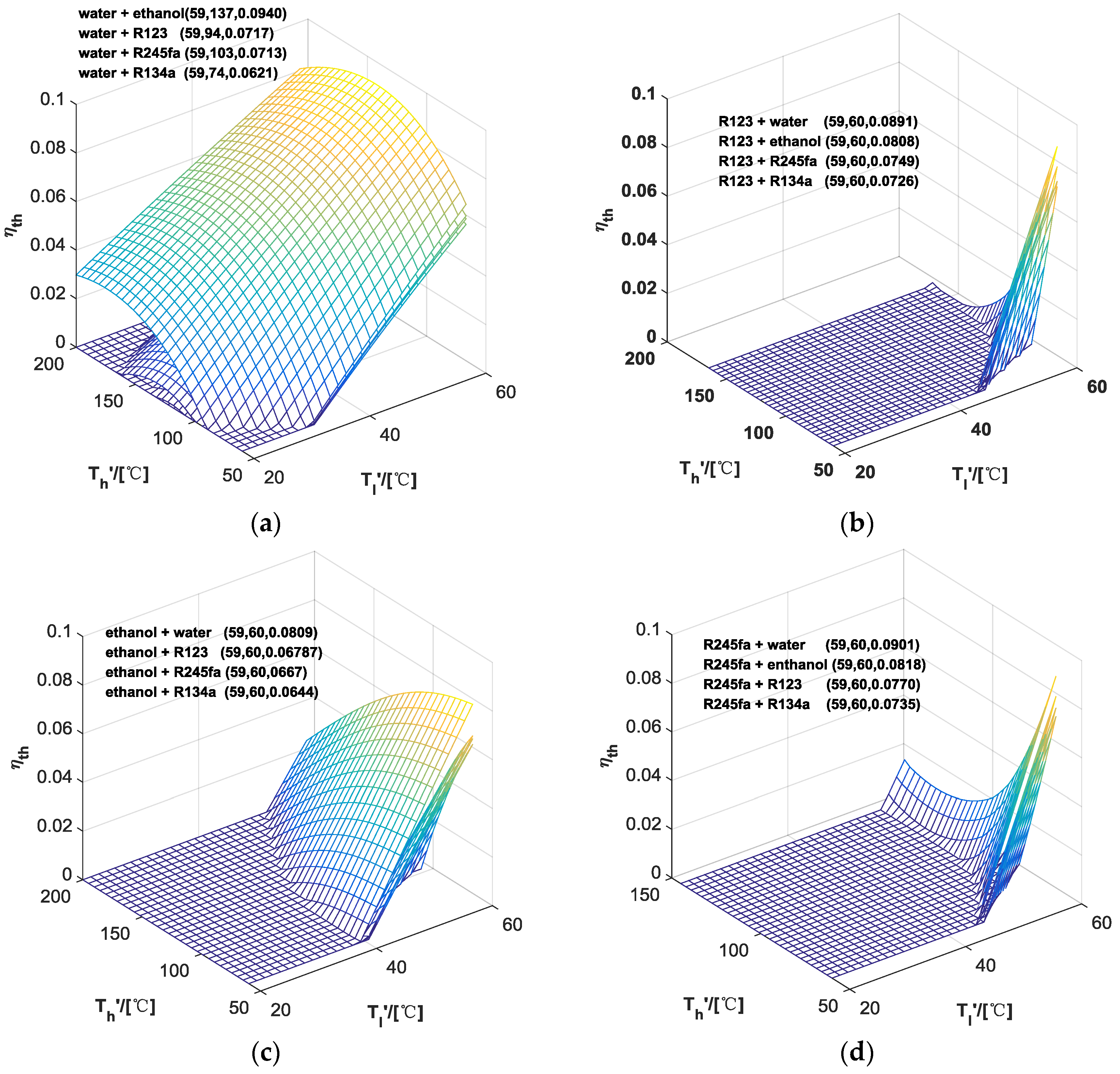
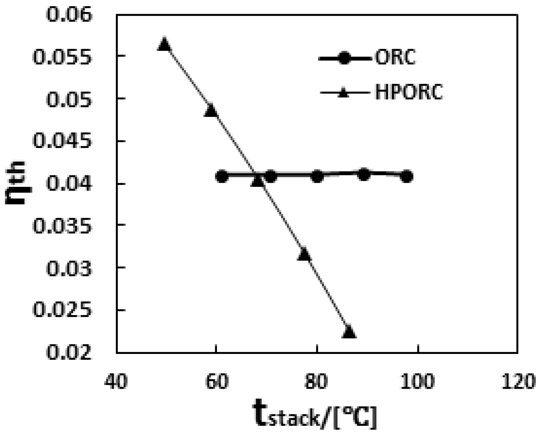
3.1. Performance of ORC

Figure 4 illustrates the relationship between thermal efficiency η t h of the ORC system with different T h and T l . As expected, the efficiency increases with increasing T h , but decreases with increasing T l . The working fluid R245fa has the highest Rankine efficiency of 5.75% with the T l  of 25 °C and T h of 55 °C. It should be noted that when the maximal thermal efficiency is achieved, the net power is relatively low because the amount of heat absorbed by the ORC system is small.
For heat recovery application, the net power is a more important specification. Figure 5 shows that a maximal net power of 665 W can be achieved with R245fa being selected as the working fluid. The corresponding temperature T l is 25 °C, and the T h is 47 °C. The thermal efficiency is 4.03%, which can be obtained from Figure 4. As illustrated in Figure 5, for each working fluid considered, there is an optimum T h under which an ORC system with maximal net power can be achieved. Physically, this is attributed to the fact that the thermal efficiency increases with increasing T h . However, the recovered heat, Q ˙ 1 , by the ORC system would decrease due to the smaller heat transfer temperature difference in the evaporator. This may lead to the existence of a peak point of net power. Moreover, the optimum value of T h is around 47 °C. Thus, we may suggest that the proper operating temperature T h is mainly determined by the heat resource rather than the thermodynamic properties of the working fluid.

3.2. Performance of HPORC

Figure 6 shows the relationship between the thermal efficiency η t h and T h , T l in the HPORC system. Since the critical temperature for R134a is too low (less than 100 °C) to be applied in the HP, the working fluid selected in the heat pump is water, R123, ethanol, and R245fa, respectively. The HP system would be under negative pressure while the water is adopted. Different working fluids are attempted in ORC. As seen in Figure 6a, when the water is adopted in the HP and the ethanol is selected in ORC, the maximal efficiency achieves 9.40% with T l = 59   ° C and T h = 137   ° C . The thermal efficiency increases with increasing T l . That is caused by the fact that the input power of the HP reduces with increasing T l . The existence of the efficiency peak point with constant T l and suitable T h can be explained by the fact that high T h leads to the high Rankin efficiency in ORC and high input power of the HP at the same time. Therefore, the final efficiency yield from these two parts is degraded when T h is increased further.
In Figure 7, for each T h , there exists the optimum value of T l for HPORC to achieve the maximal net power. When water is chosen in the HP and ethanol is adopted as the working fluid in ORC, the peak value of the net power reaches 1293 W with T l = 30   ° C and T h = 166   ° C . The corresponding efficiency is 4.73%, as illustrated in Figure 6a. Clearly, the optimum T l varies while the working fluid in ORC is changed. According to the results, we suggest that the optimum T l is between 30–40 °C with water in the HP.
The results of ORC and HPORC are compared in Table 2 and Table 3. In Table 2, the maximum thermal efficiency ηth is listed. It can be seen that the maximal thermal efficiency can approach 5.75% for ORC, while R245fa is adopted as the working fluid. In HPORC, the maximal thermal efficiency is 9.4% with water in the HP and ethanol in ORC. That means the combination of HP to ORC can dramatically improve the maximum thermal efficiency of the heat recovery system. However, the corresponding net powers cannot achieve the maximum due to the small temperature difference in the heat exchanger.
In Table 3, the maximal net powers with different working fluids are presented. For the ORC system, the maximal net power is 665 W. It is generated by the system with R245fa as the working fluid. The corresponding thermal efficiency is 4.03%. As for the HPORC system, the maximum net power is 1293 W. The corresponding thermal efficiency is 4.73%, which is much smaller than the maximum value of 9.4%. However, it’s exciting that the HP can increase the net power significantly. Physically, this is mainly attributed to the fact that more heat can be recovered from PEMFC by adding a HP system.
According to the above results, it can be seen that the heat recovery ability in both thermal efficiency and the net power can be enhanced by adding a HP system. On the one hand, it can break the temperature limit of an ORC and results in an increment of the thermal efficiency; on the other hand, it can enlarge the temperature difference in the heat transfer process, which may increase the performance of the evaporator with more heat recovered from the PEMFC.
The foregoing descriptions and calculations are based upon a PEMFC system. The heat recovery system proposed in this paper, however, can also be widely employed for other low temperature waste heat power generation applications, such as geothermal energy.

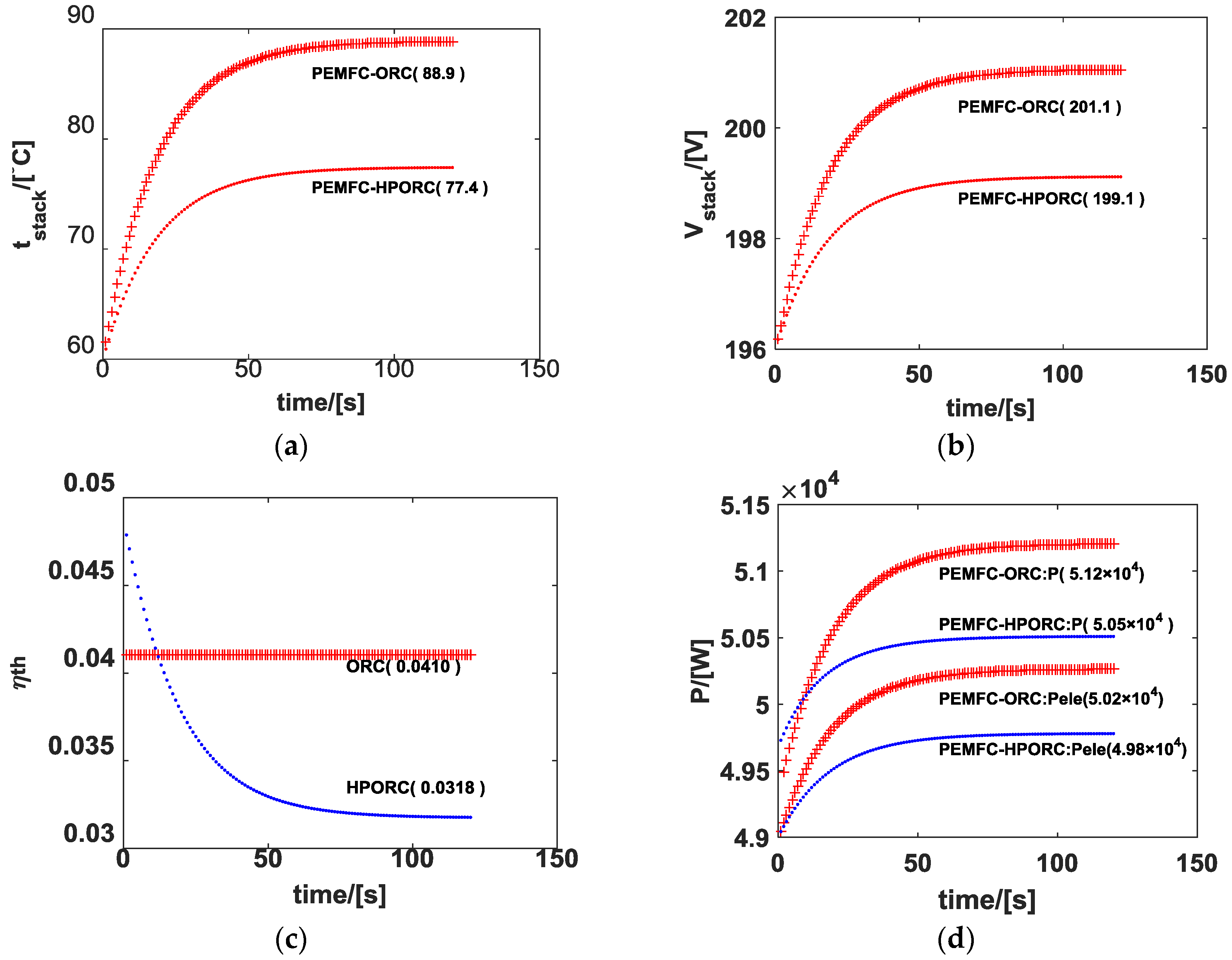
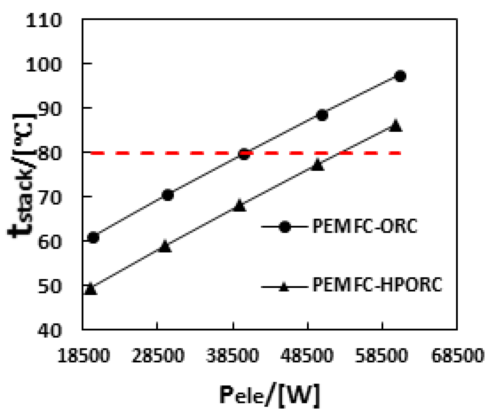
3.3. Performance of PEMFC with ORC or HPORC Acting as the Cooling System

In the previous section, the performance of the heat recovery system is simulated regarding PEMFC stack temperature as a constant (60 °C). The redundant heat is released to the environment, except for that released to ORC or HPORC. The optimum values of T l , T h , T h , and T l for each group of working fluids are proposed. In this section, we consider the performance of PEMFC with ORC or HPORC acting as the cooling system. It means the heat released from the PEMFC stack is assumed to be wholly recovered by the ORC or HPORC system. The optimum values of T l , T h , T l , and T h obtained in previous section are adopted. For the ORC system, it has been shown that R245fa is an ideal choice. The optimum T l is 25 °C, and the optimum T h is 47 °C. For the HPORC system, where water is adopted in HP and ethanol in ORC, the optimum T l is 30 °C, and the optimum T h is 166 °C.
Figure 8 shows the results when ORC and HPORC are coupled to PEMFC as the cooling system. The stack is loaded with a current of 250 A. The stack initial temperature is assumed to be 60 °C. In Figure 8a, it can be seen that the PEMFC stack temperature approaches 88.9 °C at the final steady state with ORC and 77.4 °C with HPORC. The result shows that in this case, ORC is not capable of cooling down the PEMFC properly. High temperature (e.g., larger than 80 °C) will cause the dehydration of the membrane and the damage of the PEMFC. However, HPORC possesses a good cooling ability due to the higher temperature difference between PEMFC and the fluid in the evaporator of the HP. In Figure 8b, with HPORC, the stack voltage is 199.1 V, which is a little bit lower than that with ORC. It is worthy to note that the thermal efficiency of ORC is constant since it depends on the value of T h and T l , as illustrated in Figure 8c. However, it’s different for HPORC. As time goes by, the stack temperature increases and the transferred heat from PEMFC increases. In order to satisfy the cooling demand of process 7-8 in HP, the evaporating temperature of ORC has to be reduced by controlling the pressure ratio of pump and expander, which leads to a decrease of the thermal efficiency. In Figure 8d, it’s shown that when HPORC is adopted, the electric power is 49.8 kW of PEMFC and 50.5 kW by PEMFC and HPORC. It is a little bit lower than that of PEMFC coupled with ORC system. Though PEMFC-ORC has higher efficiency and net power, the high operating temperature indicates that ORC is not capable in this case.
Figure 9 shows the stack temperature when ORC and HPORC are used with PEMFC of different power. Obviously, ORC can only be available while PEMFC power is relatively low. Figure 10 shows that HPORC processes at a higher efficiency when the temperature of PEMFC is 67 °C. However, it should be noted that the results are based on the T l , T h , T h , and T l in Section 2.1 and Section 2.2, where the temperature of PEMFC is assumed to be 60 °C. By optimizing the T l , T h , T h , and T l according to the real working temperature of PEMFC, the system efficiency could be improved.

4. Conclusions

In this study, two waste heat recovery systems for PEMFC are presented, named ORC and HPORC. The performances of both ORC and HPORC systems are simulated with several potential working fluids, such as R123, R245fa, R134a, water, and ethanol being considered. The results show that when the stack temperature is kept at a constant, such as 60 °C, the best performance of the ORC system can be achieved with R245fa being adopted as the working fluid. The maximal net power can approaches 665 W. The corresponding thermal efficiency is 4.03%. For the HPORC system, the maximal net power can reach 1293 W when water is adopted as the working fluid for HP and ethanol for ORC, respectively. The corresponding thermal efficiency is 4.73%.
Moreover, the possibility of using ORC as the cooling system of PEMFC is also studied. The PEMFC stack is loaded with constant current. The released heat is assumed to be totally recovered by ORC and HPORC. When ORC is adopted as the cooling system, the stack temperature is 88.9 °C, the stack voltage is 201.1 V and the thermal efficiency is 4.1%. When the HPORC acts as the cooling system, the stack temperature is 77.4 °C, the stack voltage is 199.1 V, and the thermal efficiency is 3.2%. The result indicates that the temperature control ability of the HPORC system would be much better than ORC system. It can be concluded that the HPORC system is much more feasible for the cooling system of a PEMFC stack.
It should be noted that in this study we were mainly concerned with the thermodynamic feasibility of recovering the waste heat of PEMFC by ORC and HPORC theoretically. The above results were obtained under ideal conditions. This means that the energy loss in pipe is ignored. The negative pressure in the system is acceptable. It’s proven that ORC and HPORC are feasible and can improve the electric efficiency of PEMFC. In the future, the influence of the components, such as pump and expander, will be exploited. The parameter optimization will be considered in order to increase the efficiencies of the components and the overall system and provide valuable suggestions for system design and component selection.

Acknowledgments

The authors acknowledge the support from the NSFC (National Natural Science Foundation of China) grant No. U1564209.

Author Contributions

Yangjun Zhang and Weilin Zhuge conceived the system; Tianqi He, Rongqi Shi and Jie Peng performed the system design and numerical simulation; Tianqi He wrote the paper.

Conflicts of Interest

The authors declare no conflict of interest. The founding sponsors had no role in the design of the study; in the collection, analyses, or interpretation of data; in the writing of the manuscript, and in the decision to publish the results.

Abbreviations

The following abbreviations are used in this manuscript:
PEMFCProton exchange membrane fuel cell
ORCOrganic Rankine cycle
HPORCHeat pump combined organic Rankine cycle
HPHeat pump
CHPCombined heat and power
FCVFuel cell vehicle
SOFCFSolid oxide fuel cell

Nomenclature

Symbols
A area (cm2)
P power (W)
Q ˙ heat flow rate (W)
m ˙ mass flow rate (kg/s)
T temperature (K)
UA heat transfer coefficient (W/K)
V voltage (V)
η efficiency
Subscripts, Abbreviations
actactive
ccompressor
eleelectric
exexpander
ggenerator
hhigh
llow
mmass, mechanical
netnet power
ostandard state
ppump
qquantity of heat
tottotal
ththermal

References

  1. Kandlikar, S.G.; Lu, Z. Thermal management issues in a PEMFC stack—A brief review of current status. Appl. Therm. Eng. 2009, 29, 1276–1280. [Google Scholar] [CrossRef]
  2. Zakaria, I.A.; Mustaffa, M.R. Steady-state potential energy recovery modeling of an open cathode PEM fuel cell vehicle. Appl. Mech. Mater. 2014, 465, 114–119. [Google Scholar] [CrossRef]
  3. Colmenar-Santos, A.; Alberdi-Jiménez, L.; Nasarre-Cortés, L.; Mora-Larramona, L. Residual heat use generated by a 12 kW fuel cell in an electric vehicle heating system. Energy 2014, 68, 182–190. [Google Scholar] [CrossRef]
  4. Massardo, A.F.; Lubelli, F. Internal reforming solid oxide fuel cell-gas turbine combined cycles (IRSOFC-GT): Part A—Cell model and cycle thermodynamic analysis. J. Eng. Gas Turbines Power 2000, 122, 27–35. [Google Scholar] [CrossRef]
  5. Yu, S.; Han, J. A dynamic model of PEMFC system for the simulation of residential power generation. J. Fuel Cell Sci. Technol. 2010, 7. [Google Scholar] [CrossRef]
  6. Shabani, B.; Andrews, J. An experimental investigation of a PEM fuel cell to supply both heat and power in a solar-hydrogen RAPS system. Int. J. Hydrog. Energy 2011, 36, 5442–5452. [Google Scholar] [CrossRef]
  7. Nguyen, T.V.; White, R.E. A water and heat management model for proton exchange membrane fuel cells. J. Electrochem. Soc. 1993, 140, 2178–2186. [Google Scholar] [CrossRef]
  8. Cao, Y.; Guo, Z. Performance evaluation of an energy recovery system for fuel reforming of PEM fuel cell power plants. J. Power Sources 2002, 109, 287–293. [Google Scholar] [CrossRef]
  9. Yu, S.; Jung, D. Thermal management strategy for a proton exchange membrane fuel cell system with a large active cell area. Renew. Energy 2008, 33, 2540–2548. [Google Scholar] [CrossRef]
  10. Zong, Y.; Zhou, B. Water and thermal management in a single PEM fuel cell with non-uniform stack temperature. J. Power Sources 2006, 161, 143–159. [Google Scholar] [CrossRef]
  11. Briguglio, N.; Ferraro, M. Evaluation of a low temperature fuel cell system for residential CHP. Int. J. Hydrog. Energy 2011, 36, 8023–8029. [Google Scholar] [CrossRef]
  12. Yang, K.; Zhang, H. Study of zeotropic mixtures of ORC (organic Rankine cycle) under engine various operating conditions. Energy 2013, 58, 494–510. [Google Scholar] [CrossRef]
  13. Ringler, J.; Seifert, M. Rankine Cycle for Waste Heat Recovery of IC Engines. SAE Int. J. Engines 2009, 2, 67–79. [Google Scholar]
  14. Quoilin, S.; Aumann, R. Dynamic modeling and optimal control strategy of waste heat recovery Organic Rankine Cycles. Appl. Energy 2011, 88, 2183–2190. [Google Scholar] [CrossRef]
  15. Chen, P.C. The dynamics analysis and controller design for the PEM fuel cell under gas flowrate constraints. Int. J. Hydrog. Energy 2011, 36, 3110–3122. [Google Scholar] [CrossRef]
  16. Uzunoglu, M.; Alam, M.S. Dynamic modeling, design, and simulation of a combined PEM fuel cell and ultracapacitor system for stand-alone residential applications. Energy Convers. 2006, 21, 767–775. [Google Scholar] [CrossRef]
  17. Liu, B.T.; Chien, K.H. Effect of working fluids on organic Rankine cycle for waste heat recovery. Energy 2004, 29, 1207–1217. [Google Scholar] [CrossRef]
  18. Mann, R.F.; Amphlett, J.C.; Hooper, M.A.I. Development and application of a generalized steady-state electrochemical model for a PEM fuel cell. J. Power Sources 2000, 86, 173–180. [Google Scholar] [CrossRef]
Figure 1. Schematic diagram of an ORC system.
Energies 09 00267 g001
Figure 2. Temperature vs. entropy diagram: (a) T-S diagram of ORC; (b) T-S diagram of HP system. Here, T f denotes the temperature of PEMFC, T 0 is the environment temperature.
Energies 09 00267 g002
Figure 3. Schematic diagram of a HPORC system.
Energies 09 00267 g003
Figure 4. The thermal efficiency η t h with different T l and T h in ORC; the numbers in brackets are ( T l , T h , η t h ).
Energies 09 00267 g004
Figure 5. The net power P n e t with different T l and T h in ORC; the numbers in brackets are ( T l , T h , P n e t ).
Energies 09 00267 g005
Figure 6. The thermal efficiency η t h with different T l and T h in HPORC. “A + B” indicates that “A” is the working fluid selected in HP and “B” is selected in ORC. The numbers in brackets are ( T l ,   T h ,   η t h ). (a) Water in HP and organic fluids in ORC; (b) R123 in HP and organic fluids in ORC; (c) Ethanol in HP and organic fluids in ORC; (d) R245fa in HP and organic fluids in ORC.
Energies 09 00267 g006
Figure 7. The net power P n e t with different T l and T h in HPORC. “A + B” means “A” is selected in the heat pump, “B” is selected in ORC. The numbers in brackets are ( T l ,   T h ,   P n e t ): (a) Water in HP and organic fluids in ORC; (b) R123 in HP and organic fluids in ORC; (c) Ethanol in HP and organic fluids in ORC; (d) R245fa in HP and organic fluids in ORC.
Energies 09 00267 g007
Figure 8. Results when ORC and HPORC are coupled to PEMFC. (a) PEMFC stack temperature; (b) PEMFC stack voltage; (c) The thermal efficiency of ORC and HPORC; (d) The electric power, where P is the electric power including those generated by ORC or HPORC; P e l e is the pure electric power of PEMFC.
Energies 09 00267 g008
Figure 9. Stack temperature with different powers of PEMFC.
Energies 09 00267 g009
Figure 10. Thermal efficiency of ORC and HPORC in different stack temperatures.
Energies 09 00267 g010
Table 1. Key parameters of proton exchange membrane fuel cell (PEMFC).
SymbolsExplainationsValues
A reaction area250 cm2
C t heat capacity17.9 kJ/K
i current density1 A/cm2
d membrane thickness10 μm
N number of cells250
P H 2 partial pressure of H2 at the reaction surface1.5 atm
P O 2 partial pressure of O2 at the reaction surface2 atm
r membrane resistance10 Ωcm
Table 2. The maximum thermal efficiency η t h ( % ) for ORC and HPORC when different working fluids are selected. The first line presents the value for ORC.
ORCWaterEthanolR123R245faR134a
HP
-1.353.025.585.754.60
Water-9.407.177.136.21
Ethanol8.09-6.796.676.44
R1238.918.08-7.497.26
R245fa9.018.187.70-7.35
Table 3. The maximal net power P n e t (W) of ORC and HPORC. The first line presents the value for ORC.
ORCWaterEthanolR123R245faR134a
HP
-150.0334.7637.6665.0534.4
Water-1293.0721.6634.2531.5
Ethanol408.3-328.9321.5306.9
R123336.2294.6-264.7253
R245fa332.3291.6267.6-250.1

