Article

Rock-Breaking Properties of Multi-Nozzle Bits for Tree-Type Drilling in Underground Coal Mines

1
State Key Laboratory of Coal Mine Disaster Dynamics and Control, Chongqing University, Chongqing 400044, China
2
National & Local Joint Engineering Laboratory of Gas Drainage in Complex Coal Seam, Chongqing University, Chongqing 400044, China
*
Author to whom correspondence should be addressed.
Energies 2016, 9(4), 249; https://doi.org/10.3390/en9040249
Submission received: 16 February 2016 / Revised: 22 March 2016 / Accepted: 23 March 2016 / Published: 30 March 2016

Abstract

:
Tree-type drilling is a new technique for drilling radial tree-type boreholes in coal seams in underground mines using water jets to break the coal. The aim is to drain gas from the coal seams in larger quantities and from larger areas than can be done by conventional gas drainage using single boreholes. The self-propelled drill bit is the most important component for this technique. The bit generates a self-propelling force to move forward, break coal, and form a borehole. This paper investigates the relationships between the physical parameters of the forward nozzles in the bit and the diameter and shape of the borehole drilled. The effect of different physical parameters on the rock-breaking efficiency is studied by conducting drilling experiments. The results show that the size, orientation and number of the nozzles significantly affect the rock-breaking efficiency of the bit. To obtain a better rock-breaking efficiency under the experimental conditions used for this paper, the axial angle for forward nozzles should be 15°, the radial angle 90°, and nozzles should be arranged 2.1 mm from the center of a 12 mm drill bit. The experimental results provide a reference for the design of multi-nozzle bits for many applications such as radial jet drilling (RJD) and bent pipe cleaning.

1. Introduction

Coalbed methane (CBM), an unconventional gas, is a clean and efficient energy source. China’s CBM reserves are estimated to be 36.81 trillion m3 [1]. The Chinese government is very interested in exploiting CBM resources for a number of reasons: CBM drainage allows a valuable energy resource to be extracted and used and extraction can also lessen greenhouse gas emissions. Additionally, degassing coal mines can reduce the occurrence of mine disasters like gas explosions and outbursts [2,3,4]. Unfortunately, many of the coal seams in China are at great depths and under high ground stress. This means that underground drainage is the only viable approach for extracting both CBM and the coal economically [5,6,7].
The main technique used for underground CBM drainage is gas drainage holes bored into the coal seams. Cross-measure boreholes are one such technique [8,9], boreholes usually drilled from the floor roadway or drilling field. However, this technique has a number of problems [10,11,12,13]. Among the problems are: (1) drilling the holes is dangerous because there has been no gas pre-drainage; (2) a very large number of boreholes have to be drilled to drain the gas from a significant portion of any seam. This results in a huge and costly engineering effort and takes a great deal of time; (3) a large number of drill holes are required because gas extraction from a single borehole is low and the area drained by each hole is small. To solve these problems, a new technique for gas drainage has been proposed that can create radial tree-type boreholes by utilizing water jets to break the coal and drill holes in the coal seams. As shown in Figure 1, a whipstock is placed in a conventional gas drainage borehole (called the main borehole in this paper). Then a self-propelled bit at the end of a flexible high-pressure hose is inserted into the main borehole drill pipe, run through whipstock, and then used to drill tree-type sub-boreholes perpendicular to the main borehole. By changing the position and orientation of the whipstock, a series of radial tree-type boreholes can be completed as shown in plan A-A (Figure 1). A detailed description of the drilling processes is provided in [14]. The self-propelled bit is without doubt the most critical piece of technology for drilling tree-type boreholes. It both breaks the rock to form the tree-type sub-borehole and also generates the self-propelling force to move forward.
The type of multi-nozzle bit discussed in this paper is a highly efficient self-propelled bit that has both forward and backward pointing nozzles. It is small enough to pass through the whipstock to drill the sub-boreholes. In addition, its effective standoff distance is long and the attenuation of the jet’s rock-breaking energy is low; it is very efficient at breaking rock [15]. In order to improve bit performance, it is important to study the rock-breaking capability and self-propelling capacity of multi-nozzle bits. Buset [16] and William [17] studied the rock-breaking mechanism and self-propelled ability of multi-nozzle bits. Liao et al. [18] analyzed the effect of hydraulic parameters (erosion time, jet pressure drop, standoff distance, and confining pressure) on the rock-breaking efficiency of multi-nozzle bits. Li et al. [19,20,21] discussed the self-propelling mechanism and the horizontal drilling capacity of multi-nozzle bits and generated a model for calculating the self-propelling force. Hu et al. [22] and Liu et al. [23] used numerical simulations of multi-nozzle bits to study the internal and external flow field of the water and the how the bits broke rock to make the boreholes. However, there are numerous parameters that affect the rock-breaking efficiency of multi-nozzle bits and there are few studies that analyze how the geometry and size of the forward nozzles influence rock-breaking efficiency. Moreover, the structural parameters of the bit that determine its rock-breaking efficiency have not been studied systematically.
This paper focuses on how the size and orientation of the forward nozzles in a multi-nozzle bit affect its rock-breaking efficiency by conducting the orthogonal experiments with different nozzle size, number and orientation. The research results will be helpful for designing multi-nozzle bits for use in any context such as radial jet drilling (RJD) or bent pipe cleaning.

2. Analysis of the Rock-Breaking Capacity of Multi-Nozzle Bits

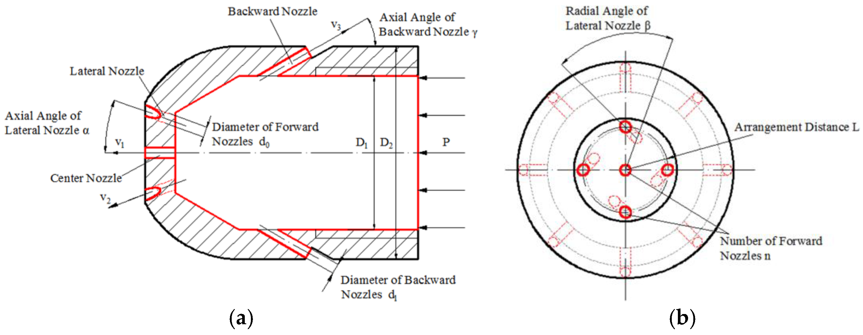
A simplified structural diagram for a multi-nozzle bit is shown in Figure 2. The important parameters of the forward nozzles are their diameter, d0, their number, n, the axial angle, α, the radial angle, β, and their arrangement distance, L (arrangement distance is how far they are from the center of the bit). They affect the rock-breaking jets velocities (including three-dimensional components of jet velocity and the jet energy distribution) and the synergy of multiple jets of a multi-nozzle bit. The velocities and synergy determine both the drilling efficiency and the diameter of the sub-borehole drilled by a bit. Therefore, the rock-breaking capacity of a multi-nozzle bit is directly related to these parameters. To analyze the rock-breaking capacity of multi-nozzle bits, this paper studies the relationships between these nozzle parameters and rock-breaking efficiency by looking at the energy transferred by the forward jets and the diameter and volume of the sub-borehole produced.

2.1. The Analysis of Rock-Breaking Velocity of Multi-Nozzle Bits

The magnitude of rock-breaking jet velocity in a multi-nozzle bit determines how much rock-breaking energy is delivered to the target rock. The distribution of three-dimensional velocity components (axial, radial, and tangential velocity components) affects the mode in which the rock fails. To investigate the rock-breaking capacity of multi-nozzle bits, it is necessary to find out the relationship between the structural parameters of forward nozzles in a bit and rock-breaking velocity.
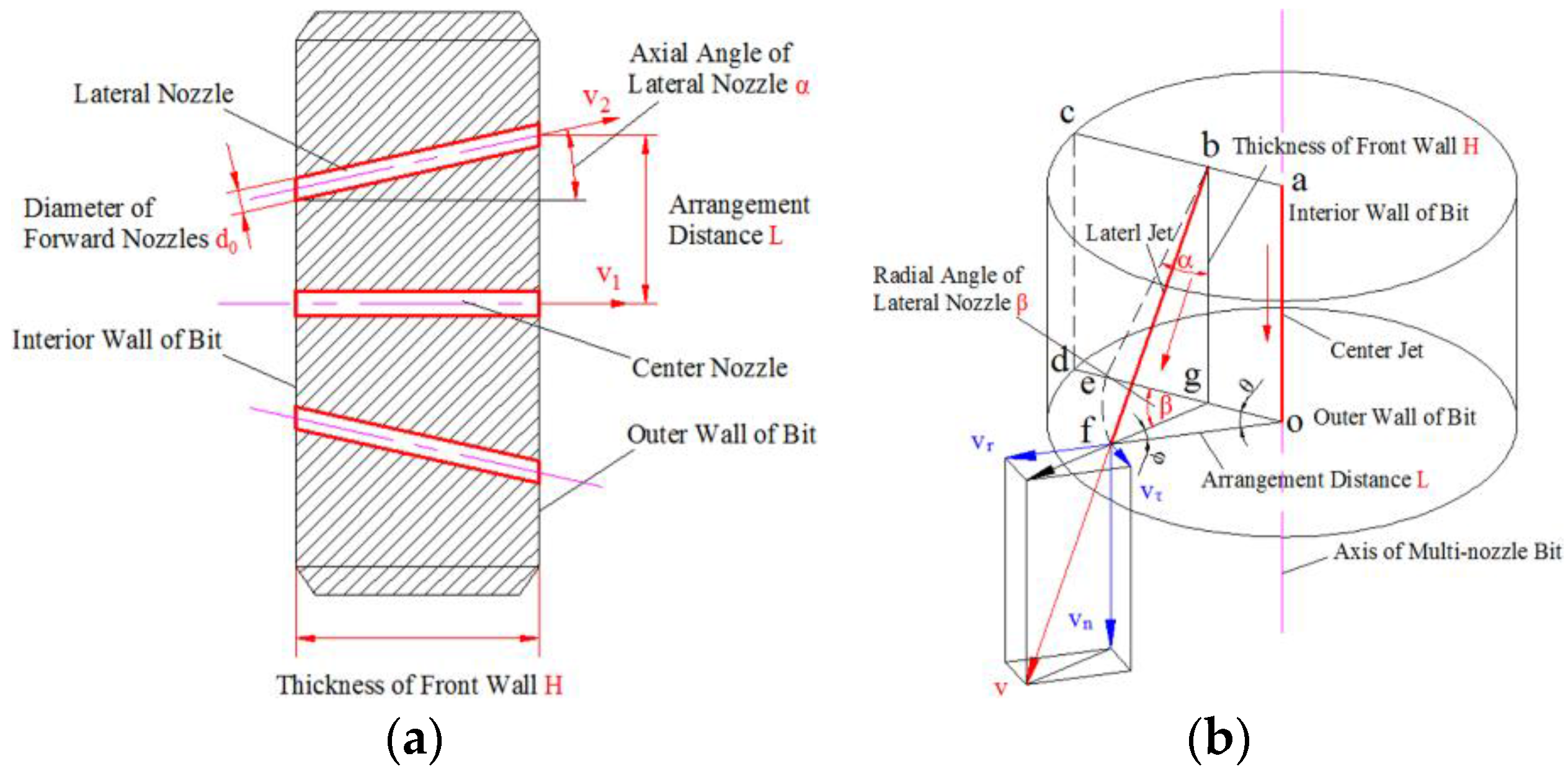
A structural diagram of the forward nozzles in a multi-nozzle bit is shown in Figure 3. The thickness of the front wall, H, is limited by the overall size of the bit; it is regarded as a constant and does not influence the bit’s rock-breaking efficiency. As shown in Figure 3, the diameter d0, number n, axial angle α, radial angle β, and the arrangement distance L of the forward nozzles will affect the three-dimensional components of jet velocity and the jet energy distribution. These determine the rock-breaking and drilling efficiency of the bit.
In Figure 3, v indicates the average exit speed of fluid from the lateral jets. The axial velocity component vn, the radial velocity component vr, and tangential velocity component vτ can be calculated from the following equations:
v n = v cos α
v r = v sin α cos φ
v τ = v sin α sin φ
where v is the exit speed of jet, × 103 m/s; α is the axial angle of forward nozzles, degrees; and φ is an auxiliary angle, degrees.
The relationship between the jet velocity v and flow rate Q is:
v = 4 Q n π d 0 2
where d0 is the diameter of a single forward nozzle, mm; Q is the flow rate of bit, L/s; and n is the number of forward nozzles.
In addition, in right triangle bfg (Figure 3b) there exists:
f g ¯ = b g ¯ tan α = H tan α
where H is the thickness of front wall of multi-nozzle bit, mm.
In triangle ofg, the angle θ is calculated from the Sine Theorem as:
θ = arcsin H tan α sin β L
where β is the radial angle of forward nozzles, degrees; and L is the arrangement distance, mm.
Using the equations above, the relationship of the auxiliary angle φ and the radial angle β can be expressed as:
φ = β θ = β arcsin H tan α sin β L
Thus, the following equations can be derived by combining the equations above:
v n = 4 Q cos α n π d 0 2
v r = 4 Q sin α n π d 0 2 × cos ( β arcsin H tan α sin β L )
v τ = 4 Q sin α n π d 0 2 × sin ( β arcsin H tan α sin β L )
It can be seen from Equations (8)–(10) that the geometry of the forward nozzles is closely related to rock-breaking velocity; and it is the orientation and distribution of the axial, radial, and tangential velocity components of the forward jets that determine the rock-breaking efficiency of the multi-nozzle bit. This lays a foundation for designing the orthogonal experiments in next sections and is helpful for analyzing the effects of structural parameters of forward nozzles on rock-breaking efficiency.

2.2. The Analysis of the Diameter of a Borehole Formed by a Multi-Nozzle Bit

The diameter of a borehole produced by a multi-nozzle bit is an important evaluation indexes for rock-breaking efficiency. Because it determines whether the multi-nozzle bit can pass through the sub-borehole, and it also affects the resistance that the multi-nozzle bit with a high-pressure hose continue drilling. Therefore, it is worth studying the relationship between the physical parameters of forward nozzles and the diameter of a sub-borehole.
When drilling a borehole with a multi-nozzle bit, a line extending along the axis of each single jet is considered to indicate the initial rock-breaking point on the surface of the rock. As drilling continues, the individual areas of broken rock around the initial points expand and deepen. Finally, the broken zones become connected to form a borehole with a certain diameter. The diameter of the borehole must be large enough to allow the multi-nozzle bit and the high-pressure hose to pass through and also large enough to allow rock debris to be discharged easily. The hole must also avoid hampering the return flow from the backward jets. Because the borehole is not truly circular, the diameter of a circle inscribed in the borehole is defined as the effective diameter D.
As shown in Figure 4, depending on how the multi-nozzle bit is constructed, for an appropriate standoff distance, E is the broken zones made by each individual jet will overlap to make a connected borehole. If it is assumed that the points where the lateral jets impact the rock surface can be regarded as the boundary of effective diameter D, then in right triangle bhi (Figure 4, right):
h i ¯ = ( H + E ) tan α
where E is the standoff distance, mm.
In triangle ofg, the following equation can be obtained through the Sine Theorem:
i j ¯ = o g ¯ = L sin ( β arcsin H tan α sin β L ) sin β
Therefore, in triangle hij, the effective diameter D can be derived through the Cosine Theorem as follows:
D = 2 × [ L 2 sin 2 ( β arcsin H tan α sin β L ) sin 2 β + ( H + E ) 2 tan 2 α + 2 × L ( H + E ) tan α sin ( β arcsin H tan α sin β L ) sin β cos β ] 1 / 2
where D is the effective diameter, in mm.
Equation (13) shows the relationship between the diameter of a borehole formed by a multi-nozzle bit and the orientations of the forward nozzles. Multi-nozzle bits can pass through the borehole and drill continuous holes only when hole diameter D is larger than the outer diameter of the multi-nozzle bit, D2. The larger the hole diameter, the easier it is to discharge rock debris and the smaller the resistance as the multi-nozzle bit and attached high-pressure hose continue drilling. Therefore, the diameter of the borehole is one of the evaluation indexes for rock-breaking efficiency. The depth and volume of the borehole are also important; together these three criteria constitute a measure of the rock-breaking efficiency. Meanwhile, this is helpful for designing experiments and analyzing experimental results.

3. Materials and Methods

To study the influence of the design of the forward nozzles on rock-breaking efficiency, rock-breaking experiments were conducted. These experiments investigated the size, the orientation and the number of nozzle orifices, an experimental design known as an orthogonal experiment.

3.1. Parameters of the Multi-Nozzle Bit

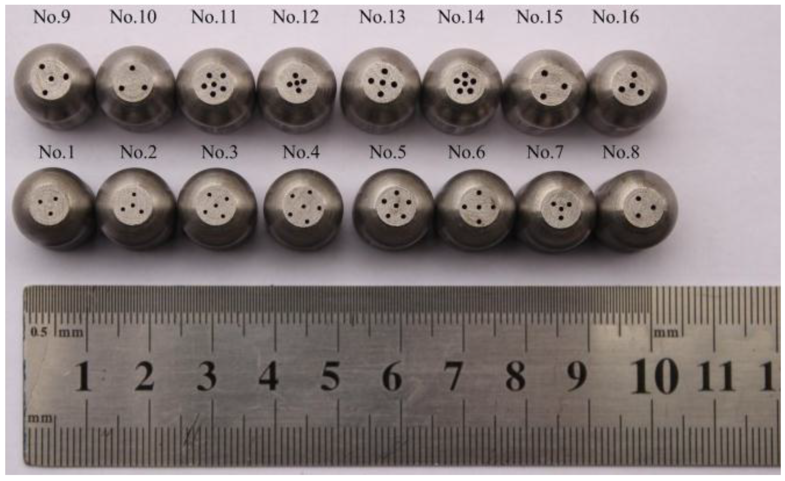
As demonstrated by Equations (8)–(10) and (13), two of the important design features of forward nozzles include the diameter, d0, and the number of nozzles, n, where n = nl + nc. nl is the number of lateral nozzles and nc the number of center nozzles (there is commonly just one center nozzle along the axis of the bit). Other important parameters include the axial angle α, the radial angle β, and the arrangement distance L. All of these parameters influence rock-breaking efficiency. In the experiments, the five parameters just mentioned are regarded as the variables and every variable is given four different values (levels) (Table 1). For each level, the diameters of multi-nozzles and the arrangement of lateral nozzles are the same. Based on five factors and four levels, an orthogonal array, L16(45), was generated to determine the factor values for the forward nozzles (Table 2) [24]. Figure 5 is a photo of the multi-nozzle bits used for the experiments.

3.2. Experimental Apparatus and Procedures

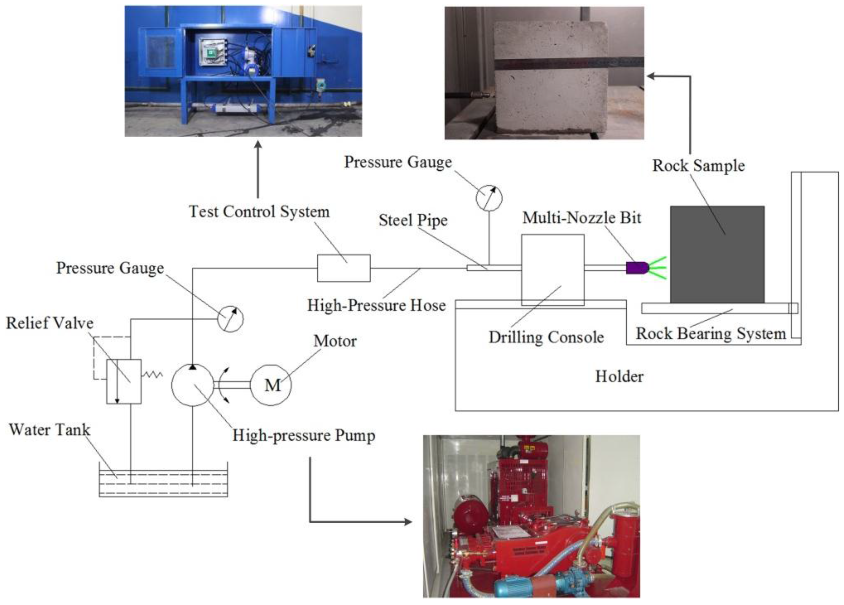
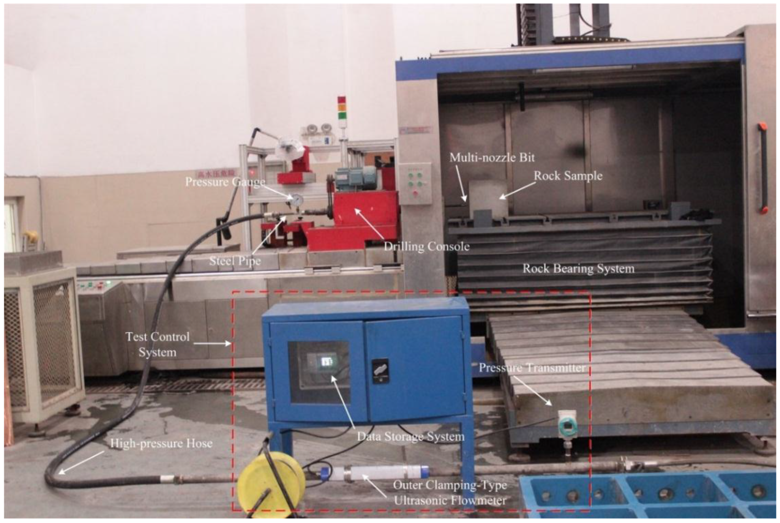
The experiments were conducted in the Laboratory of High-pressure Water Jets at Chongqing University, China. A schematic of the rock breaking test system is shown in Figure 6. The system itself is shown in a photograph in Figure 7. The main components of the experimental system include a high-pressure pump, pressure gauges, a test control system (described below), high-pressure hoses, and a custom-designed water jet test system. The main performance parameters of the test apparatus and the experimental procedures are described below:
a)
High-pressure pump. This is a high-performance pump manufactured in the United States with a peak pressure of 134 MPa and a flow rate of 104 L/min.
b)
Test control system. For monitoring the pressure and flow at all times during the experiment, a system for pressure and flow control was designed. It consists of a pressure transmitter, an outer clamping-type ultrasonic flowmeter, a data storage system, and data process and analysis software. The system is capable of testing pressures of 0–70 MPa with ±0.1% precision. The flowmeter can accurately record flows of 0.5–20 m/s ± 1%.
c)
Water jet test system. This system is made up of a drilling console with a sample (rock) holder and rock bearing system. A steel pipe is fixed to the drilling console. The console plus pipe can be advanced at a controlled rate of between 0.01 mm/s and 100 mm/s with the front end of the pipe connected to the multi-nozzle bit. A pressure gauge on the steel pipe monitors the inlet pressure to the bit. The rock bearing system that holds the rock sample can move up and down, forward and backward.
d)
Rock sample. Because coal is very anisotropic and commonly has abundant joints and fissures, a block of coal impacted by a water jet splits easily. This makes experiments fail; blocks of coal are not really suitable for drilling experiments. Therefore, to better evaluate rock-breaking efficiency and observe the shape of the borehole, artificial rock samples with good homogeneity were used instead of coal samples for these experiments. The samples were concrete, 30 cm × 30 cm × 30 cm in size with a sand:cement ratio of 3.37:1. The samples had a uniaxial compressive strength of 20 MPa.
e)
Hydraulic parameters. The jet pressures used for drilling were 20, 25, 30, and 35 MPa. Drilling times were 3 min [15,25], and the standoff distance was 10 mm [18].
f)
Evaluation indexes. The depth, diameter, and volume of the borehole are regarded as the best indexes for evaluating rock-breaking efficiency [18,26,27]. Because the hydraulic parameters (jet pressure, drilling time and standoff distance) are all fixed, thus the rock-breaking efficiency was evaluated by volume, diameter and depth of borehole per unit time of drilling with a fixed jet pressure and standoff distance. In Section 4.2.4, the roundness of borehole was also adopted through qualitative analysis. Depth is defined as the distance from the sample surface to the deepest portion of the borehole. Diameter is measured where the borehole is narrowest because the diameter of the narrowest part of the hole determines whether a multi-nozzle bit can pass through the sub-borehole. Volume is measured after drilling is completed by the sand replacement method. The data discussed later in this paper are the mean values from three holes drilled with each multi-nozzle bit under the same experimental conditions.

4. Results and Discussion

4.1. Analysis of the Influence of the Parameters of the Bit on Rock-Breaking Efficiency

Many details of the parameters of the multi-nozzle bit influence its rock-breaking efficiency. However, which parameter affects rock-breaking efficiency most significantly is not known. Therefore, it is necessary to study the influence of each nozzle parameter separately to be able to reach any conclusions about rock-breaking efficiency.
According to the results of the orthogonal experiments (the experiments results of under a jet pressure of 25 MPa were given in Table 2.), the sum Kij of the results of factor j under level i and its average value kij were calculated. Then the range Rj was obtained from Equation (14), an equation that evaluates the influence of the nozzle parameters on the rock-breaking evaluation indicators:
R j = max ( k 1 j , k 2 j , , k r j ) min ( k 1 j , k 2 j , , k r j )
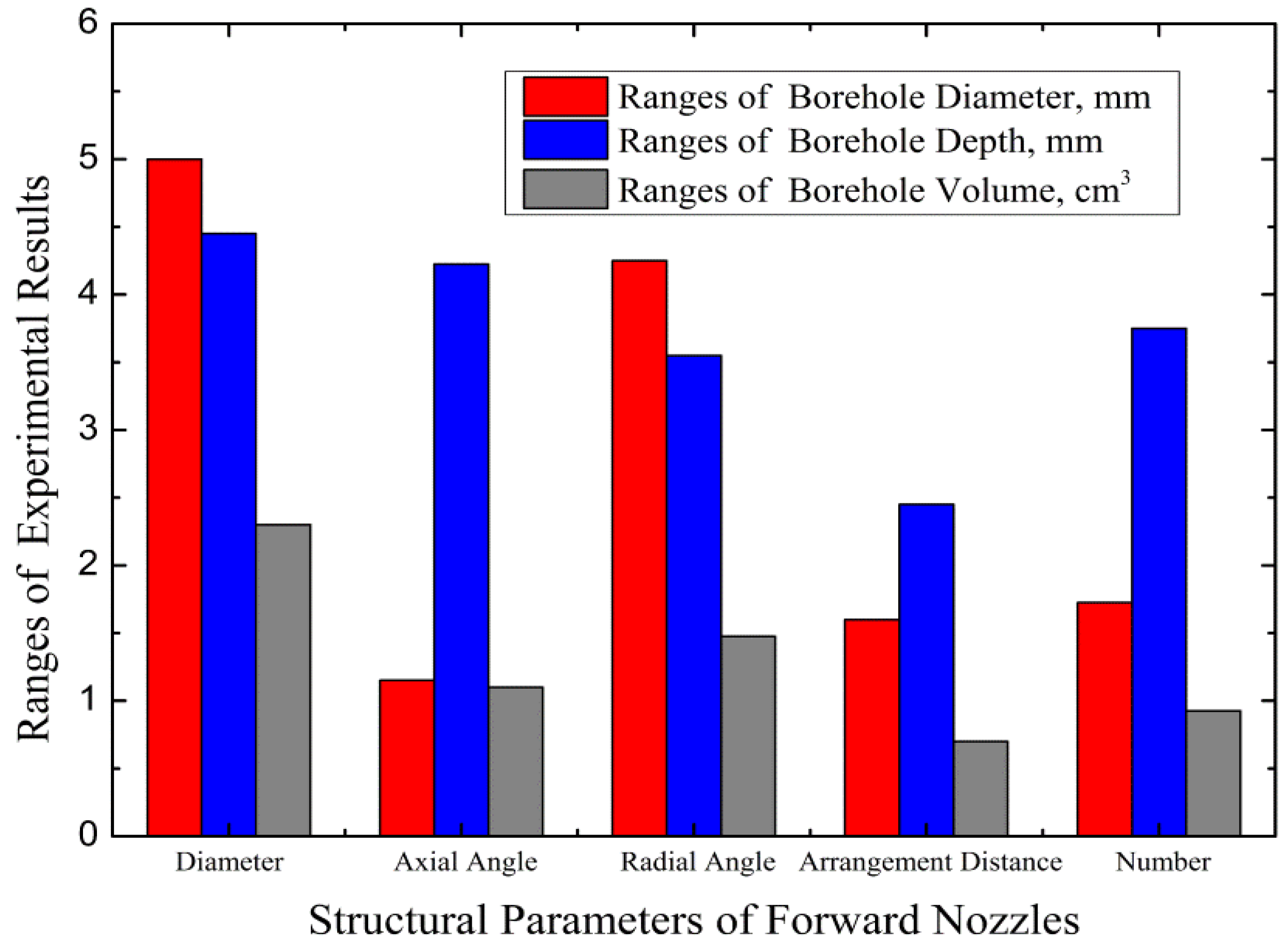
In the orthogonal experiments, the ranges of different factors are usually ranked in magnitude order. This order is known as the significant sequence. If the range of some factor is maximum, this means that change degree of the corresponding experiment results is greatest when the level values vary. Therefore, the greater the range value, the more significantly the corresponding factor affects the experimental result. The highest range value is the main factor: Figure 8 shows the analysis of ranges for the experimental results for an inlet jet pressure of 25 MPa. The significant sequence affecting borehole depth is the diameter, the axial angle, the number of nozzles, the radial angle, and the arrangement distance of forward nozzles, respectively. For borehole diameter, the sequence is the diameter, the radial angle, the number, the arrangement distance, and the axial angle. For borehole volume, the sequence is the diameter, the radial angle, the axial angle, the number, and the arrangement distance. The experiments show that the order of significant sequences is the same for all jet pressures used.
From the above significant sequences, it is obvious that the diameter of forward nozzles is the most important factor in the sequences, the factor that affects rock-breaking efficiency most significantly. The diameter of the nozzles directly determines the amount of rock-breaking energy. When the jet pressure drops and the other structural parameters are the same, the larger the nozzle diameter, the greater the rock-breaking jet flow and the greater the pulverization of the rock.
The effect of the radial angle of the forward nozzles on the diameter and volume of the borehole is in second place in the sequence and the radial angle’s influence on borehole depth is in fourth place. This fourth place range value is near the range value for the number of nozzles, which is in third place. The diameter of the borehole is the most important index because it determines whether the bit will be able to continue drilling the sub-borehole. Therefore, it is appropriate that the above analysis shows that the radial angle is in second place. The reason will be discussed in Section 4.2.2., below.
The effect of the axial angle on the depth, diameter, and volume of the borehole are in the second, fifth, and third places in those sequences, respectively. The axial angle’s influence on the borehole diameter is close to the influence of the number of nozzles and arrangement distance. The effect of the axial angle is more significant than the effect of the number of nozzles and the arrangement distance, therefore, the axial angle ranks in third place. The axial angle determines the magnitude of the three-dimensional jet velocity and energy distribution, thus affecting the shape of the volume of rock broken. However, it does not affect total rock-breaking energy transmitted and its influence on the synergistic effect of different jets is also weak. These are the reasons axial angle is in the third place.
The influence of the number of nozzles on the depth, diameter, and volume of the borehole is more significant than the arrangement distance, although the differences between their range values are small except for the influence on depth of borehole. Therefore, the significant sequence of number of nozzles and arrangement distance of forward nozzles are in the fourth and fifth places, respectively. The number of nozzles determines the number of rock-breaking jets and how uniformly rock is broken. This influences rock-breaking efficiency to some degree. However, the arrangement distance only determines the locations of the zones broken by the individual jets and this has little effect on the rock-breaking energy and jet velocity distribution, so its overall effect is least important.
It can be concluded from the analysis above that the influence of each parameter of the bit on rock-breaking efficiency is the same as the volume of rock broken. Obviously, the volume of rock removed can be used as a comprehensive index for evaluating the rock-breaking efficiency of the multi-nozzle bit.

4.2. Analysis of the Effect of Structural Parameters on Rock-Breaking Efficiency

The volume of rock broken and the diameter of the borehole are the important indexes for evaluating the efficiency of a multi-nozzle bit. Therefore, in order to analyze what controls rock-breaking efficiency, graphs were generated with borehole volume or borehole diameter on the y-axis and one parameter of the forward nozzles on the x-axis.

4.2.1. Effect of Forward Nozzle Diameter on Rocking-Breaking Efficiency

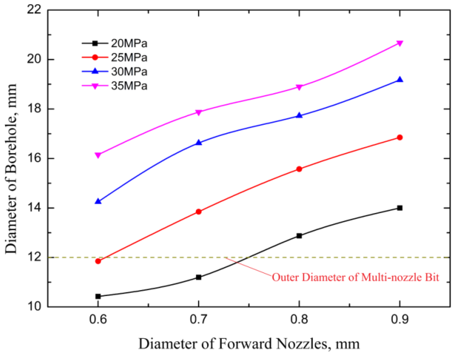
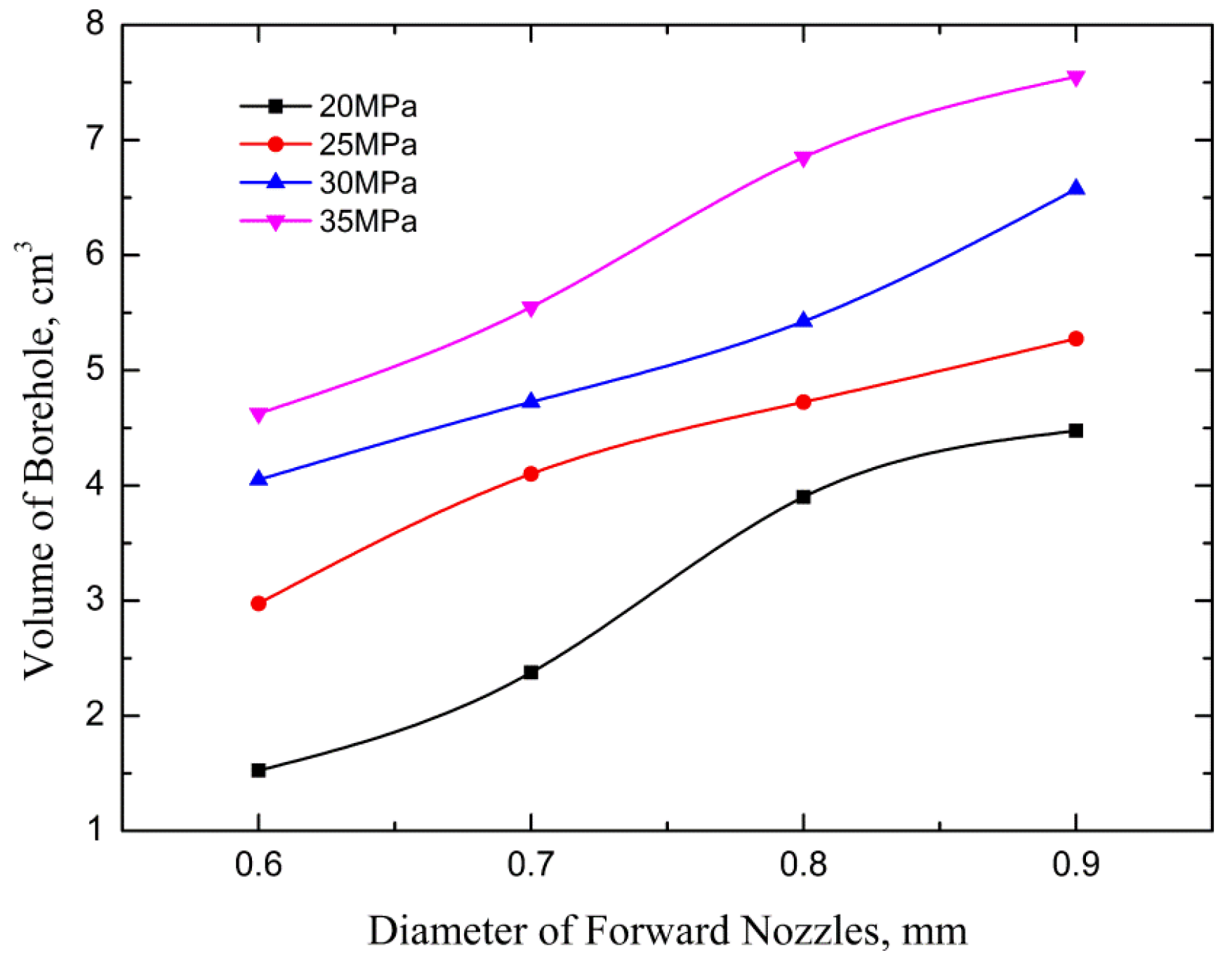
The diameter of the forward nozzles determines the amount of rock-breaking energy delivered to the rock face. Therefore, it is necessary to study the influence of nozzle diameter on rock-breaking efficiency. As shown in Figure 9 and Figure 10, the diameter and volume of the borehole increase as the diameter of the forward nozzles increase.
When the diameter of forward nozzles is too small and the jet pressure low, the borehole diameter is less than the outer diameter of the bit (12 mm). This will cause self-drilling to cease. When the jet diameter is small, the energy output from a single jet is weak and relatively restricted and the bit will not drill a large borehole easily. With an increased jet diameter, the jet flow increases so that the impact, tensile, and shear action of the jet are stronger and the rock-breaking ability is enhanced. However, according to the formula of pipeline pressure loss [28], the pressure loss is proportional to the square of the flow. Too large a jet diameter will make jet flow increase too much resulting in a huge pressure loss in the high-pressure hose. However, if the pump pressure and flow rate can meet the demand and the jet pressure surpasses the threshold pressure for rock fragmentation, increasing the diameter of forward nozzles will enhance the rock-breaking ability of a multi-nozzle bit.

4.2.2. Effect of Forward Nozzle Radial Angle on Rocking-Breaking Efficiency

A conventional multi-nozzle bit only inclines the forward nozzles with an axial angle [15,18,21]. Although the axial angle can ensure expansion of the area of broken rock, the synergistic rock-breaking effect of multiple jets is not realized. During self-drilling or erosion experiments with a fixed standoff distance, as the surface rock spalls, the distance between the multi-nozzle bit and the target rock is changing so that the locations of rock-breaking points are also changing. It is proposed that a radial angle for the nozzles be incorporated into the bit design to make full use of the synergy of multiple jets to break the rock. The benefits of this design are discussed below.
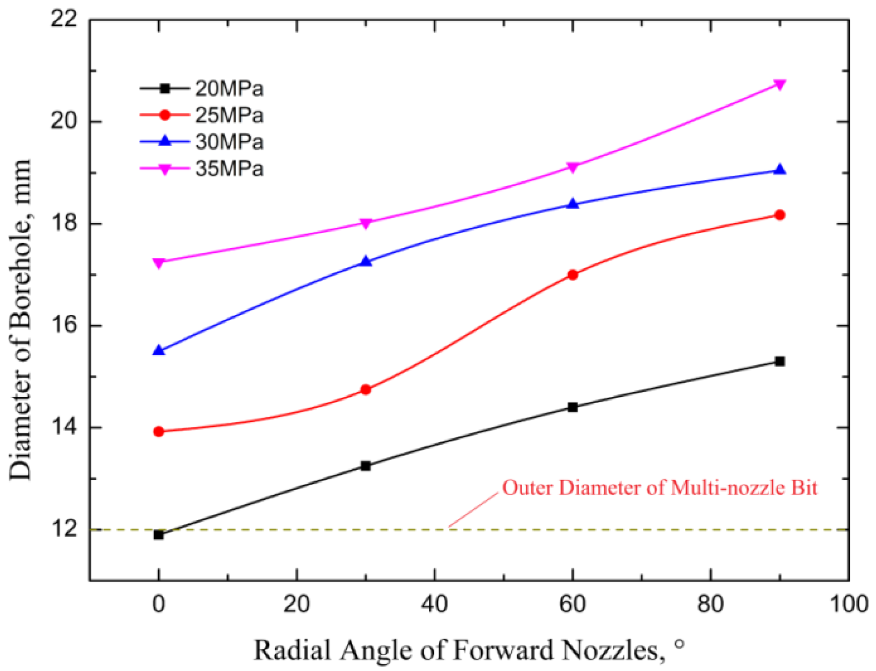
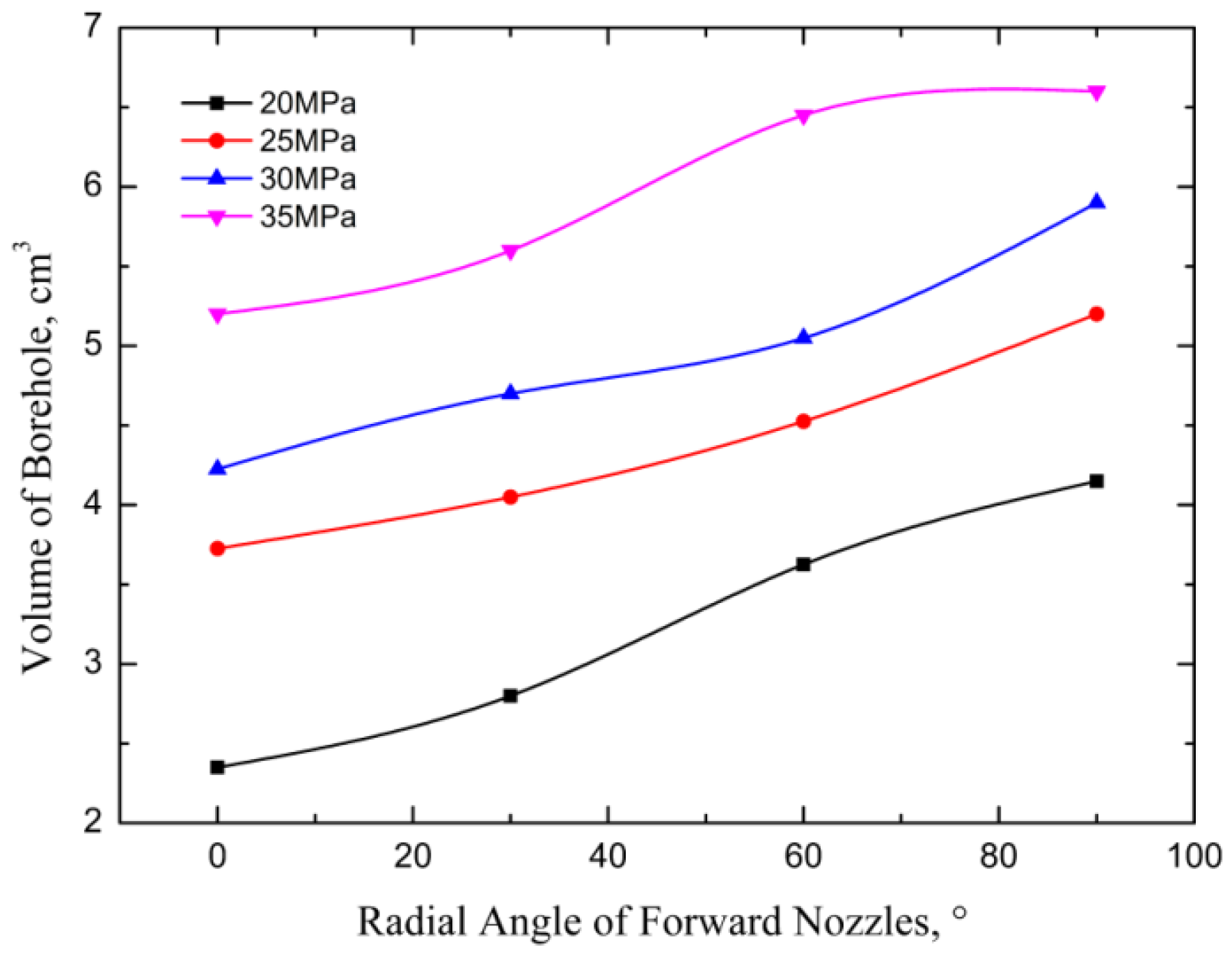
Figure 11 and Figure 12 show the benefit of including a radial angle for the forward nozzles in order to increase rock-breaking efficiency. With increasing radial angle, the diameter and the volume of the borehole increase significantly. The reason is that the positions of the rock-breaking points impacted by the jets change as the hole progresses. Figure 13 is a schematic diagram showing the changes in location of the rock-breaking points for a multi-nozzle bit with “4 + 1” forward nozzles. The black circles in the diagram represent the zones broken by the jets, assuming that the broken areas are the same for each point at different locations.
As shown in Figure 13, when the rock surface spalls, the distance between the jet and the rock face increases and the action points will gradually move outward along the radial and axial directions. When the radial angle is small (such as 30°), the radial deflection is so small that the borehole formed by synergistic effects among jets is small, thus resulting in a huge blind area (an area where the rock is not hit by any jets and therefore is not broken). With the radial angle increased (to, for example, 60°), the rock-breaking capacity of the multiple jets is enhanced. This results in a smaller blind area and the collaborating jets aid the formation of a connected, and larger diameter, borehole. When the radial angle is 90°, the rock-breaking zones of every jet overlap and the rock erosion zones are evenly distributed. This jet geometry forms a large and smooth borehole. These considerations are why the influence of the radial angle on rock-breaking efficiency was assigned the second place in the discussion in Section 4.1.

4.2.3. Effect of Forward Nozzle Axial Angle on Rocking-Breaking Efficiency

The axial angle of forward nozzles mainly determines the magnitude of the jet velocity in the axial, radial, and tangential directions. Thus, this angle affects the stress distribution in the rock and determines the mode in which the rock fails. Therefore, the effect of the axial angle on the rock-breaking efficiency should be investigated.
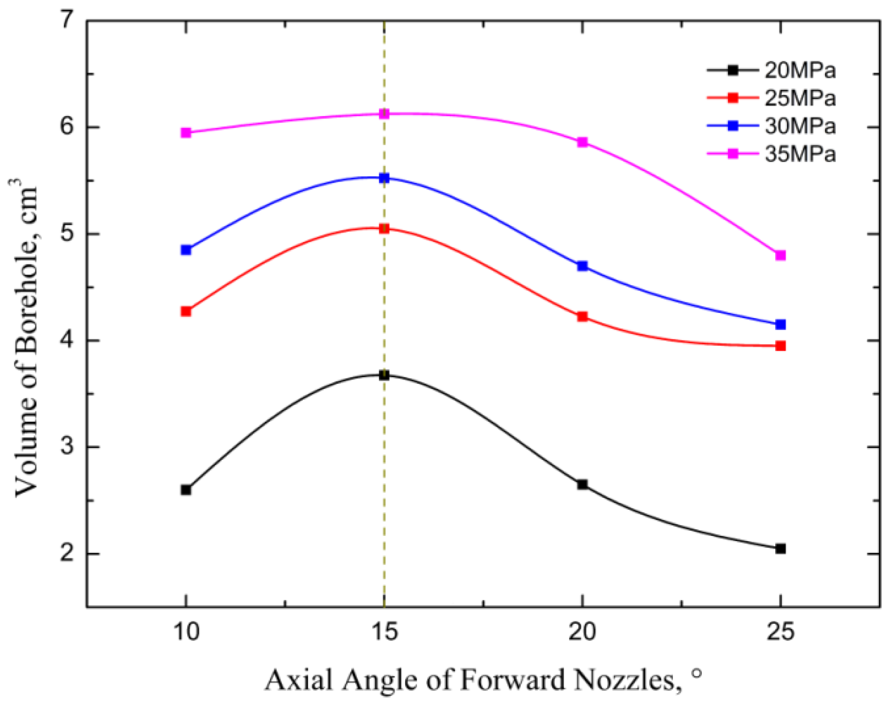
As shown in Figure 14, as the axial angle of the forward nozzles increases, the volume of the borehole first increases and then decreases. Solving Equations (8)–(10) shows that when the axial angle is small, the axial velocity component is dominant but the radial and tangential components of the jet velocity are weak. Therefore, the rock is mainly broken by impact damage and the diameter of the borehole is small. This means that it will be difficult for the jets to work together to make full use of the combined rock-breaking capacity of multiple jets. The radial velocity of the jet increases with increasing axial angle and increased velocity means that the rock will undergo shear failure resulting in more easily broken rock [29]. However, if the axial angle is too large, the jets are so dispersed and the collaboration of multiple jets is so small that the volume of rock broken decreases. In addition, the borehole (in the 3 min experiments) is shallow because the axial velocity is low. It is clear that there is an optimum axial angle for a multi-nozzle bit. Under the experimental conditions used for this paper, that angle is 15°.

4.2.4. Effect of the Number of Forward Nozzles on Rocking-Breaking Efficiency

If the diameter of the borehole is larger and the hole wall smoother, the bit will be able to drill forward and discharge rock or coal debris more easily. The number of forward nozzles determines both the number of rock-breaking jets and the synergistic effects among jets. These factors strongly influence the shape of the borehole and contribute to rock-breaking efficiency. Therefore, it is necessary to study how many forward nozzles are required to drill sub-boreholes that are suitably smooth with high efficiency for a specific jet pressures.
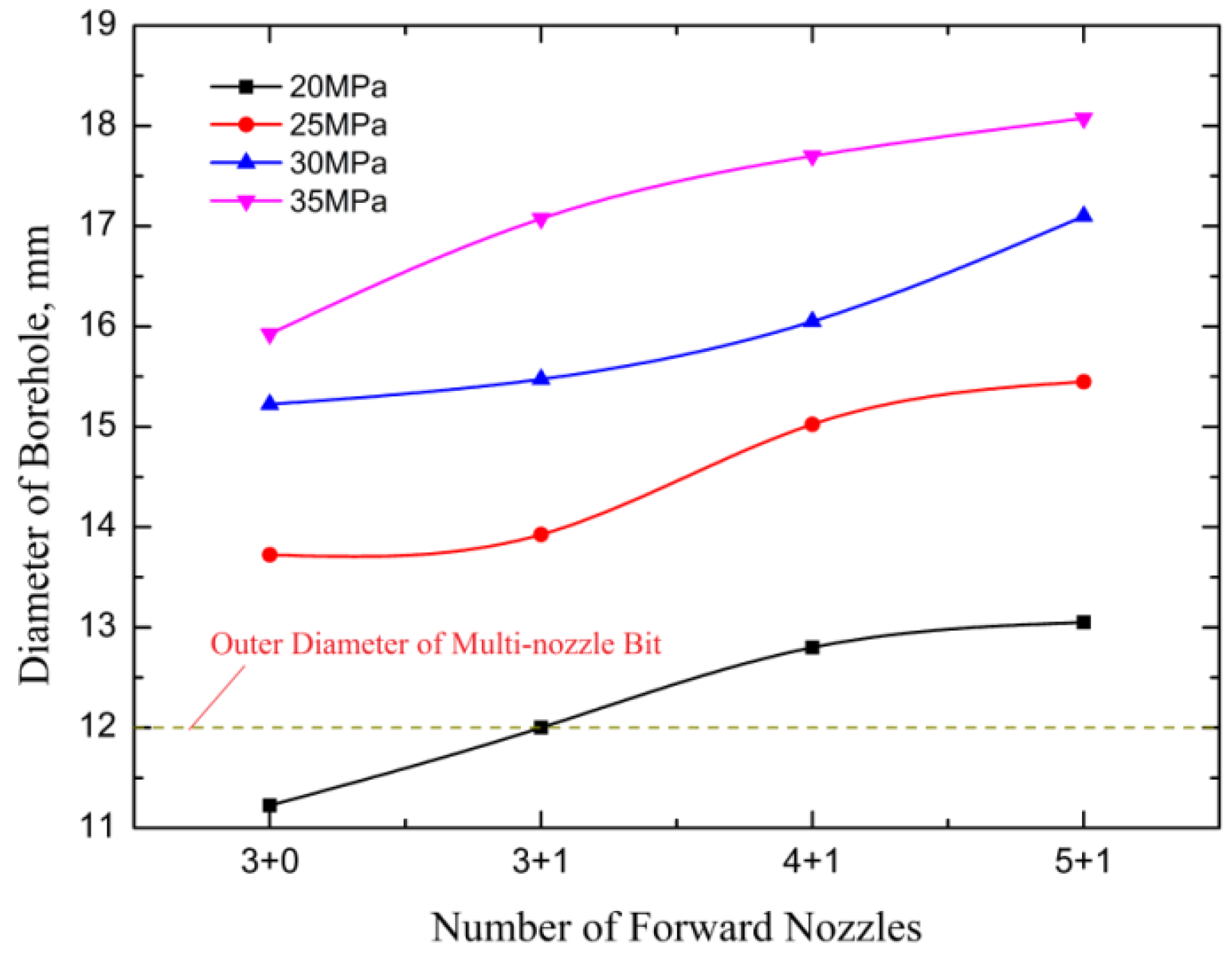
As shown in Figure 15, as the number of nozzles increases, the diameter of the borehole first increases significantly and then increases more moderately. When there are few nozzles and the jet pressure is low, the borehole is smaller than the outer diameter of the multi-nozzle bit and self-drilling will stop.
Because the small number of nozzles will produce a very jagged hole (Figure 16a), the narrowest part of the borehole is extremely small. With a larger number of nozzles, the number of rock-breaking jets is increased and the distribution of jet energy is more uniform. This breaks more rock and makes a better hole. However, when the number of nozzles gets too high, the jets start to interfere with each other and the jet energy is used less efficiently. This results in decreasing benefits as additional nozzles are added. An additional consideration is that increasing the number of forward nozzles leads to an increase in jet flow and this requires an increase in input pressure. Increasing the pressure will inevitably lead to more pressure loss in the hose. Figure 16 shows the shapes of the initial boreholes formed by “3 + 1” and “5 + 1” multi-nozzle bits. As can be seen in the figure, more forward nozzles make better boreholes. For the “5 + 1” bit, the borehole is nearly circular. Therefore considering all the constraints mentioned above, when designing a multi-nozzle bit, the number of forward nozzles should be minimized to ensure that a large, round borehole is produced but this must be done without sacrificing rock-breaking capability.

4.2.5. Effect of Forward Nozzle Arrangement Distance on Rocking-Breaking Efficiency

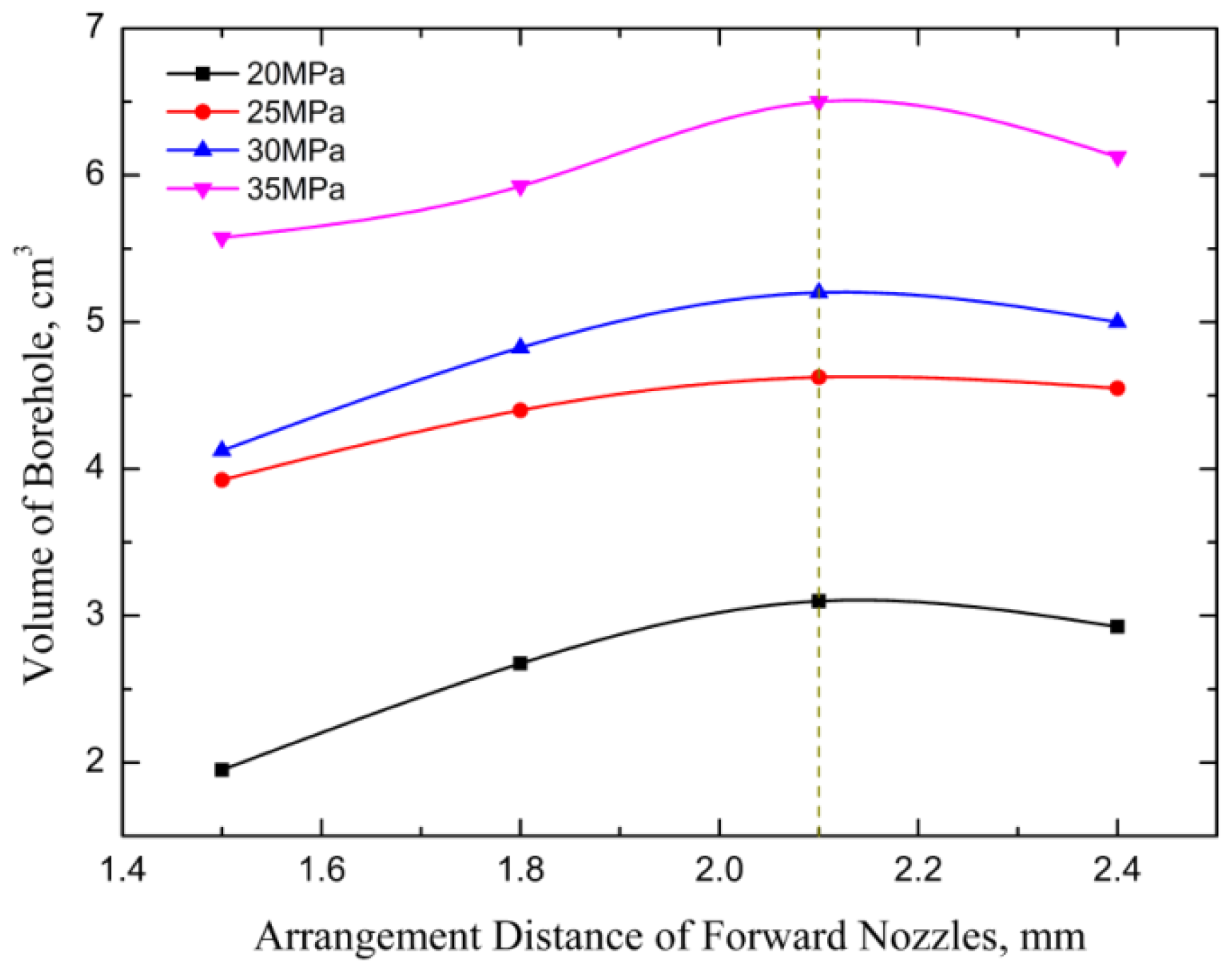
The arrangement distance of the forward nozzles determines the positions of the jet outlets and the degree of jet dispersion. These affect the positions of the rock-breaking points and greatly influence borehole diameter and volume. As shown in Figure 17, the volume of rock broken first increases and then decreases slightly as the arrangement distance of the forward nozzles increases. There is an optimal arrangement distance and under the experimental conditions used for this paper, that distance is 2.1 mm. Departures from optimum rock-breaking may be caused by the presence or absence of nozzle jet interactions. When the arrangement distance is small, the jets from the multi-nozzle bit will interfere with each other and this reduces rock-breaking efficiency and forms a small diameter borehole. With a small nozzle spacing, the bit fails to make full use of the collaborative rock-breaking capacity of the multiple jets. However, if the arrangement distance is too large, the different jets will break rock alone so that the zones of broken rock produced by each jet are separated and the individual damage zones are not connected. At the optimal arrangement distance, neither of these unfavorable conditions occurs.

4.3. Regression Analysis of Experimental Results

On the base of experimental results obtained in Table 2, the regression models were built for volume of borehole, as a comprehensive index for evaluating the rock-breaking efficiency of a multi-nozzle bit, with respect to five structural parameters (where n = nl + nc). Stepwise analysis of multivariate two-degree polynomial was carried out to analyze the volume of borehole. When the jet pressure was 25 MPa, through the R language, the regression equation can be obtained as follows:
V = 0.616309 + 0.043213 β 0.396698 n + 8.67 × 10 - 5 β 2 + 1.028957 d 0 L + 1.293869 d 0 n 0.033511 d 0 α + 0.063155 L n 0.007573 β n
where p-value of regression model is 0.0005104, which means that the significant degree is high and regression equation is valid; correlation coefficient R2 is 0.9286, which indicates that the overall effect of polynomial regression is nice.
It can be known through Equation (15) that the effect of the diameter of forward nozzles on volume of borehole is most significant. Secondary factor is radial angle, which agrees with the above range analysis. Moreover, the interactions among five factors (the diameter, number, axial angle, radial angle, and arrangement distance of the nozzles) appear and are identified. It means that the interactions should be considered in optimization of the structural parameters for a multi-nozzles bit. When the volume of borehole reaches the maximum (jet pressure is 25 MPa), five factors are d0 = 0.9 mm, α = 10°, β = 90°, L = 2.4 mm, n = 5 + 1, respectively. There is a slight difference between the computed values and conclusions derived by the trend graphs. This is why the interactions among different factors are considered for computed results from regression model. As for regression Equation (15), we can see that the bigger diameter and the more number of nozzles, the larger volume of borehole. However, under different working conditions, these factors should be considered comprehensively, such as pipeline pressure loss and self-propelling force, etc.

5. Conclusions

Tree-type drilling is a new technology for utilizing high-pressure water jets to drill radial tree-type boreholes in coal seams. The tree-type boreholes provide better gas drainage in terms of both quantity of gas removed and area drained than that provided by single gas drainage boreholes. As a critical component of this technology, the multi-nozzle bit is highly efficient for drilling this type of borehole. First, the relationships between the forward nozzles in a multi-nozzle bit and nozzle jet velocities and the diameter of the borehole are described. Then the physical parameters (the diameter, number, axial angle, radial angle, and arrangement distance of the nozzles) that affect the rock-breaking properties of a multi-nozzle bit are established. Subsequently, by conducting drilling experiments, how the parameters of the forward nozzles influence the diameter, depth, and volume of boreholes are determined and analyzed. The comprehensive significant sequences that affect rock-breaking efficiency are the diameter, the radial angle, the axial angle, the number of nozzles, and the arrangement distance of the forward nozzles. Finally, the effects of the parameters on rock-breaking efficiency of multi-nozzle bits are studied indirectly through orthogonal analysis of the experimental results, and regression analysis for experimental results was carried out through R language. Forward nozzles with the proper large diameter can improve the rock-breaking ability of multi-nozzle bits when the flow rate and jet pressure loss in the hose are not excessive. There is an optimal radial angle, axial angle, and arrangement distance for the forward nozzles in a multi-nozzle bit. Under the experimental conditions used here, the optimal radial angle is 90°, the optimal axial angle 15°, and the optimal arrangement distance 2.1 mm. The larger the number of forward nozzles, the more rounded the shape of the borehole. These conclusions will be helpful for optimizing the design of multi-nozzle bits for many applications including radial RJD and bent pipe cleaning.

Acknowledgments

This study was jointly funded by the National Natural Science Foundation of China (Nos. 51374258 and 51504046), and the Program for Changjiang Scholars and Innovative Research Team in University of China (No. IRT13043).

Author Contributions

Yiyu Lu, Songqiang Xiao, Zhaolong Ge and Zhe Zhou all contributed to conceiving and designing the experiments, analyzing the data, and writing the paper. Kai Deng performed experiments.

Conflicts of Interest

The authors declare no conflict of interest.

References

  1. Sun, M.Y. CBM, a nascent new energy. Sci. Technol. Rev. 1996, 8, 59–61. [Google Scholar]
  2. Hu, G.Z.; Huang, X.; Xu, J.L.; Qin, W.; Wang, H.T. A co-extraction technology of coal and CBM based on the law of gas advanced relieving pressure of in-seam coalface. Disaster Adv. 2012, 5, 1351–1356. [Google Scholar]
  3. Dai, J.X.; Ni, Y.Y.; Wu, X.Q. Tight gas in China and its significance in exploration and exploitation. Pet. Explo. Dev. 2012, 39, 277–284. [Google Scholar] [CrossRef]
  4. Bibler, C.J.; Marshall, J.S.; Pilcher, R.C. Status of worldwide coal mine methane emissions and use. Int. J. Coal Geol. 1998, 35, 283–310. [Google Scholar] [CrossRef]
  5. Hu, G.Z.; Xu, J.L.; Zhang, F.X.; Zhao, C.C.; Qin, W.; Zhu, Y.R. Coal and coalbed methane co-extraction technology based on the ground movement in the Yangquan coalfield, China. Energies 2015, 8, 6881–6897. [Google Scholar] [CrossRef]
  6. Lin, B.Q.; Liu, T.; Zhou, Y.; Zhang, Z.; Yan, F.Z. Variation of methane adsorption property of coal after the treatment of hydraulic slotting and methane pre-drainage: A case study. J. Nat. Gas Sci. Eng. 2014, 20, 396–406. [Google Scholar]
  7. Qian, M.G.; Miao, X.X.; Xu, J.L. Resources and environment harmonics (green) mining and its technological system. J. Min. Saf. Eng. 2006, 23, 1–5. [Google Scholar]
  8. Noack, K. Control of gas emissions in underground coal mines. Int. J. Coal Geol. 1998, 35, 57–82. [Google Scholar] [CrossRef]
  9. Shen, B.H.; Liu, J.Z.; Zhang, H. The technical measures of gas control in China coal mines. J. China Coal Soc. 2007, 32, 673–679. [Google Scholar]
  10. Lu, T.K.; Yu, H.; Zhou, T.Y.; Mao, J.S.; Guo, B.H. Improvement of methane drainage in high gassy coal seam using waterjet technique. Int. J. Coal Geol. 2009, 79, 40–48. [Google Scholar] [CrossRef]
  11. Lu, Y.Y.; Liu, Y.; Li, X.H.; Kang, Y. A new method of drilling long boreholes in low permeability coal by improving its permeability. Int. J. Coal Geol. 2010, 84, 94–102. [Google Scholar] [CrossRef]
  12. Yuan, L.; Lin, B.; Yang, W. Research progress and development direction of gas control with mine hydraulic technology in China coal mine. Coal Sci. Technol. 2015, 43, 45–49. [Google Scholar]
  13. Wang, Y.F.; He, X.Q.; Wang, E.Y. Research progress and development tendency of the hydraulic technology for increasing the permeabilityof coal seams. J. China Coal Soc. 2014, 39, 1945–1955. [Google Scholar]
  14. Lu, Y.Y.; Zhou, Z.; Ge, Z.L.; Zhang, X.W.; Li, Q. Research on and design of a self-propelled nozzle for the tree-type drilling technique in underground coal mines. Energies 2015, 8, 14260–14271. [Google Scholar] [CrossRef]
  15. Ma, D.J.; Li, G.S.; Niu, J.L.; Liao, H.L.; Huang, Z.W. Experimental study on rock breaking and drilling laws by multi-hole jet bit. Fluid Mach. 2015, 43, 1–5. [Google Scholar]
  16. Buset, P.; Riiber, M.; Eek, A. Jet Drilling Tool: Cost-Effective Lateral Drilling Technology for Enhanced Oil Recovery. In Proceedings of the SPE/ICoTA Coiled Tubing Roundtable, Houston, TX, USA, 7–8 March 2001.
  17. Buckman, W.G., Sr. Method and Apparatus for Jet Drilling Drainholes from Wells. U.S. Patent 6,263,984 B1, 24 July 2001. [Google Scholar]
  18. Liao, H.L.; Niu, J.L.; Cheng, Y.X.; Huang, Z.W.; Ma, D.J. Experiment study on water jet breaking rock by multi-orifice nozzle. J. China Coal Soc. 2011, 36, 1858–1862. [Google Scholar]
  19. Ma, D.J.; Li, G.S.; Huang, Z.W.; Li, J.B.; Wang, J.L. Mechanism of a self-propelled multi-hole jet bit and influencing rules on its self-propelled force. Nat. Gas Indus. 2014, 34, 99–104. [Google Scholar]
  20. Di, F.; Li, G.S.; Huang, Z.W.; Song, X.Z.; Chi, H.P. Capability analysis of self-feeding multi-nozzle jet bit in radial horizontal drilling. China Pet Mach. 2014, 42, 7–11. [Google Scholar]
  21. Li, J.B.; Li, G.S.; Huang, Z.W.; Song, X.Z.; Yang, R.R.; Peng, K.W. The self-propelled force model of a multi-orifice nozzle for radial jet drilling. J. Nat Gas Sci. Eng. 2015, 24, 441–448. [Google Scholar] [CrossRef]
  22. Hu, K.; Peng, X.; Li, J.; Hu, B.W.; Ai, Z.J. Simulation based on the CFD of self-propulsion nozzle’s flow field. J. Southwest Pet. Univ. Sci. Technol. Ed. 2013, 35, 159–165. [Google Scholar]
  23. Liu, C.; Wu, Z.H.; Zhang, J.J. Fluid-structure interaction analysis of radial hole drilling jet nozzle in rock breaking. Oil Field Equip. 2015, 44, 10–14. [Google Scholar]
  24. Zhou, Y.X. The Experiment Design and Data Processing; Hubei Science and Technology Press: Wuhan, China, 2005; pp. 113–138. [Google Scholar]
  25. Chi, H.P.; Li, G.S.; Liao, H.L.; Huang, Z.W.; Song, X.Z.; Di, F.; Tang, G.W. Experimental research on optimum of jetting bit in radial drilling by hydra-jet. Fluid Mach. 2013, 41, 1–6. [Google Scholar]
  26. Ma, D.J.; Li, G.S.; Zhang, X.N.; Huang, Z.W. Experimental study on rock breaking by a combined round straight jet with a swirling jet nozzle. At. Sprays 2011, 21, 645–653. [Google Scholar] [CrossRef]
  27. Liao, H.L.; Li, G.S.; Niu, J.L.; Huang, Z.W. Integrating straight & swirling jets bit design and its rock breaking characteristics for radial horizontal hole drilling. J. China Coal Soc. 2013, 38, 424–429. [Google Scholar]
  28. Labus, T.J. Fluid Jet Technology: Fundamentals and Application; Water Jet Technology Association: St. Louis, MO, USA, 1995. [Google Scholar]
  29. Chen, T.G.; Guan, Z.C. Theory and Technology of Drilling Engineering; China University of Petroleum Press: Dongying, China, 2006; pp. 148–154. [Google Scholar]
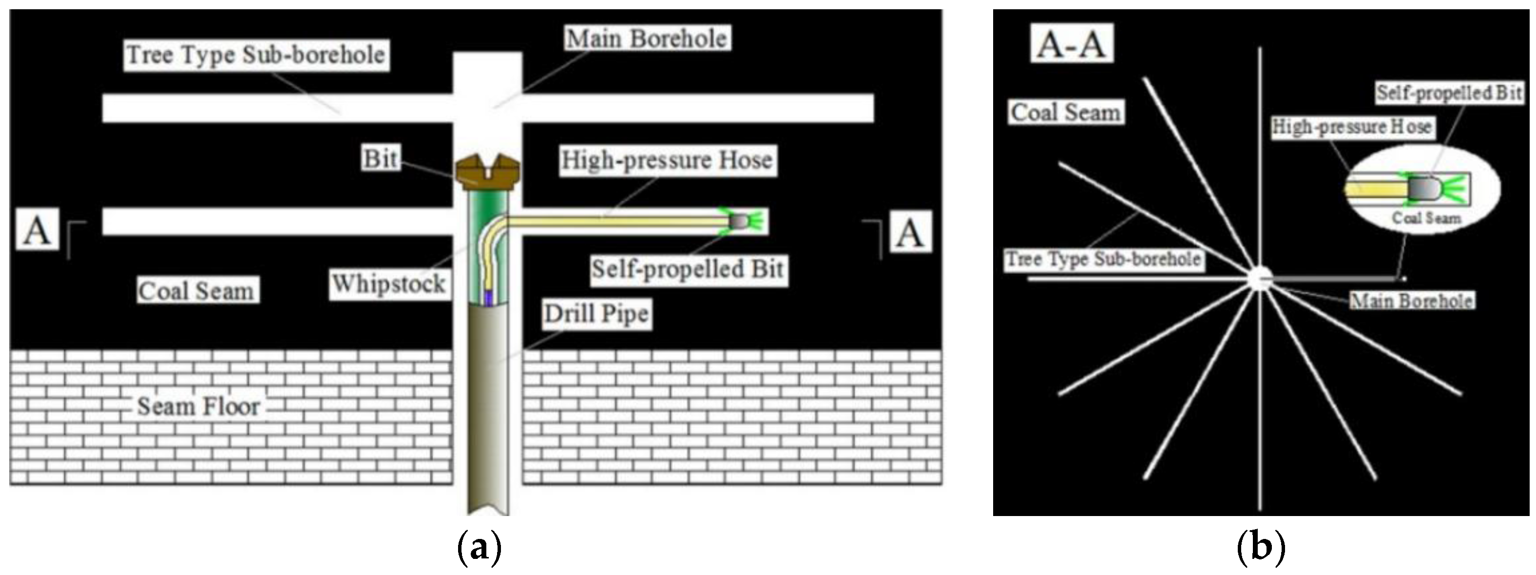
Figure 1. Schematic diagram of tree-type boreholes: (a) panel-cross section; and (b) panel-plan view. The main borehole would be approximately 100–130 mm in diameter, while diameter of the tree-type sub-borehole drilled by bit in coal mines can reach 30–50 mm and the sub-borehole lengths can be 10–20 m.
Energies 09 00249 g001
Figure 2. Structural diagrams showing a longitudinal section: (a) an axial section; and (b) a multi-nozzle bit. The bits used in this study are 12 mm in outside diameter. (D1 and D2 are the inside and outside diameter of the bit, respectively. P is the inlet pressure of the bit. v1, v2 and v3 are the jet velocity of center, lateral and backward nozzles of the bit, respectively.)
Energies 09 00249 g002
Figure 3. Structural diagram showing the forward nozzles: (a) a multi-nozzle bit; and (b) a diagram showing the relationship between their structural parameters and jet velocity.
Energies 09 00249 g003
Figure 4. Schematic diagram: (left) a multi-nozzle bit breaking rock; and (right) a diagram showing the internal geometry of the same bit.
Energies 09 00249 g004
Figure 5. Photograph showing the 16 different multi-nozzle bits used in the experiments.
Energies 09 00249 g005
Figure 6. Schematic of the rock breaking test system.
Energies 09 00249 g006
Figure 7. Photograph of the rock breaking test system.
Energies 09 00249 g007
Figure 8. Range analysis for the experiments run under a jet pressure of 25 MPa.
Energies 09 00249 g008
Figure 9. Graph of diameter of forward nozzles vs. diameter of the borehole.
Energies 09 00249 g009
Figure 10. Graph of diameter of forward nozzles vs. the volume of borehole.
Energies 09 00249 g010
Figure 11. Graph of the radial angle of the forward nozzles vs. the diameter of the borehole.
Energies 09 00249 g011
Figure 12. Graph of the radial angle of the forward nozzles vs. the volume of borehole.
Energies 09 00249 g012
Figure 13. Schematic diagram showing how the positions of the rock-breaking points move as the rock spalls away from the multi-nozzle bit. Increasing the radial angle reduces the “blind zones”, the areas not impacted by the jet from any nozzle.
Energies 09 00249 g013
Figure 14. Graph of the axial angle of the forward nozzles vs. borehole volume.
Energies 09 00249 g014
Figure 15. Graph of the number of forward nozzles vs. the diameter of borehole.
Energies 09 00249 g015
Figure 16. Photographs of the shapes of partial boreholes drilled in concrete blocks: (a) “3 + 1”; and (b) “5 + 1” multi-nozzle bits. “3 + 1” and “5 + 1” mean the bit has three or five lateral nozzles and one center nozzle. The scales are marked in centimeters.
Energies 09 00249 g016
Figure 17. Graph of the arrangement distance of forward nozzles vs. the volume of the borehole.
Energies 09 00249 g017
Table 1. Factors and corresponding level values for the multi-nozzle bits used in the drilling experiments.
LevelsFactors
d0 1/mmα 2/(°)β 3/(°)L 4/mmnl + nc 5
10.61001.53 + 0
20.715301.83 + 1
30.820602.14 + 1
40.925902.45 + 1
1 d0, 2 α, 3 β, 4 L are the diameter of single nozzle of forward nozzles, the axial angle, the radial angle and the arrangement distance of lateral nozzles, respectively. 5 nl + nc means nl lateral nozzles and nc center nozzles. For example, 4 + 1 means four lateral nozzles and one center nozzle whereas 3 + 0 means three lateral nozzles with no center nozzle. For our experiments, nc is either zero or one.
Table 2. Structural parameters of forward nozzles in the multi-nozzle bits used in the experiments and the corresponding response values for experimental results under the jet pressure drop of 25 MPa.
No.Structural Parameters of Forward NozzlesResponse Values (25 MPa)
d0/mmα/(°)β/(°)L/mmnl + nch/mmD/mmV/cm3
1#0.61001.53 + 024.09.01.3
2#0.615301.83 + 128.010.93.1
3#0.620602.14 + 131.213.53.5
4#0.625902.45 + 129.014.04.0
5#0.710302.15 + 136.514.84.4
6#0.71502.44 + 132.314.44.6
7#0.720901.53 + 131.012.64.05
8#0.725601.83 + 028.013.63.35
9#0.810602.43 + 134.815.64.7
10#0.815902.13 + 033.515.06.0
11#0.82001.85 + 131.015.74.4
12#0.825301.54 + 129.416.03.8
13#0.910901.84 + 136.016.26.3
14#0.915601.55 + 135.017.36.1
15#0.920302.43 + 031.017.34.5
16#0.92502.13 + 128.016.64.2