
Progress in Heat Pump Air Conditioning Systems for Electric Vehicles—A Review

1
School of Mechanical and Automotive Engineering, South China University of Technology, Guangzhou 510641, China
2
Department of Mechanical and Electrical Engineering, Shunde Polytechnic, Foshan 528333, China
*
Author to whom correspondence should be addressed.
Energies 2016, 9(4), 240; https://doi.org/10.3390/en9040240
Submission received: 24 October 2015
/
Revised: 3 March 2016
/
Accepted: 17 March 2016
/
Published: 25 March 2016
Abstract
:Electric vehicles have become increasingly popular in recent years due to our limited natural resources. As a result, interest in climate control systems for electric vehicles is rising rapidly. According to a variety of research sources, the heat pump air conditioning system seems to be a potential climate control system for electric vehicles. In this paper, an extensive literature review has been performed on the progress in heat pump air conditioning systems for electric vehicles. First, a review of applications of alternative environmentally friendly refrigerants in electric vehicles is introduced. This is followed by a review of other advanced technologies, such as the inverter technology, innovative components and the system structure of the heat pump air conditioning system for electric vehicles. Lastly, recent developments in multiple source heat pump systems are presented. The use of these advanced technologies can provide not only sufficient refrigerating capacity for the electric vehicle, but also higher climate control system efficiency. We believe that ideal practical air conditioning for electric vehicles can be attained in the near future as the mentioned technical problems are gradually resolved.
1. Introduction
Due to pollution reduction and greenhouse gas emission reduction policies, fully electric vehicles (EVs) are being strongly promoted. In both EVs and internal combustion engine vehicles, a comfortable cabin environment is essential for passengers. However, in consideration of the absence of heat from the engine coolant in EVs, an innovative air conditioning (AC) system design must be provided. In recent years, solutions for the AC system in fully EVs have been studied extensively.
Some authors have presented the thermoelectric AC, whereby the vehicle cabin can be cooled and heated by thermoelectric modules, which have the advantage of having no moving parts, no noise, long life, small size and precise temperature control [1,2], but this technology has not been accepted due to poor efficiency. Currently, it is used only in seat heating and cooling in some luxury cars. In addition, this technology is applied to short-distance small EVs in view of limited resources and the low figure of merit of thermoelectric materials [3].
The simplest solution is to use an electric compressor instead of a mechanical compressor for cooling, meanwhile a positive temperature coefficient (PTC) heater is adapted to provide heating in place of the engine coolant heater core [4,5,6]. A 42 V electric AC system was proposed. The system consisted of a compressor, a blower, an integrated PTC heater, an inverter, pipes and some heat exchangers [5]. The cabin temperature would initially decline quickly and then change more consistently. The results showed the 42 V electric AC system could maintain a stable and comfortable interior environment under hot weather conditions. Moreover, it could achieve a relatively better thermal environment than the AC system used in conventional vehicles under very cold weather conditions. Although the PTC heater could provide sufficient heat energy to warm up the cabin, its energy was derived from battery electricity. It resulted in 24% losses of the driving range for fully EVs due to the low energy efficiency of PTC heaters [7]. A fuel fired heater was another option proposed for heating without electricity consumption, but it did not meet environmental demands.
Much research has focused on the heat pump AC system. It is based on the vapor compression cycle, which provides both cooling and heating capacity by adopting a 4-way valve that reverses the direction of refrigerant flow. Lee [8] declared that the power consumption of a heat pump system was about one third that of the electric PTC heating system for the same heating capacity. Moreover, the coefficient of performance (COP) of a heat pump AC system is larger than 1, so the heat pump AC system seems to be a more reasonable solution than other climate control systems proposed for EVs [9].
Various studies have been performed to enhance the heat pump AC system efficiency, especially the heating performance when faced with low outdoor temperatures. Besides the single air source heat pump AC system, multiple source heat pump AC systems have been developed for EVs. These systems can supply sufficient cooling or heating capacity while minimizing the influence of the AC system on driving ranges.
It is the intent of this paper to review the most recent progress concerning heat pump AC technologies for EVs. This review is broadly divided into two key categories and will be systematically organized. First, single source heat pump AC systems for EV applications are introduced. In this section, several advanced technologies and strategies concerning single air source heat pump AC systems are comprehensively reviewed. Second, multiple source heat pump AC systems are analyzed. These systems are applied for all possible heat sources in EVs to enhance the heating capacity under very low outdoor temperature conditions, as well as to achieve high energy efficiency. Finally, conclusions are drawn based on the various reviews and analyses.
2. Single Source Heat Pump AC Systems
Considering its convenient replacement, low cost and easy maintenance, the single source heat pump AC system is still dominant in EVs, especially in mild climate areas. However, the heat pump AC system, which only involves the necessary modifications based on conventional vehicle AC systems, has low system efficiency [10]. Therefore many scholars have presented innovative technologies in various aspects.
2.1. Alternative Refrigerants
At present, the refrigerant R134a, which has a global warming potential (GWP) of 1300, is still dominant in automotive AC systems, but for future environmental considerations, the Kyoto and Montreal protocols have banned or limited the use of chemical refrigerants [11]. Similarly, the European Union has passed regulations to restrict the use of refrigerants with a GWP higher than 150 in mobile AC systems [12]. A directive for the gradual phase-out of high GWP refrigerants in mobile AC systems was ratified in 2007 and went into effect at the beginning of 2008 [13]. In light of this situation, automotive AC systems using other potential substitute refrigerants have been studied [14]. CO2 is one of the most studied options since it has adequate thermophysical properties with no ozone depletion potential (ODP) and a GWP = 1 [15,16]. As a result, more and more authors are devoted to investigating automotive AC systems using CO2 as a refrigerant. Prototype CO2 automotive AC systems were presented in [17,18]. They concluded that, in the heat pump mode, high capacity and COP can also be achieved at low ambient temperature and with high air supply temperature to the passenger compartment [19]. Furthermore, the system performance was equal or superior to that of the current R134a system [20]. The cooling COP ratio to R134a system was 1, while the heating/dehumidifying COP ratio was 1.31. Kim et al. [21] studied the effects of operating parameters on the performance of a CO2 AC system for vehicles with various operating conditions, which include different gas cooler inlet pressures, compressor speeds and frontal air temperatures/flow rates passing through the evaporator and the gas cooler. They also proposed an algorithm for optimum high pressure control for the transcritical CO2 cycle to achieve a maximum COP.
Although CO2 AC systems have special benefits, they have some disadvantages, such as low critical temperature and high operating pressure [22]. Other problems in defrosting of exterior heat exchangers and performance deterioration under cold ambient temperature conditions exist in CO2 automotive heat pump systems as well as R134a heat pump systems. By re-arranging the radiator and outdoor heat exchangers of the CO2 heat pump system in electric cars, the heating capacity and COP were increased by 54% and 22%, respectively [23]. To enhance cooling performance, Lee et al. [24] presented an electrical AC system with CO2 that used an inverter-driven compressor. The cooling capacity and COP of this tested system were increased by 36.8% up to 6.4 kW and by 30.3% up to 2.5 kW, respectively. Ma et al. [25] conducted a thorough review of the CO2 heat pump and refrigeration cycle. They concluded that some modifications, such as using an internal heat exchanger, two-stage compression, and expansion work recovery as well as enhancing heat transfer, could improve the CO2 transcritical cycle performance to a level similar to that of a conventional heat pump system.
In addition to using CO2, other possible refrigerants in the heat pump AC system include R1234yf, R152a, R290, R245fa and water [26,27,28,29]. The performance of the R1234yf “drop-in” automotive AC system was analyzed and compared with that of systems with CO2 and R32 by experimentation and simulation [30]. The COP and capacity of R1234yf system were up to 2.7% and 4.0% lower than those of R134a system, respectively, while the compressor discharge temperature and amount of refrigerant charge were 6.5 °C and 10% lower than those of R134a system [31]. Consequently, the R1234yf “drop-in” AC system was the most feasible candidate for automobiles from the standpoint of system performance and operating conditions. However, more work must be completed before the R1234yf system can be widely accepted in EVs [31,32,33]. Ghodbane [34,35] presented the secondary loop system using R152a as the working fluid in mobile climate control systems. This system showed a very good cooling and heating performance, but had a slower response to load changes, complex system connections and a high cost.
2.2. Application of Inverter Technology
Frequency variation technology, a common way to save energy, is also widely used in AC systems. An R134a automotive AC system capable of operating as an air-to-air heat pump is described in Figure 1 [36].
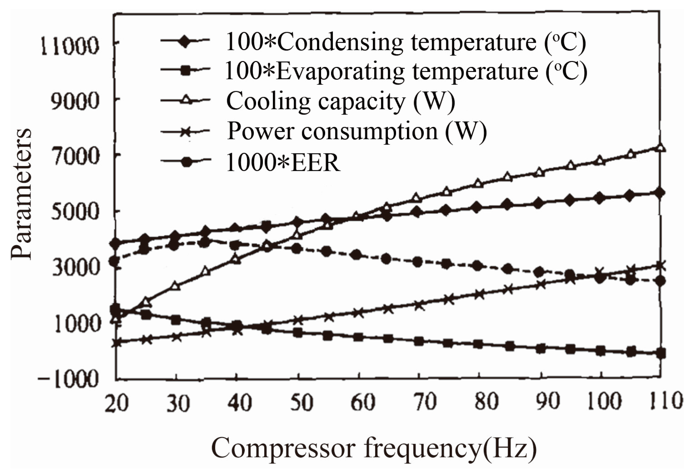
This system was tested by varying the compressor speed. The conclusions showed that both the heating and the cooling capacities of the system increased with the rise of compressor speed, whereas the COPs in both cases decreased. Jabardo et al. [37] also reported an automotive AC system equipped with a variable capacity compressor run by an electric motor controlled by a frequency converter. The impact on system performance of operational parameters such as compressor speed, return air in the evaporator and condensing air temperatures, was experimentally evaluated and simulated by means of the developed model. To better develop the inverter AC system, all factors which influence the performance of the variable frequency AC system have been discussed in [38]. Effects of compressor frequency on the performance and parameters are shown in Figure 2. At a fixed ambient temperature and heat transfer area of heat exchangers, the cooling capacity and power consumption increased as the compressor frequency increased. In contract, the energy efficiency ratio (EER) initially increased but subsequently decreased, so the compressor frequency should be increased in order to improve the cooling capacity, while it should be decreased in order to reduce power consumption. These results are very useful for optimizing the design, and automatically controlling and diagnosing exceptions in the operation of variable frequency AC systems.
In addition to variable-speed compressors, adjusting the fan speed can lead to further performance and efficiency improvements. Lee et al. [39] focused on the effect of outdoor coil fan speed on the performance variation of the heat pump system adopting the hot gas bypass method. The integrated heating capacity with hot gas bypass was highest at 60% (780 rpm) fan speed. This value was 4.4% higher than that of the constant speed fan. On the other hand, the averaged COP of the heat pump in this case was higher by 2.8% than the constant speed fan. As mentioned in [40], three frequency converters were equipped to control the speeds of the compressor, the evaporator fans and the condenser fans, respectively. The analysis showed that the three speeds could be adjusted simultaneously according to both actual working conditions and operation mode so that the AC system could operate in an optimum state, but in practical applications only one fan speed and compressor speed need to be modulated in real-time, considering hardware costs and system complexity.
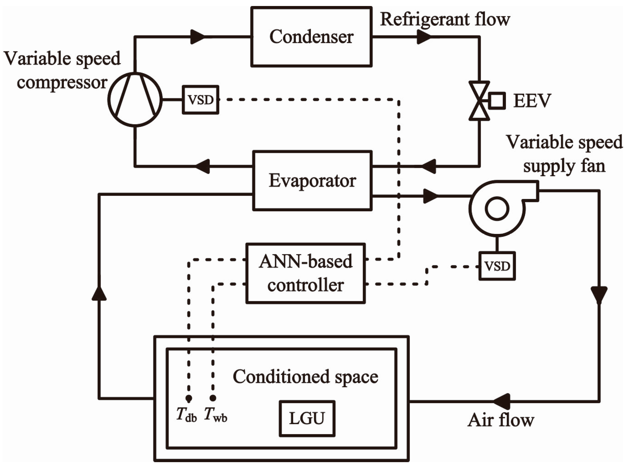
Advanced control algorithms have also been studied by many authors. Yeh et al. [41] proposed two control algorithms. The first algorithm, which modulated the outdoor fan speed, could enhance the steady-state power efficiency. The second algorithm, which added one more degree of freedom to control by modulating the indoor fan speed, could improve the transient response. The performance of the AC system could be improved if both algorithms were simultaneously implemented in the way that the second algorithm was responsible for the control action during the startup/transient phase of operation, and the first algorithm took over at steady state. Shi et al. [42] described three control algorithms for the inverter AC system: the matrix control, the system-relative commands control and the fuzzy control. Moreover, to realize comfort and system energy efficiency, they explained the mechanism to regulate the running speed of the compressor, indoor and outdoor fans, and the opening of the expansion valve. As shown in Figure 3, an artificial neural network-based controller was developed to simultaneously control the indoor air temperature and humidity by varying the compressor speed and supply fan speed [43]. The controllability tests including command following test and disturbance rejection test showed that the artificial neural network-based was able to track changes in setpoints and to resist disturbances with an adequate control accuracy. Although these control algorithms are mainly applied in building AC systems, in theory, they are also suitable for the AC systems of EVs.
2.3. Novel Components
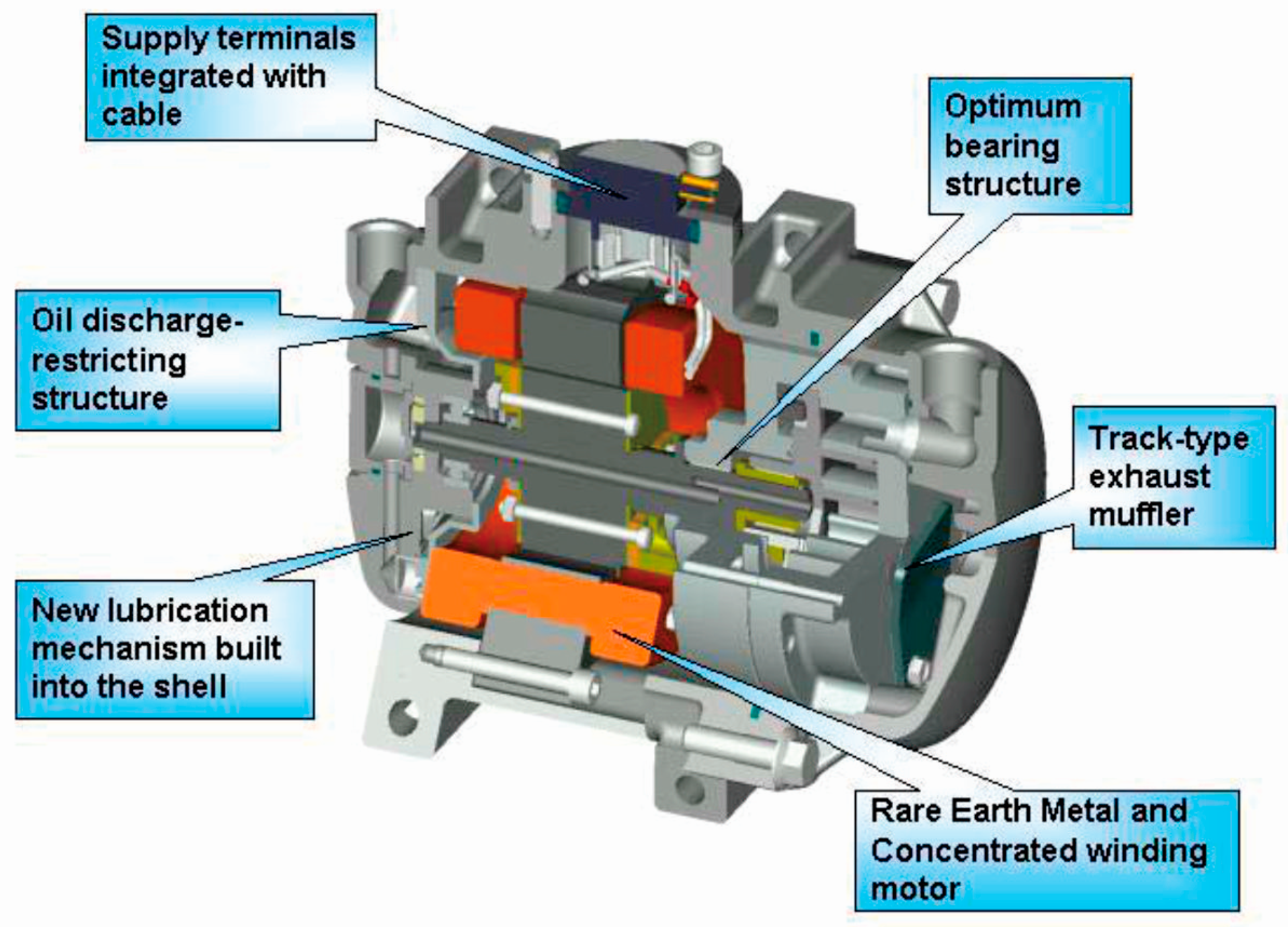
Many scholars have focused on improving the performance of diverse components and parts of the heat pump AC, especially the compressor and heat exchangers. The electric scroll compressor is the most common type used in the AC systems of EVs. It has been widely accepted automakers like Toyota, BYD, Denso and so on [44,45,46,47]. Makino et al. [48] developed an electric compressor with various technologies as shown in Figure 4. This compressor had high reliability, low vibration and noise, small size and light weight, and high efficiency. At the same time, it showed superior comfort and cooling performance, equivalent to that of current engine-driven compressors. To further enhance the electric compressor performance and efficiency, the drive motor was included in [49,50,51]. Besides of the electric scroll compressor, other types of compressors were also proposed for the EV heat pump AC system. Wei et al. [52] presented experimental investigations of an EV heat pump AC system separately integrated with a swash plate variable displacement compressor, a scroll compressor and an electric scroll compressor. For the ambient temperature of −10 °C, the average vehicle cabin temperatures were 12 °C, 10 °C and 5 °C, respectively. The conclusions showed that, when the ambient temperature was below −10 °C, the average vehicle cabin temperature using the swash plate based system was higher than using the other two options. That is to say, the swash plate variable displacement compressor is a good choice for an EV heat pump AC system in low temperature environments. A type of vane compressor with double working cavities that was driven by a frequency modulated electric motor was designed in [53]. There was no obvious difference in performance between the new compressor and the electric scroll compressor, while the former compressor was distinctive in simple structure, manufacture and assembly. Therefore, it can be applied to EV heat pump AC systems instead of the electric scroll compressor. In [54], a miniature electrically driven turbocompressor was presented. The measurements showed that the heating, ventilation, and AC system with this turbocompressor had an ultra-compact size and high efficiency. Sakai et al. [55] developed a 2-way driven compressor, but this compressor can only be used in hybrid EVs. Although these novel compressors were developed, there are more tasks that must be completed before they can be widely applied in EVs, except for the electric scroll compressor.
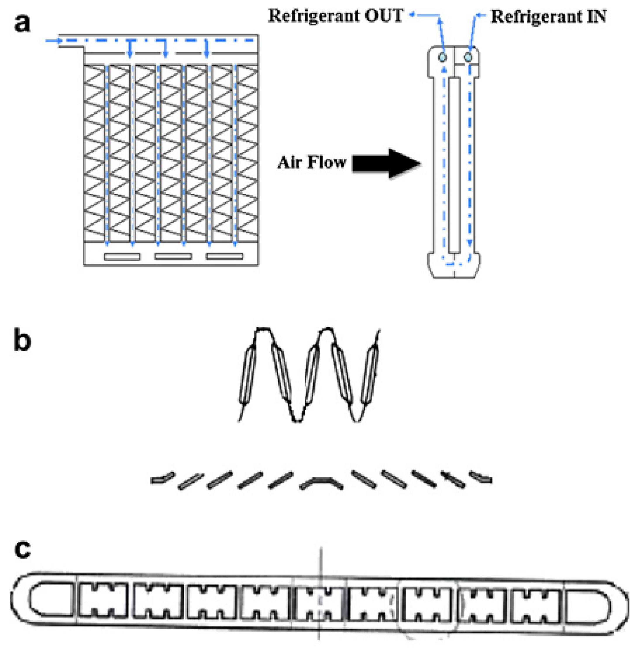
In addition to compressors, heat exchangers also have research highlights. Cummings et al. [56] performed a comprehensive review of testing of AC heat exchangers in vehicles. They evaluated the actual performance of condensers and evaporators of AC systems through wind tunnel testing and road tests. Huang et al. [57] investigated the frosting characteristics of an air-source heat pump by varying the fin type of the outdoor heat exchanger. Under frosting conditions, the decreasing orders of both the average and the maximum values of the heating capacity, COP and input power were flat, wavy and wavy/slit fins. The average values of heating capacity, COP and input power for the wavy/slit fins, compared with the flat fins, were decreased by 14.57%, 8.26% and 7.11%, respectively. This conclusion provides a basis for selecting the fin type for outdoor heat exchangers. AC systems with micro-channel heat exchangers were proposed in [58,59,60]. The representative micro-channel evaporator is shown in Figure 5 [60].
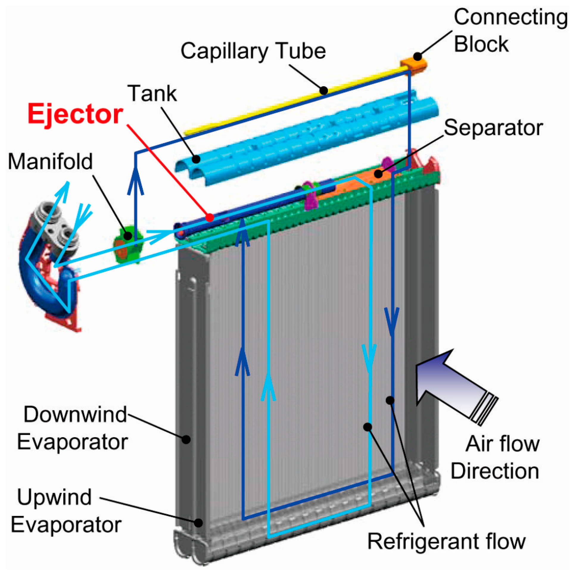
Compared with the use of fin-tube heat exchangers, the cooling and heating efficiencies of heat pump AC systems were increased by at least 20% with the use of micro-channel heat exchangers over a constant heat transfer area [58]. Besides higher-efficiency, the micro-channel heat exchangers have other advantages such as a neeed for less refrigerant charge, compactness and low cost. The heat pump AC system (using micro-channel heat exchangers) was applied to EVs by Wu et al. [61]. They concluded that the size of the indoor and outdoor heat exchangers decreased by 57.6% and 62.5%, respectively, so the AC weight was effectively reduced, which contributed to an increase in the mileage of the EV. At the same time, this system could cut the refrigerant charge by 26.5%, which reduced the greenhouse effect. The disadvantages of this system were also presented in this paper. The AC system frequently worked on the defrosting cycle in cold weather conditions, which immensely affected the heating capacity and the heating performance coefficient. Denso developed an ejector integrated evaporator, as shown in Figure 6, to reduce the power consumption of vehicle cabin AC systems [62]. The ejector system was introduced into the market May 2009. However, the noise and the temperature distribution were two main challenges in developing an evaporator with integrated ejector.
2.4. Innovative System Structure
Reforming the integral structure of the heat pump AC system for the EV is also a widely popular approach. Wang et al. [63] adopted three heat exchangers instead of a four-way valve to achieve cooling and heating for an EV cabin. They concluded that the heat pump AC system with three heat exchangers had advantages in demisting and dehumidifying, but the capacity and COP of this system were slightly lower than that of the heat pump AC system with a four-way valve. Suzuki et al. [47] proposed a representative system structure of the AC system for EVs. The construction and mechanism are shown in Figure 7.
With the two heat exchangers in the interior unit, the system could not only provide cooling, heating and demisting/dehumidifying, but also ensure safe driving when the operation mode was switched from cooling to heating. Subsequently, Xie and Min et al. measured the performance of this representative heat pump AC system [64,65]. In [66], an internal heat exchanger was installed in an automobile AC system to improve system performance. In [67,68], a suction line heat exchanger was added to a car AC system. The results showed that both the capacity and the COP could be improved by up to 25%, while the compressor discharge temperatures were also increased. Furthermore, Ahn et al. [69] compared the performance of the AC, heat pump and dual-evaporator heat pump systems, which were all combined with a heater. The experimental results showed that the dual-evaporator heat pump system as shown in Figure 8, had a superior performance in the dehumidifying and heating operation compared with the other two systems. The specific moisture extraction rate and COP of the dual-evaporator heat pump system were 53% and 62% higher, respectively, than those of the heat pump system at the indoor air wet bulb temperature of 13 °C. Moreover, the specific moisture extraction rate and COP of the heat pump system were 154% and 180% higher, respectively, than the AC system at the indoor air wet bulb temperature of 15 °C.
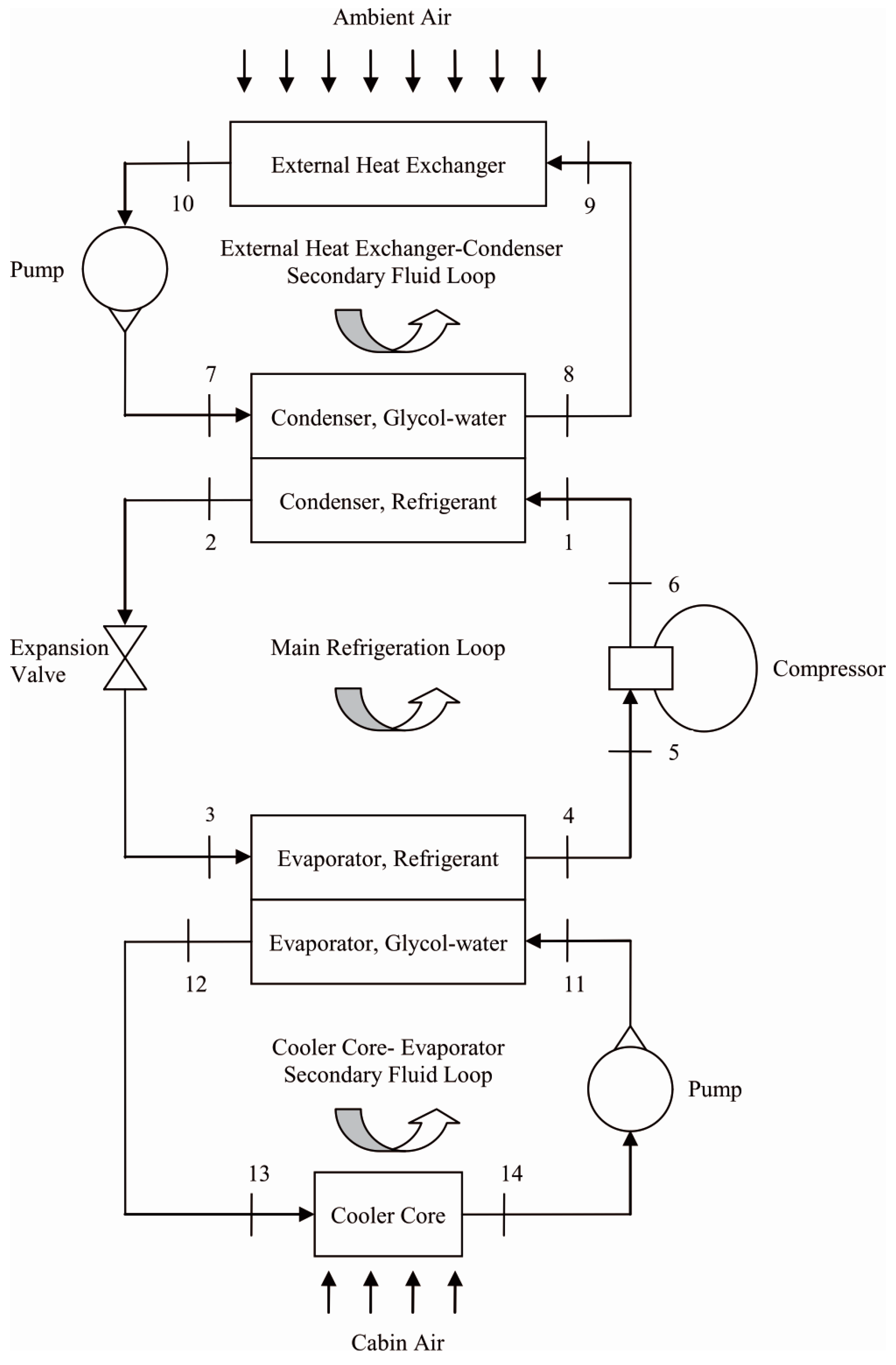
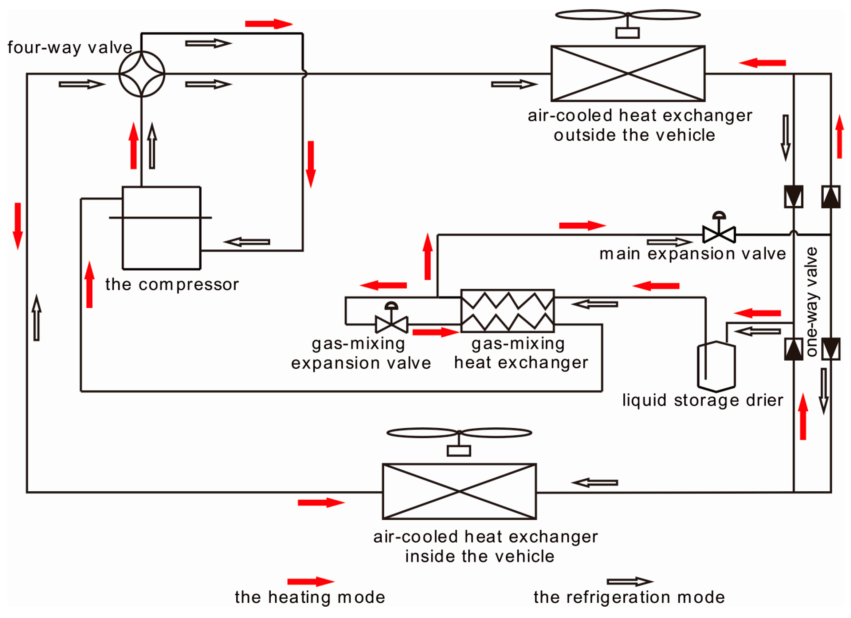
A dual-loop cooling and heating system for automotive applications was designed and fabricated [70,71]. The structure and flow diagram of the dual-loop system in cooling mode are shown in Figure 9 [70]. In addition to the main refrigeration loop, the system had two separate secondary fluid loops using a 50% glycol-water mixture to exchange energy with the refrigeration loop. The experimental results showed that the COP of this system varied from 0.9 to 1.8 in cooling mode, while for the heating mode it varied from 2 to 5, depending on the outdoor air conditions. A heat pump cycle with an economizer and a modified reciprocating was introduced [72]. For mobile application, the heat pump with Voorhees economizer demonstrated better performance compared to the conventional heat pump without economizer when the evaporating temperature is lower than −20 °C. It could increase the capacity at low ambient temperatures of more than two times. Wang [73] took the two-stage cycle technology and applied it in a rail vehicle AC. Li et al. [74,75] presented a low temperature heat pump AC system for fully EVs based on the two-stage compression refrigeration cycle as shown in Figure 10. They studied the characteristics of this system by simulation and experimentation. The results revealed that, when the environment temperature was −20 °C, the system could still run normally with a COP of 1.5. At the same time, it also possessed good performance under standard cooling and heating condition [75]. That is to say, this system could steadily and efficiently extend its operating range.
The improvement of defrosting method in addition to using the two-stage cycle technology to increase the heating performance, was another research hotspot. As described in [76,77], defrosting the heat supply and energy consumption adversely impacted the heating performance. To decrease this influence, Qu et al. [78] reported two control strategies for the electronic expansion valve. They investigated the two control strategies effects on reverse-cycle defrosting performance of an air source heat pump. Zhang et al. [79] compared the three defrosting methods, i.e., reverse cycle defrosting, hot gas bypass defrosting and phase change thermal energy storage defrosting. The experimental results indicated that the defrosting method, which used phase change thermal energy storage, could shorten defrosting time and reduce energy consumption [80].
3. Multiple Source Heat Pump AC Systems
The single source heat pump AC system can be qualified to heat and cool for EVs in most weather conditions by the abovementioned methods. However the heating capacity and heating COP drop sharply with decreasing outdoor temperature. The heating capacity is insufficient in extremely cold weather. To solve these problems, many authors have proposed multiple source heat pump systems.
3.1. Additional Waste Heat Source
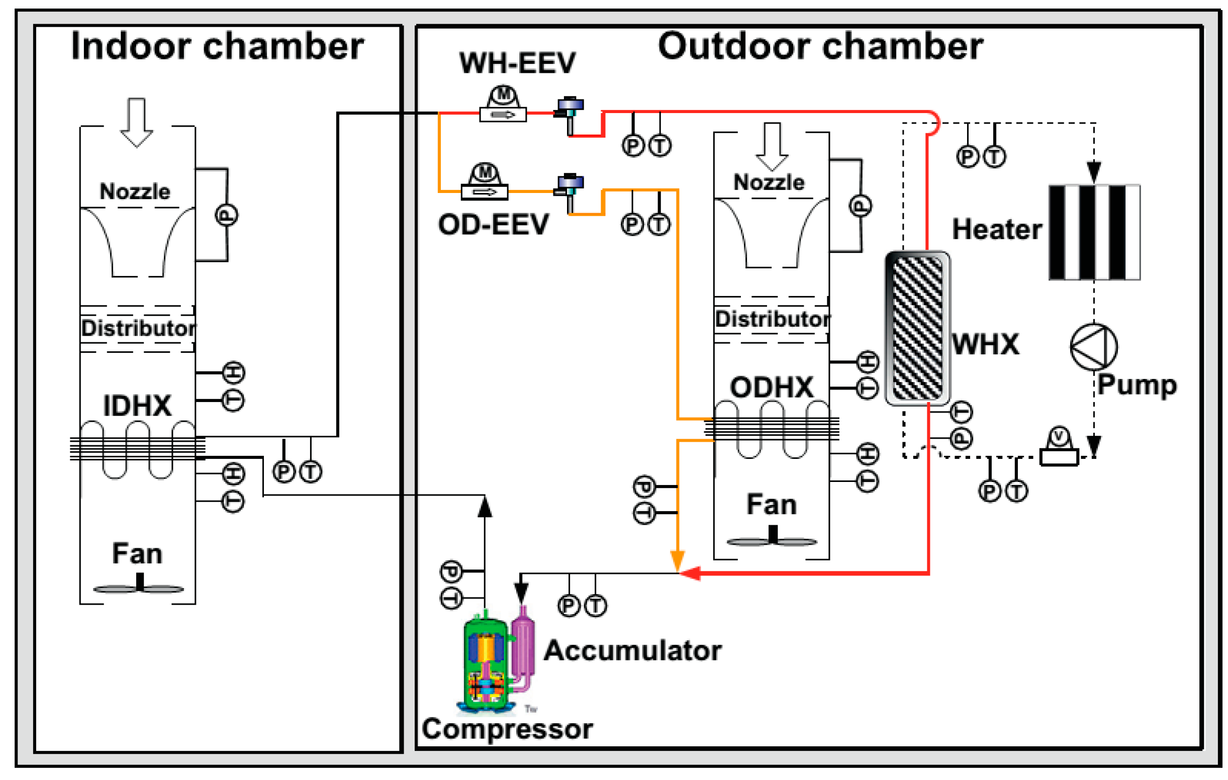
Waste heat discharged from electric devices, such as motors, batteries and inverters of fully EVs, is available. However, it is greatly insufficient for heating the cabin directly. To maximize the use of the waste heat, an integrated climate control system was developed by Groupe Enerstat Inc. [81]. The test results showed that the use of a dual source heat pump, which uses both air and waste heat, was one of the best methods for EVs. Promme [82] proposed a reversible heat pump system with an additional heat source which could utilize the waste heat of the battery, driven electric motor and electronic control unit. Ahn and Woo [83,84] investigated a dual source heat pump (using both air and waste heat) in EVs, which is shown in Figure 11.
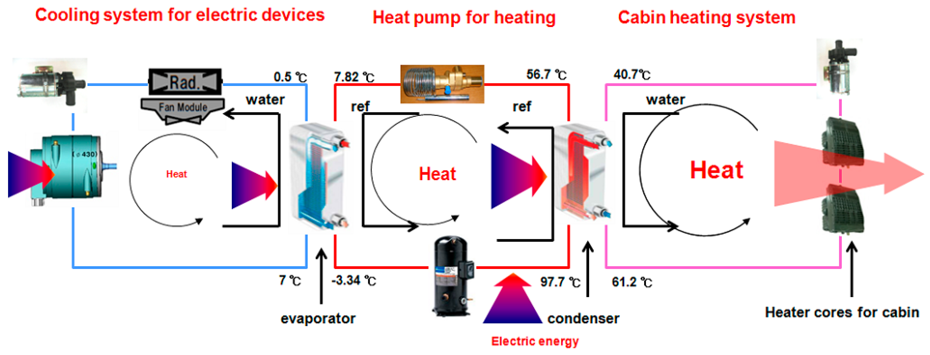
They compared the heating performance of the dual source heat pump in various operation modes: air source-only, waste heat-only and dual heat sources. The experimental results indicated that the heating capacity and COP in the dual source heat pump were increased by 20.9% and 8.6%, respectively, compared to those of the air source-only heat pump system, while it became very close to the waste heat-only mode at low outdoor temperature. Cho et al. [85] measured the heating performance of a coolant source heat pump, which used waste heat from electric devices on an electric bus. As shown in Figure 12, the test setup was composed of a refrigerant loop, an air circulation loop, and a coolant loop. Both an evaporator and a condenser, with plate heat exchangers, were installed for the purpose of exchanging heat between the refrigerant and the coolant source using the waste heat from the electric devices. The same heat transfer mechanism was adopted in [86,87]. Besides of the feasibility of integrating a heat pump into the AC system of the EV, both cooling and heating performances under various experimental conditions, including variations in outdoor and indoor temperatures, the water flow rate for the condenser and the evaporator sides, were investigated [86]. The system was also optimized by varying the refrigerant charge and the compressor frequency as well as using a control algorithm for operational energy management. The proposed heat pump AC system could meet target power capacities which had been set as 28 kW of cooling and 26 kW of heating with COPs of more than 1.6 for cooling and 2.6 for heating, which were required for system energy efficiency and customer comfort [87]. The target energy consumption by cooling and heating had been met at less than 20% and 25% of the total electrical energy consumption of the electric bus, respectively. Zou et al. [88] also presented a heat pump AC system coupled with the battery cooling system. The authors declared that the battery dissipation heat was not only a useful heat source for the heat pump AC system, especially at low outdoor temperature, but also an additional cooling load since the ambient temperature was too high to dissipate the battery heat to the ambient air directly.
Kim and Lee focused on heating performance enhancement of the CO2 heat pump system using waste heat from the stacks in fuel cell EVs [89,90]. In [89], a heater core that used stack coolant was placed upstream of a cabin heater to preheat incoming air into the cabin heater. The performance of this heat pump system with heater core was compared with that of a conventional heating system with heater core and that of a heat pump system without heater core. The heating capacity of the heat pump system with heater core, which used recovered heat from the stack coolant, was improved by 100% over the heat pump system without heater core and by 70% over the conventional heating system with heater core. Furthermore, the coolant to the air heat pump system with heater core showed a significantly better performance than the air to air heat pump system with heater core. Lee et al. [90] concluded that when the waste heat from the stack coolant was used as the evaporating heat source, the heat pump using R744 could provide sufficient heating capacity and heating COP under cold weather conditions.
3.2. Supplemental External Heat Source
In addition to the waste heat discharged from interior electric devices in EVs, as an assisted heat source, there are other heat pump combined systems with external heat. Solar-assisted heat pump AC systems are one interesting option for EV climate control systems since solar cells can not only provide a heat insulating layer, but also recharge the battery. This concept was also applied to motor train units by Yin [91]. In [92], a solar controller and an AC controller were designed. The solar controller managed the battery fatures, such as charging and over-discharging protection, and communicated with the vehicle control system. The experimental results showed that the solar-assisted heat pump AC system could operate stably in the heating mode as well as in the cooling mode. In [93], solar cells covered the roof of a compact car, and could generate about 225 W of power. The solar-assisted heat pump AC system could improve the refrigerating capacity by about 8%, which significantly reduced the peak cooling load and the driving mileage losses of the EV. Zhao [94] declared that two hours of generating electricity capacity by a solar panel could keep the solar-assisted system running for half an hour.
In [95], a heat pump system with integrated thermoelectric modules was proposed. The authors discussed the application of this technique to provide supplemental heating for EVs. At an ambient temperature of −17.8 °C, the integrated automotive AC system could achieve an additional 2 kW of heating capacity with almost the same COP compared to the heat pump system without thermoelectric modules. The test results showed that this integrated system could increase the heating capacity in an energy-efficient way, especially for cold climate operation.
The PTC heater is another additional heat source. Kim et al. [96] investigated a combined system consisting of a heat pump and a PTC heater as a heating unit in EVs. Compared to the standard of the PTC heater at an indoor temperature of 20 °C, the heating capacity was increased by 59% for the combined system, and the COP was increased by 100% for the heat pump system. The conclusions showed that the heat pump cycle should be always operated for better efficiency, and the PTC heater should be controlled for better performance. Therefore the PTC heater and heat pump combined system is an optional AC system for EVs, especially in extremely cold weather conditions.
4. Conclusions
The heat pump AC system seems to be the most reasonable solution to control the climate of EVs, although there are currently many other solutions used in EVs. In this paper, an extensive literature review has been performed on the progress of heat pump AC systems for the EV.
Not only single air source heat pump systems, which have been widely considered by many researchers, have been comprehensively analyzed, but also multiple source heat pump systems have been included. In single air source heat pump AC systems, many advanced technologies and strategies were described, such as alternative refrigerants, the inverter technology, novel components, as well as innovative system structures. These advanced technologies can improve the AC system efficiency and vehicle mileage as verified in the cited reports. Furthermore, the multiple source heat pump system is also a useful method to enhance the cooling/heating capacity and the COP of the AC system in EV, especially in cold weather conditions. The heat sources include air, waste heat, solar heat, water and so on.
Considering the tremendous development in the heat pump AC system field, it is worthwhile to be mindful that there is no one single technology that can obtain ideal results to control the climate in an EV all year round. A combination of several of these technologies is still necessary more often than not. Although some of the innovative technologies described in this paper are still part of on-going research, we believe the real practical application in EVs is imminent. The integrated heat pump AC system based on the two-stage CO2 cycle, which is equipped with a variable capacity compressor and uses the waste heat from electric devices as an additional heat source, should be considered for EVs in the coming research.
Acknowledgments
This work was supported by the Industry-University-Research Institute Collaboration Fund of Guangdong Province (No. 2011B090400572), Strategic Emerging Industry Development Fund of Guangdong Province (No. [2011]891), Natural Science Foundation of Guangdong Province (No. S2012010010199), Science and Technology Innovation Fund Project of Foshan City (No. 2013AG100063).
Conflicts of Interest
The authors declare no conflict of interest.
References
- Mei, V.C.; Chen, F.C.; Mathiprakasam, B.; Heenan, P. Study of solar-assisted thermoelectric technology for automobile air conditioning. J. Sol. Energy 1993, 115, 200–205. [Google Scholar] [CrossRef]
- Ma, G.Y. Study on thermoelectric air conditioning for electric vehicles. Refrig. Air Cond. 1998, 14, 5–10. [Google Scholar]
- Cao, Z.Y. Solution to air conditioning on EVs. Auto Electric. Parts 2008, 47, 1–4. [Google Scholar]
- Zhang, J.Z. Structural features of fully electric air conditioning system. Automob. Maint. 2006, 12, 4–5. [Google Scholar]
- Guyonvarch, G.; Aloup, C.; Petitjean, C. Savasse ADMD. 42V Electric Air Conditioning Systems (E-A/CS) for Low Emissions, Architecture, Comfort and Safety of Next Generation Vehicles; SAE Technical Paper No. 2001-01-2500; SAE International: Warrendale, PA, USA, 2001. [Google Scholar]
- Randall, B. Blowing Hot and Cold. Available online: https://www.teslamotors.com/blog/blowing-hot-and-cold (accessed on 20 December 2006).
- Torregrosa, B.; Payá, J.; Corberán, J.M. Modeling of mobile air conditioning systems for electric vehicles. In Proceedings of the 4th European Workshop—Mobile Air Conditioning and Vehicle Thermal Systems, Torino, Italy, 1–2 December 2011.
- Lee, D. Experimental study on the heat pump system using R134a refrigerant for zero-emission vehicles. Int. J. Automot. Technol. 2015, 16, 923–928. [Google Scholar] [CrossRef]
- Qi, Z.G. Advances on air conditioning and heat pump system in electric vehicles—A review. Renew. Sustain. Energy Rev. 2014, 38, 754–764. [Google Scholar] [CrossRef]
- Shi, B.X.; Ma, G.Y.; Chen, G.S. Research on heat pump systems for electric vehicle air conditioning. Fluid Mach. 2002, 30, 48–50. [Google Scholar]
- Billiard, F. Refrigeration and air conditioning: What’s new at regulatory level. In Proceedings of the Ninth European Conference on Technological Innovations in Refrigeration, Air Conditioning and in the Food Industry, Milano, Italy, 29–30 June 2001.
- European Parliament (EUROPA). Regulation (EC) No. 842/2006 of the European Parliament and of the Council of 17 May 2006 on certain fluorinated greenhouse gases. Off. J. Eur. Union 2006, L161, 1–11. [Google Scholar]
- European Parliament (EUROPA). Directive 2006/40/EC of the European Parliament and of the Council of 17 May 2006 relating to emissions from air-conditioning systems in motor vehicles and amending council directive 70/156/EEC. Off. J. Eur. Union 2006, L161, 12–18. [Google Scholar]
- Pettersen, J.; Lorentzen, G. A New, Efficient and Environmentally Benign System for Automobile Air Conditioning; SAE Technical Paper No. 931129; SAE International: Warrendale, PA, USA, 1993. [Google Scholar]
- McEnaney, R.; Hrnjak, P. Clutch Cycling Mode of Compressor Capacity Control of Transcritical R744 Systems Compared to R134a Systems; SAE Technical Paper No. 2005-01-2033; SAE International: Warrendale, PA, USA, 2005. [Google Scholar]
- Petersen, M.; Bowers, C.; Elbel, S.; Hrnjak, P. Development of high-efficiency carbon dioxide commercial heat pump water heater. HVAC R Res. 2013, 19, 823–835. [Google Scholar]
- Hafner, A. Experimental Study on Heat Pump Operation of Prototype CO2 Mobile Air Conditioning System. In Proceedings of the 4th IIR-Gustav Lorentzen Conference on Natural Working Fluids; International Institute of Refrigeration (IRR): Paris, France, 2000. [Google Scholar]
- Hafner, A.; Pettersen, J.; Skaugen, G.; Nekså, P. An Automobile HVAC System with CO2 as the Refrigerant. IIR. In Proceedings of the Gustav Lorentzen Conference Natural Working Fluids; International Institute of Refrigeration (IRR): Paris, France, 1998. [Google Scholar]
- Hafner, A.; Jakobsen, A.; Nekså, P.; Pettersen, J. Life Cycle Climate Performance (LCCP) of Mobile Air-conditioning Systems. In Proceedings of the Verband der Automobilindustrie (VDA) Alternate Refrigerant Wintermeeting, Saafelden, Austria, 18–19 February 2004.
- Tamura, T.; Yakumaru, Y.; Nishiwaki, F. Experimental study on automotive cooling and heating air conditioning system using CO2 as a refrigerant. Int. J. Refrig. 2005, 28, 1302–1307. [Google Scholar] [CrossRef]
- Kim, S.C.; Won, J.P.; Kim, M.S. Effects of operating parameters on the performance of a CO2 air conditioning system for vehicles. Appl. Therm. Eng. 2009, 29, 2408–2416. [Google Scholar] [CrossRef]
- Kim, M.H.; Pettersen, J.; Bullard, C.W. Fundamental process and system design issues in CO2 vapor compression systems. Prog. Energy Combust. 2004, 30, 119–174. [Google Scholar] [CrossRef]
- Kim, S.C.; Kim, M.S.; Hwang, I.C.; Lim, T.W. Performance evaluation of a CO2 heat pump system for fuel cell vehicles considering the heat exchanger arrangements. Int. J. Refrig. 2007, 30, 1195–1206. [Google Scholar] [CrossRef]
- Lee, M.Y.; Lee, H.S.; Won, H.P. Characteristic evaluation on the cooling performance of an electrical air conditioning system using R744 for a fuel cell electric vehicle. Energies 2012, 5, 1371–1383. [Google Scholar] [CrossRef]
- Ma, Y.T.; Liu, Z.Y.; Tian, H. A review of transcritical carbon dioxide heat pump and refrigeration cycles. Energy 2013, 55, 156–172. [Google Scholar] [CrossRef]
- Zou, Y.; Hrnjak, P. Effects of fluid properties on two-phase flow and refrigerant distribution in the vertical header of a reversible microchannel heat exchanger-Comparing R245fa, R134a, R410A and R32. Appl. Therm. Eng. 2014, 70, 966–976. [Google Scholar] [CrossRef]
- Wongwises, S.; Kamboon, A.; Orachon, B. Experimental investigation of hydrocarbon mixtures to replace HFC-134a in an automotive air conditioning system. Energy Convers. Manag. 2006, 47, 1644–1559. [Google Scholar] [CrossRef]
- Hoffmann, G.; Plehn, W. Natural Refrigerants for Mobile Air-Conditioning in Passenger Cars; German Federal Environment Agency Press Office: Dessau, Germany, 2010; pp. 1–10. [Google Scholar]
- Chamoun, M.; Rulliere, R.; Haberschill, P.; Berail, J.F. Dynamic model of an industrial heat pump using water as refrigerant. Int. J. Refrig. 2012, 35, 1080–1091. [Google Scholar] [CrossRef]
- Zhao, Y. Study on the Performance of Automotive Air Conditioning Systems with R1234yf. Ph.D. Thesis, Shanghai Jiao Tong University, Shanghai, China, 2012. [Google Scholar]
- Lee, Y.H.; Jung, D.S. A brief performance comparison of R1234yf and R134a in a bench tester for automobile applications. Appl. Therm. Eng. 2012, 35, 240–242. [Google Scholar] [CrossRef]
- Seybold, L.; Hill, W.; Zimmer, C. Internal Heat Exchanger Design Performance Criteria for R134a and HFO-1234yf; SAE Technical Paper No. 2010-01-1210; SAE International: Warrendale, PA, USA, 2010. [Google Scholar]
- Qi, Z.G. Experimental study on evaporator performance in mobile air conditioning system using HFO-1234yf as working fluid. Appl. Therm. Eng. 2013, 53, 124–130. [Google Scholar] [CrossRef]
- Ghodbane, M. An Investigation of R152a and Hydrocarbon Refrigerants in Mobile Air Conditioning; SAE Technical Paper No. 1999-01-0874; SAE International: Warrendale, PA, USA, 1999. [Google Scholar]
- Ghodbane, M.; Baker, J.A.; Kadle, P.S. Potential Applications of R-152a Refrigerant in Vehicle Climate Control Part II; SAE Technical Paper No. 2004-01-0918; SAE International: Warrendale, PA, USA, 2004. [Google Scholar]
- Hosoz, M.; Direk, M. Performance evaluation of an integrated automotive air conditioning and heat pump system. Energy Convers. Manag. 2006, 47, 545–559. [Google Scholar] [CrossRef]
- Saiz Jabardo, J.M.; Gonzales Mamani, W.; Ianella, M.R. Modeling and experimental evaluation of an automotive air conditioning system with a variable capacity compressor. Int. J. Refrig. 2002, 25, 1157–1172. [Google Scholar] [CrossRef]
- Shao, S.Q.; Shi, W.X.; Li, X.T.; Yan, Q.S. Study on the adjusting performance of variable frequency air conditioning system. Refrig. Air Cond. 2001, 1, 17–20. [Google Scholar]
- Lee, J.; Byun, J.S. Experiment on the performance improvement of air-to-air heat pump adopting the hot gas bypass method by outdoor fan speed variation. J. Mech. Sci. Technol. 2009, 23, 3407–3415. [Google Scholar] [CrossRef]
- Peng, Q.H.; Du, Q.G. Performance evaluation of a variable frequency heat pump air conditioning system for electric bus. IJFMS 2015, 8, 13–22. [Google Scholar] [CrossRef]
- Yeh, T.J.; Chen, Y.J.; Hwang, W.Y.; Lin, J.L. Incorporating fan control into air-conditioning systems to improve energy efficiency and transient response. Appl. Therm. Eng. 2009, 29, 1955–1964. [Google Scholar] [CrossRef]
- Shi, W.X.; Shi, B.H.; Yan, Q.S. Three control algorithms for air conditioners with frequency control. Heat Vent. Air Cond. 2000, 30, 16–19. [Google Scholar]
- Li, N.; Xia, L.; Deng, S.M.; Xu, X.G.; Chan, M.Y. Dynamic modeling and control of a direct expansion air conditioning system using artificial neural network. Appl. Energy 2012, 91, 290–300. [Google Scholar] [CrossRef]
- Zhang, J.Z. Structure characteristics of electric air-conditioning system in Prius car. Automob. Maint. 2006, 8, 4–5. [Google Scholar]
- Li, S. BYD: Active research on air-conditioning system for green car. Refrig. Air Cond. 2015, 15, 85–86. [Google Scholar]
- Li, X.H. Development and application of frequency conversion air conditioner with electric heat pump for electric bus. Bus Technol. Res. 2009, 31, 23–25. [Google Scholar]
- Suzuki, T.; Ishii, K. Air Conditioning System for Electric Vehicle; SAE Technical Paper No. 960688; SAE International: Warrendale, PA, USA, 1996. [Google Scholar]
- Makino, M.; Ogawa, N.; Abe, Y.; Fujiwara, Y. Automotive Air-Conditioning Electrically Driven Compressor; SAE Technical Paper No. 2003-01-0734; SAE International: Warrendale, PA, USA, 2003. [Google Scholar]
- Naidu, M.; Nehl, T.W.; Gopalakrishnan, S.; Wurth, L. Electric Compressor Drive with Integrated Electronics for 42 V Automotive HVAC Systems; SAE Technical Paper No. 2005-01-1318; SAE International: Warrendale, PA, USA, 2005. [Google Scholar]
- Hwang, K.Y.; Park, G.B.; Cho, H.S. Design of IPMSM for the Electrical Compressor in EV; SAE Technical Paper No. 2011-28-0063; SAE International: Warrendale, PA, USA, 2011. [Google Scholar]
- Baumgart, R.; Aurich, J.; Ackermann, J.; Danzer, C. Comparison and Evaluation of a New Innovative Drive Concept for the Air Conditioning Compressor of Electric Vehicles; SAE Technical Paper No. 2015-26-0045; SAE International: Warrendale, PA, USA, 2015. [Google Scholar]
- Wei, M.S.; Huang, H.S.; Song, P.P.; Peng, S.Z.; Wang, Z.X.; Zhang, H. Experimental investigations of different compressors based electric vehicle heat pump air-conditioning systems in low temperature environment. In Proceedings of the IEEE Transportation Electrification Conference and Expo, ITEC Asia-Pacific, Beijing, China, 31 August–3 September 2014.
- Chen, G.S.; Shi, B.X.; Ma, G.Y. The simulating test of vane compressor with double working cavity. J. Guangdong Univ. Technol. 2000, 17, 11–14. [Google Scholar]
- Krahenbuhl, D.; Zwyssig, C.; Weser, H.; Kolar, J.W. A miniature 500000-r/min electrically driven turbo compressor. IEEE Trans. Ind. Appl. 2010, 46, 2459–2466. [Google Scholar] [CrossRef]
- Sakai, T.; Ueda, M. 2-Way Driven Compressor for Hybrid Vehicle Climate Control System; SAE Technical Paper No. 2004-01-0906; SAE International: Warrendale, PA, USA, 2004. [Google Scholar]
- Cummings, R.W.; Shah, R.K. Experimental Performance Evaluation of Automotive Air-Conditioning Heat Exchangers as Components and in Vehicle Systems; SAE Technical Paper No. 2005-01-2003; SAE International: Warrendale, PA, USA, 2005. [Google Scholar]
- Huang, D.; Liu, X.Y.; Wang, Y.L. Effect of fin type on frosting characteristics of an air-source heat pump. J. Refrig. 2012, 33, 12–17. [Google Scholar]
- Liu, N.; Li, J.M.; Li, H.Q. Performance research on heat pump air conditioner using micro-channel heat exchangers. Refrig. Air Cond. 2011, 11, 96–99. [Google Scholar]
- Zhang, L. Analysis of performance of air conditioners with micro-channel heat exchangers. Refrig. Technol. 2010, 30, 33–36. [Google Scholar]
- Qi, Z.G.; Zhao, Y.; Chen, J.P. Performance enhancement study of mobile air conditioning system using microchannel heat exchangers. Int. J. Refrig. 2010, 33, 301–312. [Google Scholar] [CrossRef]
- Wu, J.H.; Xie, F.; Liu, C.P.; Ouyang, G. Adaptability Research on micro-channel heat exchanger applied to heat pump air conditioning system for electrical vehicle. J. Mech. Eng. 2012, 48, 141–147. [Google Scholar] [CrossRef]
- Brodie, B.R.; Takano, Y.; Gocho, M. Evaporator with Integrated Ejector for Automotive Cabin Cooling; SAE Technical Paper No. 2012-01-1048; SAE International: Warrendale, PA, USA, 2012. [Google Scholar]
- Wang, Y.; Shi, J.Y.; Chen, J.P.; Wang, X.N.; Kang, Z.J. Comparative study of two kinds of automotive air conditioning system with three heat exchangers and four-way valve. J. Refrig. 2014, 35, 71–76. [Google Scholar]
- Xie, Z. Research of Electrical Vehicle Heat Pump Air Conditioner and Its Automatic Control System. Master’s Thesis, Shanghai Jiao Tong University, Shanghai, China, 2006. [Google Scholar]
- Min, H.T.; Wang, X.D.; Zeng, X.H.; Li, S. Parameter design and computation study for air conditioning system of electric vehicle. Automob. Technol. 2009, 40, 19–22. [Google Scholar]
- Cho, H.; Lee, H.; Park, C. Performance characteristics of an automobile air conditioning system with internal heat exchanger using refrigerant R1234yf. Appl. Therm. Eng. 2013, 61, 563–569. [Google Scholar] [CrossRef]
- Boewe, D.; Yin, J.; Park, Y.C.; Bullard, C.W.; Hrnjak, P.S. The Role of Suction Line Heat Exchanger in Transcritical R744 Mobile A/C Systems; SAE Technical Paper No. 1999-01-0583; SAE International: Warrendale, PA, USA, 1999. [Google Scholar]
- Li, G.Q.; Yuan, X.L.; Xu, H.T.; Li, M.X. Application of sution line heat exchanger for R134a automotive air-conditioning system. J. Refrig. 2002, 2, 56–59. [Google Scholar]
- Ahn, J.H.; Kang, H.; Lee, H.S.; Kim, Y. Performance characteristics of a dual-evaporator heat pump system for effective dehumidifying and heating of a cabin in electric vehicles. Appl. Energy 2015, 146, 29–37. [Google Scholar] [CrossRef]
- Jokar, A.; Hosni, M.H.; Eckels, S.J. New Generation Integrated Automotive Thermal System; SAE Technical Paper No. 2005-01-3476; SAE International: Warrendale, PA, USA, 2005. [Google Scholar]
- Jokar, A.; Hosni, M.H.; Eckels, S.J. A heat pump for automotive application. In Proceedings of the 8th International Energy Agency Heat Pump Conference, Las Vegas, NY, USA, 30 May–2 June 2005.
- Zha, S.; Hafner, A.; Neksa, P. Investigation of R-744 Voorhees transcritical heat pump system. Int. J. Refrig. 2008, 31, 16–22. [Google Scholar] [CrossRef]
- Wang, X.J. Application of low-temperature heat pump technology in rail vehicle air conditioning. Mech. Electr. Eng. Technol. 2011, 40, 165–168. [Google Scholar]
- Li, H.J.; Zhou, G.H.; Li, A.G.; Li, X.G.; Chen, J. Simulation study on characteristics of ultra-low temperature heat pump air conditioning system for pure electric vehicles. Appl. Mech. Mater. 2014, 580–583, 2475–2479. [Google Scholar] [CrossRef]
- Li, H.J. Study on Performance of Low Temperature Heat Pump Air-Conditioning System for Pure Electric Vehicle. Ph.D. Thesis, Xi’An University of Architecture and Technology, Xian, China, 2015. [Google Scholar]
- Dong, J.K.; Deng, S.M.; Jiang, Y.Q.; Xia, L.; Yao, Y. An experimental study on defrosting heat supplies and energy consumptions during a reverse cycle defrost operation for an air source heat pump. Appl. Therm. Eng. 2012, 37, 380–387. [Google Scholar] [CrossRef]
- Lee, M.Y.; Kim, Y.C.; Lee, D.Y. Experimental study on frost height of round plate fin-tube heat exchangers for mobile heat pumps. Energies 2012, 5, 3479–3491. [Google Scholar] [CrossRef]
- Qu, M.L.; Xia, L.; Deng, S.M.; Jiang, Y.Q. An experimental investigation on reverse-cycle defrosting performance for an air source heat pump using an electronic expansion valve. Appl. Energy 2012, 97, 327–333. [Google Scholar] [CrossRef]
- Zhang, J.; Lan, J.; Du, R.H.; Gao, G.F. The performance comparison of several defrosting modes for air-source heat pump. J. Refrig. 2012, 33, 47–49. [Google Scholar]
- Dong, J.K.; Jiang, Y.Q.; Yao, Y.; Hu, W.J. Experimental study of the characteristic of defrosting for air source heat pump with phase change energy storage. J. Hunan Univ. 2011, 38, 18–22. [Google Scholar]
- Bilodeau, S. High Performance Climate Control for Alternative Fuel Vehicle; SAE Technical Paper No. 2001-01-1719; SAE International: Warrendale, PA, USA, 2001. [Google Scholar]
- Pomme, V. Reversible Heat Pump System for an Electrical Vehicle; SAE Technical Paper No. 971772; SAE International: Warrendale, PA, USA, 2001. [Google Scholar]
- Ahn, J.H.; Kang, H.; Lee, H.S.; Jung, H.W.; Baek, C.; Kim, Y. Heating performance characteristics of a dual source heat pump using air and waste heat in electric vehicles. Appl. Energy 2014, 119, 1–9. [Google Scholar] [CrossRef]
- Woo, H.S.; Ahn, J.H.; Oh, M.S.; Kang, H.; Kim, Y.C. Study on the heating performance characteristics of a heat pump system utilizing air and waste heat source for electric vehicles. Air Cond. Refrig. Eng. 2013, 25, 180–186. [Google Scholar] [CrossRef]
- Cho, C.W.; Lee, H.S.; Won, J.P.; Lee, M.Y. Measurement and evaluation of heating performance of heat pump systems using wasted heat from electric devices for an electric bus. Energies 2012, 5, 658–669. [Google Scholar] [CrossRef]
- Lee, D.Y.; Cho, C.W.; Won, J.P.; Park, Y.C.; Lee, M.Y. Performance characteristics of mobile heat pump for a large passenger electric vehicle. Appl. Therm. Eng. 2013, 50, 660–669. [Google Scholar] [CrossRef]
- Suh, I.S.; Lee, M.; Kim, J.; Oh, S.T.; Won, J.P. Design and experimental analysis of an efficient HVAC (heating, ventilation, air-conditioning) system on an electric bus with dynamic on-road wireless charging. Energy 2015, 81, 262–273. [Google Scholar] [CrossRef]
- Zou, H.M.; Jiang, B.; Wang, Q.; Tian, C.Q.; Yan, Y.Y. Performance analysis of a heat pump air conditioning system coupling with battery cooling for electric vehicles. Energy Procedia 2014, 61, 891–894. [Google Scholar] [CrossRef]
- Kim, S.C.; Kim, M.S.; Hwang, I.C.; Lim, T.W. Heating performance enhancement of a CO2 heat pump system recovering stack exhaust thermal energy in fuel cell vehicles. Int. J. Refrig. 2007, 30, 1215–1226. [Google Scholar] [CrossRef]
- Lee, H.S.; Won, J.P.; Cho, C.W.; Kim, Y.C.; Lee, M.Y. Heating performance characteristics of stack coolant source heat pump using R744 for fuel cell electric vehicles. J. Mech. Sci. Technol. 2012, 26, 2065–2071. [Google Scholar] [CrossRef]
- Yin, J. Theoretic Study of Motor Train Unit of Solar Air Conditioning System. Master’s Thesis, Southwest Jiaotong University, Chengdu, China, 2012. [Google Scholar]
- Sun, H. Research of Automatic Control System of the Solar-Assisted Air-Conditioning for Pure Electric Vehicle. Master’s Thesis, Nanchang University, Nanchang, China, 2012. [Google Scholar]
- Ma, G.Y.; Shi, B.X.; Wu, L.Z.; Chen, G.S. Study on solar-assisted heat pump system for electric vehicle air conditioning. Acta Energiae Sol. Sin. 2001, 22, 176–180. [Google Scholar]
- Zhao, C. Soar-Assisted System Study of Automobile Air Conditioner Based on Parallel Technology. Master’s Thesis, Heifei University of Technology, Hefei, China, 2012. [Google Scholar]
- Okuma, T.; Radermacher, R.; Hwang, Y. A novel application of thermoelectric modules in an HVAC system under cold climate operation. J. Electron. Mater. 2012, 41, 1749–1758. [Google Scholar] [CrossRef]
- Kim, K.Y.; Kim, S.C.; Kim, M.S. Experimental studies on the heating performance of the PTC heater and heat pump combined system in fuel cells and electric vehicles. Int. J. Automot. Technol. 2012, 13, 971–977. [Google Scholar] [CrossRef]
Figure 1.
Schematic diagram of the experimental automotive air conditioning/heat pump system [36].
Figure 1.
Schematic diagram of the experimental automotive air conditioning/heat pump system [36].

Figure 2.
Effects of compressor frequency on the performance and parameters [38].
Figure 2.
Effects of compressor frequency on the performance and parameters [38].

Figure 3.
Schematic diagram of the artificial neural network-based controller arrangement [43].
Figure 3.
Schematic diagram of the artificial neural network-based controller arrangement [43].

Figure 4.
Main element technologies of the electric compressor [48].
Figure 4.
Main element technologies of the electric compressor [48].

Figure 5.
Schematic diagram of the microchannel evaporator: (a) Front view (left) and side view (right) of the microchannel evaporator; (b) Louver fin used in the microchannel evaporator; (c) Microchannel tube [60].
Figure 5.
Schematic diagram of the microchannel evaporator: (a) Front view (left) and side view (right) of the microchannel evaporator; (b) Louver fin used in the microchannel evaporator; (c) Microchannel tube [60].

Figure 6.
Ejector evaporator structure [62].
Figure 6.
Ejector evaporator structure [62].

Figure 7.
Air conditioning system structure and operation for electric vehicles [47].
Figure 7.
Air conditioning system structure and operation for electric vehicles [47].

Figure 8.
Schematic diagram of the dual-evaporator heat pump system for electric vehicles [69].
Figure 8.
Schematic diagram of the dual-evaporator heat pump system for electric vehicles [69].
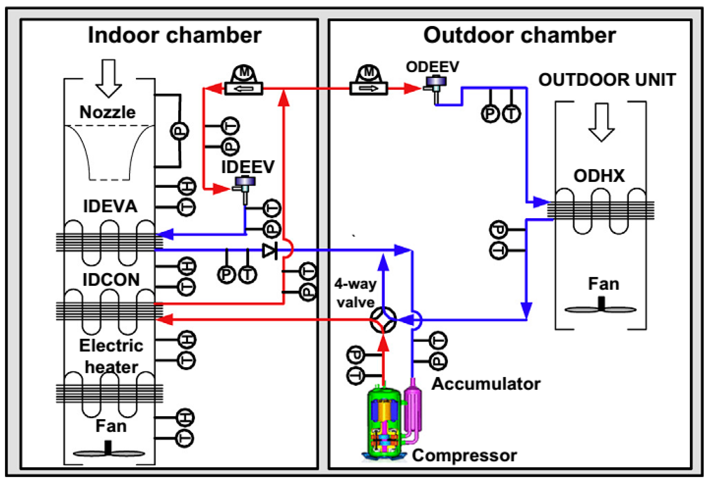
Figure 9.
Ejector evaporator structure [70].
Figure 9.
Ejector evaporator structure [70].

Figure 10.
Schematic of gas-mixing heat pump system for fully EVs [74].
Figure 10.
Schematic of gas-mixing heat pump system for fully EVs [74].

Figure 11.
Schematic diagram of the dual heat source heat pump [83].
Figure 11.
Schematic diagram of the dual heat source heat pump [83].

Figure 12.
Heat transfer mechanism of the heat pump system using waste heat from electric devices [85].
Figure 12.
Heat transfer mechanism of the heat pump system using waste heat from electric devices [85].

© 2016 by the authors; licensee MDPI, Basel, Switzerland. This article is an open access article distributed under the terms and conditions of the Creative Commons by Attribution (CC-BY) license (http://creativecommons.org/licenses/by/4.0/).
Share and Cite
MDPI and ACS Style
Peng, Q.; Du, Q. Progress in Heat Pump Air Conditioning Systems for Electric Vehicles—A Review. Energies 2016, 9, 240. https://doi.org/10.3390/en9040240
AMA Style
Peng Q, Du Q. Progress in Heat Pump Air Conditioning Systems for Electric Vehicles—A Review. Energies. 2016; 9(4):240. https://doi.org/10.3390/en9040240
Chicago/Turabian StylePeng, Qinghong, and Qungui Du. 2016. "Progress in Heat Pump Air Conditioning Systems for Electric Vehicles—A Review" Energies 9, no. 4: 240. https://doi.org/10.3390/en9040240
Note that from the first issue of 2016, this journal uses article numbers instead of page numbers. See further details here.