Article

Development of an ICE-Based Micro-CHP System Based on a Stirling Engine; Methodology for a Comparative Study of its Performance and Sensitivity Analysis in Recreational Sailing Boats in Different European Climates

1
Defense University Center, Naval Academy, Marín 36920, Spain
2
ETS Ingenieros Industriales, University of Vigo, Vigo 36310, Spain
*
Author to whom correspondence should be addressed.
Energies 2016, 9(4), 239; https://doi.org/10.3390/en9040239
Submission received: 30 December 2015 / Revised: 2 March 2016 / Accepted: 21 March 2016 / Published: 25 March 2016
(This article belongs to the Special Issue Simulation of Polygeneration Systems)

Abstract

:
Micro combined heating and power (micro-CHP) systems are becoming more than important, and even essential, if we pretend to take full advantage of available energy. The efficiency of this kind of systems reaches 90% and important savings in energy transport processes can occur. In this research, an internal combustion engine (ICE)-based micro-CHP system was developed and tested under specific constraints. The system uses a two cylinder Otto engine as prime mover, coupled to an electrical alternator, and it uses exhaust gases and engine cooling circuit heat. The micro-CHP system was developed to match the electrical power of a typical Stirling engine (SE)-based micro-CHP unit, in order to later compare both systems’ performance under similar circumstances. Different operating modes were tested under different engine speeds, in order to find the optimum operating point. A stand-alone portable application of this system was performed using recreational sailing boats as mobile homes. Specific considerations had to be taken, related to boundary conditions with sea water, and a transient simulation was performed, considering the boat under three different European climates. Results were compared for the different locations and the performance of the equipment shown. A comparative study with the SE-based micro-CHP system performance was done, and a sensitivity analysis of the influence of the battery size was carried out under the same conditions. The SE and ICE-based proposed micro-CHP system have similar behavior, except for the differences found due to the electric/thermal power ratios in both systems. Battery bank size sensitivity analysis reflects a limit in performance improvement. This limit is caused by the uniform distribution of electrical demand profile.

1. Introduction

An energy model based on micro-cogeneration units or distributed models is meant to represent a very feasible future [1]. High fuel prices and power demands require more efficient models such as smart grids where losses are minimized due to distributed generation concepts, and the waste heat is useful unlike in the majority of thermal power plants. The size of the plant is very important in order to get a reduction in the greenhouse gas emissions [2,3]. Distributed generation systems can adapt to unpredicted changes in the demand and provide interconnectivity of many different devices through the grid [4,5]. Technologies like micro-cogeneration, which are able to provide many economic and environmental advantages, are the proposed solution in the majority of cases for distributed generation systems in dwellings [6,7,8,9].
For better efficiency purposes, micro combined heating and power (micro-CHP) technologies have been embedded together with renewable systems, providing important primary energy reduction [10,11,12,13]. Even alone, the use of cogeneration units produces important raises in efficiency as a result. If a thermal machine produces only electric power, efficiencies around 40% can be achieved, but if the system incorporates cogeneration functions, this efficiency can increase up to 90% [14], however, the most typical domestic heating system in Europe is still a conventional condensation boiler [15].
The particular application will determine the kind of micro-cogeneration technology to be selected. The most commonly used technologies are internal combustion engines (ICEs), micro-turbines, Stirling engines (SEs), Rankine cycles, or fuel cells, among others [14,16,17] although the last two ones are still entering the market. These technologies have been widely studied. Thus, for example, in [18] 16 CHP system units representing different technologies were evaluated from the energetic, economic and environmental points of view.
Building integration of micro-CHP systems is one of the main applications of distributed systems, and many studies have been developed on this topic. ICE-based micro-CHP systems are also considered for this application, from different perspectives [19,20].
Studies on the feasibility of micro-CHP technologies in many different countries can be found in the literature. Many research reports indicate that satisfactory results can be achieved in small-scale domestic applications, enabling reductions in primary energy consumption [21,22,23,24,25].
In [2] the annual operating hours of these technologies together with thermophotovoltaic generators when the cogeneration plant supplies energy to two dwellings with different sizes were evaluated. Proper thermal energy storage (TES) size is also studied for the different technologies. In [26] an exhaustive comparison between a residential gas engine CHP and a fuel cell micro-CHP is made. This work underlines that although the most important issues are the CO2 emissions and the match between the thermal and electric outputs of the CHP system and the consumer’s load profile, the lifecycle cost analysis plays an important role. The paper analyses different micro-CHP systems using different strategies from an economical and an environmental point of view.
In [27] the analysis of the cogeneration system was centered in the coupling of the CHP system with the TES to improve the global efficiency. This coupling, together with an analysis of the electricity market, has been widely studied in the literature [2,15,28,29]. Normally the heating, cooling, domestic hot water (DHW) and power loads do not coincide in time and an uncoupled plant improves the annual efficiency of the whole system. In the micro-CHP plant under study, this decoupling was made achieved by using a water storage tank and a bank of batteries. Moreover thermal storage devices considerably reduce the CO2 emissions and become more economical, especially in large systems. In [2] it is demonstrated that the thermal exhaust from the engine is directly related with the size of the TES.
The applicable governmental regulations of the country where the micro-CHP system is installed and the electricity buyback represent two key factors for sizing TES units [30]. A sensitivity analysis is performed in [31] to estimate the influence of the fuel and electricity prices on the profitability of a micro CHP unit. In [32] a sensitivity analysis of the major economic parameters was performed, focusing on the operational flexibility of the system. An optimization model for the capacity of distributed generation based on micro-CHP units is also presented in [33], where an interesting sensitivity analysis of costs was performed.
Operating strategies are also the topic of some recent studies [34,35,36]. Operating strategies like following the electric load (FEL) and following the thermal load (FTL) are analyzed in [36].
Apart of the legislative framework, the location of the building is also important due to the various climates and consequently due to the different cooling and heating loads. In [34] an economic analysis is made for five different locations. Some works analyzing micro-CHP system performance in mobile homes, considering caravans [37] and recreational sailing boats [38] have been published. A ship power plant operating with waste heat recovery was analyzed in [39,40]. Thermodynamic analyses and efficiency calculations are developed in this research, but the location of the ship was not taken into account.
An ICE-based micro-CHP system was developed and tested in the research reported herein. The system uses a two cylinder Otto engine as prime mover, coupled to an electrical alternator, and it utilizes exhaust gases and engine cooling circuit heat. Different operating modes were tested under different engine speeds, in order to find the optimum operating point. The main design constraint for this system was matching the electrical power to a Stirling engine-based micro-CHP unit, in order to compare both systems’ performances. Typically a Stirling engine-based micro-CHP unit produces less power than ICE-based ones [14].
Mobile homes are very sensitive to energy independence, and there is a lack of studies about them [37]. The micro-CHP system was modeled and simulated in a recreational sailing boat, as an example of a mobile home with some particular features [38]. The annual performance of the system was estimated in different European ports, with different climate conditions. This research was used in present work to compare ICE-based and SE-based technologies.
The system was designed to work in an autonomous way and for this reason no possible combination with a back-up boiler or similar devices was considered. It uses a rank of batteries to store electricity and to supply power during peak periods; and a TES system to match the thermal demand and production.
TRNSYS was used to model and simulate the micro-CHP system and to determine its annual performance. This software is very commonly used among the scientific community and there are many references in the literature where performance analysis is carried out using it [37,38,41,42,43,44].
In this paper, a micro-CHP unit was designed, built and tested. The main features of this ICE-based unit were determined considering a Stirling engine-based unit one, analyzed by the authors in a previous paper [38]. Furthermore, a comparative study with this unit was carried out. Power, efficiency, and suitability of both systems are presented in The Results and Conclusions sections. Moreover, a sensitive analysis of the ICE-based system was done, varying the size of the battery bank. Methodology for a comparative study of the performance of different technologies-based micro-CHP units, together with sensitivity analysis in recreational sailing boats in different European climates, are presented in this paper.

2. Materials and Methods

The ICE-based micro-CHP system developed and tested in this work, the recreational sailing boat features, and the environmental conditions are presented in this section. The system performance simulation configuration is also explained in Section 2.4.

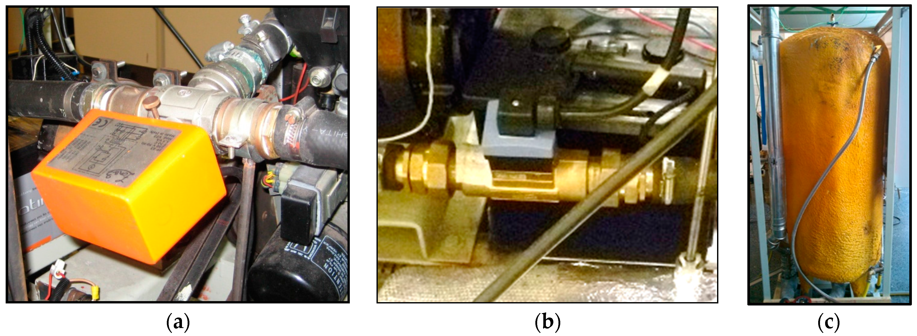
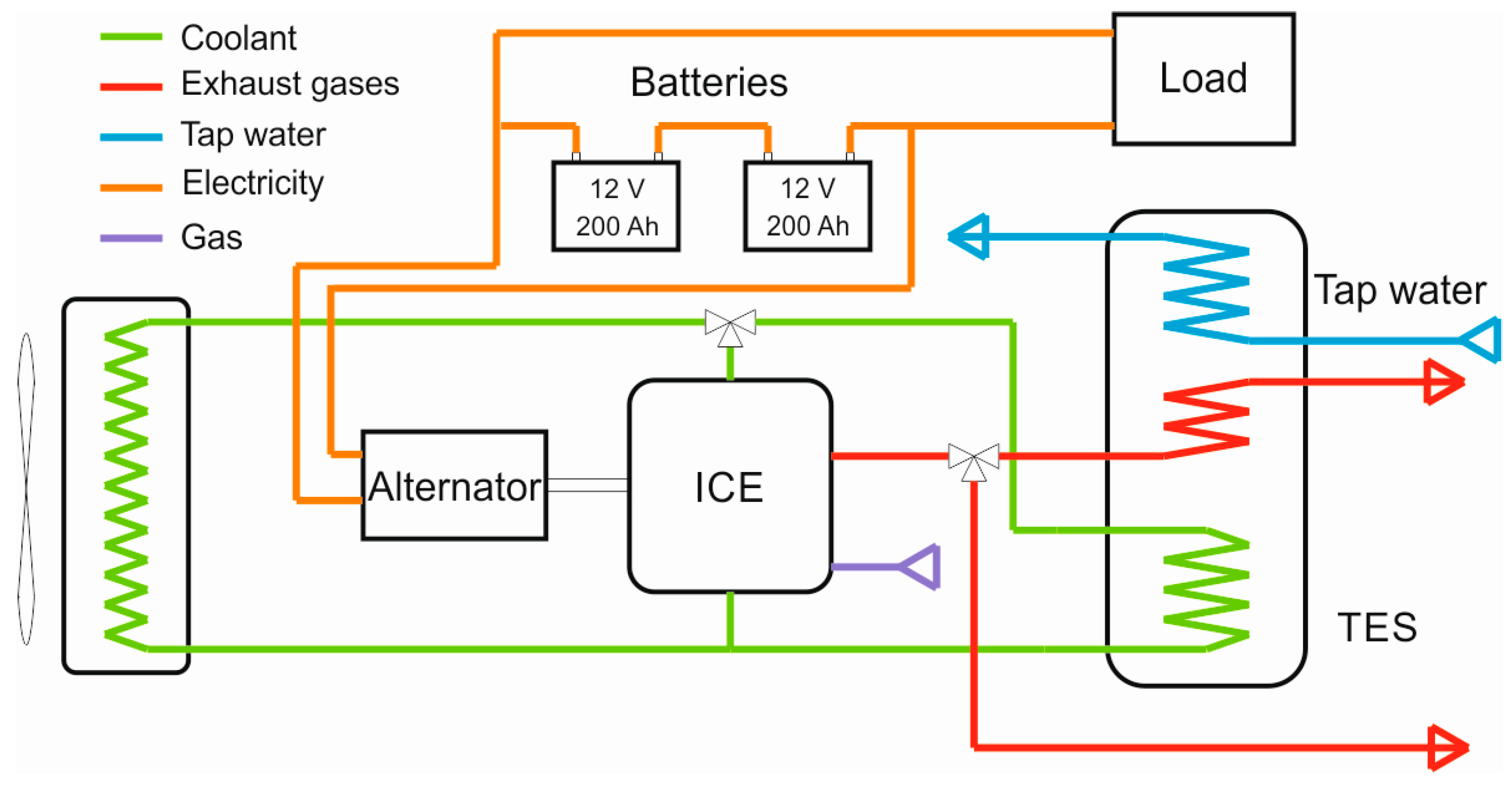
2.1. ICE Based Micro-CHP System

A micro-CHP system was developed using a Honda GX360 gasoline two-cylinder engine as prime mover. The engine was previously adapted to operate using butane as fuel, in order to reduce contaminant emissions, and maintenance costs. This engine is liquid cooled, and a modification in the cooling circuit was made in order to recover waste heat from the refrigeration fluid. Another improvement to recover waste heat from exhaust gases was made. Two three way valves were implemented in the system to recirculate coolant and exhaust gases to the TES coils. A storage tank was designed for heat recovery. Two main heat exchangers were introduced into the tank. The coolant coil is 20 mm in diameter and 12 m length and the exhaust gases heat exchanger is divided into three different coils, 20 mm in diameter and 4 m in length each. Figure 1 shows the three way valve installed in the engine coolant outlet, the flowmeter in the cooling circuit, and a front view of the storage tank.
The temperatures of the coolant and gases range from 120 °C to 500 °C, so the heat recovery potential is quite high. A storage tank is used as heating load, introducing tap water at a specified flow rate to keep the outlet temperature below a specified threshold.
An alternator was chosen to provide a similar amount of electricity as the SE-based micro-CHP unit. The SE-based unit steady state thermal power is 5.93 kW, and the electrical power is 0.92 kW [38]. The system was completed with a bank of batteries to store the electricity produced and a TES to store the heat produced by both recovery systems.
The experimental setup is presented in Figure 2. The ICE-based unit was tested under steady state conditions to obtain its thermal and electric power. Three operating modes were tested using three different engine rotation speeds. The engine manufacturer recommends that the engine operating speeds range from 2000 to 3500 rpm. The selected test speeds were 2100, 2900, and 3500 rpm for low, medium and high engine speed, respectively. An electric load was permanently connected to the battery bank, to prevent that the batteries from becoming fully charged.
The ICE-based micro-CHP system was tested on the laboratory using four controlled circuits (fuel, air-gas, coolant, and exhaust gases). Tap water was used as a thermal load to keep the TES temperature cool enough.
Temperatures entering and leaving the storage tank and flowrates were measured in the coolant and exhaust gas circuits. An energy balance in the storage tank was performed in order to obtain the global heating power.
A PC-based data acquisition system and proper instrumentation for the micro-CHP unit were installed to measure flows and temperature differences, in order to calculate energy rates, in the heat exchangers (cooling circuit and exhaust gases circuit). Multimeters connected to the data acquisition system were used to record voltage and current data, to determine electric power.

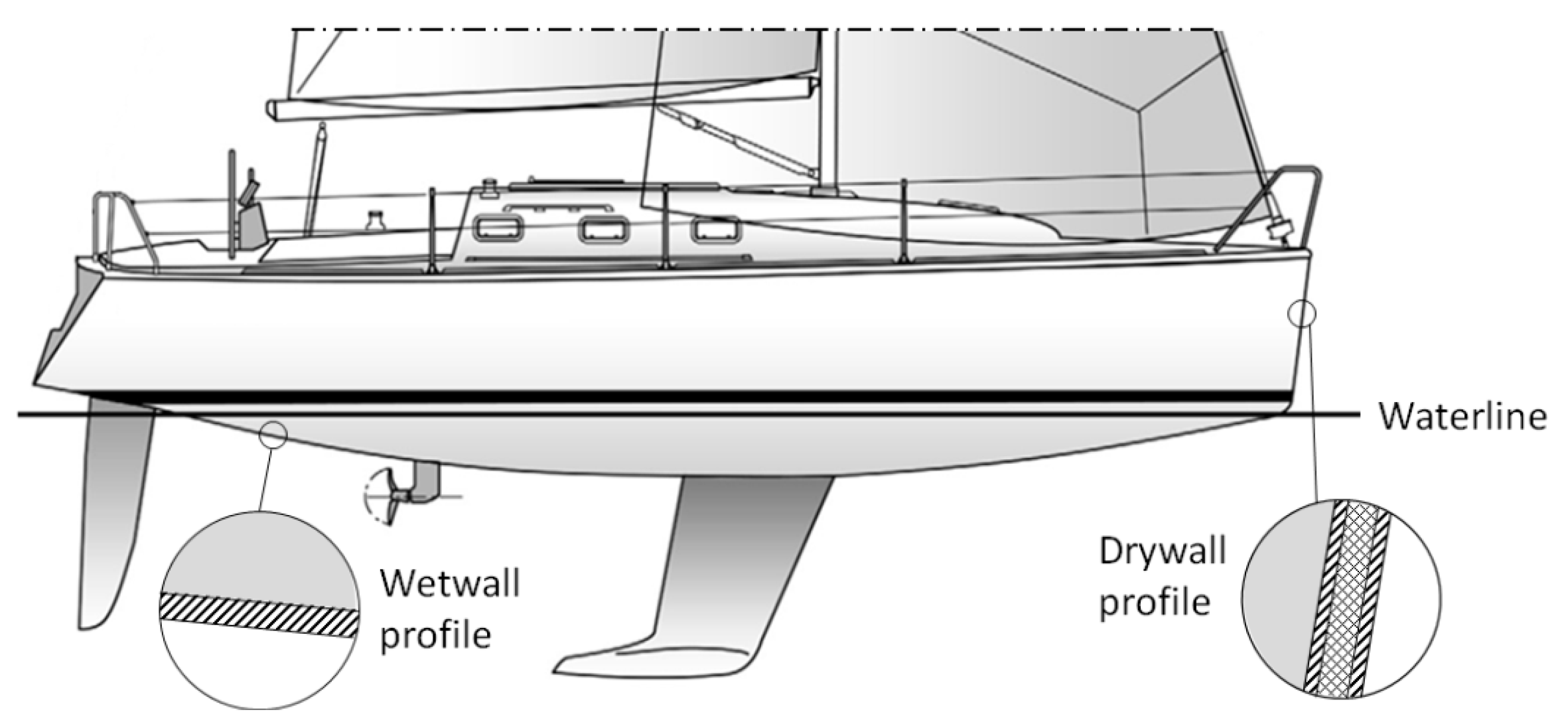
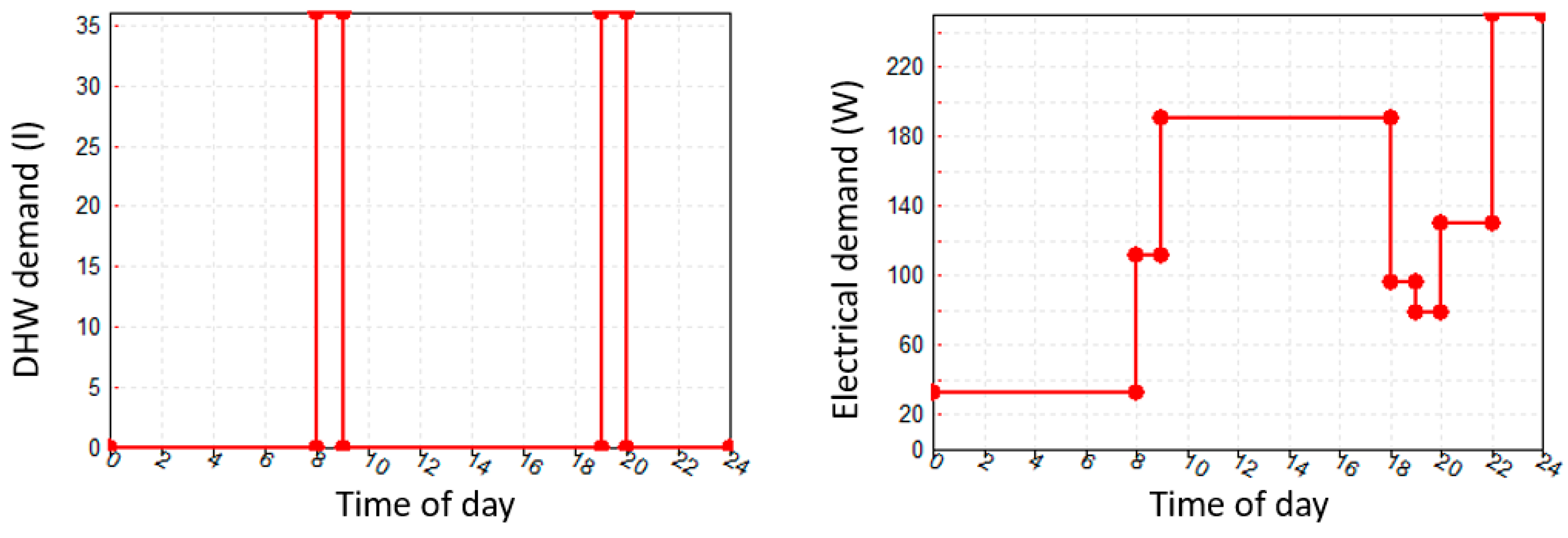
2.2. Recreational Sailing Boat

Sailing boats are the mobile homes selected for this study. Powerboats are less suitable for this kind of application, as they incorporate a thermal engine for movement and an alternator to produce electricity. Sailing boats typically operate with their auxiliary engine turned off, as they only use the engine for mooring. The selected vessel is 10.36 m long and its thermal envelope data was obtained from the manufacturer. Compositions and thicknesses of the walls, ceilings, and floors are shown in Table 1.
Selected ship and energy demands, summarized in Figure 3, are the same as in [38]. In this previous study, the authors carried out a performance analysis of a SE-based micro-CHP system. In addition to ICE-based micro-CHP system performance, a comparative analysis was carried out in the present work, preserving the ship thermal envelope, DHW requirements, and electrical demands. DHW demands were estimated for two people considering two periods of consumption, being adjusted to shower and cooking times.
As shown in Figure 4, ship walls are divided into drywalls and wetwalls, corresponding to the ones in contact with air and with the sea, respectively. Other important parameters imported from the previous study were: air renewal set to 0.6 renovations per hour, and a fixed temperature threshold.
The constant comfort temperature was set to 20 °C. When the inner air temperature went below this temperature, heating was requested from the micro-CHP system; thus, the heating demand depends on the location where the simulation was performed. Global heat demand was determined in the simulation environment, considering DHW demand and heating demand together.

2.3. Environmental Conditions

Average ambient conditions were extracted from the Meteonorm database [45]. A TMY2 standard meteorological file was used for performance analysis in each location under study. Boundary conditions of the ship envelope were not fully defined with data extracted from the TMY2 file. It was necessary to know the boundary conditions in wetwalls. The sea surface temperature (SST) is a typical parameter in global climate databases. For this research, SST data was downloaded from the Community Data Portal [46] that belongs to the National Center for Atmospheric Research (NCAR). Last ten year average data were extracted from a network common data format (netCDF) file, for the locations under study.

2.4. Simulation Configuration

Once the micro-CHP unit was developed and tested, and the environmental boundary conditions were defined, a performance analysis of the system was carried out. A stand-alone operation of the system was defined and applied to a mobile home. A recreational sailing boat was used for this purpose. Ship and heating plant were configured in TRNSYS using standard types. Three different climates were compared in a dynamic simulation. In order to compare the performance results with [38], the selected climates were Northern European Atlantic, Southern European Atlantic, and Mediterranean. One location was selected for each climate: Helsinki (Finland), Breskens (The Netherlands), and Malaga (Spain), respectively.
Dynamic simulation of the system was carried out using steady state experimental data to model the micro-CHP system, due to the fast response of the micro-CHP in start-up and slow-down processes. Inertia systems were introduced for the electrical and thermal storage, to fit the energy demand and production. The battery bank capacity was set to 24 V/100 Ah, and the TES tank volume to 60 L, as in the previous work [38].
The time step was set to 0.1 h for annual simulation, in order to increase convergence. Two simulation layouts were designed for each location, the first one in order to obtain the annual maximum thermal load, and second one in order to obtain the thermal and electrical performance of the system. The first simulation scenario was useful to know the suitability of the micro-CHP system to cover the thermal power demands at any moment during the whole year. The set point temperature was 20 °C in both scenarios. In the second simulation scenario the ship was not only linked to weather components, but it was also connected to the designed thermal and electrical plants.
For the TRNSYS dynamic simulation some aspects were considered. Weather data TMY2 files, obtained from Meteonorm, are monthly mean data for the location. Furthermore, the typical meteorological year was a good agreement with long-term average measured data [47].

3. Results and Discussion

Experimental results of the ICE-based micro-CHP unit are presented first. Then, the suitability of the unit in the different climate zones is shown. Thermal loads were calculated using TRNSYS. The performance of the ICE-based micro-CHP unit is presented and a comparative study with the SE-based micro-CHP unit, for the same climate zones, is also presented. Finally, a sensitivity analysis is shown for the ICE system, considering battery bank size variation.

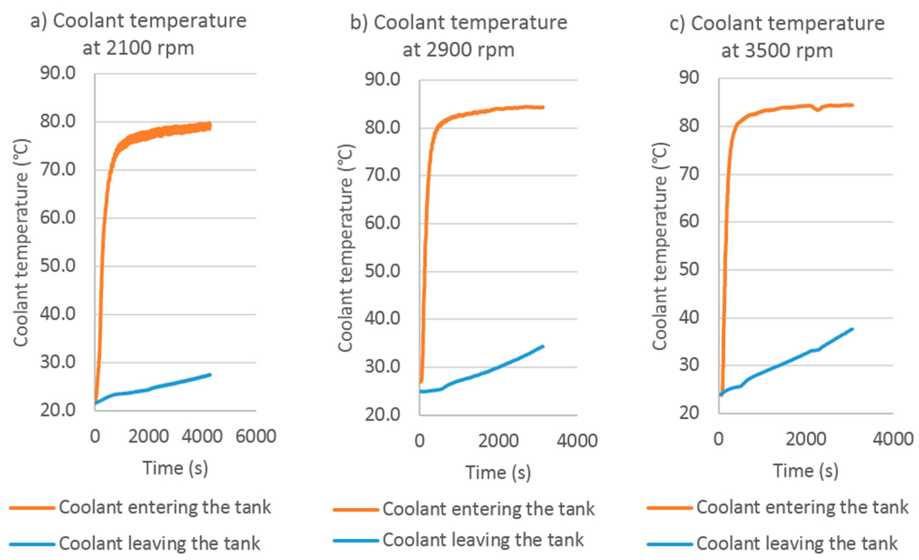
3.1. Experimental Results

The ICE based micro-CHP unit was tested under different conditions to obtain the steady state generated power. For this purpose, both, heat exchanged with the TES and the power to load and to batteries were measured.
Figure 5 shows the experimental results for the coolant temperature entering and leaving the storage tank, using three different engine speeds. Temperature difference is used to determine the thermal energy extracted from the coolant. Global thermal energy production is determined with an energy balance in the storage tank, when coolant and exhaust gases circuits are connected. Coolant temperatures show that micro-CHP reached a steady state after working for 200–500 s. Steady state mean data are then considered for simulation purposes.
Energy produced during the steady state is shown in Table 2. The most suitable engine speed to fit the performance of the SE-based micro-CHP system is the higher one: 3500 rpm. Heating power is very similar in both units and this is the most important feature when comparing the performance under a FTL strategy simulation. Power is a little lower in the ICE-based unit, but it is interesting to compare both systems electrically. The battery bank plays a very important role when analyzing the performance of the micro-CHP system. Thus, a sensitivity analysis was performed, varying the size of the battery bank.

3.2. Adequacy of the Micro-CHP Unit

The model developed in TRNSYS, considering ship envelope and environmental conditions (i.e., climate data and SST) was tested for a temperature set of 20 °C. Simulation results are shown in Table 3, where maximum heat demand is presented, in addition to time of the event and climate conditions. As it was expected, Helsinki, in the Northern European Atlantic zone, is the coolest location, while Malaga, at the Mediterranean, is the hottest. The maximum peak demand corresponds to the Northern European Atlantic scenario, with 4.35 kW.
The suitability of the equipment to meet heat demands is guaranteed in all studied climates. Engine speed should adapt to peak demand, in order to be equal or less than the maximum peak demand. The chosen speed for the performance dynamic simulations was 2900 rpm, slightly higher than the maximum peak demand in the coolest location. It is necessary to have some wiggle room, because DHW demand was not considered for this peak demand study.

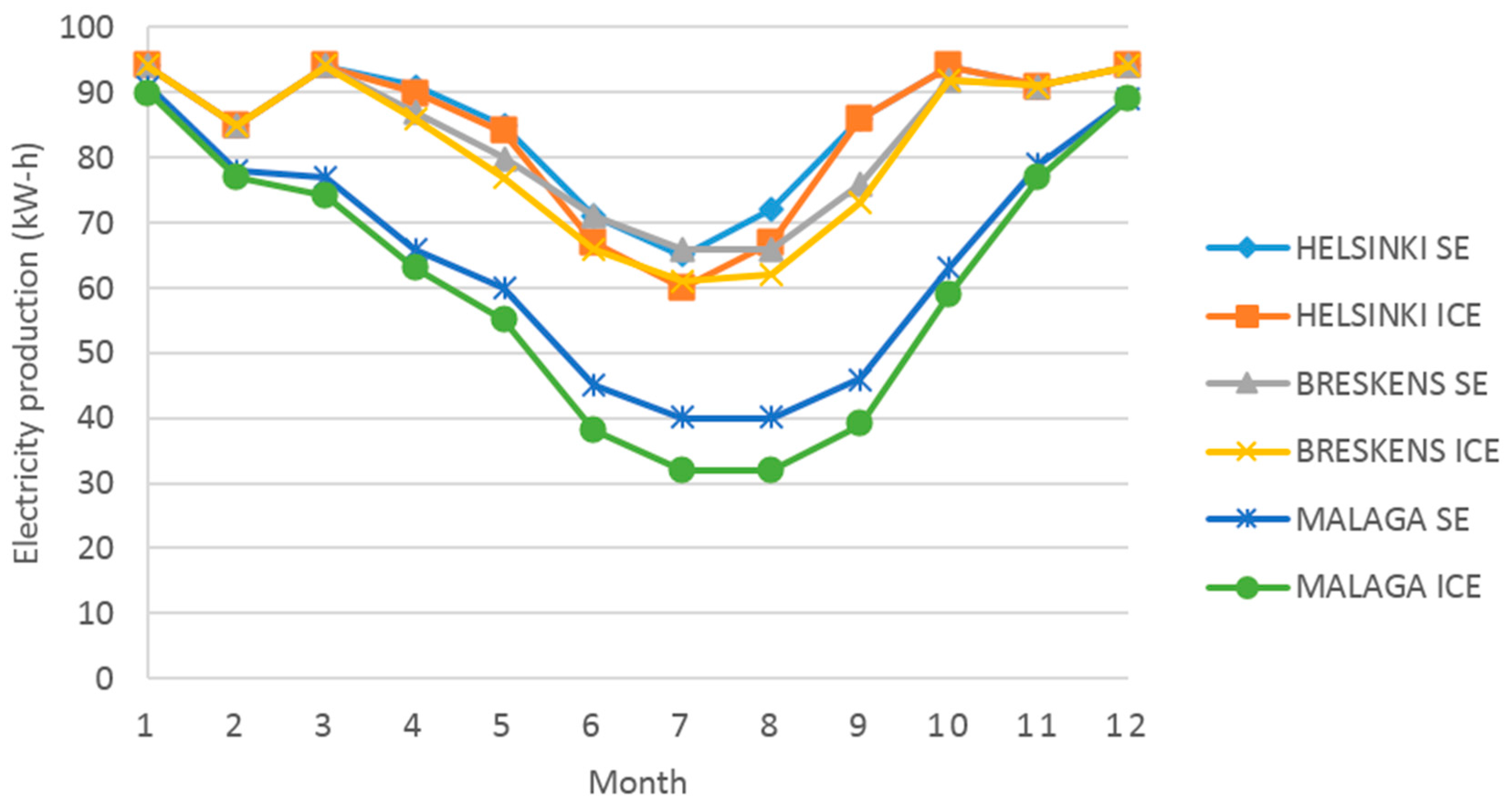
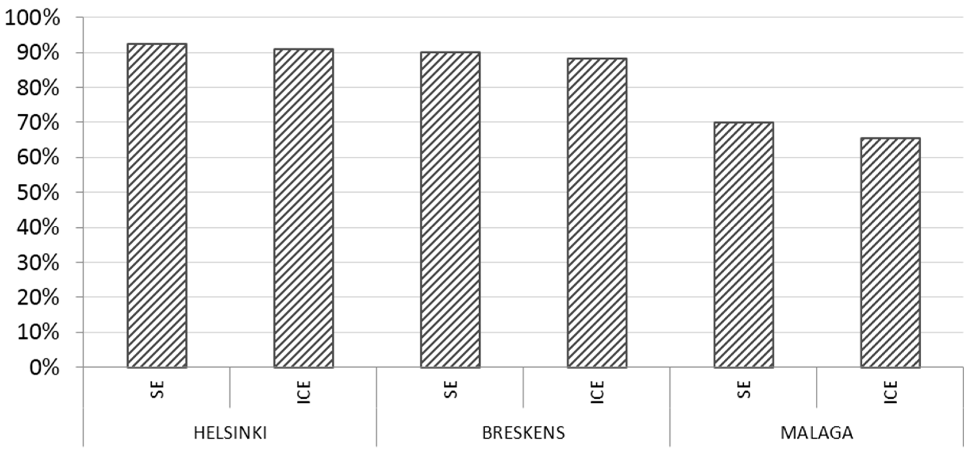
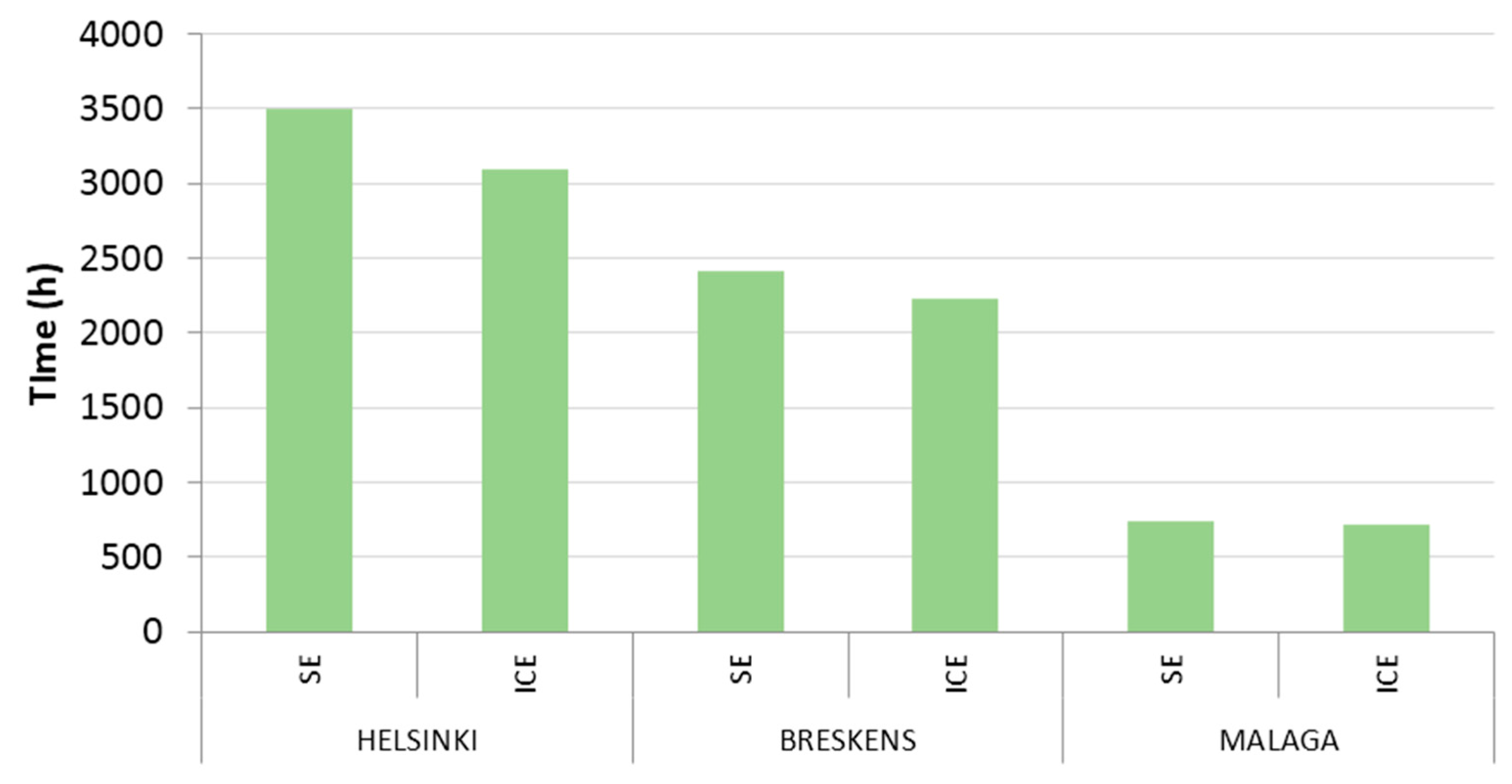
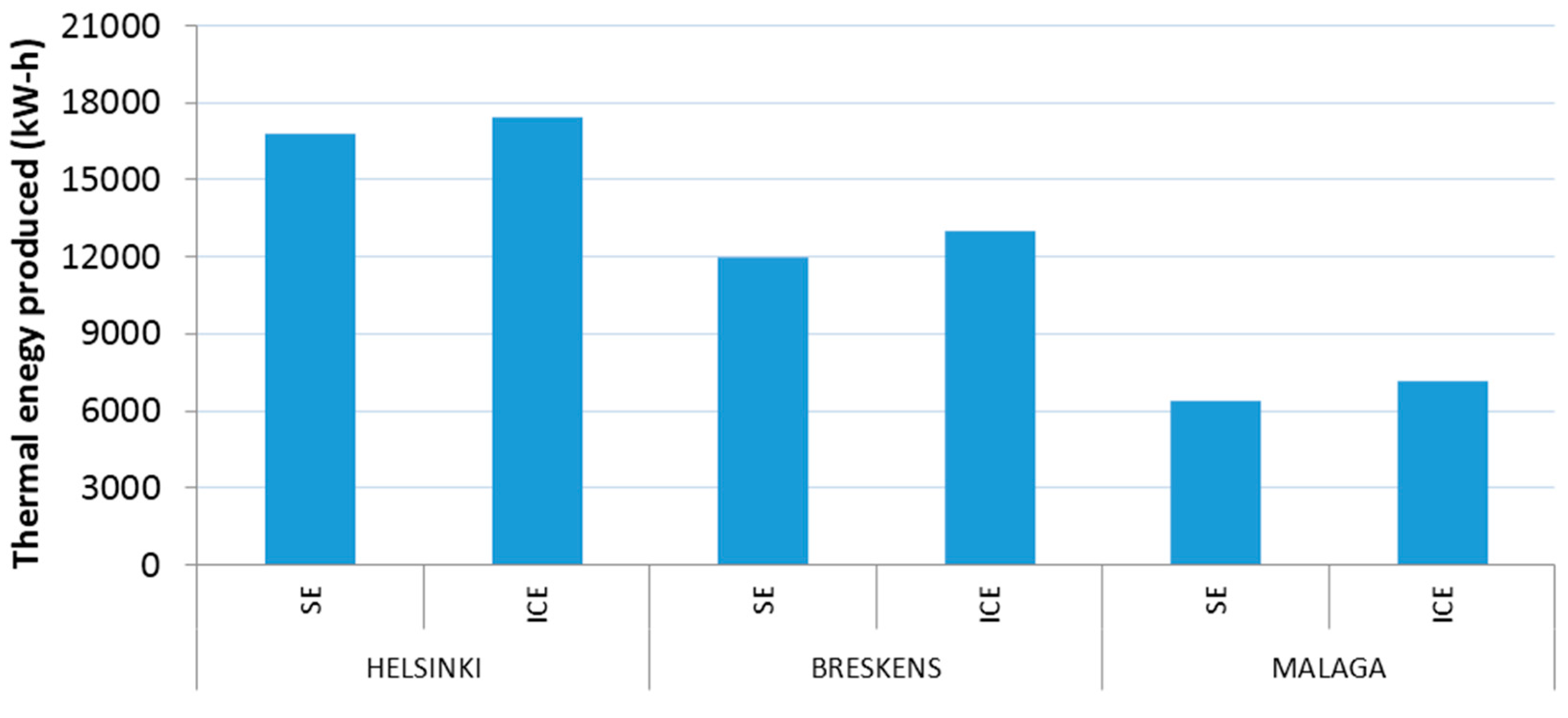
3.3. Performance of the ICE-Based Micro-CHP Unit

Results are presented as a comparison with an SE based micro-CHP system, with similar outputs [38]. Annual thermal performance is shown in Figure 6. Figure 7 shows monthly electricity production and Figure 8 depicts annual percentage of electrical coverage.
Heat production is very similar using SE and ICE because the simulations are performed FTL. These results are predictable, because both systems are suitable for the application under study, as heat demands were previously calculated. The slight differences in heat production results are due to the small differences in heating power of the two systems.
Annual electrical production and coverage are very similar too, although it never reaches 100%. Nevertheless, the most important difference in electrical production occurs during warm months (May to September). This difference is more remarkable in warmer climates (Malaga) where the thermal load is lower. Under this condition ICE supplies less electricity because of its lower electric/thermal power ratio: 13% compared to 15% with SE. This small difference is also the reason behind the higher number of hours with full battery using SE. Figure 9 shows the number of hours when the batteries of the systems are full. This time is significantly higher in the colder climate (Helsinki), where electricity production is also higher.

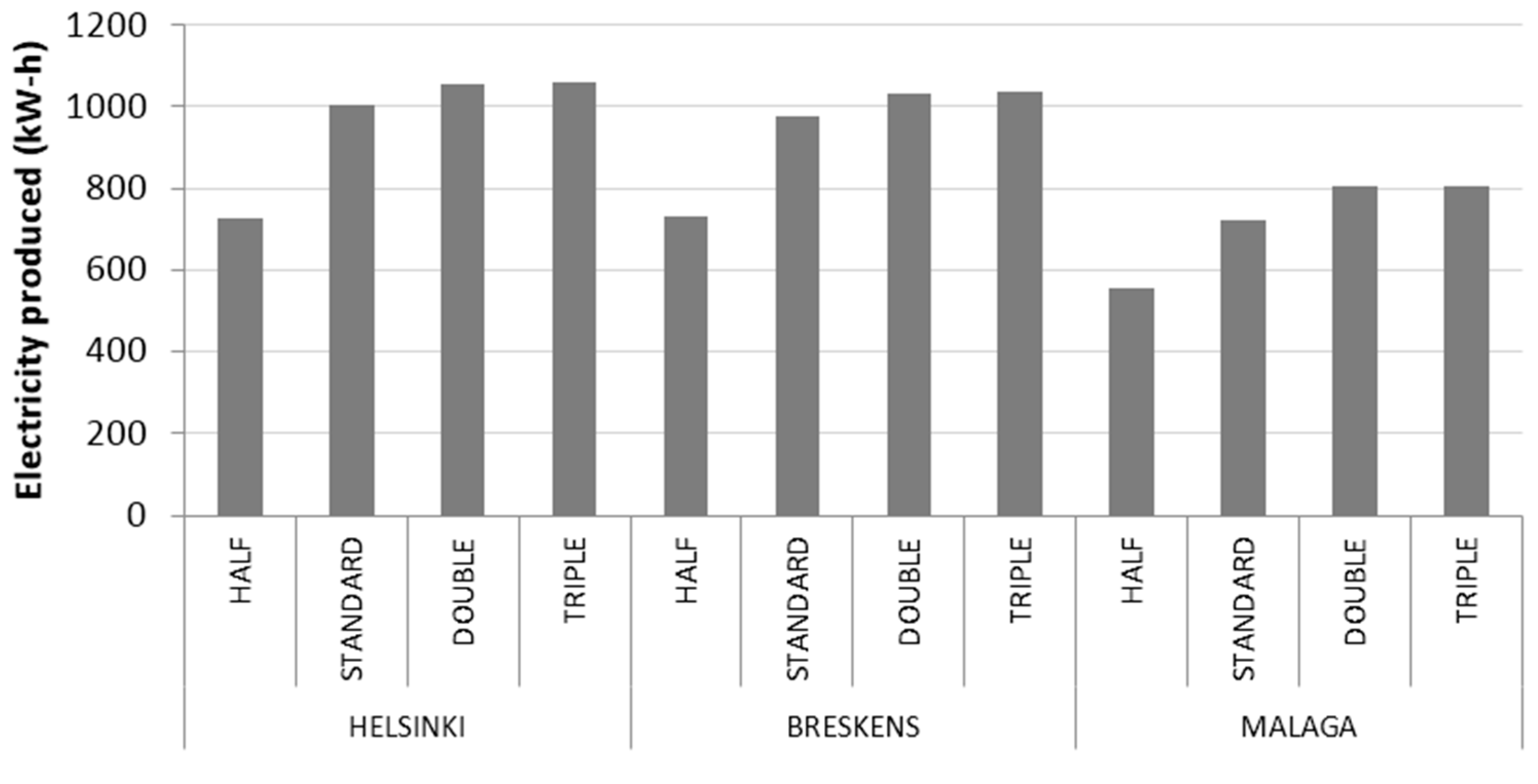
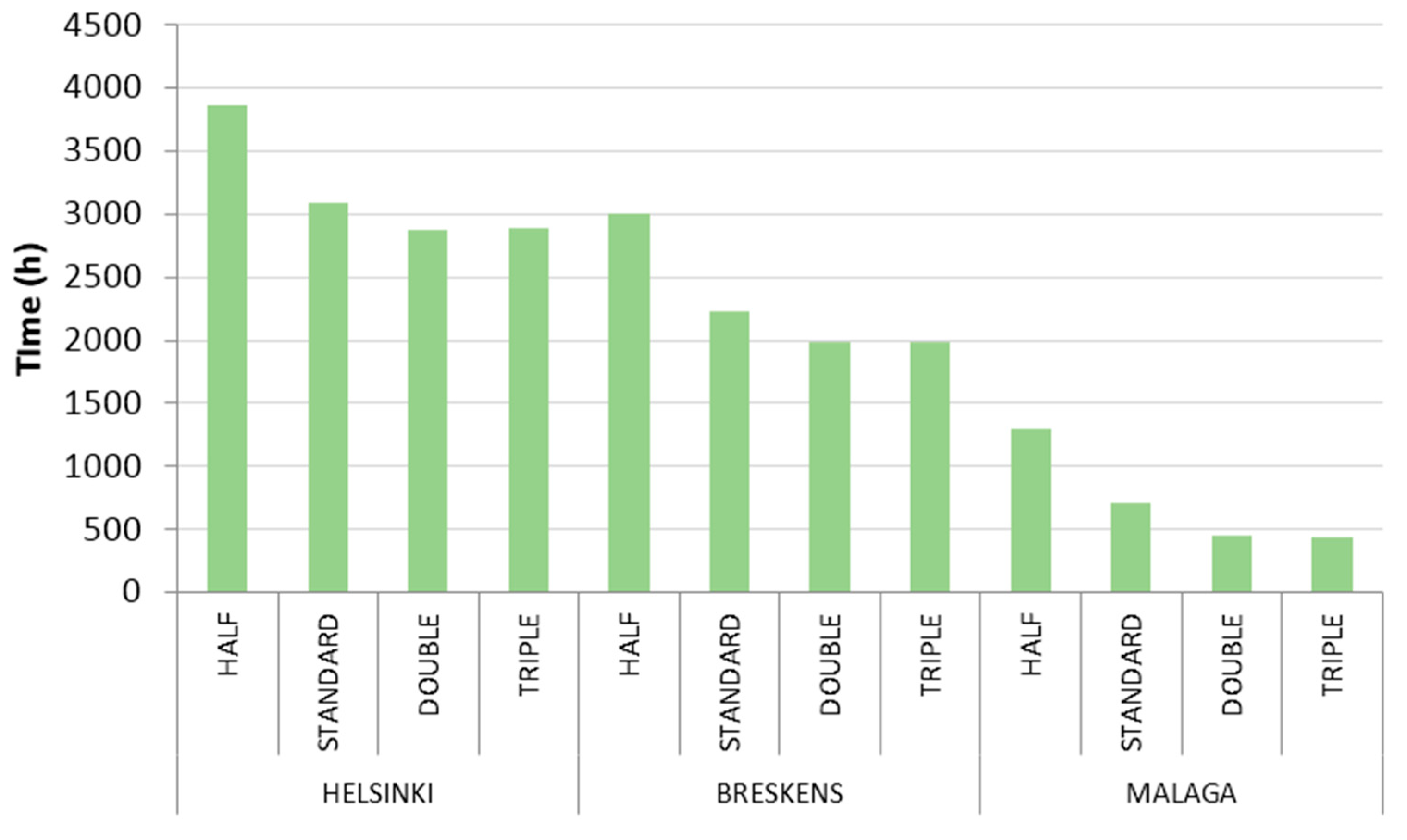
3.4. Sensitivity Analysis

A sensitivity analysis was performed using different sizes of the battery bank with the ICE system. The battery bank of the original study was set to 24 V/100 Ah, and hereinafter it is the designated as the “Standard” size. Three different scenarios, where the battery bank size was modified, were compared. One of the scenarios was equipped with “Half” capacity, another one with “Double” size, and the last one with “Triple” size.
Thermal energy production is very similar in all the scenarios, due to the FTL strategy, so it is not presented. Electrical energy production is lower when the battery bank is half size, because the electrical energy produced when the batteries are full is dedicated to producing heat. The correlation between electrical energy production and battery size can be seen in Figure 10 and Figure 11. When battery size increases, also it increases the amount of electrical energy produced and the percentage of coverage attended. Anyway, there is not a big difference between doubling and tripling the battery size. As it is observed in the results, battery size increase has a limit. Above this limit there are no differences in the system performance. This limit does not depend on how much warmer or cooler the climate is, but rather it depends on the electrical load as the daily consumption profile remains the same during the whole simulation.

4. Conclusions

In this research an ICE-based micro-CHP unit was developed and tested. The unit was configured to cover the thermal demand of different European locations. Thermal and electrical power was measured using three different engine speeds, and outcomes at 2900 rpm were chosen to carry out the simulations.
System performance results were compared to SE results and both of them are quite similar. The main difference was found in warmer locations during the warmer season, when the electrical demand is less covered using the ICE unit. This difference is readily explained considering the smaller electrical/thermal production ratio of the ICE system compared to the SE one.
A sensitivity analysis was done, comparing the results of the standard size of the battery bank with the results obtained in three different scenarios with three different battery sizes: half, double and triple. Double size was optimum with this system as there no improvement was seen by tripling its size, independently of the location climate. The optimal battery size is a function of the type of electrical load profile. With a double size battery bank, the electricity production increases 4.9% in Helsinki, 5.9% in Breskens, and 11.1% in Malaga.
One of the aims for the improvement of the ICE-based micro-CHP system was to increase the electrical/thermal ratio, using a more powerful alternator. Future research will be focused on studying different electrical consumption profiles with different battery sizes to find a correlation between these two factors.

Acknowledgments

This project has been supported by funding from the Center for Industrial Technological Development (CDTI) through Interconnecta program (grant number: IDI-20111660), Ministry of Economy and Competitiveness of Spain.

Author Contributions

All authors contributed to this work. Guillermo Rey is the main author of this work.

Conflicts of Interest

The authors declare no conflict of interest.

Abbreviations

The following abbreviations are used in this manuscript:
ICEInternal Combustion Engine
micro-CHPmicro Combined Heating and Power
SEStirling Engine
TESThermal Energy Storage
FELFollowing Electric Load
FTLFollowing Thermal Load
PVCPolyvinyl chloride
DHWDomestic Hot Water
TMYTypical Meteorological Year
NCARNational Center for Atmospheric Research
SSTSea Surface Temperature
netCFDnetwork Common Data Format

References

  1. Chesi, A.; Ferrara, G.; Ferrari, L.; Magnani, S.; Tarani, F. Influence of the heat storage size on the plant performance in a Smart User case study. Appl. Energy 2013, 112, 1454–1465. [Google Scholar] [CrossRef]
  2. Barbieri, E.S.; Melino, F.; Morini, M. Influence of the thermal energy storage on the profitability of micro-CHP systems for residential building applications. Appl. Energy 2012, 97, 714–722. [Google Scholar] [CrossRef]
  3. Budzianowski, W.M. Negative net CO2 emissions from oxy-decarbonization of biogas to H2. Int. J. Chem. React. Eng. 2010, 8, 1542–6580. [Google Scholar] [CrossRef]
  4. Milewski, J.; Szabłowski, L.; Kuta, J. Control strategy for an Internal combustion engine fuelled by natural gas operating in distributed generation. Energy Procedia 2012, 14, 1478–1483. [Google Scholar] [CrossRef]
  5. Williams, M.C.; Strakey, J.P.; Singhal, S.C. U.S. distributed generation fuel cell program. J. Power Sources 2004, 131, 79–85. [Google Scholar] [CrossRef]
  6. Onovwiona, H.I.; Ugursal, V.I. Residential cogeneration systems: Review of the current technology. Renew. Sustain. Energy Rev. 2006, 10, 389–431. [Google Scholar] [CrossRef]
  7. Peacock, A.D.; Newborough, M. Impact of micro-combined heat-and-power systems on energy flows in the UK electricity supply industry. Energy 2006, 31, 1804–1818. [Google Scholar] [CrossRef]
  8. Kuhn, V.; Klemeš, J.; Bulatov, I. MicroCHP: Overview of selected technologies, products and field test results. Appl. Therm. Eng. 2008, 28, 2039–2048. [Google Scholar] [CrossRef]
  9. Roselli, C.; Sasso, M.; Sibilio, S.; Tzscheutschler, P. Experimental analysis of microcogenerators based on different prime movers. Energy Build. 2011, 43, 796–804. [Google Scholar] [CrossRef]
  10. Ghasemi, A.; Asrari, A.; Zarif, M.; Abdelwahed, S. Techno-economic analysis of stand-alone hybrid photovoltaic–diesel–battery systems for rural electrification in eastern part of Iran—A step toward sustainable rural development. Renew. Sustain. Energy Rev. 2013, 28, 456–462. [Google Scholar] [CrossRef]
  11. Bernal-Agustıín, J.L.; Dufo-López, R. Simulation and optimization of stand-alone hybrid renewable energy systems. Renew. Sustain. Energy Rev. 2009, 13, 2111–2118. [Google Scholar] [CrossRef]
  12. Karmacharya, S.; Putrus, G.; Underwood, C.P.; Mahkamov, K.; McDonald, S.; Alexakis, A. Simulation of energy use in buildings with multiple micro generators. Appl. Therm. Eng. 2014, 62, 581–592. [Google Scholar] [CrossRef]
  13. Brandoni, C.; Renzi, M.; Caresana, F.; Polonara, F. Simulation of hybrid renewable microgeneration systems for variable electricity prices. Appl. Therm. Eng. 2014, 71, 667–676. [Google Scholar] [CrossRef]
  14. Monteiro, E.; Moreira, N.A.; Ferreira, S. Planning of micro-combined heat and power system in the Portuguese scenario. Appl. Energy 2009, 86, 290–298. [Google Scholar] [CrossRef]
  15. Campos, A.C.; Erkoreka, A.; Escudero, K.M.; Sala, J.M. Feasibility of small-scale gas engine-based residential cogeneration in Spain. Energy Policy 2011, 39, 3813–3821. [Google Scholar] [CrossRef]
  16. Rosato, A.; Sibilio, S.; Ciampi, G. Energy, environmental and economic dynamic performance assessment of different micro-cogeneration systems in a residential application. Appl. Therm. Eng. 2013, 59, 599–617. [Google Scholar] [CrossRef]
  17. Xu, H.; Dang, Z.; Bai, B.F. Analysis of a 1 kW residential combined heating and power system based on solid oxide fuel cell. Appl. Therm. Eng. 2013, 50, 1101–1110. [Google Scholar] [CrossRef]
  18. Wang, H.; Jiao, W.; Lahdelma, R.; Zhu, C.; Zou, P. Stochastic multicriteria acceptability analysis for evaluation of combined heat and power units. Energies 2015, 8, 59–78. [Google Scholar] [CrossRef]
  19. Entchev, E.; Yang, L.; Szadkowski, F.; Armstrong, M.; Swinton, M. Application of hybrid micro-cogeneration system—Thermal and power energy solutions for Canadian residences. Energy Build. 2013, 60, 345–354. [Google Scholar] [CrossRef]
  20. Ehyaei, M.A.; Ahmadi, P.; Atabi, F.; Heibati, M.R.; Khorshidvand, M. Feasibility study of applying internal combustion engines in residential buildings by exergy, economic and environmental analysis. Energy Build. 2012, 55, 405–413. [Google Scholar] [CrossRef]
  21. Van Bael, J.; Six, D.; Vanhoudt, D.; Desmedt, J. Feasibility and potential of micro combined heat and power in Flanders. In Proceedings of the 2nd International Conference on Microgeneration and Related Technologies (MICROGEN II), Glasgow, UK, 4–6 April 2011.
  22. Alanne, K.; Söderholm, N.; Sirén, K.; Beausoleil-Morrison, I. Techno-economic assessment and optimization of Stirling engine micro-cogeneration systems in residential buildings. Energy Convers. Manag. 2010, 51, 2635–2646. [Google Scholar] [CrossRef]
  23. Magri, G.; Di Perna, C.; Serenelli, G. Analysis of electric and thermal seasonal performances of a residential microCHP unit. Appl. Therm. Eng. 2012, 36, 193–201. [Google Scholar] [CrossRef]
  24. Barbieri, E.S.; Spina, P.R.; Venturini, M. Analysis of innovative micro-CHP systems to meet household energy demands. Appl. Energy 2012, 97, 723–733. [Google Scholar] [CrossRef]
  25. Comodi, G.; Cioccolanti, L.; Renzi, M. Modelling the Italian household sector at the municipal scale: Micro-CHP, renewables and energy efficiency. Energy 2014, 68, 92–103. [Google Scholar] [CrossRef]
  26. Ren, H.; Gao, W.; Zhou, W.; Nakagami, K. Multi-criteria evaluation for the optimal adoption of distributed residential energy systems in Japan. Energy Policy 2009, 37, 5484–5493. [Google Scholar] [CrossRef]
  27. Pagliarini, G.; Rainieri, S. Modeling of a thermal energy storage system coupled with combined heat and power generation for the heating requirements of a university campus. Appl. Therm. Eng. 2010, 30, 1255–1261. [Google Scholar] [CrossRef]
  28. Campos Celador, A.; Odriozola, M.; Sala, J.M. Implications of the modelling of stratified hot water storage tanks in the simulation of CHP plants. Energy Convers. Manag. 2011, 52, 3018–3026. [Google Scholar] [CrossRef]
  29. Smith, A.D.; Mago, P.J.; Fumo, N. Benefits of thermal energy storage option combined with CHP system for different commercial building types. Sustain. Energy Technol. Assess. 2013, 1, 3–12. [Google Scholar] [CrossRef]
  30. Lozano, M.A.; Ramos, J.C.; Serra, L.M. Cost optimization of the design of CHCP (combined heat, cooling and power) systems under legal constraints. Energy 2010, 35, 794–805. [Google Scholar] [CrossRef]
  31. TeymouriHamzehkolaei, F.; Sattari, S. Technical and economic feasibility study of using Micro CHP in the different climate zones of Iran. Energy 2011, 36, 4790–4798. [Google Scholar] [CrossRef]
  32. Stathopoulos, P.; Paschereit, C.O. Retrofitting micro gas turbines for wet operation. A way to increase operational flexibility in distributed CHP plants. Appl. Energy 2015, 154, 438–446. [Google Scholar] [CrossRef]
  33. Merkel, E.; McKenna, R.; Fichtner, W. Optimisation of the capacity and the dispatch of decentralised micro-CHP systems: A case study for the UK. Appl. Energy 2015, 140, 120–134. [Google Scholar] [CrossRef]
  34. Ren, H.; Gao, W. Economic and environmental evaluation of micro CHP systems with different operating modes for residential buildings in Japan. Energy Build. 2010, 42, 853–861. [Google Scholar] [CrossRef]
  35. Camporeale, S.M.; Fortunato, B.; Torresi, M.; Turi, F.; Pantaleo, A.M.; Pellerano, A. Part load performance and operating strategies of a natural gas—biomass dual fueled microturbine for combined heat and power generation. J. Eng. Gas Turbines Power 2015, 137. [Google Scholar] [CrossRef]
  36. Mago, P.J.; Fumo, N.; Chamra, L.M. Performance analysis of CCHP and CHP systems operating following the thermal and electric load. Int. J. Energy Res. 2009, 33, 852–864. [Google Scholar] [CrossRef]
  37. Ulloa, C.; Porteiro, J.; Eguía, P.; Pousada-Carballo, J.M. Application model for a Stirling Engine micro-generation system in caravans in different European locations. Energies 2013, 6, 717–732. [Google Scholar] [CrossRef]
  38. Ulloa, C.; Eguía, P.; Míguez, J.L.; Porteiro, J.; Pousada-Carballo, J.M.; Cacabelos, A. Feasibility of using a Stirling engine-based micro-CHP to provide heat and electricity to a recreational sailing boat in different European ports. Appl. Therm. Eng. 2013, 59, 414–424. [Google Scholar] [CrossRef]
  39. Grljusic, M.; Medica, V.; Radica, G. Calculation of efficiencies of a ship power plant operating with waste heat recovery through combined heat and power production. Energies 2015, 8, 4273–4299. [Google Scholar] [CrossRef]
  40. Grljusic, M.; Medica, V.; Racic, N. Thermodynamic analysis of a ship power plant operating with waste heat recovery through combined heat and power production. Energies 2014, 7, 7368–7394. [Google Scholar] [CrossRef]
  41. Zago, M.; Casalegno, A.; Marchesi, R.; Rinaldi, F. Efficiency analysis of independent and centralized heating systems for residential buildings in northern Italy. Energies 2011, 4, 2115–2131. [Google Scholar] [CrossRef]
  42. Campos-Celador, A.; Pérez-Iribarren, E.; Sala, J.M.; Portillo-Valdés, L.A. Thermoeconomic analysis of a micro-CHP installation in a tertiary sector building through dynamic simulation. Energy 2012, 45, 228–236. [Google Scholar] [CrossRef]
  43. González-Pino, I.; Campos-Celador, A.; Pérez-Iribarren, E.; Terés-Zubiaga, J. Parametric study of the operational and economic feasibility of Stirling micro-cogeneration devices in Spain. Appl. Therm. Eng. 2014, 71, 821–829. [Google Scholar] [CrossRef]
  44. Battista, G.; Evangelisti, L.; Guattari, C.; Basilicata, C.; Vollaro, R.L. Buildings energy efficiency: Interventions analysis under a Smart Cities approach. Sustainability 2014, 6, 4694–4705. [Google Scholar] [CrossRef]
  45. Meteonorm Web Site. Available online: http://meteonorm.com/ (accessed on 15 October 2015).
  46. The National Center for Atmospheric Research Web Site. Available online: http://ncar.ucar.edu/ (accessed on 15 October 2015).
  47. Ebrahimpour, A.; Maerefat, M. A method for generation of typical meteorological year. Energy Convers. Manag. 2010, 51, 410–417. [Google Scholar] [CrossRef]
Figure 1. Some heat recovery components: (a) three way valve of the engine coolant circuit; (b) flowmeter in the cooling circuit; (c) storage tank with the tap water circuit
Energies 09 00239 g001
Figure 2. ICE-based micro CHP unit layout.
Energies 09 00239 g002
Figure 3. DHW and electrical demands scheduled in TRNSYS.
Energies 09 00239 g003
Figure 4. Ship wetwalls and drywalls [38].
Energies 09 00239 g004
Figure 5. Coolant temperature: (a) 2100 rpm; (b) 2900 rpm; (c) 3500 rpm.
Energies 09 00239 g005
Figure 6. Annual thermal production in kW-h.
Energies 09 00239 g006
Figure 7. Monthly electricity production in kW-h.
Energies 09 00239 g007
Figure 8. Annual electrical coverage.
Energies 09 00239 g008
Figure 9. Annual time in hours with battery full.
Energies 09 00239 g009
Figure 10. Annual electricity production in kW-h for different battery sizes.
Energies 09 00239 g010
Figure 11. Annual time in hours with full battery for different battery sizes.
Energies 09 00239 g011
Table 1. Compositions and thermal properties of the walls [38].
Envelope LayersWetwallDrywall
FiberglassOuter FiberglassPolyvinyl chloride (PVC)Inner Fiberglass
Thickness [mm]13102010
Thermal Conductivity [W/m·K]0.040.040.230.04
Capacity [kJ/kg·K]0.840.8410.84
Density [kg/m3]1212150012
Table 2. Electric and thermal load power under steady state conditions.
Engine Speed (rpm)Electric Power (kW)Heating Power (kW)
21000.5562.382
29000.6104.747
35000.6535.414
Table 3. Peak heat demand with time and climate conditions.
ClimateCityPeak Heat Demand (kW)Month of Peak Heat DemandDay of Peak Heat DemandTime of Peak Heat DemandAir Temperature (°C)SST (°C)
Northern European AtlanticHELSINKI4.352158:06−21.90.7
Southern European AtlanticBRESKENS2.6111221:06−4.57.4
MediterraneanMALAGA1.721129:004.015.5

