Article

A Dual-Consequent-Pole Vernier Memory Machine

1
Engineering Research Center for Motion Control of Ministry of Education, Southeast University, Nanjing 210096, China
2
Department of Electronic and Electrical Engineering, University of Sheffield, Sheffield S1 3JD, UK
*
Author to whom correspondence should be addressed.
These authors contributed equally to this work.
Energies 2016, 9(3), 134; https://doi.org/10.3390/en9030134
Submission received: 14 December 2015 / Revised: 14 February 2016 / Accepted: 22 February 2016 / Published: 26 February 2016

Abstract

:
This paper proposes a novel dual-consequent-pole Vernier memory machine (DCP-VMM) featuring alternatively arranged NdFeB and low coercive-force (LCF) magnet poles on the rotating and stationary sides, respectively. Due to the presence of LCF magnets that can be repetitively magnetized or demagnetized via a simple current pulse, the extra-high torque density at low-speed, and excellent high-efficient high-speed flux-weakening performance can be simultaneously realized. The configuration and operating principle, as well as the design considerations of the proposed machine are introduced, respectively. The finite element method (FEM) coupled with a nonlinear analytical hysteresis model for LCF magnets is employed to investigate the electromagnetic performance of the machine, which verifies the effectiveness of machine design and the feasibility as a competent candidate for automotive applications.

1. Introduction

Low-speed direct-drive gearless machines are highly desirable for electric vehicle/hybrid electric vehicle (EV/HEV) propulsion due to the elimination of the associated gear wear, friction loss, and oil maintenance as well as audible noise problems [1,2,3,4]. Conventional gearless direct-drive permanent magnet (PM) machines generally suffer from heavy weight, structural bulkiness, and lubrication problems. Several novel machine topologies, e.g., dual mechanical-port [5] and axial [6] or transverse field [7] machines have been developed to resolve the aforementioned drawbacks. Nonetheless, the complicated mechanical structures and low reliability appear to be the major obstacle for their industrial popularization.
Due to the “magnetic-gearing” effect, the recently emerging magnetically geared machines (MGMs) [5,8,9,10,11,12,13,14,15,16] have been widely researched and recognized as a promising solution favorable for traction applications. Since abundant asynchronous field harmonics are excited by modulating iron poles, which are directly involved in torque transmission. MGMs have the distinct synergies of magnetic gears and PM machines, i.e. high torque with volume miniaturization, high efficiency and mechanical compactness [8,9]. Amongst MGM topologies, Vernier machines (VMs) [11,12,13,14,15,16] with simpler mechanical assembly are preferable for safety-critical applications compared to MGMs with multiple air-gaps. Various VM topologies with magnets located on either the rotor [11,12,13] or stator side [14], in which the stator or rotor teeth serve as flux modulators to yield plentiful working harmonics arrays contributing to torque production, have been extensively investigated [16]. The concept of dual sets of magnets was incorporated into the VM configuration to deliver much higher torque without increasing the manufacturability problems [15]. However, the resultant severe magnetic saturation incurs iron loss issues unexpected for high-speed cruising operation in electric vehicles. Meanwhile, hybrid excitation was introduced to VMs so as to adjust the air-gap flux and extend constant-power operating range, as well as alleviate inverter requirements [17], but continuous excitation copper loss is inevitably incurred, which will reduce the operating efficiency. On the other hand, memory machines [10,18,19,20,21,22,23,24,25,26] equipped with either single low-coercive force (LCF) or hybrid magnets were extensively investigated due to the elimination of the associated excitation loss during the flux adjustment. As a result, they can readily perform high efficiency operation within a wide range of speeds and loads. Very recently, the concept of “memory machines” is incorporated into VMs, and the corresponding topologies hybridizing low coercive force (LCF) magnets and NdFeB PMs were proposed and investigated [25]. Nevertheless, LCF PMs are magnetically exposed to the armature reaction fields, which potentially causes a demagnetization risk.
This paper proposes a novel dual-consequent-pole Vernier memory machine (DCP-VMM) having alternatively arranged NdFeB and LCF magnet poles on the rotating and stationary sides, respectively. It comprises only one rotor and one stator, which will be helpful to facilitating the mechanical manufacturing, and hence increasing the industrial practicability. Due to the presence of LCF magnets that can be repeatedly magnetized or demagnetized via a current pulse, the high torque density at low-speed can be readily realized when the magnetized directions of LCF magnets are identical with those of NdFeB PMs. In that case, the two sets of magnets are synthetically engaged to perform dual flux modulation effects. On the other hand, the excellent high-speed flux-weakening performance without excitation loss can be realized when the LCF magnets are reversely demagnetized to weaken the flux produced by NdFeB PMs. The topology and operating principle, as well as the design considerations of the proposed DCP-VMM are introduced. The electromagnetic performance is analyzed by means of finite element method (FEM) coupled with an analytical hysteresis model [26] for LCF PMs, which confirms the feasibility of machine design.

2. Machine Topology and Operating Principle

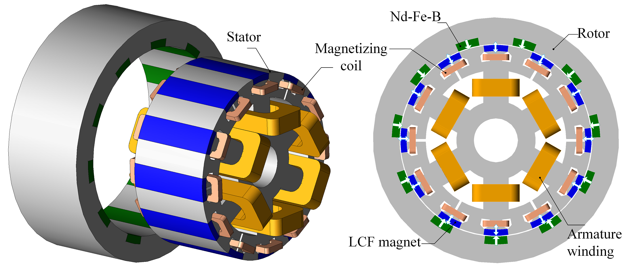
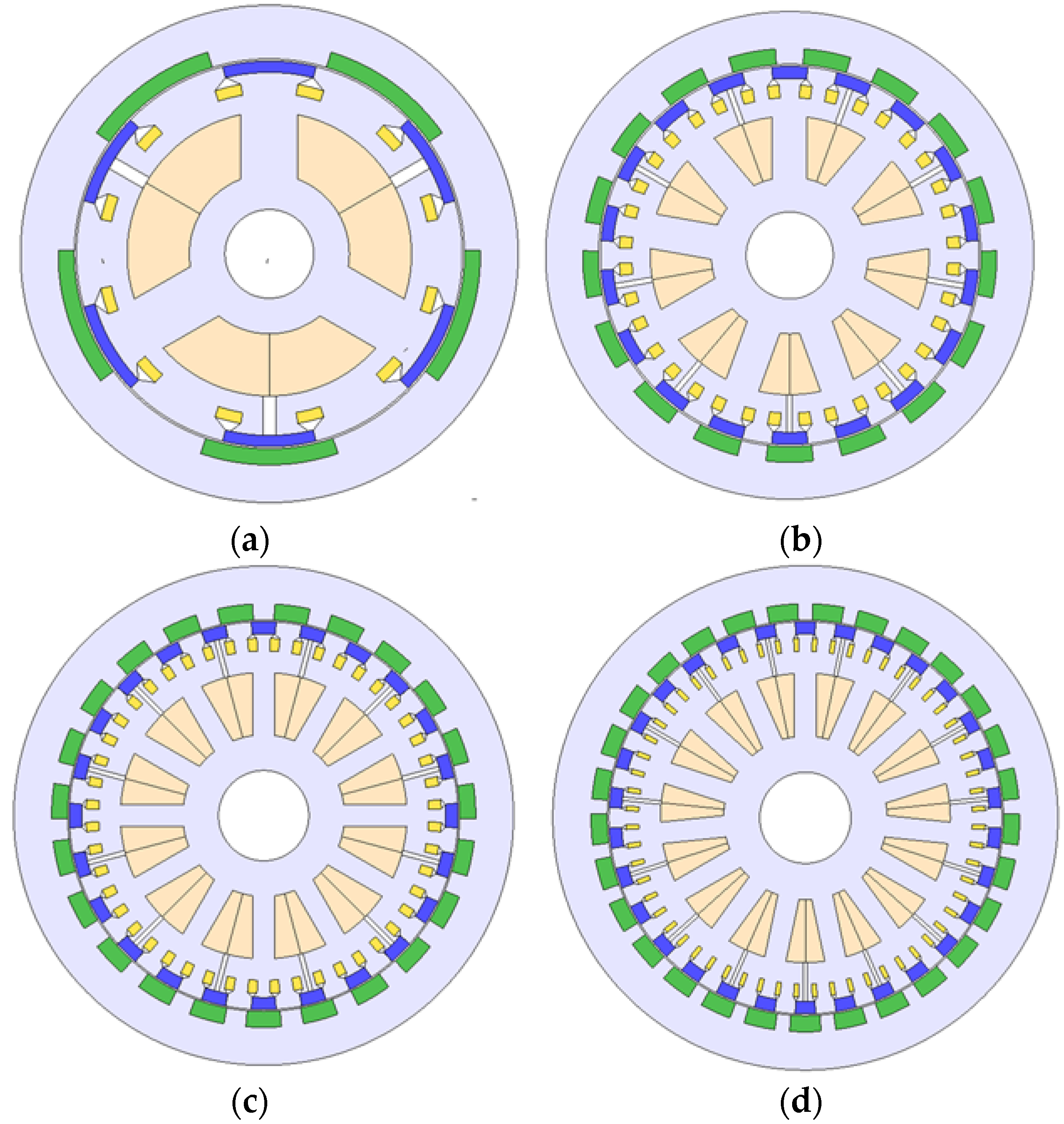
2.1. Machine Configuration

Figure 1 illustrates the configuration of the proposed DCP-VMM, which is characterized by a combination of two individual VMs featuring magnets on the rotating and stationary sides, respectively. The machine comprises only one external rotor and one multi-tooth inner stator, which facilitates in-wheel driving application to EVs, and hence the mechanical manufacturability as well as space utilization ratio are improved. The NdFeB magnets are mounted on the external rotor, which function as a main contributor to the main air-gap flux. The radially magnetized LCF PMs are alternately buried in air space between adjacent modulating iron poles, and the magnetizing coils are wound beneath the LCF magnet poles, which empowers current pulsation to enable the magnetization state variations of the corresponding LCF magnets.

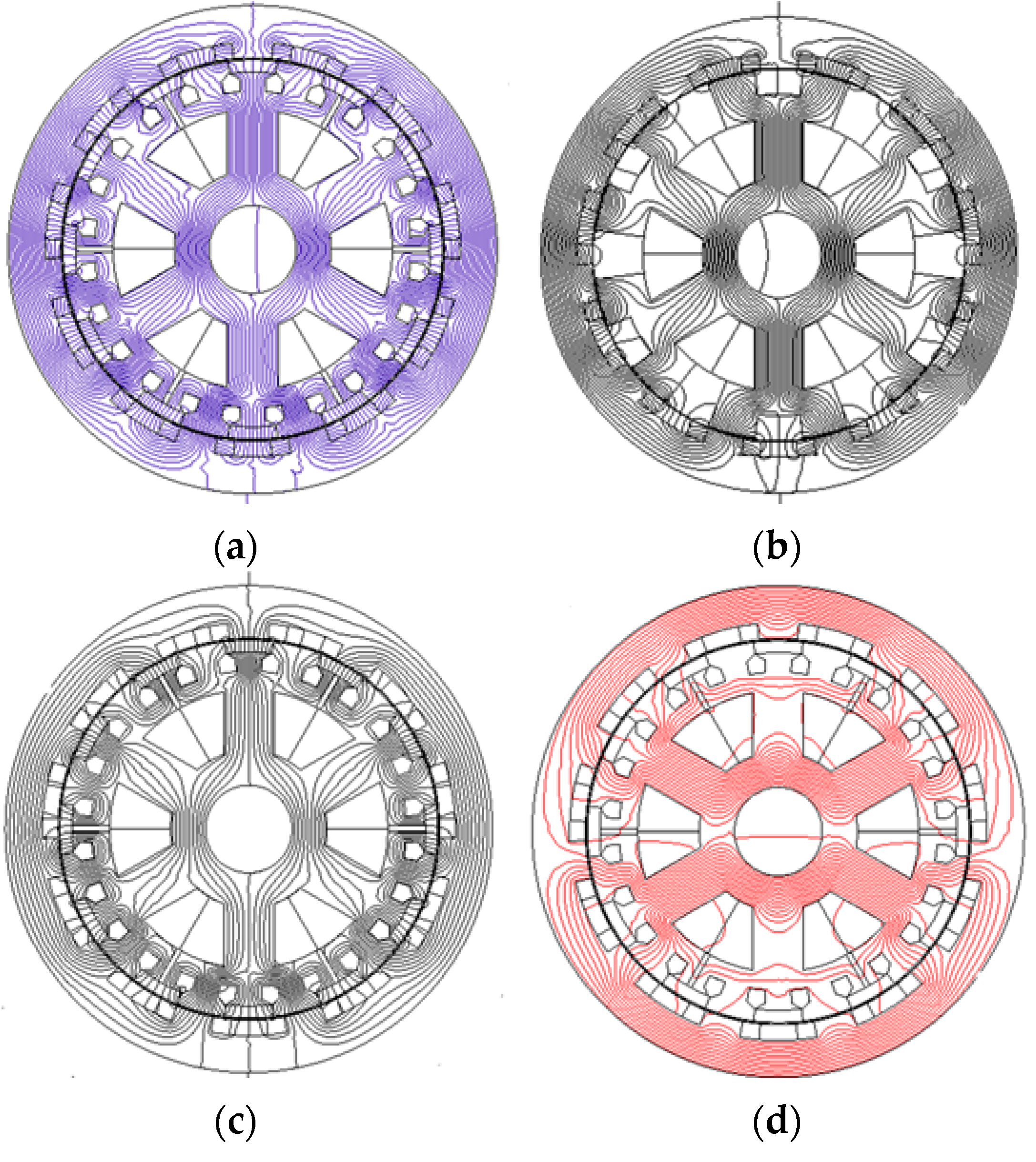
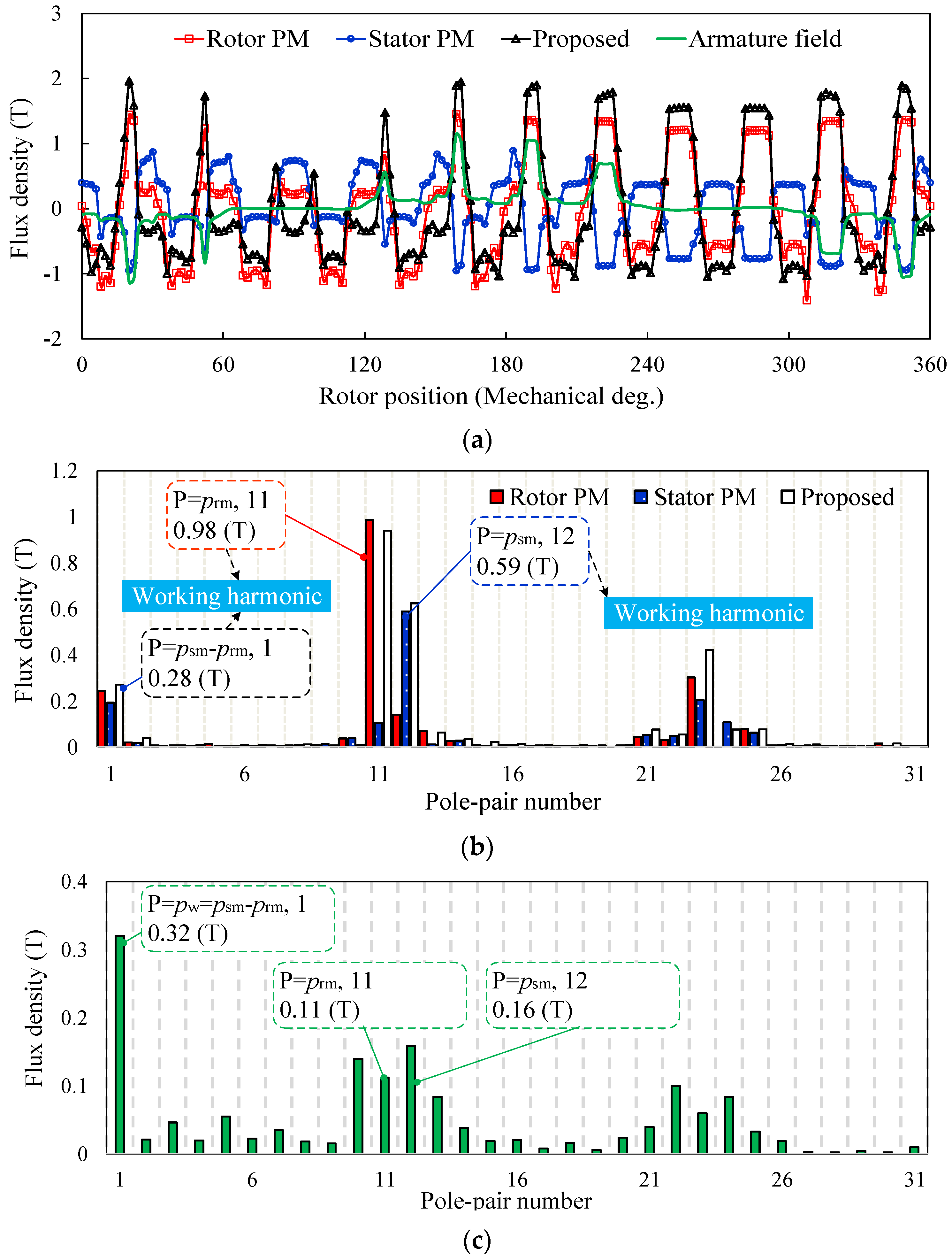
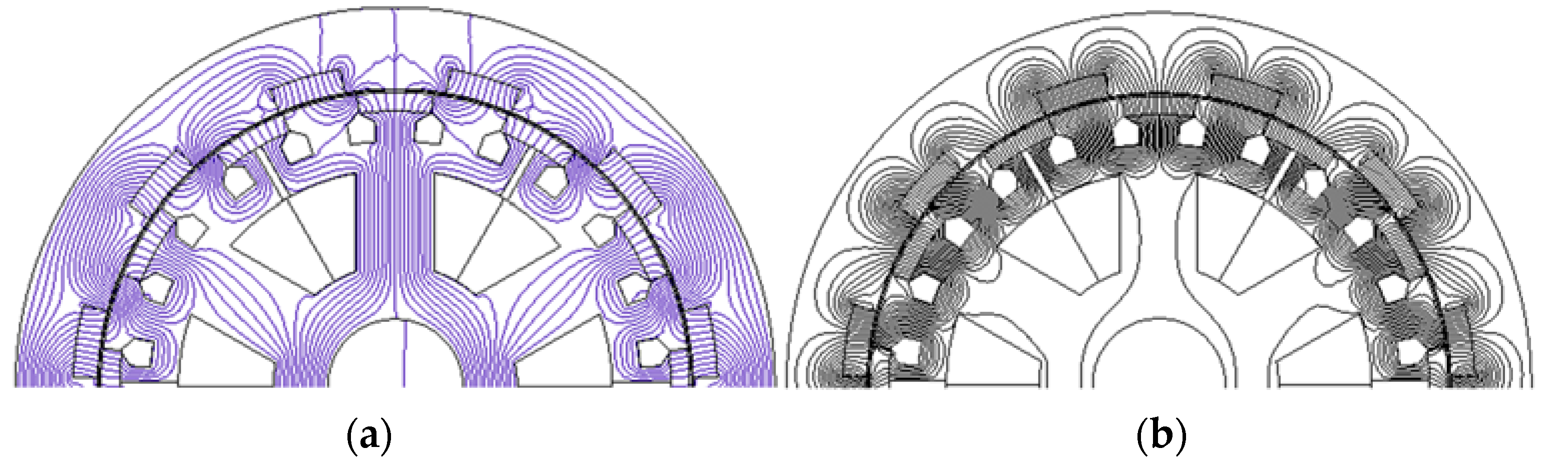
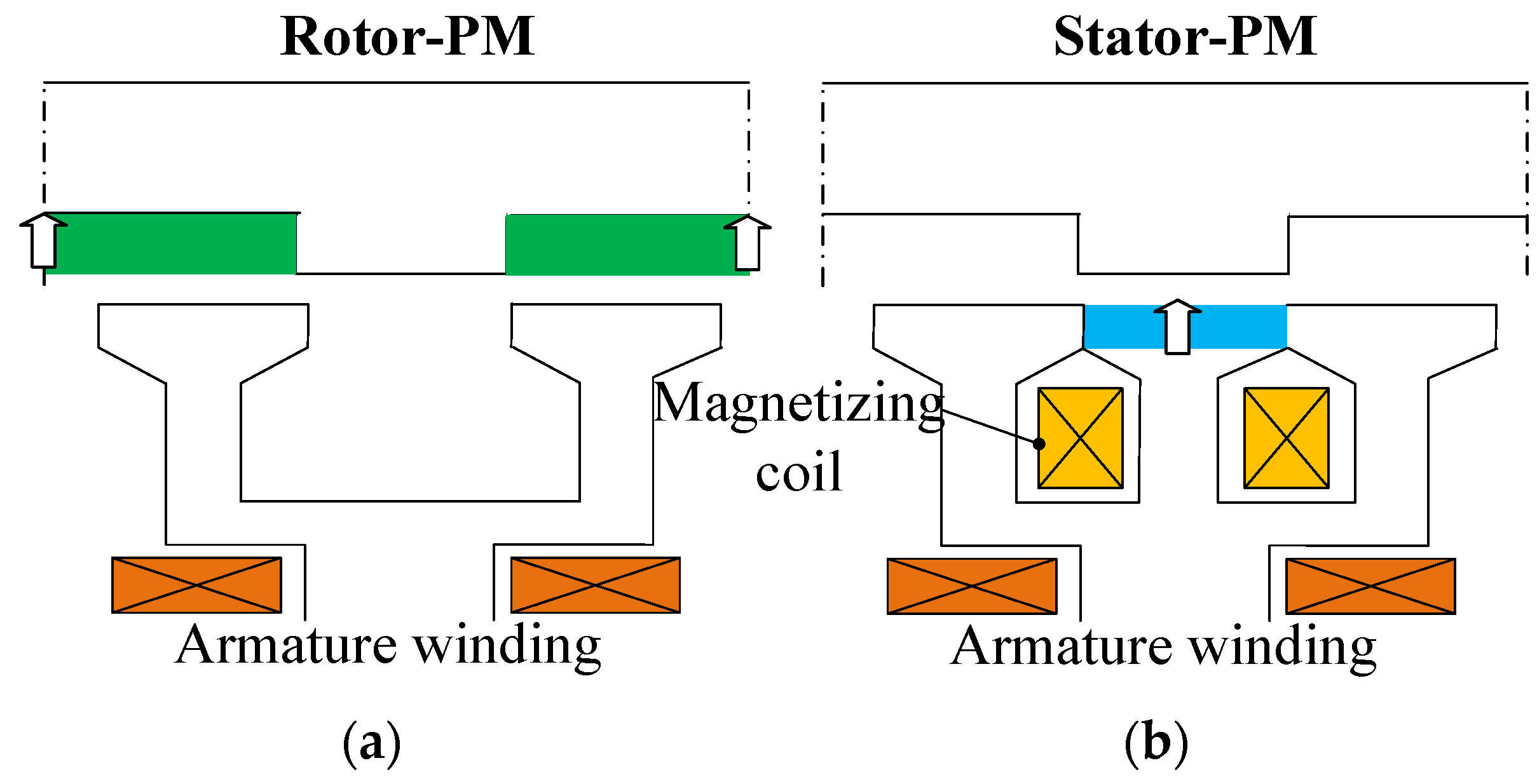
2.2. Dual Magnetic-Gearing Effect

Magnetic-gearing effect refers to the abundant production of field harmonics due to the non-uniform magnetic field paths, which directly engage in the electromechanical energy conversion process. Generally, the pole pairs numbers (PPNs) of a series of air-gap flux harmonics modulated by the modulators can be analytically expressed as [16]:
P P N i , j = | ( 2 i 1 ) p r m + j p s m |
where i is a positive integer (1, 2, 3,…), j is an integer (0, ±1, ±2,…), prm and psm represent the rotor magnet PPN and modulator number (equals stator magnet PPN); and the corresponding high-to-low gear ratio Gr is governed by:
G r = | ( 2 i 1 ) p r m + j p s m ( 2 i 1 ) p r m |
It can be deduced that the highest space harmonic component is obtainable when i = 1 and j = −1. Since DCP-VMM can be geometrically considered as a combination of rotor- and stator-PM excited VMs as illustrated in Figure 2, the operating principle can be understood from the resultant magnetic-gearing effects arising from dual magnet excitations. From the rotor side, based on Equation (2), the dominant air-gap flux density resulted by PM magneto-motive force (MMF) modulated by the multi stator poles can be approximated as:
B δ = F m Λ t o t a l 4 B r h r m μ 0 μ r Λ 0 cos [ p r m ( θ ω r m t θ 0 ) ]            + 2 B r h r m μ 0 μ r Λ 1 cos ( ( p r m p s m ) ( θ p r m ( ω r m t θ 0 ) p r m p s m ) )
where Fm, Br, μ0, μr, hrm, and Λtotal signify the PM MMF, recoil flux density, vacuum permeability, PM relative permeability, rotor PM thickness and total air-gap permeance, respectively; ωrm, θ, and θ0 denote the rotating angular speed of rotor, the circumferential position and initial position, respectively. It is observable that the first term refers to the fundamental component similar to its conventional PM counterpart, while the second term can be considered as the modulated one. The steady torque can be yielded from the synchronization of the modulated low-order harmonic component with high velocity and its corresponding coil MMF one, as long as the PPN and angular speed of working spatial harmonic pw1 and ωw1 satisfy:
p w 1 = | p s m p r m |
ω w 1 = p r m p s m p r m ω r = G r ω r m
where the minus sign indicates that this modulated harmonic rotates conversely with the fundamental one. Thus, the second term in (1), referred to “non-goodness” behaviors in conventional PM machines which produce torque ripples, can effectively contribute to torque transmission owing to the vernier structure. From the stator side, the stationary PM fields (PPN = psm) are modulated by the rotating poles with (PPN = prm), based on the similar derivation, the angular speed of working spatial harmonic ωw2 can be analogously given by [16]:
ω w 2 = p r m p r m p s m ω r = G r ω r m
It can be deduced from Equations (5) and (6) that the working harmonics of the individual case share the same PPN and rotation speed, and thus the stable torque transmission can be achieved as the PPN of stator windings equals ωw1 or ωw2. As a result, the effective coupling between the armature fields and magnetic fields excited by either rotor or stator magnets can be synthesized, i.e., the dual magnetic-gearing effects occur. The field distributions excited by either sole or hybrid magnets, as well as the armature reaction fields are shown in Figure 3. Obviously, the hybrid, stator and rotor-PM machines share the basically identical field distributions as reflected in the rotor back-iron side. That is to say, the dual magnetic-gearing effects can be well performed. Besides, the two sets of PMs both exhibit good demagnetization withstandability to the armature fields, which facilitates the on-load performance of the machine. It should be noted that Figure 3b refers to the Vernier machine having only rotor magnets, namely, the PM excitations are removed. Instead, a lengthy air-gap will exist for the stator teeth. Thus, the stator teeth for LCF PMs and magnetizing coils can be removed for the rotor-PM based case as shown in Figure 2a. The corresponding air-gap flux density waveforms and the harmonic spectra are shown in Figure 4, which agree well with foregoing theoretical analysis. It should be noted the air-gap flux density waveform and harmonic spectrum of the “proposed” in Figure 4 correspond to the field distribution excited by stator and rotor PMs as shown in Figure 3a.

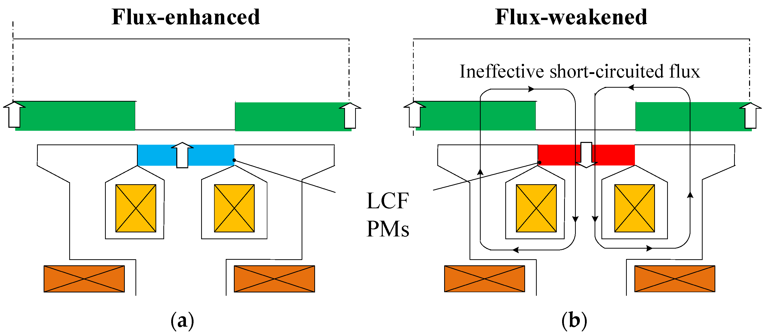
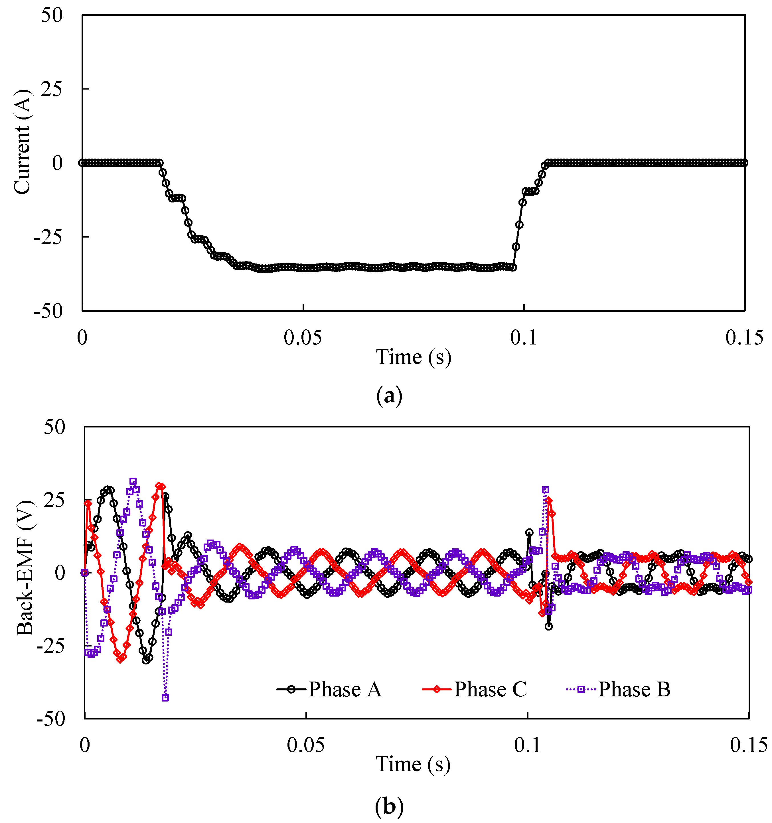
2.3. Field Regulatable Principle

The field regulatable principle of the proposed DCP-VMM is portrayed in Figure 5. The iron poles on both stator and rotor sides provide an effective circulation path for either the stator- or rotor-magnet field. The magnetization level and polarity of LCF PMs can be changed via a current pulse energized in the magnetizing coils. Hence, the effective flux linked with the armature windings can be strengthened or weakened when the magnetized directions of LCF magnets are identical or opposite to those of NdFeB PMs. The corresponding field distributions are shown in Figure 6a,b, which well reflects the excellent flux adjustable capability. Furthermore, the variation of the self-inductance of the DC magnetizing coils is shown in Figure 7. The inductance not only depends on the magnetic circuit for armature flux-linkage, but the magnetic saturation at the different magnetization states. Thus, when the LCF PMs are magnetized in different directions, the inductance values will change. The self-inductance of magnetizing coil can be calculated by injecting a dc field current excitation as:
L a a = Ψ m Ψ m 0 I m
where Ψm is the flux-linkage of the magnetizing coil due to magnets and field current, Ψm0 is the flux-linkage of the magnetizing coil due to magnets only. Obviously, some negligible fluctuations in the inductance profile can be observed, which implies that the circulating permeance for transient magnetizing or demagnetizing fields uniformly varies with the rotor position.
That is to say, the flux control is less dependent on the rotor position, thus the validity of the DC magnetizing coils for online magnetization control is confirmed. Furthermore, the transient response of open-circuit back-EMF to a demagnetizing current pulse of −35 A is plotted in Figure 8. It demonstrates that the flux-adjustability can be easily achieved by a current pulse.

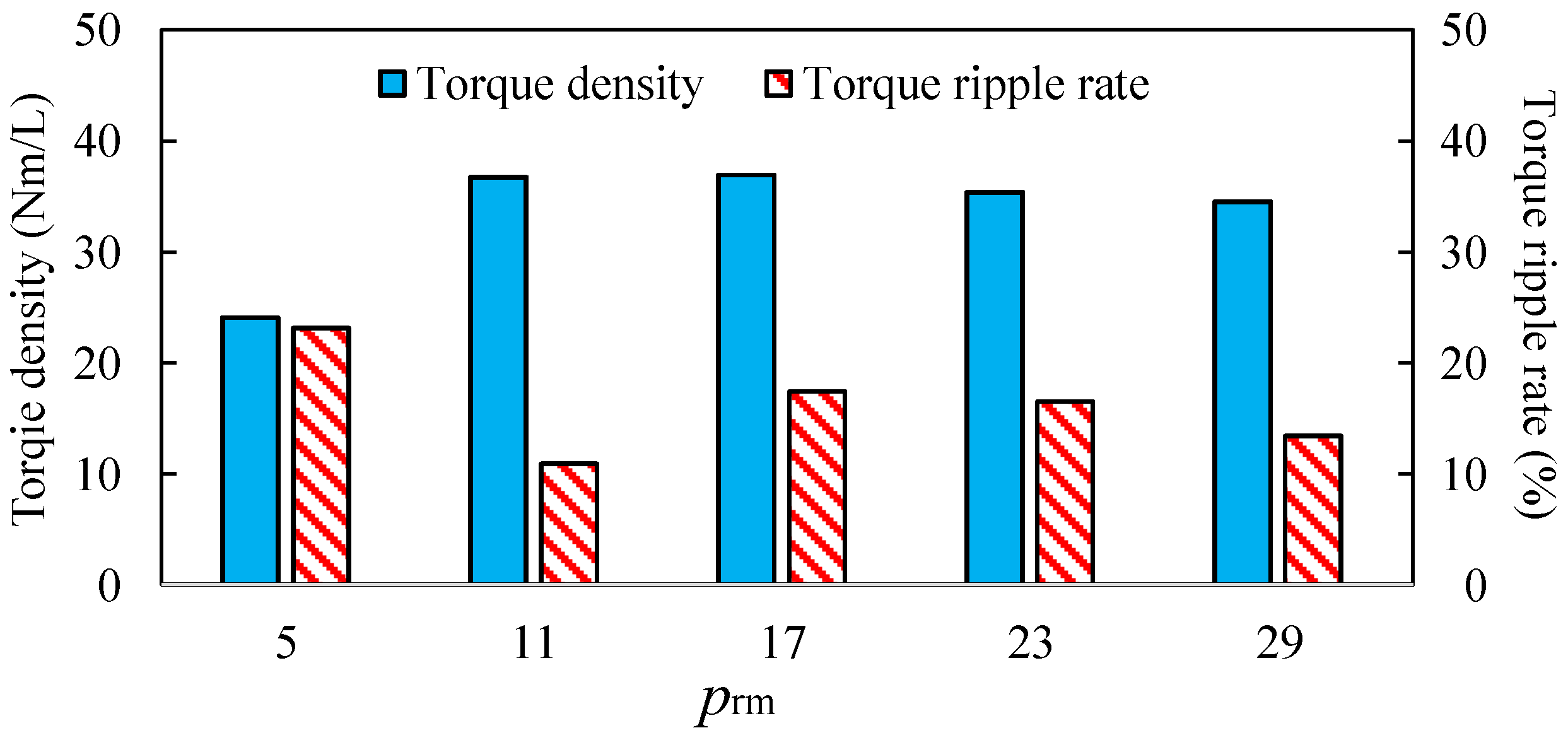
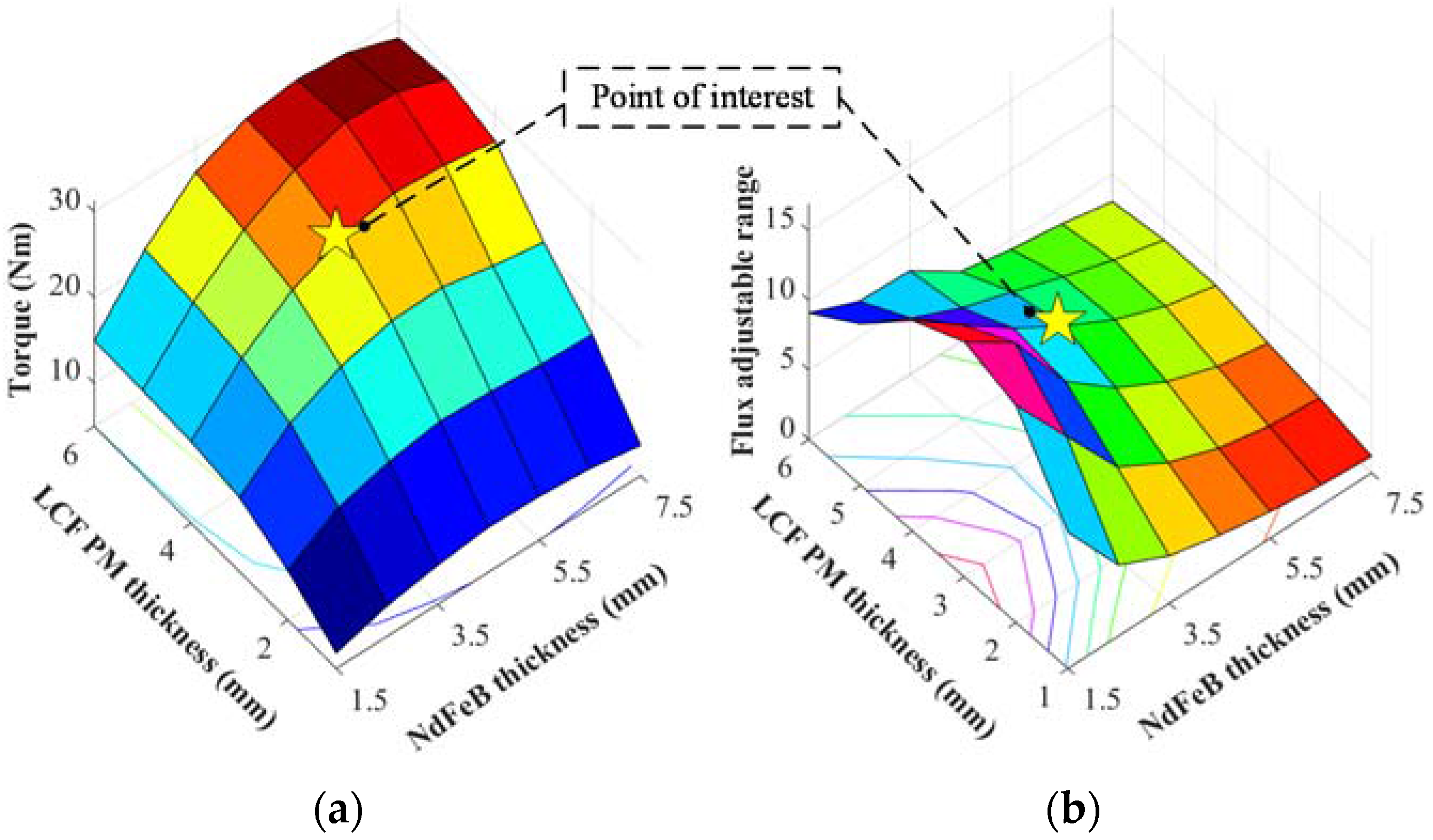
3. Design Considerations

Since various combinations of the stator and rotor pole numbers are available for the proposed DCP-VMM, the preliminary design work involves selecting the most feasible psm/prm for improving torque quality, etc. This paper focuses on the VM groups with pw1 = 1, which appear to show higher torque densities [11,12]. As the armature slot number is fixed at 6 in this case, the possible prm is 5, 11, 17, 23, and 29, etc. The machine configurations having alternate stator/rotor combinations (prm = 5, 17, 23, and 29) are shown in Figure 9. Commonly, each stator pole is split into two iron poles, and LCF PMs are alternatively embedded between the adjacent iron poles. The torque density and torque ripple rate (defined as the peak-to-peak torque ripple to the average torque) at the flux-enhanced state are calculated as shown in Figure 10. It can be observed that the proposed machine having prm = 11 exhibits favorable torque performance, which will be chosen for further analysis.
The influences of the radial thicknesses of NdFeB and LCF PMs on torque capability and flux adjustable range, defined as the ratio of the fundamental back-EMF magnitudes at flux-enhanced and weakened states, are calculated as shown in Figure 11. The optimal NdFeB and LCF thicknesses can be obtained, i.e., 4.5 mm and 4 mm, which satisfactorily realizes the tradeoff between torque enhancement and speed range extension.

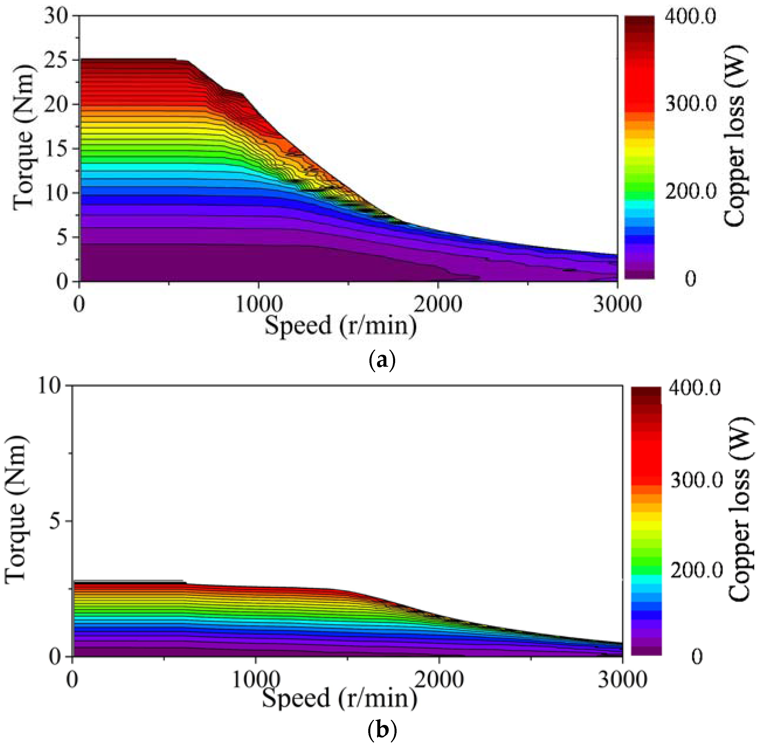
4. Electromagnetic Performance Analysis

The electromagnetic performance of the proposed DCP-VMM is analyzed by a coupled solution [26]. JMAG 14.0 software package is utilized for FEM analysis. The “Shared Memory Multiprocessing (SMP)” with eight degrees of parallelism is employed in the solver. For the nonlinear calculation, the “Newton-Raphson” method with maximum nonlinear iterations of 50 and convergence tolerance of 0.001 is adopted, which has been proven to work very well to deal with the nonlinearity of B-H curve of magnetic material in large number of calculation examples. For the mesh setting, the option of “slide motion mesh” is adopted to improve the accuracy of calculation by adjusting the element size in the gap at each step. The optimized design parameters are tabulated in Table 1. Figure 12 shows the open-circuit back-EMF waveforms and harmonic spectra at different magnetization states of LCF magnets (300 r/min). It demonstrates that the back-EMF can be flexibly adjusted by changing the magnetization levels and polarities of LCF PMs, which benefits the wide-speed range applications. Besides, it can be observed that the flux-weakened effect appears to be more obvious than the flux-enhanced one, which is mainly attributed to the significant magnetic saturation at the flux-enhanced state, and hence the magnetic reluctance for armature field circulating is increased. The highest total harmonic distortion (THD) occurs at the flux-weakened state, which can be reflected in Figure 12b.
The torque characteristics under different magnetization states are evaluated as shown in Figure 13. The highest torque ripple of 46.3% can be found at the flux-weakened state, while the torque ripples only account for 10.9% and 13.1% of the average torque for the other two states. The high THD of back-EMF and high ratio of peak-to-peak cogging to the average torque, as well as reluctance torque ripple at the flux-weakened state are responsible for the torque ripple. It should be noted that the current angle advance control can be adopted when the machine operates at the flux-weakened state owing to the positive saliency ratio >“1”.
The iron and copper loss distributions within a whole operating envelop at different magnetization states are shown in Figure 14 and Figure 15, respectively. It can be observed that the iron loss, particularly in the high-speed region, can be significantly reduced via the flux-weakened control, which appears to be a dominant loss component in high-speed operation. This is mainly attributed to the field weakening effect due to the massively short-circuiting PM fluxes. This merit results in the flux-weakening performance improvement, as can be well reflected in Figure 16c. Figure 16 shows the efficiency maps of the proposed DCP-VMM. It should be noted that due to the relatively low power factor (0.63) at rated condition, the inverter capacity is inevitably increased with high voltage rating. In this case, the maximum applied voltage (124.7 V) and control strategy (maximum-torque-per-ampere) are employed in the calculation of the torque-speed curves. It can be observed that the optimal operating regions varies with different magnetization states, viz., the high efficiency improvement within a wide range of operating envelop can be obtained by combining the magnetization states at speed and loads.

5. Conclusions

In this paper, a novel DCP-VMM having alternatively placed NdFeB and LCF magnet poles on the rotating and stationary sides, respectively was designed. The underlying operating principle of the proposed machine is theoretically elaborated from a perspective of the geometric decomposition into a rotor- and stator-PM Vernier machines respectively. Consequently, the machine can perform dual magnetic-gearing effects. The stator/rotor pole number combinations, together with magnet parameters are optimized. It can be concluded that the machine configuration with prm/psm = 11/12 can offer the desired torque density with the lowest torque ripple. The analysis results demonstrate that the proposed DCP-VMM can readily combine the distinct synergies of Vernier machine with dual PM excitations and memory machine. The merits of low-speed high-torque and high efficient online flux-regulation can be simultaneously achieved, which are highly favorable for automotive applications. Future works will focus on the detailed sizing procedure, loss calculation, thermal modelling, control strategy and transient performance of this machine. A prototype with optimal design parameters will be manufactured, and the test results including static as well as dynamic performance will be reported in future papers.

Acknowledgments

This work was jointly supported by National Natural Science Foundation of China (51377020), Specialized Research Fund for the Doctoral Program of Higher Education of China (20130092130005), and the Scientific Research Foundation of Graduate School of Southeast University. The first author, Hui Yang, would like to thank the China Scholarship Council to financially support the one-year joint studentship at The University of Sheffield.

Author Contributions

All authors have contributed to this work. Hui Yang conceived of the idea of the research, implemented the machine design as well as performance analyses. Heyun Lin and Zi-Qiang Zhu provided technical guidance for research work and paper writing. This manuscript was improved and revised by Shuhua Fang and Yunkai Huang.

Conflicts of Interest

The authors declare no conflict of interest.

References

  1. Rahman, K.M.; Patel, N.R.; Ward, T.G.; Nagashima, J.M.; Caricchi, F.; Crescimbini, F. Application of direct-drive wheel motor for fuel cell electric and hybrid electric vehicle propulsion system. IEEE Trans. Ind. Appl. 2006, 42, 1185–1192. [Google Scholar] [CrossRef]
  2. Zhu, Z.Q.; Howe, D. Electrical machines and drives for electric, hybrid and fuel cell vehicles. IEEE Proc. 2007, 95, 746–765. [Google Scholar] [CrossRef]
  3. Chau, K.T.; Chan, C.C.; Liu, C. Overview of permanent-magnet brushless drives for electric and hybrid electric vehicles. IEEE Trans. Ind. Electron. 2008, 55, 2246–2257. [Google Scholar] [CrossRef] [Green Version]
  4. Jian, L.; Shi, Y.; Wei, J.; Zheng, Y. Design and analysis of a direct-drive wind power generator with ultra-high torque density. J. Appl. Phys. 2015, 117. [Google Scholar] [CrossRef]
  5. Liu, C.; Chau, K.T.; Zhang, Z. Novel design of double-stator single-rotor magnetic-geared machines. IEEE Trans. Magn. 2012, 48, 4180–4183. [Google Scholar] [CrossRef] [Green Version]
  6. Zheng, P.; Song, Z.; Bai, J.; Tong, C.; Yu, B. Research on an axial magnetic-field-modulated brushless double rotor machine. Energies 2013, 6, 4799–4829. [Google Scholar] [CrossRef]
  7. Zheng, P.; Zhao, Q.; Bai, J.; Yu, B.; Song, Z.; Shang, J. Analysis and design of a transverse-flux dual rotor machine for power-split hybrid electric vehicle applications. Energies 2013, 6, 4548–4568. [Google Scholar] [CrossRef]
  8. Jian, L.; Chau, K.T.; Jiang, J.Z. A magnetic-geared outer-rotor permanent-magnet brushless machine for wind power generation. IEEE Trans. Ind. Appl. 2009, 3, 954–962. [Google Scholar] [CrossRef]
  9. Wang, L.; Shen, J.X.; Luk, P.C.K.; Fei, W.-Z.; Wang, C.; Hao, H. Development of a magnetic-geared permanent-magnet brushless motor. IEEE Trans. Magn. 2009, 45, 4578–4581. [Google Scholar] [CrossRef] [Green Version]
  10. Liu, C.; Chau, K.T.; Qiu, C. Design and analysis of a new magnetic-geared memory machine. IEEE Trans. Appl. Supercond. 2014, 24, 1–5. [Google Scholar]
  11. Kim, B.; Lipo, T.A. Operation and design principles of a PM vernier motor. IEEE Trans. Ind. Appl. 2014, 50, 3656–3663. [Google Scholar] [CrossRef]
  12. Li, D.; Qu, R.; Lipo, T.A. High-power-factor vernier permanent-magnet machines. IEEE Trans. Ind. Appl. 2014, 50, 3664–3674. [Google Scholar] [CrossRef]
  13. Li, J.; Chau, K.T.; Jiang, J.Z.; Liu, C.; Li, W. A new efficient permanent-magnet vernier machine for wind power generation. IEEE Trans. Magn. 2010, 46, 1475–1478. [Google Scholar] [CrossRef] [Green Version]
  14. Spooner, E.; Haydock, L. Vernier hybrid machines. IEE Proc. Elec. Power Appl. 2003, 6, 655–662. [Google Scholar] [CrossRef]
  15. Niu, S.; Ho, S.L.; Fu, W.N. A novel stator and rotor dual PM vernier motor with space vector pulse width modulation. IEEE Trans. Magn. 2014, 50, 805–808. [Google Scholar] [CrossRef]
  16. Jian, L.; Xu, G.; Mi, C.; Chau, K.T.; Chan, C.C. Analytical method for magnetic field calculation in a low-speed permanent-magnet harmonic machine. IEEE Trans. Energy Convers. 2011, 26, 862–870. [Google Scholar] [CrossRef] [Green Version]
  17. Liu, C.; Zhong, J.; Chau, K.T. A novel flux-controllable vernier permanent-magnet machine. IEEE Transactions Magn. 2011, 47, 4238–4241. [Google Scholar] [CrossRef] [Green Version]
  18. Ostovic, V. Memory motors. IEEE Ind. Appl. Mag. 2003, 9, 52–61. [Google Scholar] [CrossRef]
  19. Liu, H.; Lin, H.; Zhu, Z.Q.; Huang, M.; Jin, P. Permanent magnet remagnetization physics of a variable flux memory motor. IEEE Trans. Magn. 2010, 46, 1679–1682. [Google Scholar] [CrossRef]
  20. Lee, J.H.; Hong, J.P. Permanent magnet demagnetization characteristic analysis of a variable flux memory motor using coupled Preisach modeling and FEM. IEEE Trans. Magn. 2008, 44, 1550–1553. [Google Scholar] [CrossRef]
  21. Yu, C.; Chau, K.T. Design, analysis, and control of DC-excited memory motors. IEEE Trans. Energy Convers. 2011, 26, 479–489. [Google Scholar] [CrossRef] [Green Version]
  22. Yang, H.; Lin, H.; Dong, J.; Yan, J.; Huang, Y.; Fang, S. Analysis of a novel switched-flux memory motor employing a time-divisional magnetization strategy. IEEE Trans. Magn. 2014, 50, 849–852. [Google Scholar] [CrossRef]
  23. Yang, H.; Zhu, Z.Q.; Lin, H.; Fang, S.; Huang, Y. Comparative study of novel variable-flux memory motor having stator permanent magnet topologies. IEEE Trans. Magn. 2015, 51, 8114104. [Google Scholar] [CrossRef]
  24. Yang, H.; Zhu, Z.Q.; Lin, H.; Fang, S.; Huang, Y. Novel alternative switched flux memory machines having hybrid magnet topologies. In Proceedings of the International Conference on Ecological Vehicle and Renewable Energies (EVER), Monaco, 31 March–2 April 2015; pp. 1–9.
  25. Yang, H.; Lin, H.; Zhu, Z.Q.; Fang, S.; Huang, Y. Novel flux-regulatable dual-magnet vernier memory machines for electric vehicle propulsion, IEEE Trans. Appl. Supercond. 2014, 24, 0601205. [Google Scholar]
  26. Yang, H.; Lin, H.; Fang, S.; Zhu, Z.Q.; Huang, Y. Flux-regulatable characteristics analysis of a novel switched-flux surface-mounted PM memory machine. IEEE Trans. Magn. 2014, 50, 8103904. [Google Scholar] [CrossRef]
Figure 1. Proposed DCP-VMM. (a) Exploded view; (b) Cross-section.
Energies 09 00134 g001
Figure 2. Machine decomposition schematics. (a) Rotor-PM; (b) Stator-PM.
Energies 09 00134 g002
Figure 3. Field distributions excited by (a) hybrid PMs; (b) rotor-PM; (c) stator-PM; (d) armature reaction.
Energies 09 00134 g003
Figure 4. Air-gap flux density waveforms and harmonic spectra contributed by (a) PMs; (b) armature reaction; (c) Harmonic spectra.
Energies 09 00134 g004
Figure 5. Field regulatable principle. (a) Flux-enhanced; (b) Flux-weakened.
Energies 09 00134 g005
Figure 6. Field distributions of DCP-VMM subjected to different magnetization states. (a) Flux-enhanced; (b) Flux-weakened.
Energies 09 00134 g006
Figure 7. Variations of the self-inductance of the magnetizing coils in DCP-VMM.
Energies 09 00134 g007
Figure 8. Simulated transient response of open-circuit back-EMF of DCP-VMM to a demagnetizing current pulse. (a) Current pulse; (b) Back-EMF waveforms.
Energies 09 00134 g008
Figure 9. DCP-VMM structures having alternate stator/rotor pole number combinations. (a) 3-slot/10-pole; (b) 9-slot/34-pole; (c) 12-slot/46-pole; (d) 15-slot/58-pole.
Energies 09 00134 g009
Figure 10. Torque quality versus various rotor pole pair numbers.
Energies 09 00134 g010
Figure 11. PM parametric optimizations on (a) torque and (b) flux adjustability.
Energies 09 00134 g011
Figure 12. Back-EMF characteristics subjected to various magnetization states, 300 r/min. (a) Waveforms; (b) Harmonic spectra.
Energies 09 00134 g012
Figure 13. Torque characteristics. (a) Cogging torque; (b) Torque against current angle; (c) Torque against current characteristics; (d) Steady-state torque, rated RMS current = 10 A.
Energies 09 00134 g013
Figure 14. Iron loss maps. (a) Flux-enhanced; (b) Flux-weakened, DC link voltage = 216 V, rated RMS current = 10 A.
Energies 09 00134 g014
Figure 15. Copper loss maps. (a) Flux-enhanced; (b) Flux-weakened, DC link voltage = 216 V, rated RMS current = 10 A.
Energies 09 00134 g015
Figure 16. Efficiency maps. (a) Flux-enhanced; (b) Zero magnetized; (c) Flux-weakened, DC link voltage = 216 V, rated RMS current = 10 A.
Energies 09 00134 g016
Table 1. Key Design Parameters of Proposed DCP-VMM.
ItemParameter
Slot/pole number6/22
No. of stator teeth2 × 6
Rated speed (r/min)300
Stack length (mm)50
Outer radius of rotor (mm)70
Air-gap length (mm)0.6
NdFeB/LCF PM thick. (mm)4.5/4
Split ratio0.7
Stator/rotor pole arc (degree)20/11
Rated current (A)10
Power factor0.63
NdFeB gradeN35

