Article

Combustion and Emission Characteristics According to the Fuel Injection Ratio of an Ultra-Lean LPG Direct Injection Engine

Department of Engine Research, Environmental and Energy Systems Research Division, Korea Institute of Machinery and Materials, Daejeon 34103, Korea
*
Author to whom correspondence should be addressed.
Energies 2016, 9(11), 920; https://doi.org/10.3390/en9110920
Submission received: 27 June 2016 / Revised: 5 October 2016 / Accepted: 1 November 2016 / Published: 7 November 2016

Abstract

:
The effect of the fuel injection ratio on the combustion and emission characteristics of stratified lean mixture combustion was investigated for a spray-guided liquefied petroleum gas (LPG) direct injection engine. Inter-injection spark-ignition combustion—a specially designed combustion strategy for LPG fuel derived from a two-staged injection—was employed to maximize the improvement in thermal efficiency when combustion stability is secured. When changing the fuel injection ratio, the optimum spark advance and fuel injection timings were experimentally determined to maximize the thermal efficiency based on sweeping timings. The optimum fuel injection ratio with the highest thermal efficiency (42.76%) and stable operation was 60%/40%, with the optimization of the spark advance and fuel injection timing, because of the locally rich mixture region in the recirculation zone. NOx emissions were at their highest level with a fuel injection ratio of 60%/40% because of the high combustion temperature, and the levels of total hydrocarbon and CO emissions with 50%/50% and 60%/40% fuel injection ratios were similar, whereas emissions at 70%/30% were significantly higher because of fuel wetting and the formation of over-lean mixture.

1. Introduction

Given the recent rise in oil consumption combined with global concerns regarding greenhouse gas accumulation and fossil fuel depletion, researchers are attempting to develop technologies to enable low carbon dioxide (CO2) emissions and low fuel consumption [1,2]. Typically, an engine with a spark ignition system uses a stoichiometric air-fuel ratio by controlling the throttle opening and fuel injection duration of the injector for air and fuel, respectively, while utilizing a three-way catalyst to reduce harmful exhaust emissions [3]. However, as controlling the intake air amount increases the fuel consumption because of the occurrence of pumping loss, the high specific fuel consumption must be reduced to the level of the compression-ignition diesel engine. The use of lean combustion can be an alternative to solve the problem of high fuel consumption and exhaust gas emissions. Since liquefied petroleum gas (LPG)—a low-carbon gas fuel—has the potential for reducing emissions and also improving fuel economy, ultra-lean LPG direct injection engine technology has attracted attention. Boretti et al. [4] presented a computer model for analyzing direct injection engines with spark ignition and reported that specific fuel consumption might be reduced through LPG-stratified lean combustion. Kim et al. [5] investigated total hydrocarbon (THC) and nanoparticle emissions from an LPG direct injection engine during cold start. In this study, we report the comparison analysis on the performance and emission characteristics of gasoline and LPG. An optimized fuel injection strategy for LPG is proposed and the effect of excess air ratio is assessed in the spray-guided LPG direct-injection combustion system [6,7].
A method to implement lean combustion is categorized by the utilization of a homogeneous or stratified mixture. In a homogeneous-mixture combustion system, for a spark-ignited lean fuel air mixture uniformly mixed and supplied throughout the combustion chamber, off-lean limits of the fuel make it impossible to maintain a stable combustion with a typical ignition system. Techniques for improving the ignition quality of fuel have been studied to create a high-energy utilization method, such as the plasma jet, and multi-charge ignition systems have been developed to provide strong initial ignition energy and high current [8,9]. In addition, Toyota Motor Corporation and Mitsubishi Motors have designed the intake port shape to improve the internal flow of the combustion chamber by using devices such as a swirl control valve to achieve lean combustion. However, the largest amount of excess air yielding stable combustion is at level 1.5, which is still not competitive with level 4 of diesel engines [10,11,12,13].
Stratified mixture combustion of a lean air-fuel mixture employs stratification to form a rich mixture near a spark plug. As stratification is easy to implement by adjusting the timing of fuel directly injected into the combustion chamber, it is common to use a high-pressure fuel supply direct injection system to overcome high in-cylinder pressure, thus requiring an injection device. Stratified mixture combustion systems are classified as wall- or spray-guided. Wall-guided systems were first seen implemented by Mitsubishi in 1995 [11]. However, drawbacks of such systems, including unstable combustion, have led to the use of ultra-lean direct injection engines, employing spray-guided systems, in recent years. In a lean burn engine with a spray-guided combustion system, a fuel injector is positioned at the center of the combustion chamber as in a diesel engine; the discharge electrode of the spark plug lies in the recirculation zone of the spray. As the nozzle tip of the injector is located very close to the spark plug, the air-fuel mixture is determined not by the intake airflow and the piston position but by the shape of the fuel spray, such as penetration and angle, formed to fill a thick air-fuel mixture around the spark plug. However, as the formation time of the stratified air-fuel mixture is very short, the response speed of the injector to adjust the air-fuel ratio distribution of the mixture is important for atomization of the fuel spray [14,15]. In general, the lean combustion of a premixed lean mixture in a spark ignition engine causes torque variation due to unstable operation. This instability problem can be solved through mixture stratification around the spark plug to form a sufficiently rich mixture that can be stably ignited. However, since a stratified-charge lean-combustion discharges relatively high levels of nitrogen oxides (NOx) and particulate matters (PM) because of combustion of the locally rich mixture, the use of LPG can be proposed as an alternative for reducing PM because of its low carbon characteristics and high vapor pressure in spray-guided combustion systems [16,17].
Peterson et al. [18] provided quantitative measurements of equivalence ratio and flow velocity within the tumble plane of a spray-guided direct-injection spark-ignition optical engine, and showed the spatial and temporal evolutions of fuel distribution and flow velocity on flame kernel development. In [16,17], we evaluated the effect of the split-injection strategy and analyzed the lean combustion characteristics of a spray-guided direct-injection combustion system. Piock et al. [19] employed a multicharge-ignition system developed to extend the misfire-free operating range in a stratified-gasoline direct-injection engine, and the system provided a high spark energy that helped develop a strong flame kernel, which resulted in a stable lean burn operation.
LPG is an attractive alternative fuel with a high amount of heat generated per unit weight compared to conventional fuel, as well as a high octane number and reduced emissions of harmful exhaust gases. In addition, several studies have developed an LPG engine technology utilizing a wall-guided system to directly inject fuel into the combustion chamber. Further, the development of LPG direct injection vehicles for commercialization began in 2011, with hopes of a mass production system by the end of 2016. This technique is capable of satisfying both EURO-VI (European Union) and SULEV (North America) regulations for emissions. Myung et al. [20,21] compared toxic emissions of gasoline and LPG from direct-injection light-duty vehicles and evaluated the effect of engine control strategies on particulate emissions. In addition, studies on lean-burn LPG direct-injection engines with spray-guided combustion systems have been conducted as a part of future engine technology development [6,7,22].
However, the engine performance is greatly affected by the spray shape and spark plug performance. Particularly, owing to the low saturated vapor pressure in LPG fuel, excellent evaporation characteristics are possible only through the optimization of fuel injection and ignition strategies to yield a stable, lean burn [6,23,24].
From experimental results of previous studies [25], the lean combustion limit is equal to the excess air ratio of 4.93 at operating conditions of 1500 rpm and brake mean effective pressure (BMEP) 0.15 MPa. In addition, this limit improves specific fuel consumption by 27.5% compared with the reference to the stoichiometric air-fuel ratio. As the maximum combustion temperature is reduced because of the use of ultra-lean combustion, the emissions of NOx and carbon monoxide (CO) are substantially reduced. However, the optimal fuel injection, spark ignition timing, and ratio of injected fuel amount can differ according to the operating point. As the formation of an appropriate stratified mixture is difficult with a single injection at a certain operating condition, multiple injection strategies were employed in the previous studies [7,16,17,22,25]. In the present study, a two-staged injection strategy is applied and optimized. In addition, this study aims to observe the combustion and emission characteristics with different operating conditions, and the effect of changing fuel injection ratio was evaluated in a spray-guided LPG direct injection engine.

2. Experimental Procedures

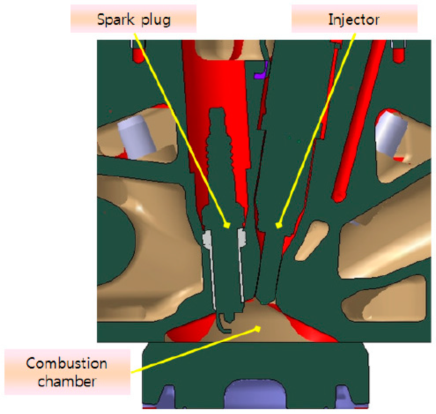
2.1. Experimental Setup

In the present study, to apply ultra-lean combustion and supply LPG fuel by using the direct injection technology in a conventional mass-production port-fuel-injection engine, the engine and its auxiliary machinery was modified, as shown in Figure 1. The experimental engine setup in this study is the same as that used in previous researches [6,7,22]. The head of the 2.0 L gasoline engine with a port fuel injection system was redesigned for the development of an ultra-slim LPG direct-injection engine, and therefore the position of the spark plug and fuel injector, were altered to conform to the requirements of the spray-guided combustion system.
Table 1 summarizes the specifications of the original gasoline engine. A piezo-type fuel injection system with an outwardly opening nozzle was applied to allow up to four injections in one cycle. The characteristics of the outwardly opening nozzle, such as the mixture formation and fuel vaporization, were reported in previous studies [22,26,27].
LPG fuel was supplied from the compressed fuel tank to the high-pressure fuel supply system at a pressure of 0.5 MPa by using a low-pressure fuel pump inside the LPG storage tank, and subsequently the fuel was fed through the high-pressure pump to the common rail. As a matter of fact, the residual fuel that has not been injected increases its temperature during the recirculation and creates issues for the high-pressure pump. This is because of the considerable change in the saturated vapor pressure of the LPG fuel with temperature. To mitigate this, the temperature of fuel supply to the high-pressure pump was controlled using a heat exchanger installed in the middle of the fuel supply channel. The plunger high-pressure fuel pump utilized three pistons to pressurize the fuel up to 25 MPa. The fuel injection pressure was maintained using a pressure control valve equipped in the common rail at a constant pressure of 20 MPa. A piezo-injector was driven by an engine control unit (ECU) that controlled the fuel injection quantity supplied to the combustion chamber, injection timing, and spark ignition timing. To measure the excess air ratio, a wide-band oxygen sensor (LSU 4.2/LA4, ETAS Co.) (ETAS, Stuttgart, Germany) was installed in the respective cylinders and exhaust manifold, and the state of the burned mixture was determined in real time.
To check the combustion characteristics in the chamber, a pressure sensor was fitted in the cylinder. The measured signal from the pressure sensor was acquired using a combustion analyzer (Osiris, D2T Co.) (D2T, Trappes, France) and used for calculating the indicated mean effective pressure (IMEP) and coefficient of variation (COV) for an ensemble average of 200 cycles in real time. The COV value indicates the combustion stability and is compared to that of a stable operation condition (below 5%) [8,9]. Exhaust gases collected from the exhaust pipe were analyzed using an exhaust gas analyzer (AMA i60, AVL Co.) (AVL, Graz, Austria).

2.2. Experimental Methods

In the present study, we conducted an experiment at 1500 and 1600 rpm rotation speeds with BMEPs of 0.15 and 0.24 MPa, respectively. The optimum injection and ignition timing are defined based on the highest thermal efficiency. The excess air ratio was determined at lean combustion limits with a fixed wide-open throttle for each operation point. To effectively stabilize the lean combustion, a two-staged injection strategy was employed. Fuel injection ratios of the multistage injection were applied at 50%/50%, 60%/40%, and 70%/30%. The temperature of the cooling water was set by using the temperature control system to maintain the engine at 80 ± 2 °C. Table 2 summarizes the controlled combustion parameters for each operating condition.

3. Results

One of the main objectives of this study is to evaluate the effects on engine performance and emission characteristics due to different LPG-stratified lean combustions close to the lean-burn stability limit. In fact, the effects of different excess air ratios on performance and emission were reported in previous studies [6,7]. To ensure the combustion stability of LPG lean burn operation, a modified multiple-injection strategy was adopted, designated as the inter-injection spark ignition (ISI), as introduced in a previous study [6]. ISI features a spark discharge between the first and second fuel injections. This spark discharge occurs immediately after the first fuel injection and before the start of the second fuel injection so that the locally rich mixture can be ignited before the first fuel dispersion. Thus, the second-injected fuel is ignited by the flame from the first injection. The optimum values of parameters for ISI, such as the amount of the first and second fuel injections, spark advance (SA), and each fuel injection timing, should be determined for each engine operating point [7]. The optimum combustion with the emission results was obtained by changing the SA and fuel injection timing, while changing the fuel injection ratio. The lean combustion improved the specific fuel consumption and decreased THC and NOx emissions, while the stable combustion was secured using optimized fuel injection parameters of the ISI strategy.

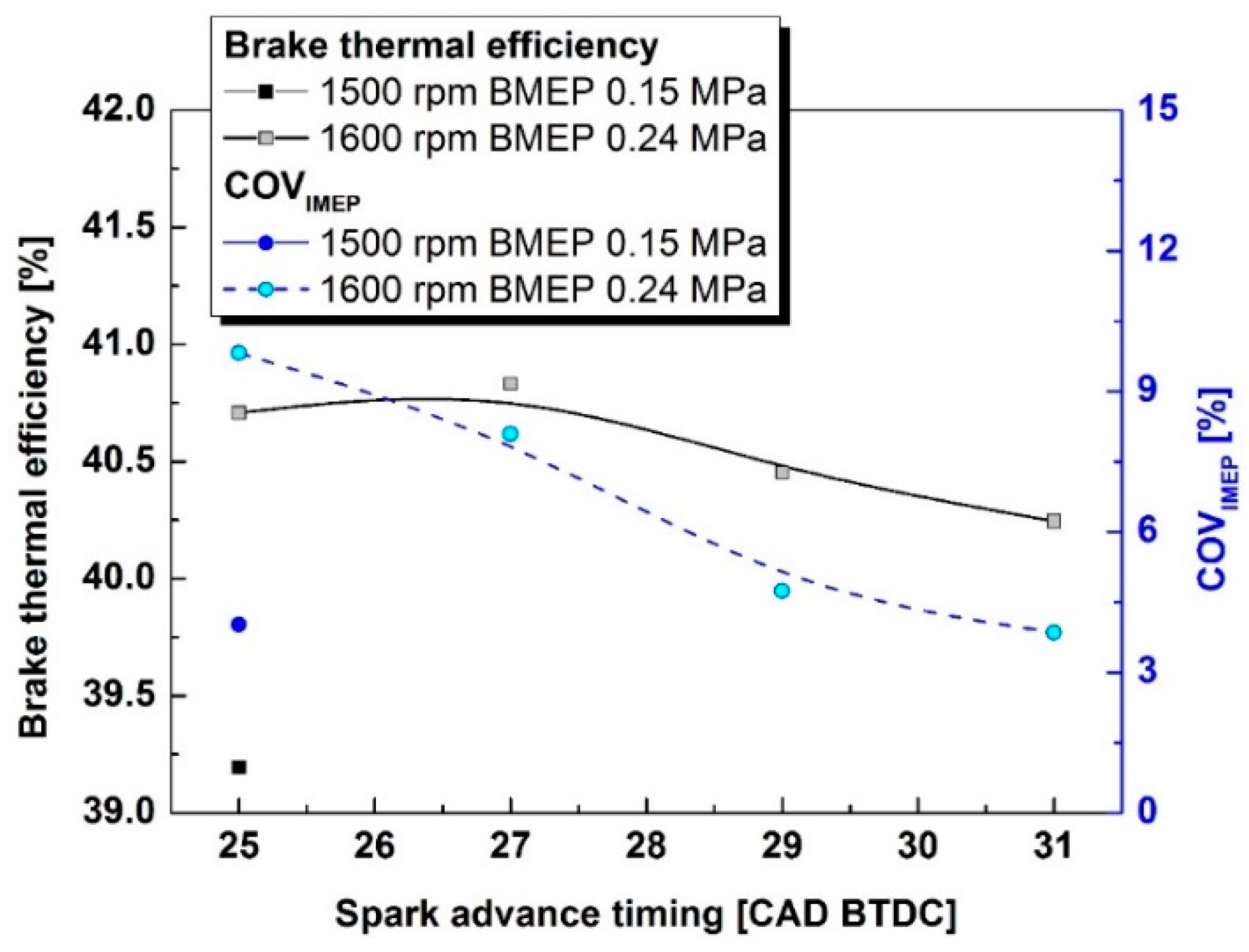
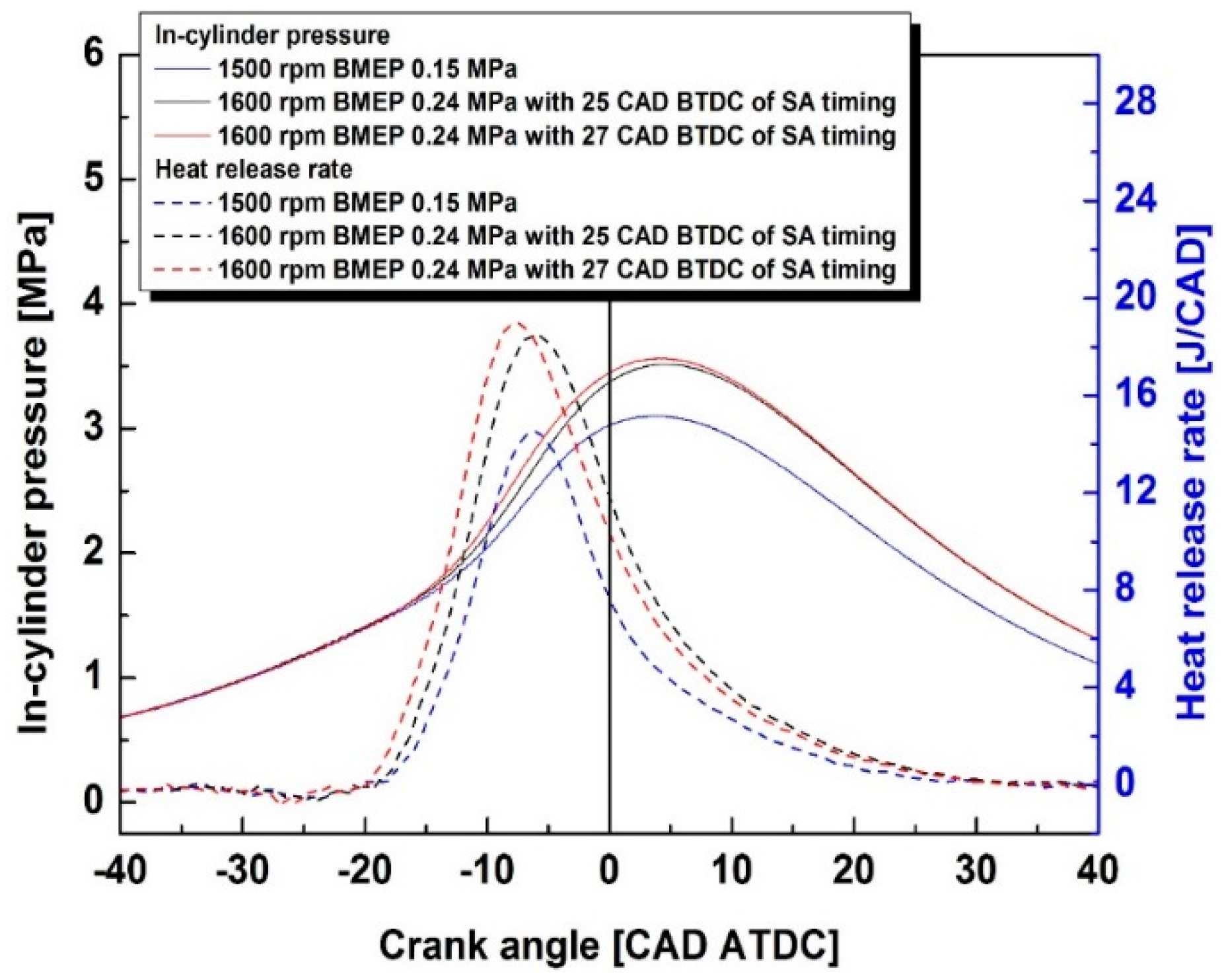
3.1. Effect of SA on Efficiency and Combustion Stability

Figure 2 shows the results of brake thermal efficiency and combustion stability for the stratified lean combustions at 1500 and 1600 rpm with BMEPs of 0.15 and 0.24 MPa, respectively. The fuel injection ratio of each injection was set at 50%/50%. Based on the previous study, after sweeping the SA and fuel injection timing, the SA timing for a maximum brake torque (MBT) was determined to be 25 crank angle degree (CAD) before top dead center (BTDC). In addition, the first and second fuel injection timings were 27 and 19 CAD BTDC respectively, at an operation point of 1500 rpm and 0.15 MPa BMEP. The thermal efficiency and combustion stability with various SA timings at 1600 rpm and BMEP 0.24 MPa were compared to those with MBT spark timing at 1500 rpm and BMEP 0.15 MPa. To isolate the effect of SA, its location relative to the fuel injection is maintained constant. Accordingly, the start of the second injection is always placed 7 CAD after the start of the first injection. The first injection always occurs 2 CAD before the spark ignition. The duration for both fuel injections is approximately 380 μs and varies with the change in brake thermal efficiency at a certain load operating condition.
The levels of thermal efficiency are higher than at 1500 rpm, BMEP 0.15 MPa because the mechanical efficiency increases with the load, while the engine speeds do not differ considerably. Therefore, the mechanical losses remain almost constant, whereas the indicated MEP increases [9]. Further, the highest thermal efficiency was confirmed at an SA timing of 27 CAD BTDC, and COVIMEP was determined to be higher than the limit required for stable operation. COVIMEP values decrease as the fuel injection and SA timing are advanced. As reported in a previous study, the ignition of the stratified mixture is affected by the spray pattern [22], which in turn can be affected by ambient pressure and piston position. The piston is closer to the fire deck at 27 and 29 CAD BTDC of the first fuel injection timing (25 and 27 CAD BTDC of the SA timing) than at other SA timing conditions. Consequently, it is believed that the increase in the local rich-mixture region near the spark plug due to the relatively late injection timing deteriorates the combustion stability, whereas the COVIMEP values at the SA timing of 29 and 31 CAD BTDC satisfy the standard for stable combustion: 5%.
The decrease in brake thermal efficiency at a more advanced SA timing than 27 CAD BTDC can be understood from the in-cylinder pressure traces and apparent heat release rate for each operation point, as shown in Figure 3. The peak heat release rates are measured at approximately −10 CAD after top dead center (ATDC). As the SA timing is advanced, the position of the peak heat-release rate advances, increasing the portion of heat release in the compression stroke and decreasing it in the expansion stroke. Although the combustion stability is secured with the first fuel injection and subsequent spark discharge, the heat release does not efficiently translate into combustion power when the piston is still moving upward toward the TDC.

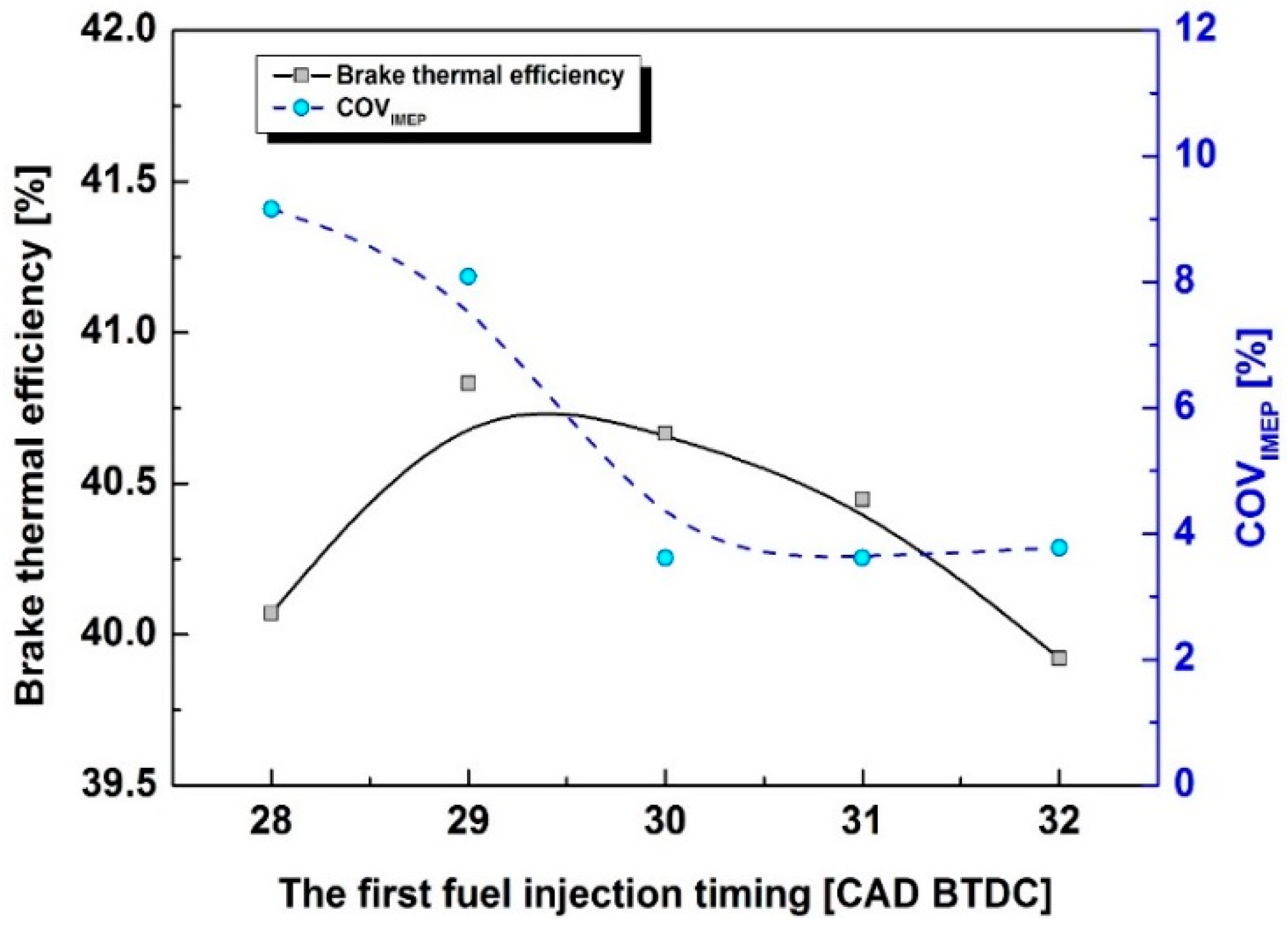
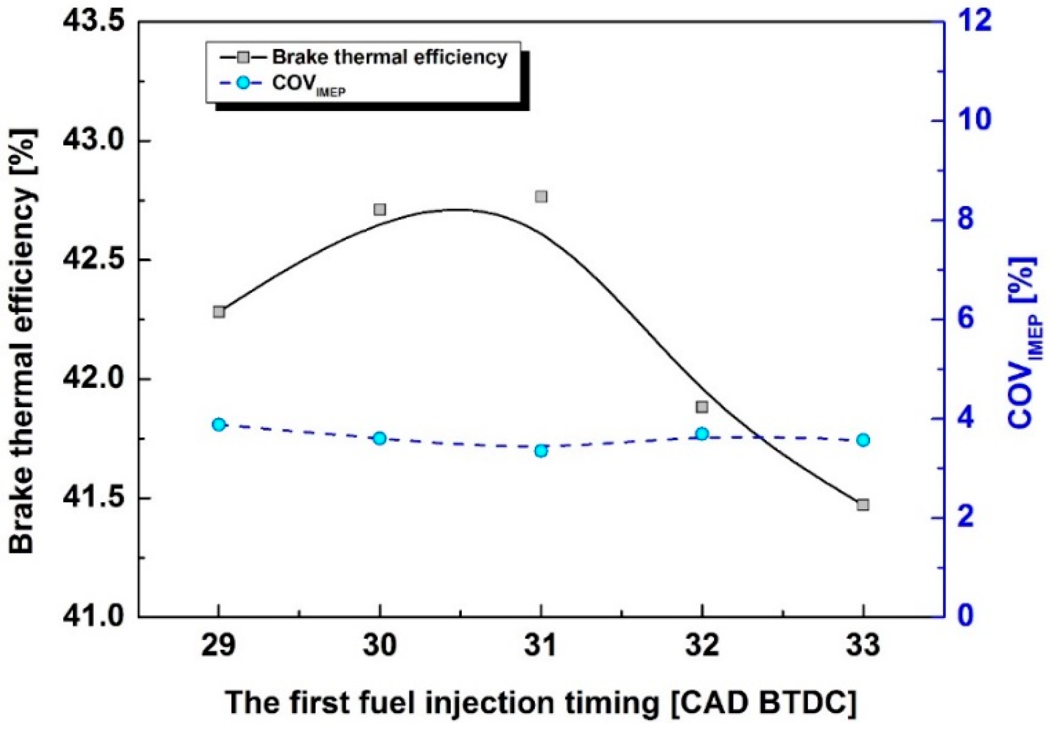
3.2. Effect of First Fuel Injection Timing on Efficiency and Combustion Stability

Because the combustion stability does not satisfy the standard for stable operation at the maximum thermal efficiency operation previously tested (i.e., at 27 CAD BTDC of SA timing), the effect of the first fuel injection timing was evaluated under a fixed SA and second fuel injection timing at 27 and 22 CAD BTDC respectively, as shown in Figure 4. The behavior of thermal efficiency and combustion stability is similar to the results obtained by changing SA timings. The advanced first fuel injection timing causes a stable combustion and decreases the thermal efficiency, whereas a delay in the first fuel injection destabilizes combustion and significantly decreases thermal efficiency. In particular, at a first fuel injection timing of 28 CAD BTDC, with only 1 CAD interval between the fuel injection and spark discharge, 27 CAD BTDC, there is insufficient time to form an ignitable stratified mixture before the ignition of the mixture through the spark discharge. Consequently, combustion destabilizes, resulting in lower thermal efficiency. The advanced first fuel injection timing results in a slight dispersion of fuel because of the time available before the spark discharge. In addition, the thermal efficiency decreases because the overly lean mixture caused by the dispersed fuel does not fully combust [22]. However, the flame initiation, which can affect the combustion stability, appears to be rather insensitive to the advance first fuel injection timing because the ignitable mixture is still present in the local recirculation zone proximal to the spark plug.
The abovementioned results show that combustion stability is not secured with variations in first fuel injection timing at maximum thermal efficiency of SA timing and 50%/50% fuel injection ratio. The change in the fuel injection ratio from 50%/50% to 60%/40% results in stable combustion. In addition, the brake thermal efficiency and COVIMEP were compared at 27 CAD BTDC of the fixed SA timing and 21 CAD BTDC of the second fuel injection timing, as shown in Figure 5. It is believed that the locally rich mixture region in the recirculation zone changes slightly because of the increase in the proportion of the injected first fuel, consequently improving combustion stability, regardless of first fuel injection timing. However, the utilization of fuel for combustion varies with the first fuel injection timing compared to the optimum timing, 29 CAD BTDC, at the fuel injection ratio of 50%/50%. The air utilization through air entrainment in the fuel spray is important to the propagation of flame after initiating a flame through spark discharge. Although the spray pattern change due to the variation in the amount of fuel injected is very small [22], a certain time is required for the air entrainment to form a stratified mixture. The experimental results show that the necessary time for mixture stratification is 3 CAD, 0.313 ms at 1600 rpm, for the fuel injection ratio of 60%/40%. The thermal efficiency decreases at a more advanced first fuel injection timing, such as 32 and 33 CAD BTDC, because of spray pattern change and fuel dispersion under lower ambient pressure conditions. The maximum brake thermal efficiency is 42.76% at the optimum operation point with a COVIMEP of 3.35%.

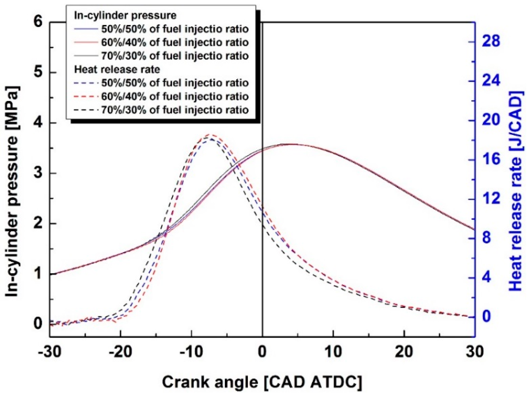
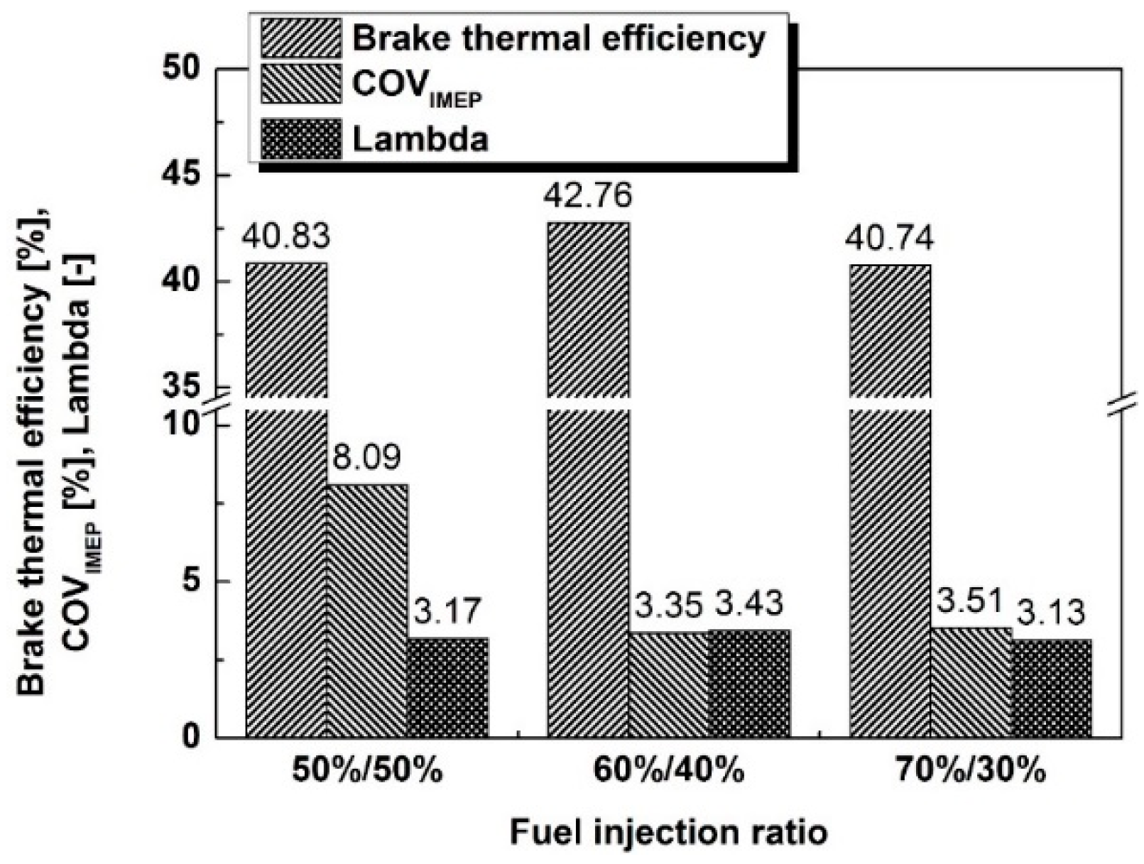
3.3. Effect of Fuel Injection Ratio on Efficiency and Combustion Stability

Figure 6 shows the comparison of the influence of fuel injection ratios of 50%/50%, 60%/40%, and 70%/30% on thermal efficiency and combustion stability. The SA timing for all the operation points was the same: 27 CAD BTDC. When the first fuel injection ratio is changed to 40% or 30%, the combustion is not sufficiently stable because the ignition of the smaller stratified mixture during spark discharge causes a partial burn or misfire, while a considerable amount of the second injected fuel could blow out the flame induced by the first fuel injection. As shown in Figure 5, a fuel injection ratio of 60%/40% demonstrates more stable combustion and consequently results in higher thermal efficiency. Given the wide-open throttle condition and the fixed values of both the engine speed and load, an increase in brake thermal efficiency implies the reduction in injected fuel mass, and accordingly an increase in the excess air ratio (Lambda).
The thermal efficiency of a 70%/30% fuel injection ratio is even lower than that of 50%/50%, and the COVIMEP is lower than the standard value at a stable operation. The reason may be inferred from the comparison graph of in-cylinder pressure traces and heat release rate, as shown in Figure 7. The increase in the amount of the first fuel injection leads to the formation of a richer stratified mixture in the recirculation zone in the proximity of the spark plug, and consequently promotes flame initiation. This is evidenced when the peak heat release for 70%/30% is most advanced, whereas the heat release after the peak is lowest because the propagation of the diffusion flame by the second injection decreases due to less injected fuel. Therefore, the combustion phase is the most advanced and deteriorated the thermal efficiency. The fuel injection ratio of 60%/40% is determined as the optimum fuel injection ratio at 1600 rpm and BMEP 0.24 MPa.

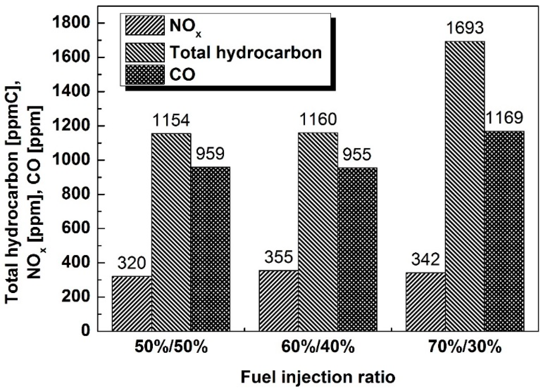
3.4. Effect of Fuel Injection Ratio on Engine Emissions

Figure 8 shows the comparison of the NOx, THC, and CO emissions for each fuel injection ratio condition. The stratified lean combustion is known to reduce NOx emissions by approximately 80% compared to the homogenous stoichiometric mixture combustion. This is because the ignitable rich mixture, which produces high temperature and NOx formation, exists only in the recirculation zone in the vicinity of the spark plug electrodes [16,28,29]. The flame propagation is improved by the small lean mixture of the first fuel injection and largely by the diffusion flame of the second fuel injection. The NOx emission for a 60%/40% fuel injection ratio was the highest because of higher heat release rate by flame initiation and consequently combustion temperature. The advanced combustion phase of a 70%/30% fuel injection ratio resulted in higher NOx than that of 50%/50%. The THC levels for 50%/50% and 60%/40% ratios were similar while that of 70%/30% was significantly higher. Although the excessive early fuel injection is not believed to be a significant issue at 60%/40%; at 70%/30%, it is expected to provide a source of fuel wetting on the cylinder walls and top surface of the piston. The formation of an overly lean mixture can be another reason for increased THC emissions. The CO emission behavior is very similar to that of THC emissions, and is consistent with the results of previous studies on lean mixture combustion [6,7,16,17,20,22,30].

4. Conclusions

In this study, we investigated the effect of the fuel injection ratio on combustion and emission characteristics of stratified lean mixture combustion in a spray-guided LPG direct-injection engine. A specially designed combustion strategy, called ISI combustion, for LPG fuel was employed from a two-staged injection to maximize the thermal efficiency when combustion stability is secured. While changing the fuel injection ratio, the optimum SA and fuel injection timings were experimentally determined at the best thermal efficiency throughout sweeping timings. The combustion and emission results for each fuel injection ratio were compared at optimal operating conditions. The main findings from this study are summarized as follows:
(1)
Although the combustion stability is secured through first fuel injection and spark discharge earlier than 29 and 27 CAD BTDC, respectively, at 50%/50% fuel injection ratio, the heat release does not efficiently translate to combustion power gains when the piston is moving upward to TDC.
(2)
The flame initiation, which can affect the combustion stability, is insensitive to the first fuel injection timing with advanced fuel injection and fixed SA timing condition because the ignitable mixture always exists within the local recirculation zone proximal to the spark plug.
(3)
The combustion stability is improved because of the locally rich mixture region in the recirculation zone with an increase in the proportion of the first fuel injected at a ratio of 60%/40%. The interval between the fuel injection and SA timing should be optimized because the time needed for entrained air to form a stratified mixture varies with the operating conditions and fuel injection ratio.
(4)
With a 70%/30% fuel injection ratio, the advanced combustion phase and faster heat release rate from the richer stratified mixture of the first fuel injection results in an overall deterioration of thermal efficiency.
(5)
The NOx emissions with a 60%/40% fuel injection ratio are the highest because of the highest combustion temperature. The THC and CO emissions for 50%/50% and 60%/40% are similar, whereas those for 70%/30% are significantly higher because of fuel wetting and the formation of an overly lean mixture.

Acknowledgments

Department of Engine Research is a multi-program laboratory managed and operated by Korea Institute of Machinery and Materials for the Korea Ministry of Science, ICT and Future Planning under contract NK197C.

Author Contributions

Cheolwoong Park and Taeyoung Kim conceived and designed the experiments; Taeyoung Kim performed the experiments; Cheolwoong Park and Gyubaek Cho analyzed the data; Janghee Lee contributed reagents/materials/analysis tools; Cheolwoong Park wrote the paper.

Conflicts of Interest

The authors declare no conflict of interest.

References

  1. Jobson, E. Future challenges in automotive emission control. Top. Catal. 2004, 28, 191–199. [Google Scholar] [CrossRef]
  2. Lenzen, E. Macondo Publishing GmbH. Global Compact International Yearbook 2015; Macondo Publishing: Münster, Germany, 2015. [Google Scholar]
  3. Demirbas, A. Fuel properties of hydrogen, liquefied petroleum gas (LPG), and compressed natural gas (CNG) for transportation. Energy Sources 2002, 24, 601–610. [Google Scholar]
  4. Boretti, A.A.; Watson, H.C. Development of a direct injection high efficiency liquid phase LPG spark ignition engine. SAE Int. J. Engines 2009, 2, 1639–1649. [Google Scholar] [CrossRef]
  5. Kim, J.; Choi, K.; Myung, C.L.; Park, S. Experimental evaluation of engine control strategy on the time resolved THC and nano-particle emission characteristics of liquid phase LPG direct injection (LPG-DI) engine during the cold start. Fuel Process. Technol. 2013, 106, 166–173. [Google Scholar] [CrossRef]
  6. Park, C.; Park, Y.; Oh, S.; Lee, Y.; Kim, T.Y.; Kim, H.; Choi, Y.; Kang, K.Y. Emission Characteristics of Gasoline and LPG in a Spray-Guided-Type Direct Injection Engine; SAE Technical Paper 2013-01-1323; SAE International: Warrendale, PA, USA, 2013. [Google Scholar]
  7. Park, C.; Park, Y.; Oh, S.; Lee, Y.; Kim, T.Y. Effect of Injection Timing Retard on ISI Strategy in Lean-Burning LPG Direct Injection Engines; SAE Technical Paper 2013-01-2636; SAE International: Warrendale, PA, USA, 2013. [Google Scholar]
  8. Stone, R. Introduction to Internal Combustion Engines; Palgrave Macmillan: Basingstoke, UK, 2012. [Google Scholar]
  9. Heywood, J.B. Internal Combustion Engine Fundamentals; McGraw-Hill: New York, NY, USA, 1988. [Google Scholar]
  10. Harada, J.; Tomita, T.; Mizuno, H.; Mashiki, Z.; Ito, Y. Development of Direct Injection Gasoline Engine; SAE Technical Paper 970540; SAE International: Warrendale, PA, USA, 1997. [Google Scholar]
  11. Iwamoto, Y.; Noma, K.; Nakayama, O.; Yamauchi, T.; Ando, H. Development of Gasoline Direct Injection Engine; SAE Technical Paper 970541; SAE International: Warrendale, PA, USA, 1997. [Google Scholar]
  12. Kuwahara, K.; Ueda, K.; Ando, H. Mixing Control Strategy for Engine Performance Improvement in a Gasoline Direct Injection Engine; SAE Technical Paper 980158; SAE International: Warrendale, PA, USA, 1998. [Google Scholar]
  13. Noguchi, M.; Sanda, S.; Nakamura, N. Development of Toyota Lean Burn Engine; SAE Technical Paper 760757; SAE International: Warrendale, PA, USA, 1976. [Google Scholar]
  14. Schwarz, C.; Schünemann, E.; Durst, B.; Fischer, J.; Witt, A. Potentials of the Spray-Guided BMW DI Combustion System; SAE Technical Paper 2006-01-1265; SAE International: Warrendale, PA, USA, 2006. [Google Scholar]
  15. Chang, W.S.; Kim, Y.N.; Kong, J.K. Design and Development of a Spray-Guided Gasoline DI Engine; SAE Technical Paper 2007-01-3531; SAE International: Warrendale, PA, USA, 2007. [Google Scholar]
  16. Park, C.; Kim, S.; Kim, H.; Moriyoshi, Y. Stratified lean combustion characteristics of a spray-guided combustion system in a gasoline direct injection engine. Energy 2012, 41, 401–407. [Google Scholar] [CrossRef]
  17. Park, C.; Kim, S.; Kim, H.; Lee, S.; Kim, C.; Moriyoshi, Y. Effect of a split-injection strategy on the performance of stratified lean combustion for a gasoline direct-injection engine. Proc. Inst. Mech. Eng. Part D 2011, 225, 1415–1426. [Google Scholar] [CrossRef]
  18. Peterson, B.; Reuss, D.L.; Sick, V. On the ignition and flame development in a spray-guided direct-injection spark-ignition engine. Combust. Flame 2014, 161, 240–255. [Google Scholar] [CrossRef]
  19. Piock, W.F.; Weyand, P.; Wolf, E.; Heise, V. Ignition systems for spray-guided stratified combustion. SAE Int. J. Engines 2010, 3, 389–401. [Google Scholar] [CrossRef]
  20. Myung, C.L.; Kim, J.; Choi, K.; Hwang, I.G.; Park, S. Comparative study of engine control strategies for particulate emissions from direct injection light-duty vehicle fueled with gasoline and liquid phase liquefied petroleum gas (LPG). Fuel 2012, 94, 348–355. [Google Scholar] [CrossRef]
  21. Myung, C.L.; Choi, K.; Kim, J.; Lim, Y.; Lee, J.; Park, S. Comparative study of regulated and unregulated toxic emissions characteristics from a spark ignition direct injection light-duty vehicle fueled with gasoline and liquid phase LPG (Liquefied Petroleum Gas). Energy 2012, 44, 189–196. [Google Scholar] [CrossRef]
  22. Park, C.; Oh, S.; Kim, T.; Oh, H.; Bae, C. Combustion characteristics of stratified mixture in lean-burn liquefied petroleum gas direct-injection engine with spray-guided combustion system. J. Eng. Gas Turbines Power 2015, 138, 071501. [Google Scholar] [CrossRef]
  23. Kajiwara, M.; Sugiyama, K.; Sagara, M.; Mori, M.; Goto, S.; Alam, M. Performance and Emissions Characteristics of an LPG Direct Injection Diesel Engines; SAE Technical Paper 2002-01-0869; SAE International: Warrendale, PA, USA, 2002. [Google Scholar]
  24. Lee, S.; Kusaka, J.; Daisho, Y. Mixture Formation and Combustion Characteristics of Directly Injected LPG Spray; SAE Technical Paper 2003-01-1917; SAE International: Warrendale, PA, USA, 2003. [Google Scholar]
  25. Kim, T.; Park, C.; Oh, S.; Cho, G. The effect of stratified lean combustion and exhaust gas recirculation on combustion and emission characteristics of an LPG direct injection engine. Energy 2016, 115, 386–396. [Google Scholar] [CrossRef]
  26. Baecker, H.; Kaufmann, A.; Tichy, M. Experimental and Simulative Investigation on Stratification Potential of Spray-Guided GDI Combustion Systems; SAE Technical Paper 2007-01-1407; SAE International: Warrendale, PA, USA, 2007. [Google Scholar]
  27. Kim, S.; Kim, Y.; Lee, J. Analysis of the In-Cylinder Flow, Mixture Formation and Combustion Processes in a Spray-Guided GDI Engine; SAE Technical Paper 2008-01-0142; SAE International: Warrendale, PA, USA, 2008. [Google Scholar]
  28. Oh, H.; Bae, C. Effects of the injection timing on spray and combustion characteristics in a spray-guided DISI engine under lean-stratified operation. Fuel 2013, 107, 225–235. [Google Scholar] [CrossRef]
  29. Gong, C.M.; Huang, K.; Jia, J.L.; Su, Y.; Gao, Q.; Liu, X.J. Regulated emissions from a direct-injection spark-ignition methanol engine. Energy 2011, 36, 3379–3387. [Google Scholar] [CrossRef]
  30. Oh, S.; Lee, S.; Choi, Y.; Kang, K.Y.; Cho, J.; Cha, K. Combustion and Emission Characteristics in a Direct Injection LPG/Gasoline Spark Ignition Engine; SAE Technical Paper 2010-01-1461; SAE International: Warrendale, PA, USA, 2010. [Google Scholar]
Figure 1. Schematic of a combustion chamber with the location of the spark plug and fuel injector.
Energies 09 00920 g001
Figure 2. Variations in brake thermal efficiency and combustion stability with 27 and 19 CAD BTDC of fuel injection and 25 CAD BTDC of SA timing at an operation point of 1500 rpm and BMEP of 0.15 MPa, and with an spark advance (SA) timing change at the operation point of 1600 rpm and BMEP of 0.24 MPa.
Energies 09 00920 g002
Figure 3. In-cylinder pressure traces and heat release rates for 1500 rpm with BMEP of 0.15 MPa and 25 CAD BTDC of SA timing for 1600 rpm and BMEP of 0.24 MPa; and 25 and 27 CAD BTDC of SA timings.
Energies 09 00920 g003
Figure 4. Variations in brake thermal efficiency and combustion stability according to the change in the first fuel injection timing with fuel injection ratio of 50%/50% and fixed second fuel injection and SA timing at 1600 rpm and BMEP of 0.24 MPa.
Energies 09 00920 g004
Figure 5. Variations in brake thermal efficiency and combustion stability according to the change in the first fuel injection timing with a fuel injection ratio of 60%/40% and fixed second fuel injection and SA timing at 1600 rpm and BMEP of 0.24 MPa.
Energies 09 00920 g005
Figure 6. The comparison of brake thermal efficiency, combustion stability, and excess air ratio (Lambda) for the fuel injection ratios of 50%/50%, 60%/40%, and 70%/30% with the optimized first fuel injection timing and SA timing of 27 CAD BTDC at 1600 rpm and BMEP of 0.24 MPa.
Energies 09 00920 g006
Figure 7. Comparison of in-cylinder pressure traces and heat release rate for the fuel injection ratio of 50%/50%, 60%/40%, and 70%/30% with optimized fuel injection and SA timing at 1600 rpm and BMEP of 0.24 MPa.
Energies 09 00920 g007
Figure 8. Comparison of NOx, THC, and CO emissions for 50%/50%, 60%/40%, and 70%/30% fuel injection ratios with optimized fuel injection and SA timing at 1600 rpm with BMEP of 0.24 MPa.
Energies 09 00920 g008
Table 1. Specifications of the test engine.
ParameterSpecifications
Displaced volume1988 cc
Stroke86 mm
Bore86 mm
Connecting rod255 mm
Compression ratio10:1
Number of valves4
Exhaust valve timingBBDC 7 CAD/ATDC 67 CAD 1
Intake valve timingBTDC 48 CAD/ABDC 0 CAD 2
1 BBDC: before bottom dead center, CAD: crank angle degree, ATDC: after top dead center; 2 BTDC: before top dead center, ABDC: after bottom dead center.
Table 2. Controlled combustion parameter for each operating condition.
Operating Point (Speed and Load a)Fuel Injection RatioFirst Fuel Injection TimingSpark Advance TimingSecond Fuel Injection Timing
1500 rpm
0.15 MPa
50%/50%27 CAD BTDC25 CAD BTDC20 CAD BTDC
1600 rpm
0.24 MPa
50%/50%28–33 CAD BTDC25–31 CAD BTDC20–26 CAD BTDC
60%/40%23–33 CAD BTDC21–27 CAD BTDC17–21 CAD BTDC
70%/30%32 CAD BTDC27 CAD BTDC23 CAD BTDC
a Load in BMEP (brake mean effective pressures).

