
A Novel Flux Focusing Magnetically Geared Machine with Reduced Eddy Current Loss

Abstract
:1. Introduction
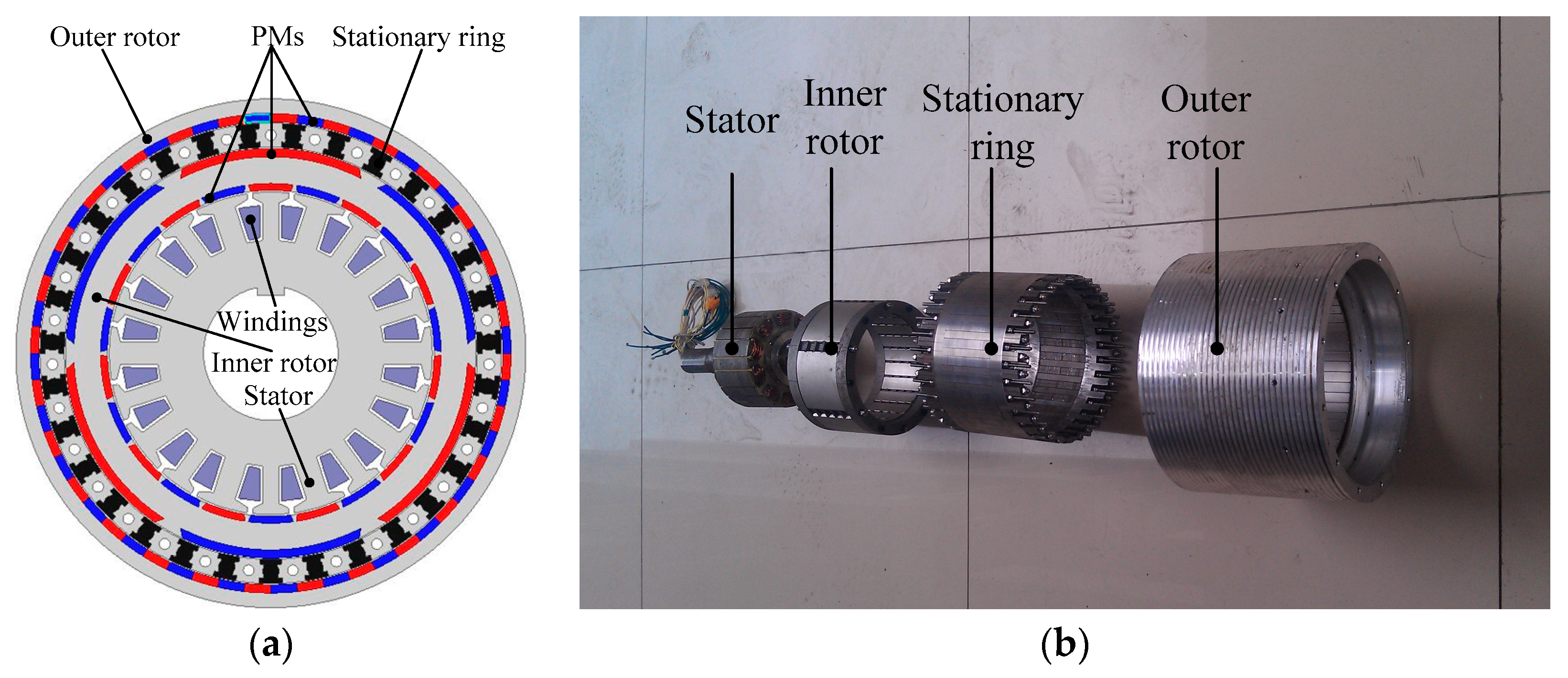
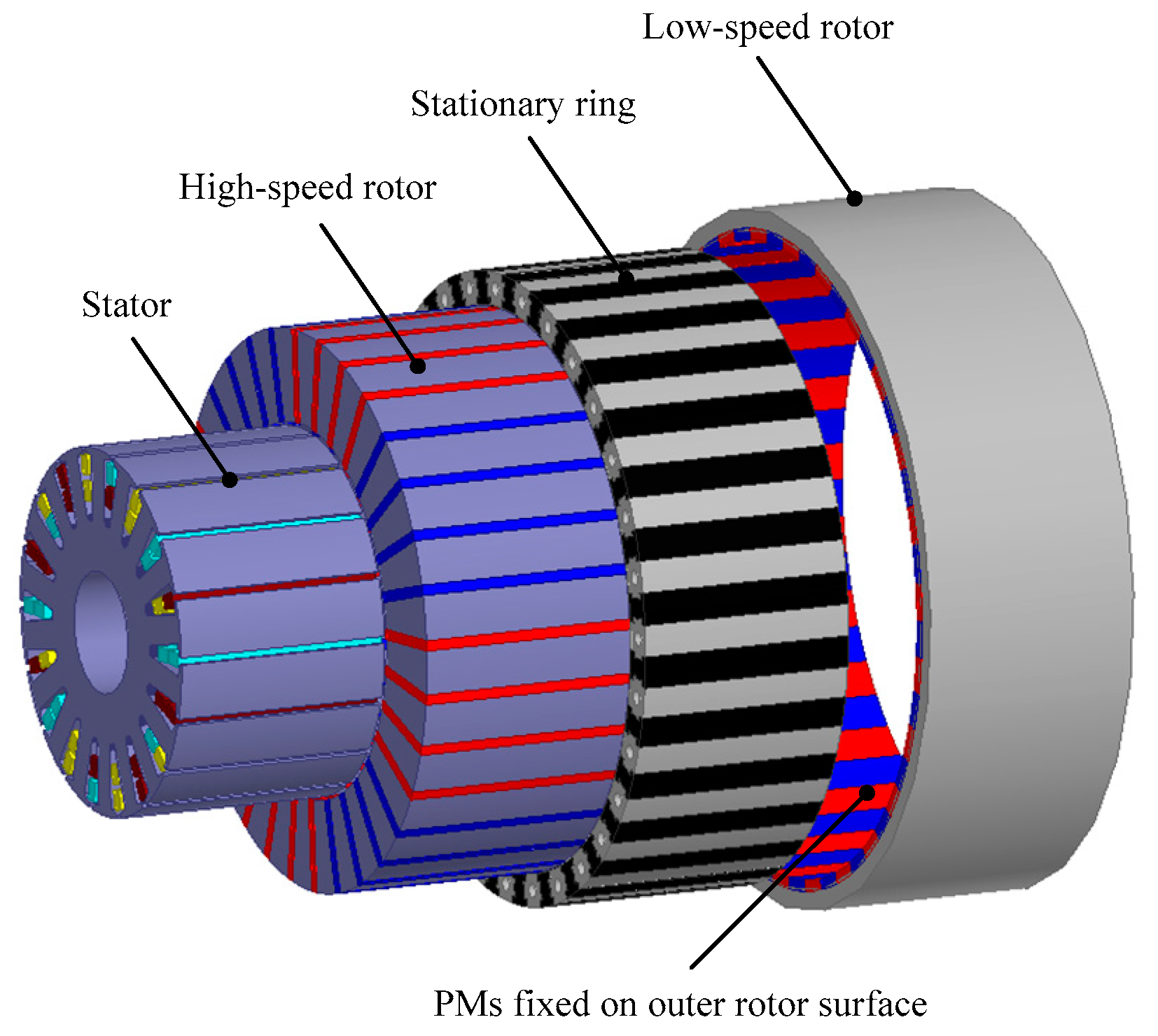
2. Topology and Loss Analysis
3. Parameters Optimization
3.1. Optimization Goal
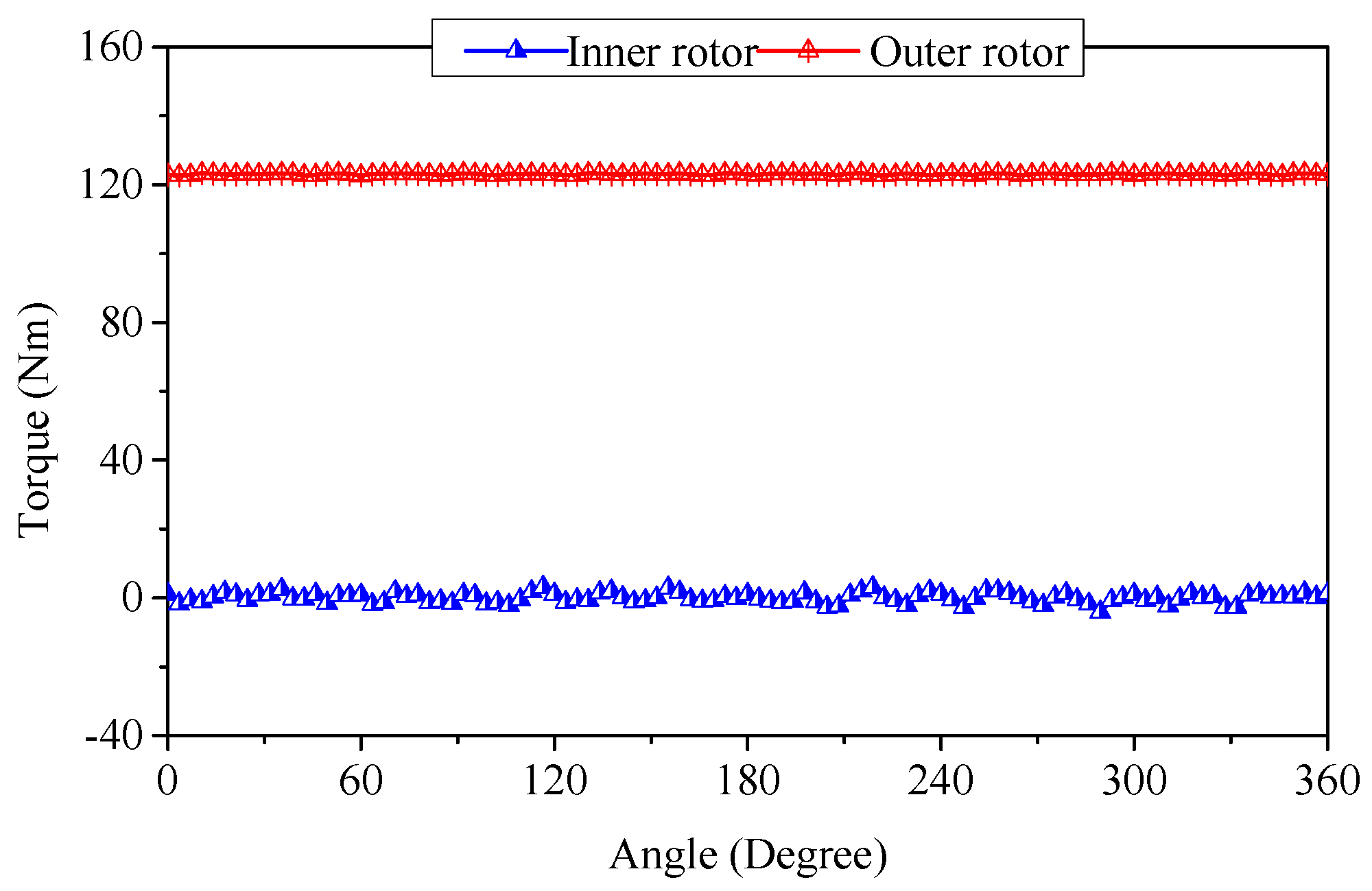
- The magnetic torque results from the magnetic gearing action of the high-speed rotor and the low-speed rotor, just like in magnetic gear.
- The electromagnetic torque is generated, primarily, as a consequence of interaction between the high-speed rotor and the field generated by the stator windings as in PM brushless machine.
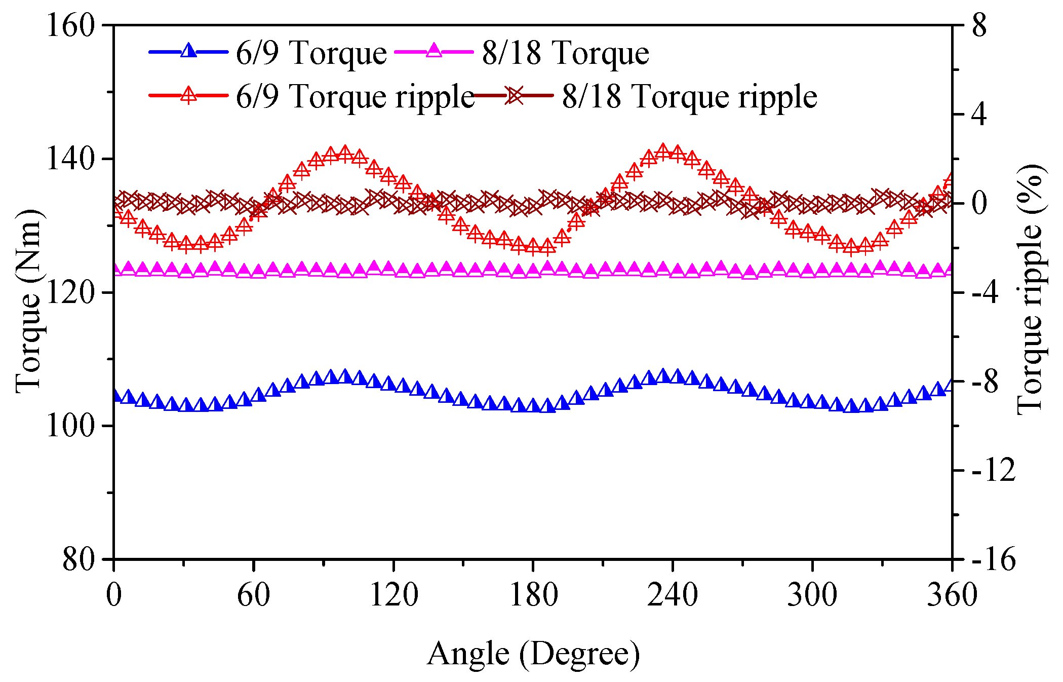
3.2. Pole-Slot Selection
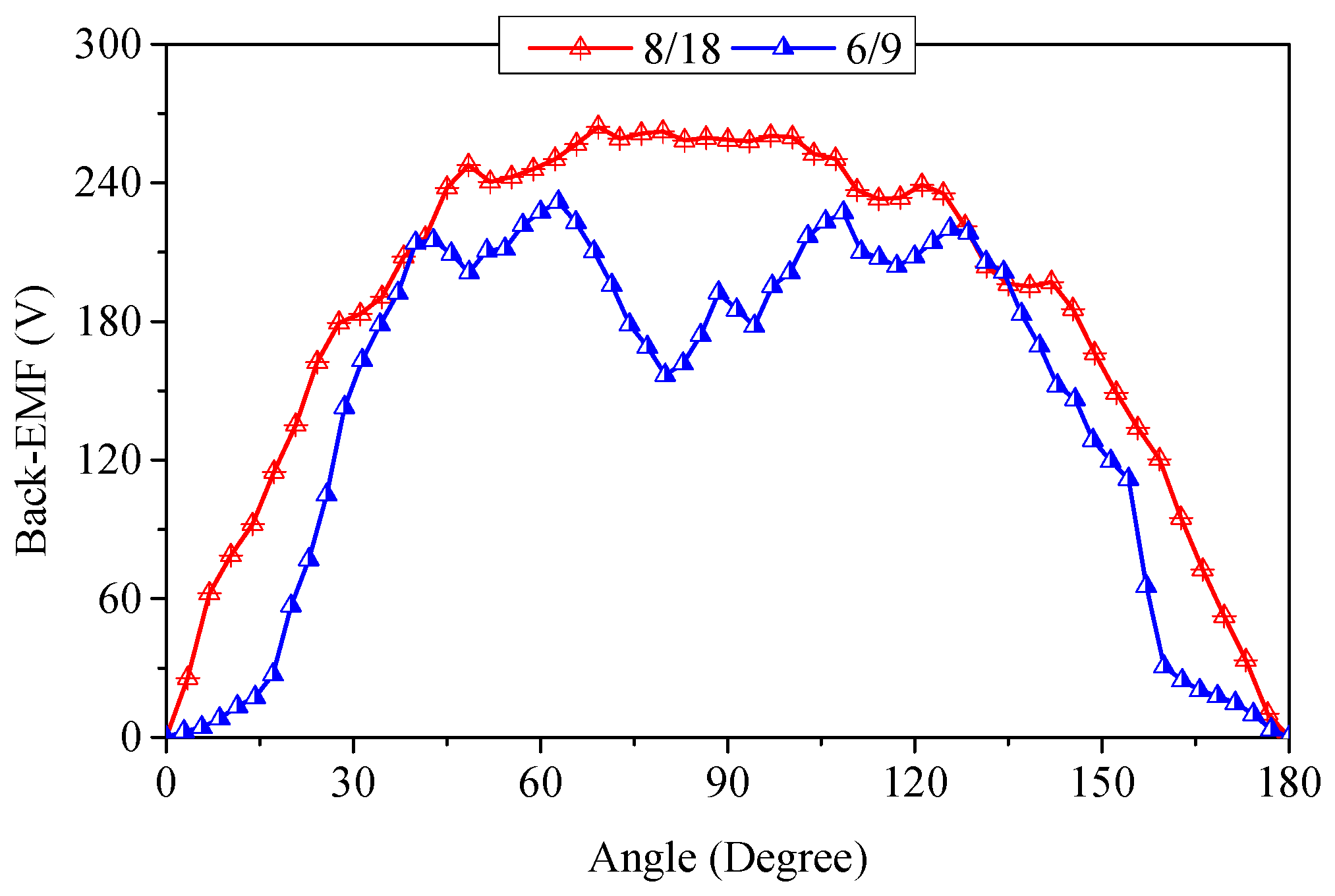
- For the same Pl number, the 8/18 combination invariably gives higher torque than the 6/9 combination due to the increased Gr.
- The MG machines with higher stator slots can be realized with a lower torque ripple.
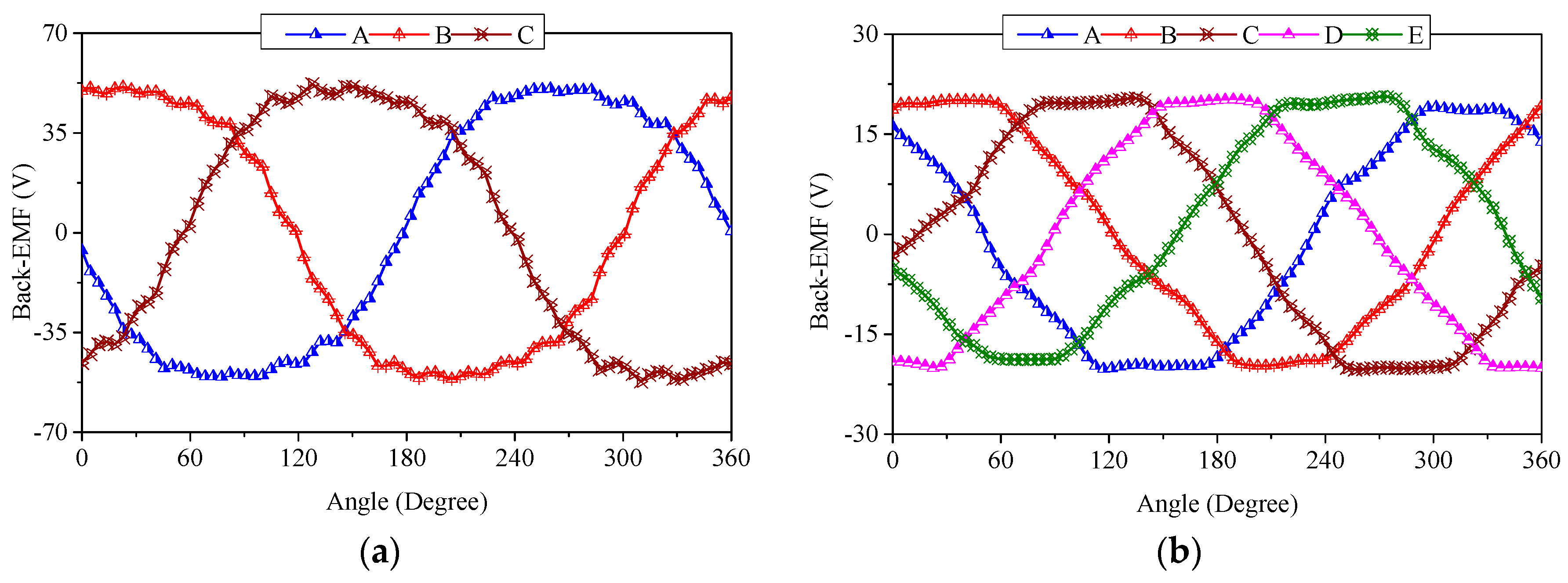
- The higher stator slots can alleviate wave distortion and offer high peak values of the back-EMFs.
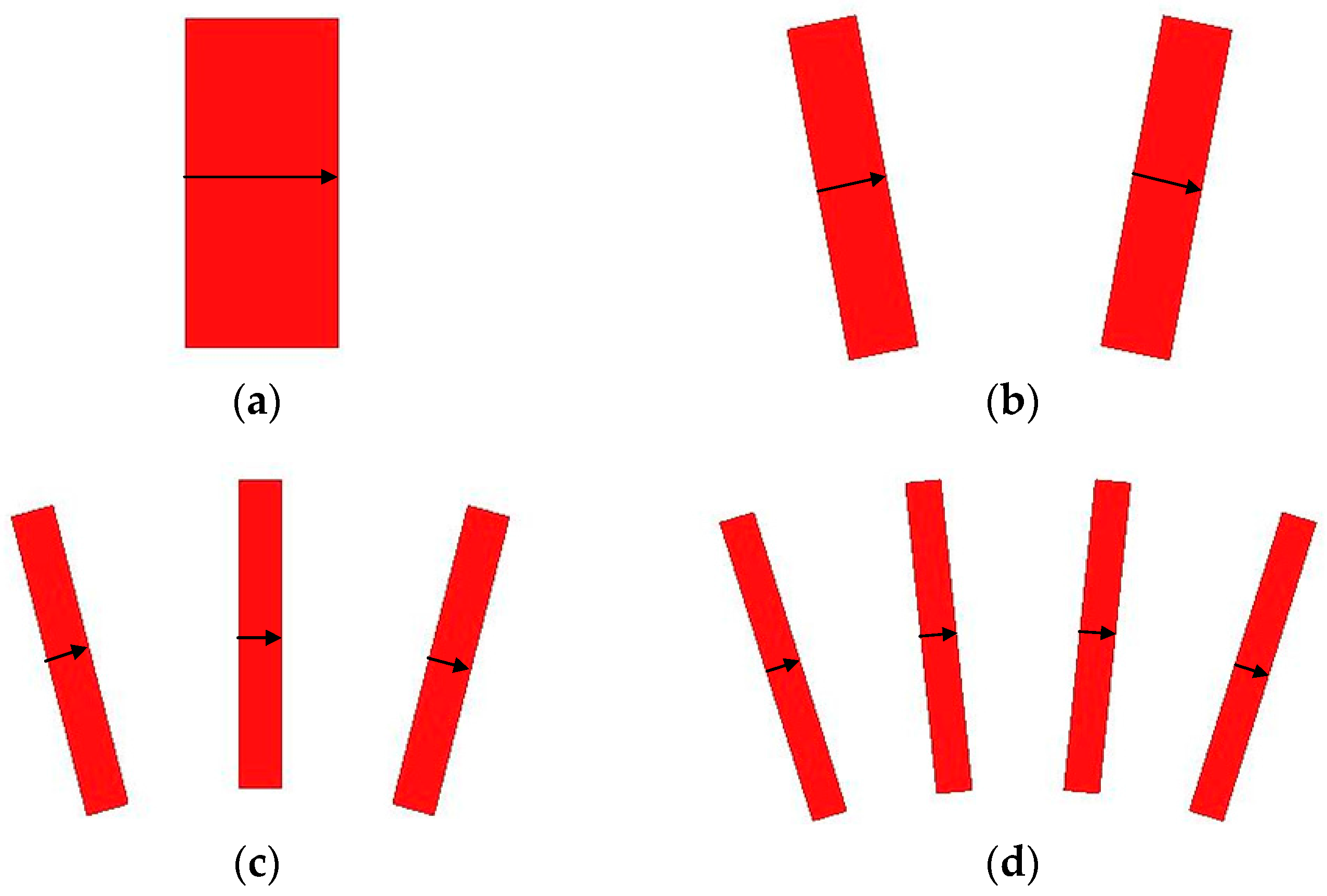
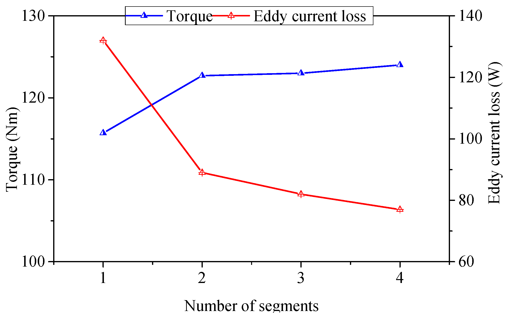
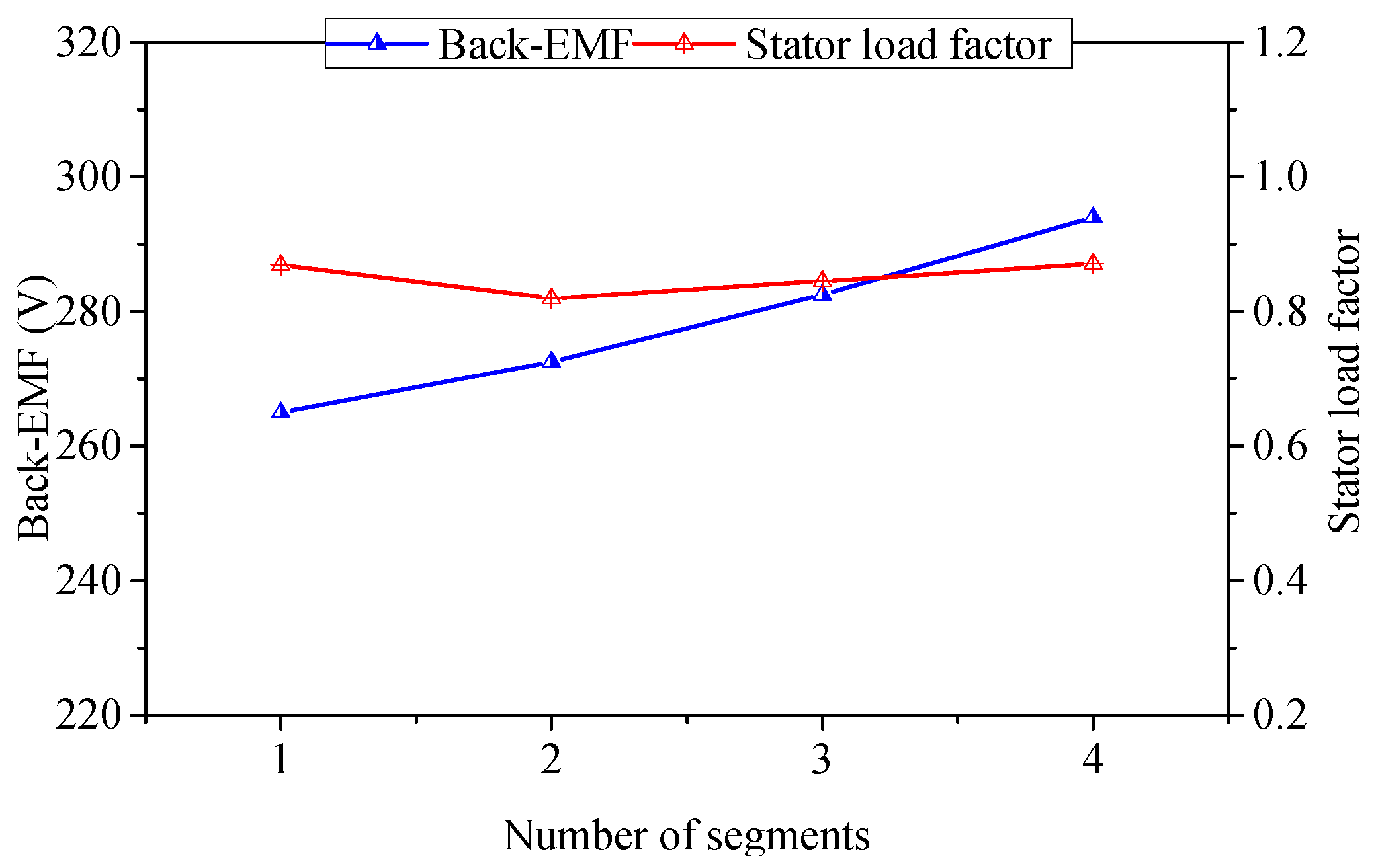
3.3. Spoke Serial Number Selection
3.4. Final Design
4. Performance Evaluation
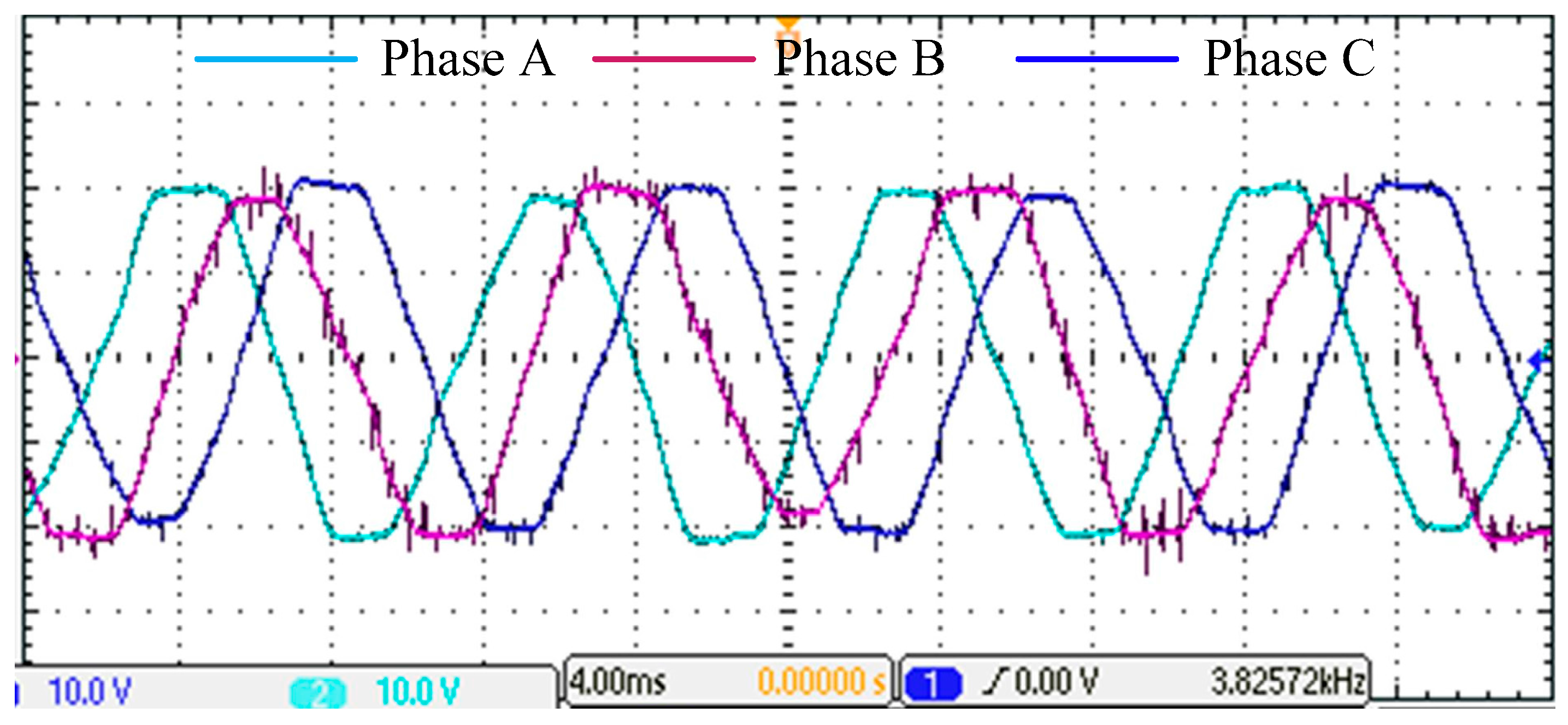
4.1. Back-EMF
4.2. Torque
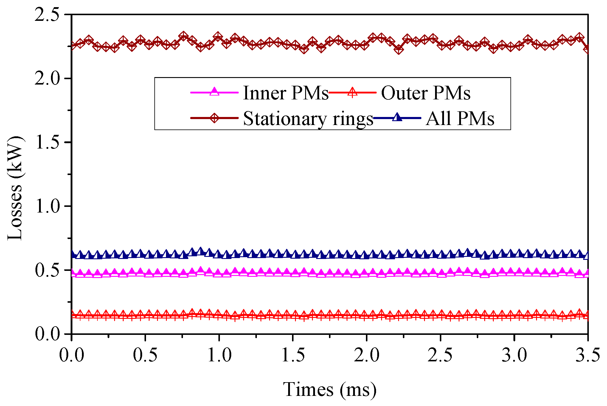
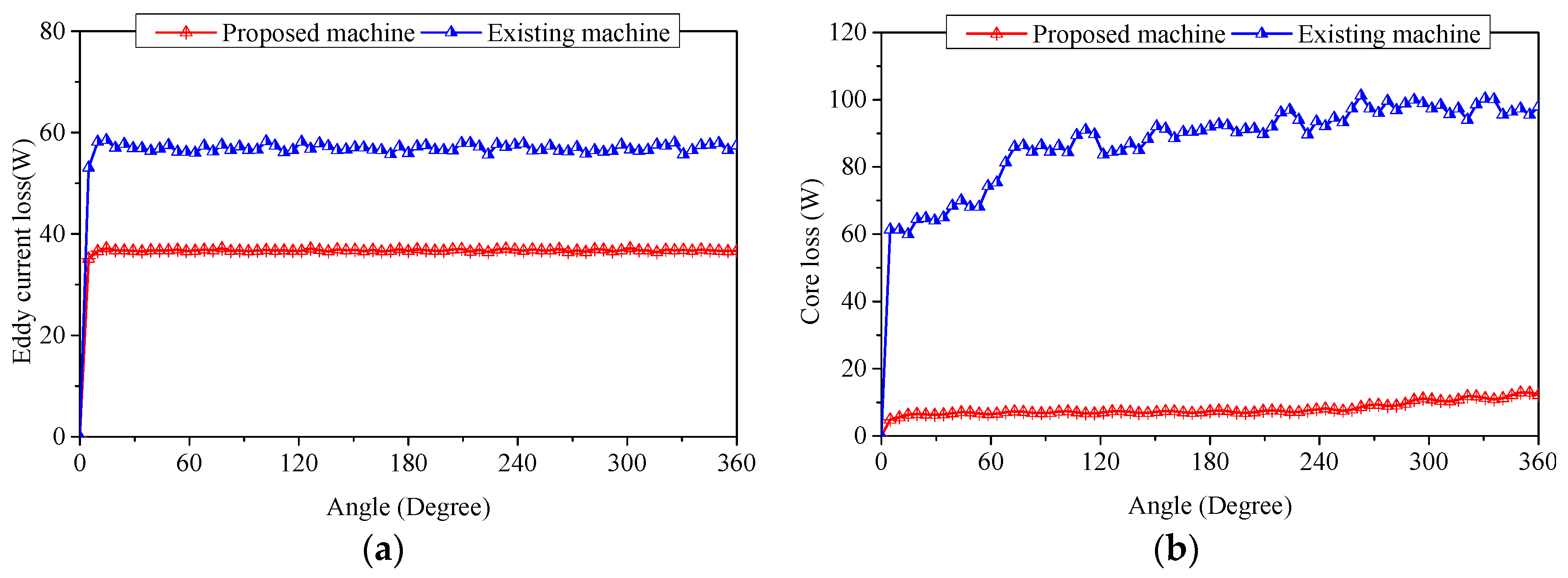
4.3. Loss And Effeciency
4.4. Comparison
5. Conclusions
Acknowledgments
Author Contributions
Conflicts of Interest
References
- Duong, M.; Grimaccia, F.; Leva, S.; Mussetta, M.; Le, K. Improving transient stability in a grid-connected squirrel-cage induction generator wind turbine system using a fuzzy logic controller. Energies 2015, 8, 6328–6349. [Google Scholar] [CrossRef] [Green Version]
- Wang, D.; Liu, C.; Li, G. An optimal integrated control scheme for permanent magnet synchronous generator-based wind turbines under asymmetrical grid fault conditions. Energies 2016, 9, 307. [Google Scholar] [CrossRef]
- Shin, H.; Park, K.; Lee, K. A non-unity torque sharing function for torque ripple minimization of switched reluctance generators in wind power systems. Energies 2015, 8, 11685–11701. [Google Scholar] [CrossRef]
- Beik, O.; Schofield, N. An offshore wind generation scheme with a high-voltage hybrid generator, HVDC interconnections, and transmission. IEEE Trans. Power Deliv. 2016, 31, 867–877. [Google Scholar] [CrossRef]
- Wang, R.J.; Brönn, L.; Gerber, S.; Tlali, P.M. Design and evaluation of a disc-type magnetically geared PM wind generator. In Proceedings of the 2013 4th International Conference on Power Engineering, Energy and Electrical Drives (POWERENG), Istanbul, Turkey, 13–17 May 2013; pp. 1259–1264.
- Chau, K.T.; Zhang, D.; Jiang, J.Z. Design of a magnetic-geared outer-rotor permanent-magnet brushless motor for electric vehicles. IEEE Trans. Magn. 2007, 43, 2504–2506. [Google Scholar] [CrossRef] [Green Version]
- Rashidi, H.; Pishdad, D. Integrated multispeed magnetic gears: A novel approach to design of magnetic transmission systems. IEEE Trans. Magn. 2014, 51, 1–8. [Google Scholar] [CrossRef]
- Zhao, W.; Liu, J.; Ji, J.; Liu, G.; Ling, Z. Comparison of coaxial magnetic gears with and without magnetic conducting ring. IEEE Trans. Appl. Supercond. 2016, 26, 1–5. [Google Scholar] [CrossRef]
- Atallah, K.; Howe, D. A novel high-performance magnetic gear. IEEE Trans. Magn. 2001, 37, 2844–2846. [Google Scholar] [CrossRef]
- Liu, C.; Chau, K.T. Electromagnetic design of a new electrically controlled magnetic variable-speed gearing machine. Energies 2014, 7, 1539–1554. [Google Scholar] [CrossRef] [Green Version]
- Shin, H.M.; Chang, J.H. Analytical magnetic field calculation of coaxial magnetic gear with flux concentrating rotor. IEEE Trans. Magn. 2016, 52, 1–4. [Google Scholar] [CrossRef]
- Zhang, X.; Liu, X.; Wang, C.; Chen, Z. Analysis and design optimization of a coaxial surface-mounted permanent-magnet magnetic gear. Energies 2014, 7, 8535–8553. [Google Scholar] [CrossRef]
- Ho, S.L.; Wang, Q.; Niu, S.; Fu, W.N. A novel magnetic-geared tubular linear machine with halbach permanent-magnet arrays for tidal energy conversion. IEEE Trans. Magn. 2015, 51, 1–4. [Google Scholar]
- Chen, Y.; Fu, W. A novel hybrid-flux magnetic gear and its performance analysis using the 3-D finite element method. Energies 2015, 8, 3313–3327. [Google Scholar] [CrossRef]
- Chen, M.; Chau, K.T.; Li, W.; Liu, C.; Qiu, C. Design and analysis of a new magnetic gear with multiple gear ratios. IEEE Trans. Appl. Supercond. 2014, 24. [Google Scholar] [CrossRef]
- Feng, N.; Yu, H.; Hu, M.; Liu, C.; Huang, L.; Shi, Z. A study on a linear magnetic-geared interior permanent magnet generator for direct-drive wave energy conversion. Energies 2016, 9, 487. [Google Scholar] [CrossRef]
- Peng, S.; Fu, W.N.; Ho, S.L. A novel high torque-density triple-permanent-magnet-excited magnetic gear. IEEE Trans. Magn. 2014, 50, 1–4. [Google Scholar] [CrossRef]
- Jing, L.; Liu, L.; Xiong, M.; Feng, D. Parameters analysis and optimization design for a concentric magnetic gear based on sinusoidal magnetizations. IEEE Trans. Appl. Supercond. 2014, 24, 1–5. [Google Scholar] [CrossRef]
- Wang, L.; Shen, J.; Luk, P.C.K.; Fei, W.; Wang, C.; Hao, H. Development of a magnetic-geared permanent-magnet brushless motor. IEEE Trans. Magn. 2009, 45, 4578–4581. [Google Scholar] [CrossRef] [Green Version]
- Zhang, Y.Q.; Lu, K.Y.; Ye, Y.Y. Permanent magnet eddy current loss analysis of a novel motor integrated permanent magnet gear. IEEE Trans. Magn. 2012, 48, 3005–3008. [Google Scholar] [CrossRef]
- Tian, Y.; Liu, G.H.; Zhao, W.X.; Ji, J.H. Design and analysis of coaxial magnetic gear considering rotor losses. In Proceedings of the 2015 IEEE Magnetics Conference (INTERMAG), Beijing, China, 11–15 May 2015; pp. 1–4.
- Rasmussen, P.O.; Andersen, T.O.; Joergensen, F.T.; Nielsen, O. Development of a high-performance magnetic gear. IEEE Trans. Ind. Appl. 2005, 41, 764–770. [Google Scholar] [CrossRef]
- Liu, G.; Jiang, Y.; Ji, J.; Chen, Q.; Yang, J. Design and analysis of a new fault-tolerant magnetic-geared permanent-magnet motor. IEEE Trans. Appl. Supercond. 2014, 24. [Google Scholar] [CrossRef]
- Huang, W.Y.; Bettayeb, A.; Kaczmarek, R.; Vannier, J.C. Optimization of magnet segmentation for reduction of eddy-current losses in permanent magnet synchronous machine. IEEE Trans Energy Convers. 2010, 25, 381–387. [Google Scholar] [CrossRef]
- Gerber, S.; Wang, R.J. Design and evaluation of a magnetically geared pm machine. IEEE Trans. Magn. 2015, 51, 1–10. [Google Scholar] [CrossRef]


| Parameters | Value | Units |
|---|---|---|
| Outer rotor outside radius rs_out | 94.7 | mm |
| Stationary ring outside radius rs_in | 85.7 | mm |
| Inner rotor outside radius rs_s | 76 | mm |
| Stator radius yoke ry | 17 | mm |
| Stator radius rs | 50.5 | mm |
| Length of air gap tbrg | 0.5 | mm |
| PMs material | Nd-Fe-B | – |
| Magnet remanence | 1.23 | T |
| Grades of steel | 0.35 mm silicon steel | – |
| Parameters | Value | Units |
|---|---|---|
| Number of stator slots | 18 | – |
| Number of pole-pairs on inner rotor | 4 | – |
| Number of segments | 4 | – |
| Number of pole-pairs on outer rotor | 27 | – |
| Number of stationary rings | 31 | – |
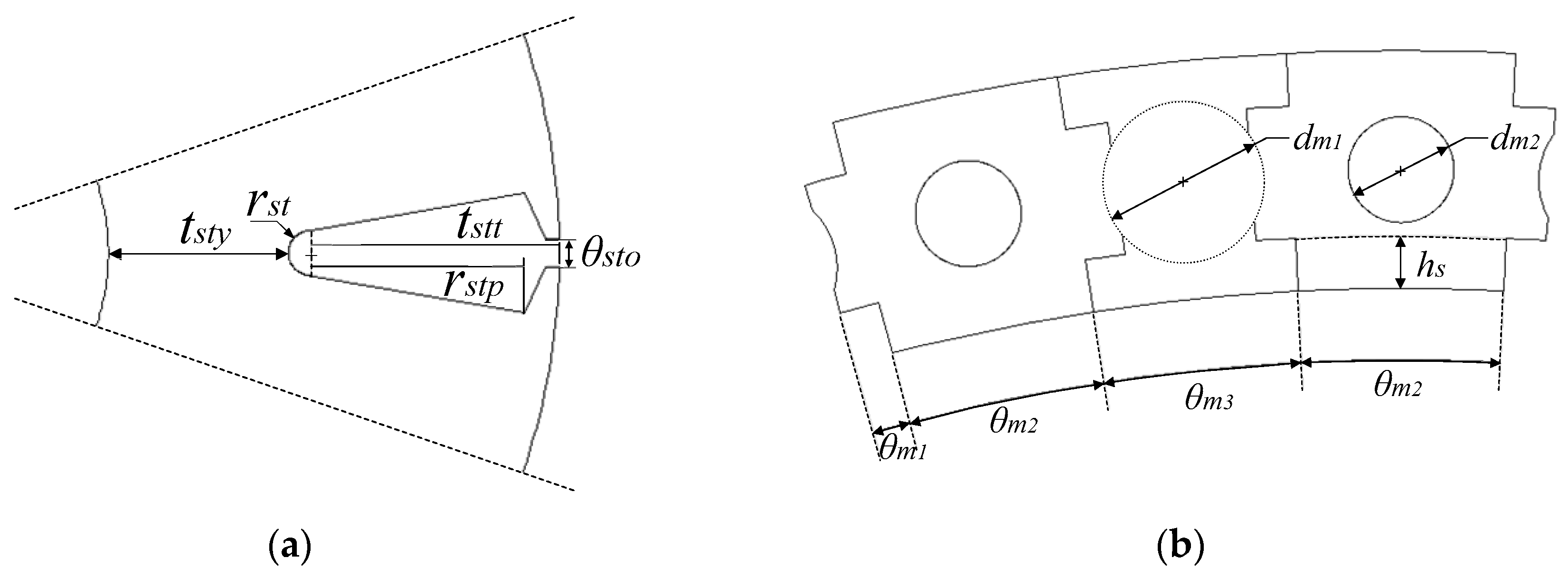
| Stator tooth thickness tstt | 18.4 | mm |
| Slot tip rstp (fraction of tooth thickness) | 0.86 | – |
| Slot opening θsto (fraction of slot pitch) | 0.12 | – |
| Stator yoke thickness tsty | 13.3 | mm |
| Stator parameter rst | 1.66 | mm |
| Length of inner rotor PMs tmh | 25 | mm |
| Thickness of inner rotor PMs hm | 2.75 | mm |
| Rotor magnet span to pole embrace θs2/θs1 | 0.89 | – |
| Stationary ring parameter θm1 | 1.1 | ° |
| Stationary ring span to pole embrace θm2/θm3 | 1 | – |
| Stationary ring parameter dm1 | 4 | mm |
| Stationary ring parameter dm2 | 6 | mm |
| Stationary ring parameter hs | 2 | mm |
| Thickness of outer rotor PMs trm | 3 | mm |
| Thickness of outer rotor yoke try | 5.5 | mm |
| Stack length | 60 | mm |
| Descriptions | Existing | Proposed |
|---|---|---|
| Torque (Nm) | 123.7 | 122.3 |
| Volume (L) | 1.64 | 1.64 |
| Torque density (kNm/m3) | 76 | 75.1 |
| Eddy current loss (W) | 57 | 37 |
| Core loss (W) | 100 | 13 |
| Stator load factor | 0.91 | 0.85 |
| Efficiency (%) | 90 | 94 |
| Power factor | 0.93 | 0.93 |
| Operating speed (r/min) | 1200 | 1200 |
© 2016 by the authors; licensee MDPI, Basel, Switzerland. This article is an open access article distributed under the terms and conditions of the Creative Commons Attribution (CC-BY) license (http://creativecommons.org/licenses/by/4.0/).
Share and Cite
Liu, J.; Zhao, W.; Ji, J.; Liu, G.; Tao, T. A Novel Flux Focusing Magnetically Geared Machine with Reduced Eddy Current Loss. Energies 2016, 9, 904. https://doi.org/10.3390/en9110904
Liu J, Zhao W, Ji J, Liu G, Tao T. A Novel Flux Focusing Magnetically Geared Machine with Reduced Eddy Current Loss. Energies. 2016; 9(11):904. https://doi.org/10.3390/en9110904
Chicago/Turabian StyleLiu, Jin, Wenxiang Zhao, Jinghua Ji, Guohai Liu, and Tao Tao. 2016. "A Novel Flux Focusing Magnetically Geared Machine with Reduced Eddy Current Loss" Energies 9, no. 11: 904. https://doi.org/10.3390/en9110904