Article

Auto-Mapping and Configuration Method of IEC 61850 Information Model Based on OPC UA

1
Department of Electrical Engineering, Korea University, Seoul 02841, Korea
2
Department of Electrical Engineering, Seokyeong University, Seoul 02173, Korea
*
Author to whom correspondence should be addressed.
Energies 2016, 9(11), 901; https://doi.org/10.3390/en9110901
Submission received: 24 June 2016 / Revised: 9 October 2016 / Accepted: 20 October 2016 / Published: 1 November 2016
(This article belongs to the Special Issue Advances in Power System Operations and Planning)

Abstract

:
The open-platform communication (OPC) unified architecture (UA) (IEC62541) is introduced as a key technology for realizing a variety of smart grid (SG) use cases enabling relevant automation and control tasks. The OPC UA can expand interoperability between power systems. The top-level SG management platform needs independent middleware to transparently manage the power information technology (IT) systems, including the IEC 61850. To expand interoperability between the power system for a large number of stakeholders and various standards, this paper focuses on the IEC 61850 for the digital substation. In this paper, we propose the interconnection method to integrate communication with OPC UA and convert OPC UA AddressSpace using system configuration description language (SCL) of IEC 61850. We implemented the mapping process for the verification of the interconnection method. The interconnection method in this paper can expand interoperability between power systems for OPC UA integration for various data structures in the smart grid.

1. Introduction

In the energy field, smart grids are a much-discussed topic. Many views on smart grids exist, which has led to many definitions of what is understood as a smart grid [1,2]. Power information technology (IT) protocols have a complicated network configuration because of the presence of a variety of protocols. The open-platform communication (OPC) unified architecture (UA) (IEC62451) middleware has a simple network configuration because it can be integrated into a single protocol. OPC UA is the communication protocol for the smart grid (SG) application platform. It was standardized by the IEC TC57 group in December 2008. The abstract approach of the OPC UA enables extensions of the application area, so the focus is on general data exchange within any domain, and it can be used for integrated automation concerns [3,4,5].
The IEC 61850 is the communication protocol and the substation’s service model. It has been used in digital substation systems and smart distributed systems. The top-level SG management platform needs independent middleware to transparently manage power IT systems. Interconnection modules between power IT and OPC UA in the top-level SG management system have to be developed to manage the supervisory control and data acquisition (SCADA) protocol [6,7,8].
In this contribution, we focus on communication technology mappings of the IEC 61850 and introduce the OPC UA as an alternative way of communication based on the IEC 61850 model. We designed mapping between OPC UA AddressSpace and IEC 61850 model information using UA’s UaModeler. We implemented System Configuration description Language (SCL) for the OPC UA AddressSpace module. We converted all the SCL files to the OPC UA AddressSpace. We verified IEC 61850 model mapping onto OPC UA using KEMA’s UniCA IED (level A certificate) Server Simulator.
OPC UA was developed using UA’s UaModeler and a C++-based system development kit. The IEC 61850 client module was developed using SISCO’s MMS-EASE Lite library, and the IEC 61850 server was using KEMA’s UniCA IED (intelligent electronic device) simulator.
The paper is organized as follows. In Section 2.1 and Section 2.2, we discuss Power IT Protocols—the OPC UA (IEC62451) and IEC 61850 standards. In Section 2.3 and Section 2.4, we outline the IEC 61850 model mapping onto OPC UA. Section 3 outlines the experimental results and performance evaluation. Section 4 concludes the paper and shows some future perspectives.

2. IEC 61850 Model Mapping onto OPC UA

2.1. OPC UA (IEC62451) Standard

OPC UA (IEC62451) was standardized by the IEC TC57 group in December 2012. The classic OPC was separated into OPC Data Access (DA), OPC Historical Data Access (HDA), OPC Alarms & Conditions (AC), and OPC Extensible Markup Language (XML). The classic OPC features were integrated into OPC UA. Additionally, service-oriented architecture (SOA) was added to OPC UA [3].
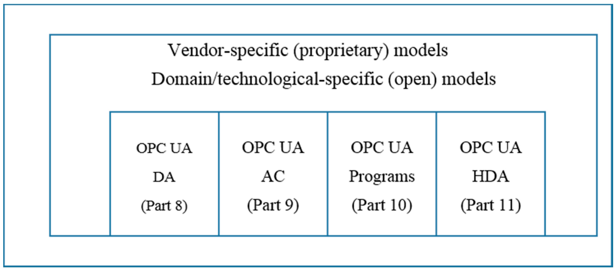
The information model of integrated OPC UA is shown in Figure 1 [4]. The classic OPC can be built on top of the OPC UA-based information model. Vendor-specific models and domain/technology-specific models can be built on top of the OPC UA-based information model and the classic OPC, exposing their specific information via OPC UA. OPC UA AddressSpace, provided by OPC UA, is defined along with general information models based on object type. All information models using OPC UA define the following: (i) the entry points into the address space used by clients to navigate through the instances and types of OPC UA servers; (ii) the base types that build the root for the different types of hierarchies; (iii) the built-in but extensible types (i.e., object types and data types); and (iv) the server object that provides capability and diagnostic information. OPC UA information models, as well as complex models, can provide simple information. The base modeling concepts of OPC UA are nodes and references between nodes. Each node contains attributes, such as ID and name.
OPC UA software layers are shown in Figure 2. The complete software stack can be implemented with C, .Net, or JAVA. OPC UA is not limited to these programming languages and development platforms, however, only these environments are currently used for implementing the OPC foundation UA stack deliverables [9].
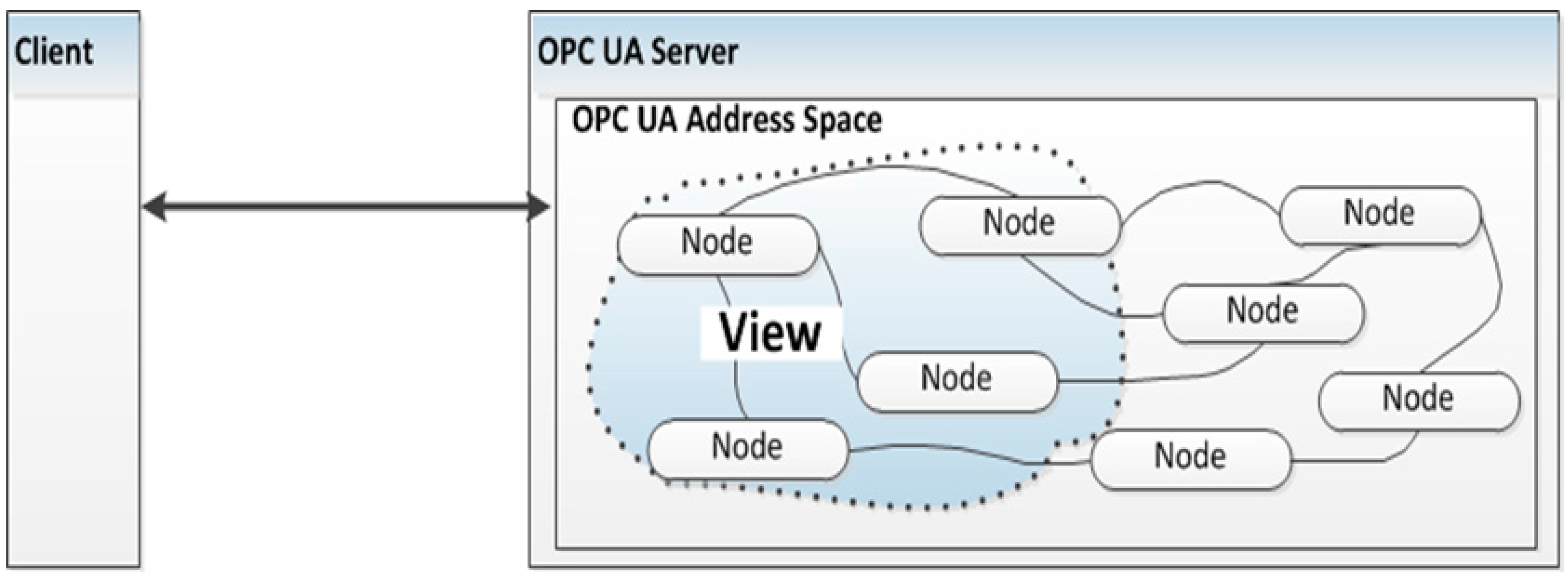
Figure 3 shows the OPC UA AddressSpace. The AddressSpace model specifies the building blocks to expose instance and type information and thus the OPC UA meta-model used to describe and expose information models and to build the OPC UA server AddressSpace. The OPC UA AddressSpace is modeled as a set of nodes that are accessible by OPC UA clients using OPC UA services. The nodes in the AddressSpace are used to represent real objects, their definitions, and their references to each other. The view is a specific subset of the AddressSpace that is of interest to the OPC UA clients [10].

2.2. IEC 61850 Standard

IEC 61850 is a communication standard for electrical substation automation systems. It is the standard protocol used in digital substation systems and smart distributed systems. The goal of the IEC 61850 series is to provide interoperability between the IEDs from different suppliers or, more precisely, between functions to be performed by systems for power utility automation while residing in equipment from different suppliers. IEC 61850-7 describes the relationships between other parts of the IEC 61850 series [11].
The models of the Abstract Communication Service Interface (ACSI) provide [12]:
  • The definition of the basic model of the utility information models contained in IEC 61850-7-3 (common data classes for utility automation applications), IEC 61850-7-4 (compatible logical node classes and compatible data classes for utility automation applications), and IEC 61850-6 (the substation configuration language).
  • The definition of information exchange service models.
The following overall classes are defined: Server, Logical Device, Logical Node, and Data Object.
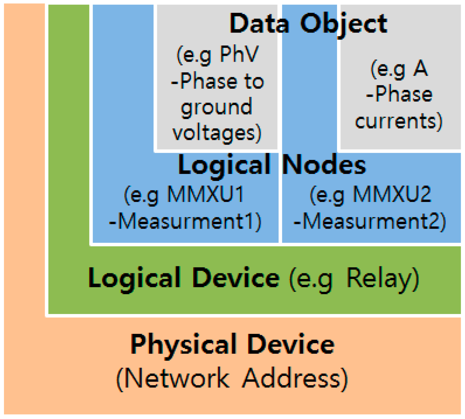
The IEC 61850 information model is shown in Figure 4. The information model is an abstract representation of the devices inside the substation. The logical devices (LDs) comprise a virtual representation of physical devices, such as relays or bays in the substation. An LD includes many logical nodes (LNs). LNs are virtual representations of components of devices, such as switches, circuit breakers, and voltage meters. Data objects (DOs) are representations of the common information of nodes. All devices follow a common naming scheme; even if the manufacturer is different, it is possible to access the same device. DOs are typed by common data classes (CDC) from IEC 61850-7-3 or IEC 61850-7-2 [12,13].
Functional constraints (FC) play a crucial role in the definition of the information models and in the services used to access the various parts of the information model. The FC is not shown in the object reference. The FC information may be mapped into the object reference in a Specific Communication Service Mapping; IEC 61850-8-1 maps the FC between the logical node name and the data name (Relay1:MMXU1$CF$PhV). FCs are defined as follows: MX—measurements; ST—status; CF—configuration; RP—unbuffered report control blocks; LG—log control blocks; BR—buffered report control blocks; GO—Generic Oriented Object System Event (GOOSE) control blocks; GS—Generic Substation Status Event (GSSE) control blocks; SV—substituted values; SE—setting group editing [14].
The language for the configuration of electrical substation IEDs is called System Configuration description Language (SCL) [15]. It is used to describe IED configurations and communication systems according to IEC 61850-5 and IEC 61850-7. It allows the formal description of the relations between the utility automation system and the process (substation, switchyard).
Table 1 shows all the groups in the logical node defined in IEC 61850-7-4 [16]. This group is defined as approximately 90 logical nodes, such as the common applications and supply of substation equipment. One major focus is the definition of information models for applications relating to the Protection and Protection-related. The two groups constitute almost half of the logical node. This shows the high importance of the Protection for the safety and stable operation of the power system.

2.3. Design of OPC UA AddressSpace for IEC 61850

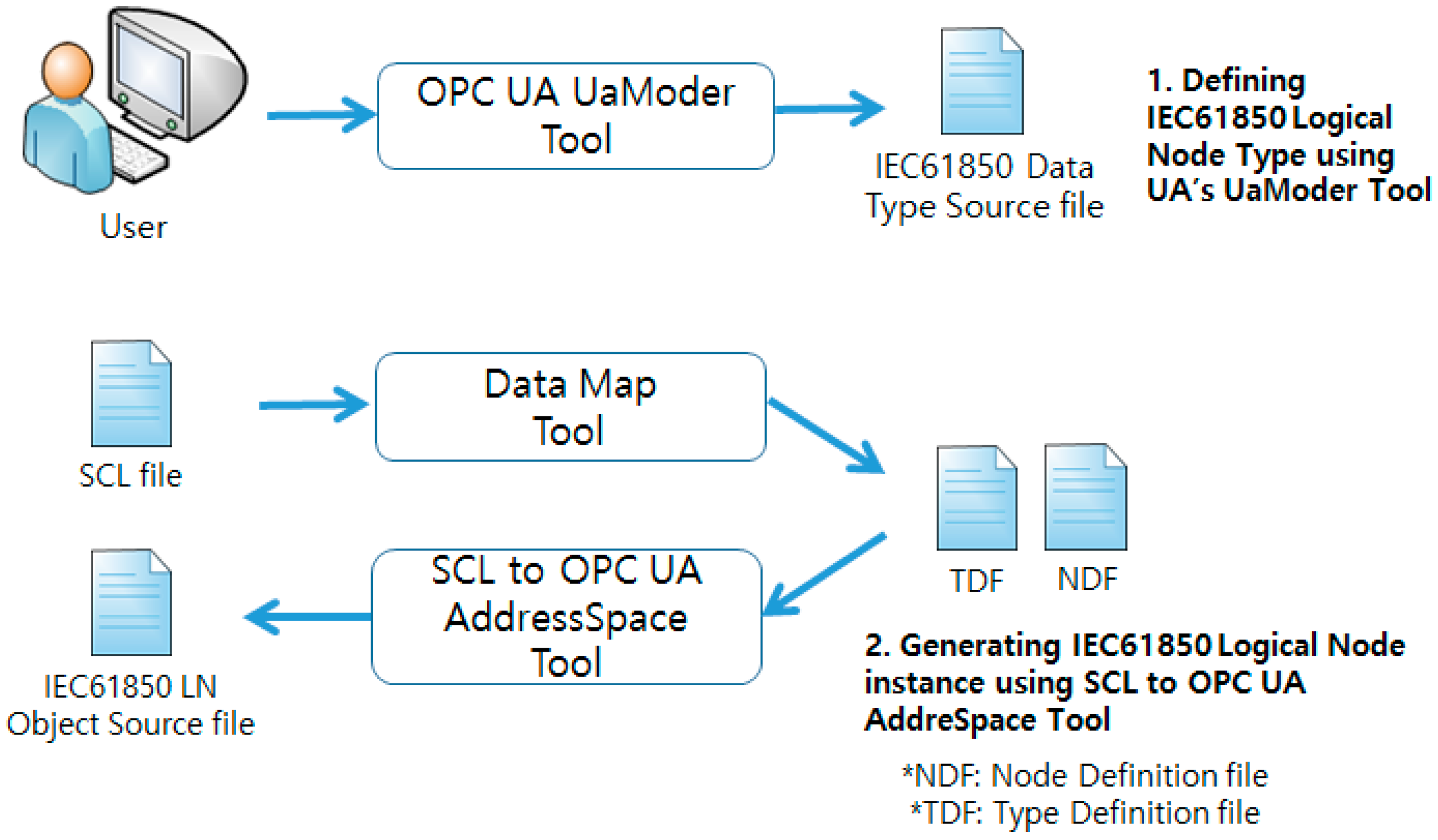
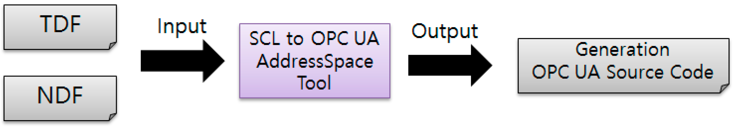
Figure 5 shows the whole design flow of OPC UA AddressSpace for IEC 61850. First, the engineer has to define IEC 61850 logical node type using UA’s UaModeler—Section 2.3. Second, the user needs to generate IEC 61850 logical node instance using SCL to OPC UA AddressSpace Tool—Section 2.4. IEC 61850 logical node type source file and IEC 61850 logical node instance source file represent the IEC 61850 information in OPC UA.
OPC UA provides extensible information models. The information models of OPC UA are mapped after generating the abstract object on AddressSpace. Therefore, the IEC 61850 information model has to be modeled onto OPC UA AddressSpace. The following describes how the IEC16850 is mapped to the OPC UA AddressSpace.
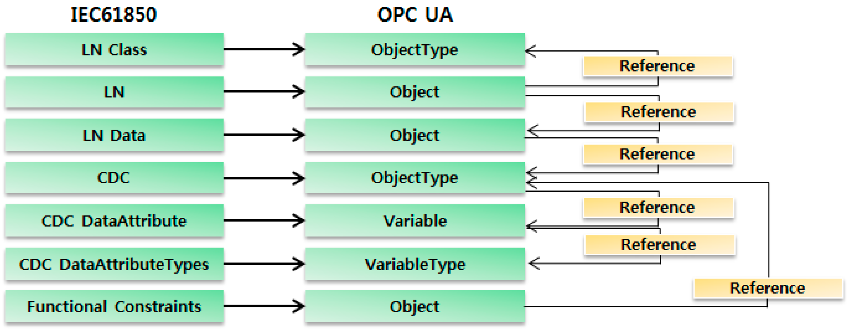
The mapping of the IEC 61850 information model onto OPC UA AddressSpace is shown in Figure 6 [1]. The OPC UA AddressSpace changes the model from the IEC 61850 information to the IEC62541 information. Then, it has and holds as nodes on AddressSpace.
To structure the objects, three standard UA reference types are used [2]:
-
HasComponent describes part of the relationship between LN and its attributes as well as between CDC and its attributes. Furthermore, it is used for the grouping by FC.
-
Organizes is used to group the CDC attributes by FC.
-
HasTypeDefinition connects the LN attributes with the according CDC.
Mapping example: The model of the XCBR, one of the logical nodes (LNs) of the IEC 61850, using UA’s Modeler tool can be mapped by reference to Figure 5. The XCBR LN of the IEC 61850 is the circuit breaker (CB) of the substations or distributed devices [12]. It is mapped to object type because of the LN class. Additionally, it has many common data classes (CDCs) of the attribute type [11]. CDCs are modeled to object type. CDCs reference the LN data defined in the IEC 61850. The Single Point Status (SPS), one of the CDCs, provides status information. The quality of the measured value (q) and the timestamp of the measured value (t) are modeled to the variable [11]. The predefined data type is referred to in Modeler. The XCBR LN has LN data: Loc (local control behavior), EEHealth (external equipment health), EEName (external equipment name plate), and so forth, as the HasComponent. The HasComponent ReferenceType is used, exposing the configuration of a device as a component of the device. The attribute types of LN refer to the CDC, such as SPS to HasTypeDefinition [1,10].
Data-type mapping is the most basic information in the rules of mapping. IEC 61850 BasicTypes are consistent with OPC UA BaseDataTypes. Table 2 shows the data-type mapping table for mapping the IEC 61850 and OPC UA.
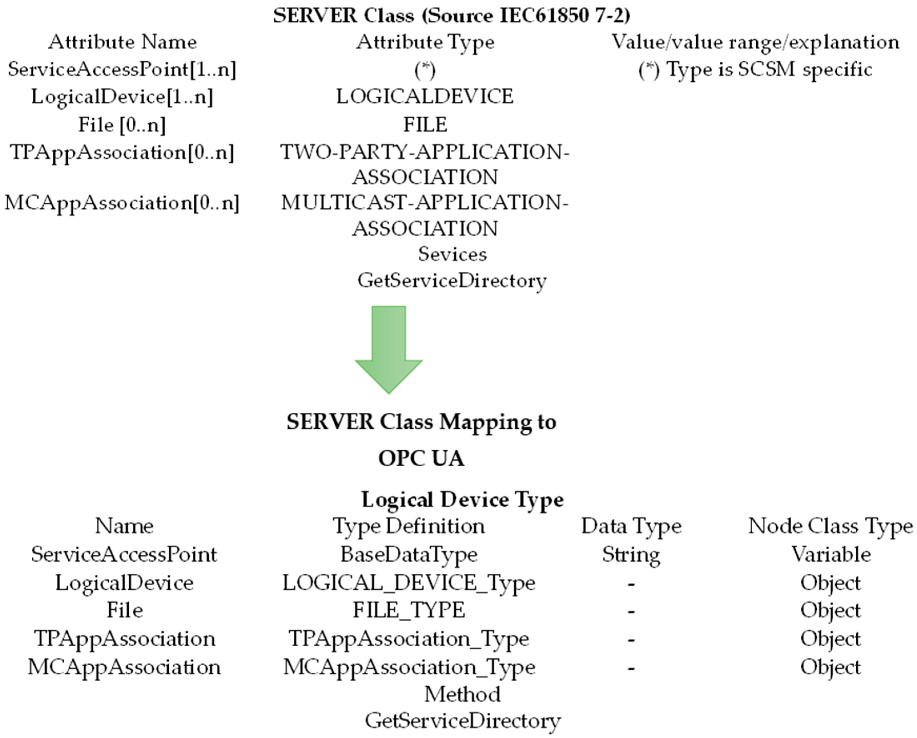
Figure 7 shows ACSI server class mapping. The server class represents the external visible behavior of a device. It is composed of 1 to N logical device classes. The attribute ServiceAccessPoint identifies a server within the scope of a subnetwork. The attribute LogicalDevice identifies a logical device that is contained in a general server. The attribute File identifies a file system included in a general server. The attribute TPAppAssociation identifies a client with which a server maintains a two-party application association. The attribute MCAppAssociation identifies a subscriber with which a server maintains a multicast application association. ServiceAccessPoint is mapped to the variable node class type. The remaining attributes are mapped to the object node class type [6,10,12].
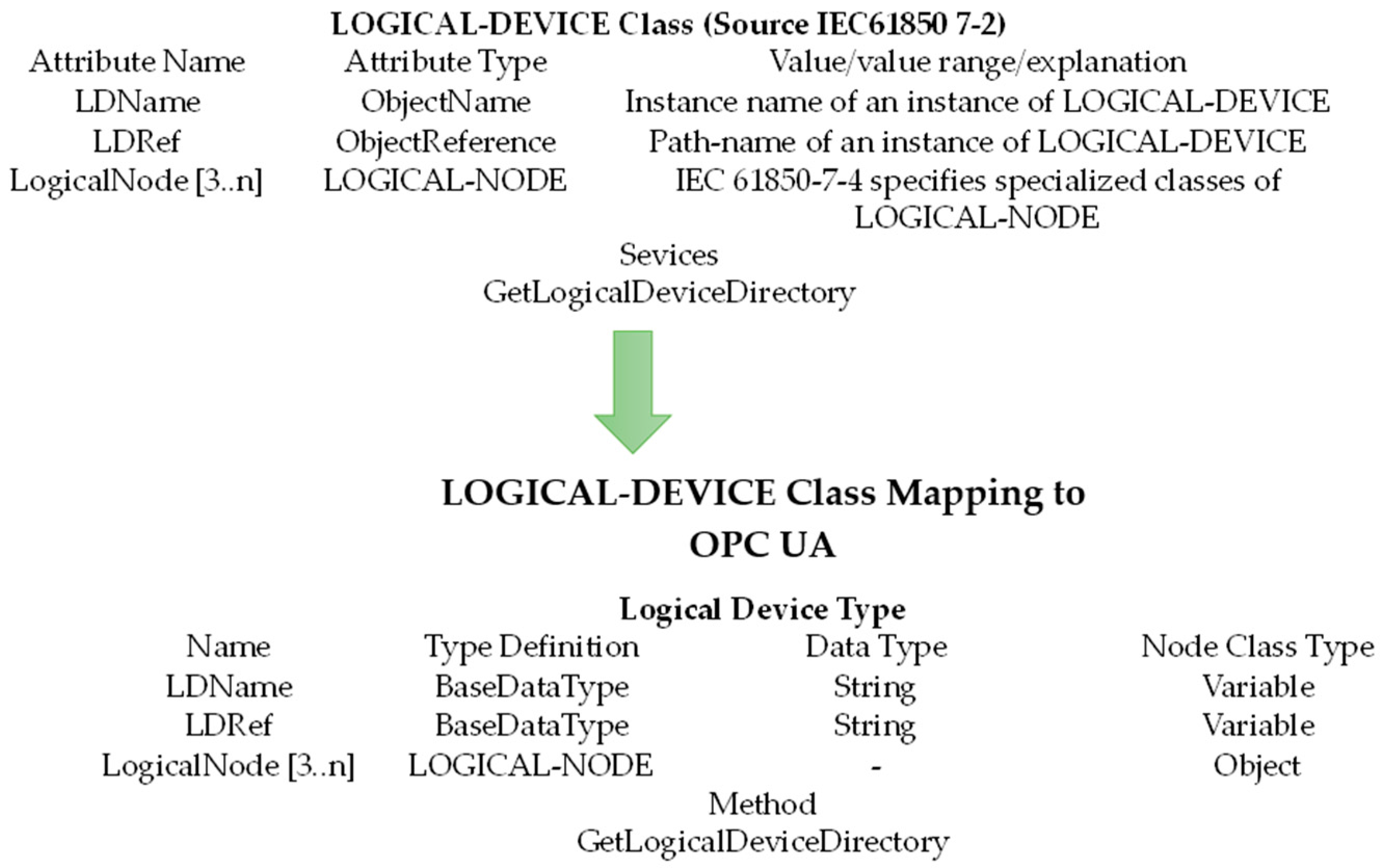
ACSI logical device mapping is shown in Figure 8. The logical device classes comprise three or more logical node classes. The attribute LDName unambiguously identifies an instance of a logical device within the scope of a subnetwork. The attribute LDRef identifies the reference path of a logical device within the scope of a subnetwork. The attribute LogicalNode is a list of all logical nodes that are contained in a general logical device class. LDName and LDRef are mapped to the variable Node class type. LogicalNode is mapped to the object node class type.
The ACSI logical node class is a composition of LNName, LNRef, DataObjects, DATA-SET, BRCB (buffered report control block), and URCB (unbuffered report control block) [9]. The attribute LNName unambiguously identifies a logical node within the scope of a logical device. The attribute LNRef is the unique path name of a logical node. The attribute DataObject is a data object contained in a logical node. The attribute DataSet is a list of all data sets that are included in a logical node. The attribute BRCB is a list of all buffered report control blocks that are comprised in a logical node. The attribute URCB is a list of all unbuffered report control blocks that are contained in a logical node. LNName and LNRef are mapped to the variable node class type. The remaining attributes are mapped to the object node class type.
The ACSI data object class is a key element in IEC 61850. It is a composition of DataObjectName, DataObjectRef, and DataObjectType. The attribute DataObjectName unambiguously identifies a data object within the scope of a logical node. The attribute DataObjectRef is the unique path name of a data object. The DataObjectType is the CDC type.
Table 3 shows an example of the common data class (CDC—Data Object). The CDCs are defined in IEC 61850-7-3 [13]. CDCs are a configured common data attribute (base data type or data structure) and they are defined for use in IEC 61850-7-4 [16]. CDCs define the relation between their attributes and the functional constraint as well as the possible trigger options. CDC specifications are classified as status, measurand, controls, status settings, analog settings, and description. DPS (double point status) belongs to status.
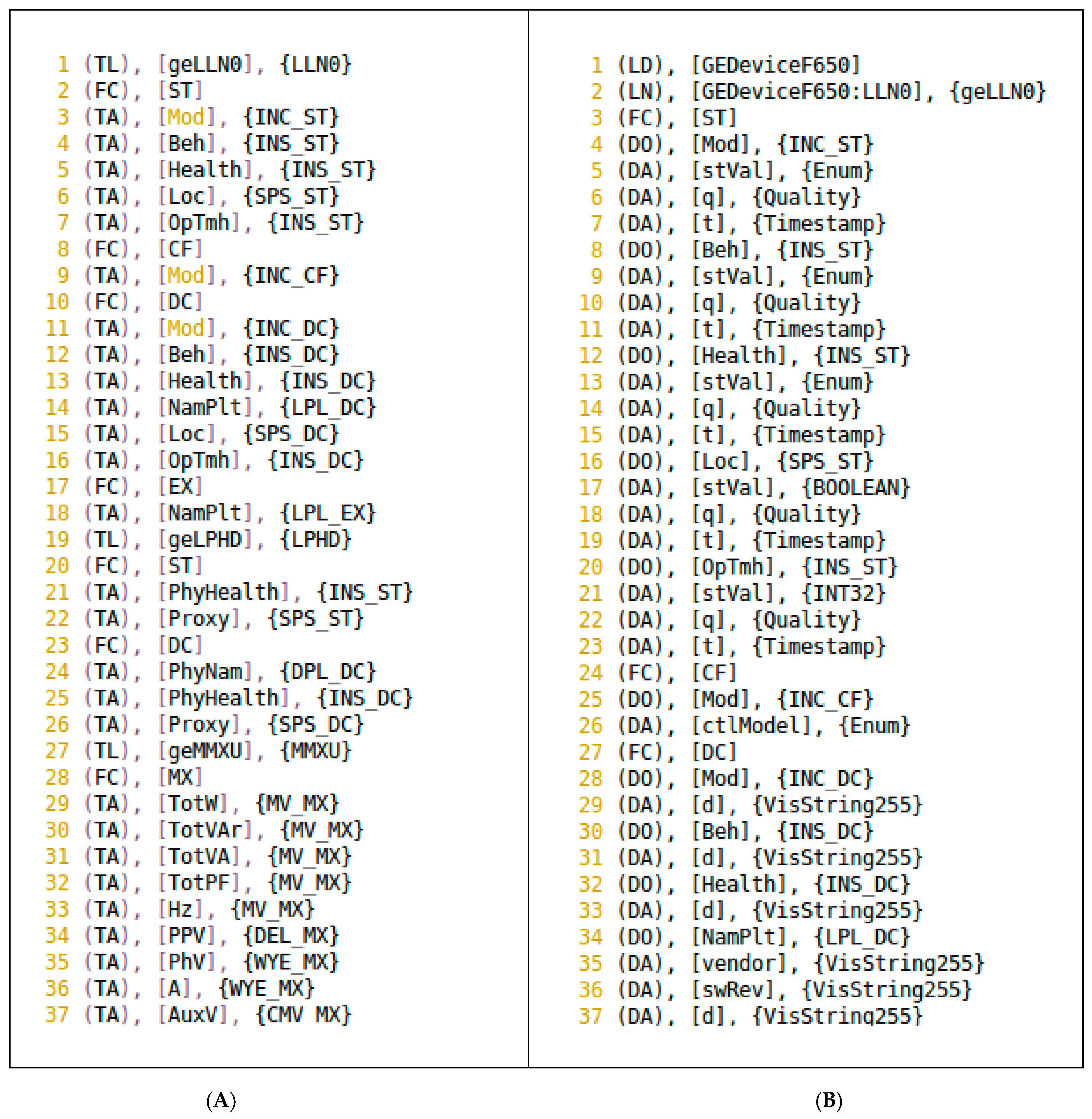
Table 4 shows an example of mapping using the IEC 61850 information model defined in IEC 61850-7-4. The logical node is to be composed of several CDCs. The logical node is composed of three categories of data, and status information can be information that controls the logical node. The categories are defined in several classes of data. The logical node is mapped to the OPC UA node model based on the previously mapped CDC.
The UaModeler tool is used to implement the OPC UA AddressSpace for IEC 61850 ACSI mapping. The UaModeler tool produces the source code for types of mapped IEC 61850 models (e.g., XCBR type). It can easily implement information modeling, and it is represented graphically for the OPC UA AddressSpace. The generated source code is C++, ANSI C, .NET [17].

2.4. SCL to OPC UA AddressSpace Module Implementation

The IEC 61850 server uses SCL files and preferences for the server. The OPC UA AddressSpace may configure the IEC 61850 model information using SCL files, because the IEC 61850 server configures the information model using SCL files. The SCL to OPC UA AddressSpace module converts the IEC 61850 model information in the SCL file into OPC UA AddressSpace information. The mapping types in Section 2.3 help the conversion. The OPC UA AddressSpace creation process is performed in two steps.
Figure 9 shows step 1. Step 1 creates the TDF (type definition file) and NDF (node definition file) with the Data Map Tool. The Data Map Tool maps the IEC 61850 model information—logical device, logical node, functional constraint, data object, and data attribute. TDF is type definition file for IEC 61850 node in SCL file. NDF is node definition file for IEC 61850 node in SCL file. TDF and NDF make SCL information simple; they help to create logical node instances for a predefined logical node type in OPC UA. With TDF and NDF, the mapping process time is reduced to less than one minute. The TDF and NDF are shown in Figure 10.
Figure 11 shows step 2. The SCL to OPC UA AddressSpace module generates the OPC UA source code for building the OPC UA server using the TDF and the NDF. The generated OPC UA source code is configured as the OPC UA AddressSpace of the OPC UA server for the IED represented in the IEC 61850 model. The code for the types of mapped IEC 61850 model was created in Section 2.3. Thus, generated code is valid for IEDs or any IEC 61850 systems due it is able to receive as input and SCL file.

3. Experimental Results and Performance Evaluation

The OPC UA server contains the OPC UA server module and IEC 61850 client input/output (I/O) module. The OPC UA server module configures the OPC UA AddressSpace for the IEC 61850 model. The OPC UA client can access the IEC 61850 information model by searching for a node in the OPC UA AddressSpace. If the OPC UA server synchronizes with the data of the actual IEC 61850 server, the OPC UA client may be used to obtain the data in the IEC 61850 server without using the IEC 61850 protocol.
Figure 12 shows a network diagram between IEC 61850 and OPC UA. The OPC UA client requests the service for the OPC UA server. The OPC UA server module is transmitted to the IEC 61850 client I/O modules via the interprocess communication (IPC) service required. The IEC 61850 client I/O modules deliver the required service to the IEC 61850 server. Table 5 shows test environments.
We have performed an IEC 61850 and OPC UA interlock test using SCL files with the IED information of the four manufacturers—Table 6; these are the SCL files that compose the real IED. All four SCL files were successfully converted to the OPC UA AddressSpace.
Figure 13 shows the results of IEC 61850–OPC UA interconnection. Figure 13b is the IEC 61850 model information using KEMA’s UniCA IED simulator [19]. Figure 13a shows that UA’s Expert tool (OPC UA client) accesses the IEC 61850 model information by searching for nodes in the OPC UA AddressSpace [5]. The results of the IEC 61850–OPC UA interconnection include logical device, logical node, functional constraint, data object, and data attribute. GEDeviceF650 is a Logical Device for the generator role. GGIOs (generic process input/output) are logical nodes. This node is used only to model process devices that are not predefined by LN groups in a generic way. CF (configuration), DC (description), EX (extended definition), MX (measurands), and ST (status) are the functional constraints. AnIn is a data object with the CDC MV (measured values) type. The data attributes (db, RangeC, units) belong to MV CF.
We have performed simulations in an environment as shown in Figure 12. We simulated throughput for the IEC 61850 and OPC UA network area, and the results are shown in Figure 14. We used GetDataValues service. The throughput of IEC 61850 is 65,000 byte/s, and the throughput of OPC UA is 20,000 byte/s. The OPC UA network’s throughput is lower than that of the IEC 61850 network, and this result means that the number of messages of IEC 61850 is greater than that of OPC UA. The OPC UA can efficiently transmit a greater number of items.
Figure 15 and Figure 16 show the round-trip time (RTT) of IEC 61850 (IEC 61850 client module—KEMA IED Simulator) and OPC UA (UA Expert—OPC UA server module). We used GetDataValues service. The RTT of IEC 61850 is less than 8 ms. On the other hand, the RTT of OPC UA is less than 20 ms, thus the RTT of OPC UA is higher than IEC 61850. (1) The OPC UA server module conveys the information received from the IEC 61850 client module to the OPC UA Client; (2) The OPC UA server module performs a process for mapping the IEC 61850 data model and OPC UA AddressSpace model. All information about mapping data was exchanged correctly.
Figure 17 and Figure 18 are Wireshark IO graphs of IEC 61850 GOOSE message (IEC 61850 client module—KEMA IED Simulator) and OPC UA (UA Expert—OPC UA server Module), respectively. We used GOOSE control block service. The IO graph of GOOSE is 120–160 packets/s. On the other hand, the IO graph of OPC UA is 43–46 packets/s, thus the IO graph of GOOSE is higher than OPC UA. (1) GOOSE messages support real-time communications for critical messages; (2) All devices sending GOOSE messages shall continue to send the message with a long cycle time, even if no status/value change has occurred.

4. Conclusions

With the development of technology, the smart grid has been certified as the underlying structure of the core strategy for energy saving. The power network requires a unified platform through the interworking of various power protocols. OPC UA adopted a unified platform because it provides a model for meta-information and an expandable type with an object-oriented model. The main aim of this paper has been to demonstrate how to convert the OPC UA information model through the analysis of the IEC 61850 standards and implement the SCL to OPC UA AddressSpace module using IEC 61850 SCL files. The SCL to OPC UA AddressSpace module can convert all SCL files. This paper has shown a process in which the SCL file (IEC61805 model) is converted to the OPC UA address of the OPC UA server. We were able to view and change the value of IEC 61850 data information in the OPC UA client using the technique proposed in this paper. All information about mapping data was exchanged correctly. The application of the OPC UA offers great potential in the smart grid field. This paper contributes to the identification of information and communication technologies (ICTs) capable of satisfying the communication requirements for future power systems.

Acknowledgments

This research was supported by the Energy Technology Development Project through the Korea Institute of Energy Technology Evaluation and Planning (KETEP) funded by the Ministry of Trade, Industry & Energy (MOTIE) (No.: 20131020400660 and No.: 20131020402080) and Seokyeong University (2016).

Author Contributions

In-Jae Shin and Byung-Kwen Song designed the study and the simulation. In-Jae Shin performed the simulation and data analysis. In-Jae Shin wrote the paper, with assistance and editing from Byung-Kwen Song, Doo-Seop Eom.

Conflicts of Interest

The authors declare no conflict of interest.

References

  1. Lehnhoff, S.; Rohjans, S.; Uslar, M.; Mahnke, W. OPC UA Unified Architecture: A Service-Oriented Architecture for Smart Grids. In Proceedings of the First International Workshop on Software Engineering Challenges for the Smart Grid, Zurich, Switzerland, 2–9 June 2012.
  2. Lehnhoff, S.; Mahnke, W.; Rohjans, S.; Uslar, M. IEC 61850 based OPC UA Communication—The Future of Smart Grid Automation. In Proceedings of the 17th Power Systems Computation Conference (PSCC’11), Stockholm, Sweden, 22–26 August 2011.
  3. International Electrotechnical Commission. Part 1: Overview and Concepts. In IEC 62541-1: OPC Unified Architecture, 1st ed.; Springer: Berlin/Heidelberg, Germany, 2008. [Google Scholar]
  4. Naumann, A.; Bielchev, I.; Voropai, N.; Styczynski, Z. Smart grid automation using IEC 61850 and CIM standards. Control Eng. Pract. 2014, 25, 102–111. [Google Scholar] [CrossRef]
  5. Buchholz, B.M.; Brunner, C.; Naumann, A.; Styczynski, Z. Applying IEC standards for communication and data management as the backbone of smart distribution. In Proceedings of the 2012 IEEE Power and Energy Society General Meeting (PES 2012), San Diego, CA, USA, 22–26 July 2012.
  6. Cavalieri, S.; Regalbuto, A. Integration of IEC 61850 SCL and OPC UA to improve interoperability in Smart Grid environment. Comput. Stand. Interfaces 2016, 47, 77–99. [Google Scholar] [CrossRef]
  7. Srinivasan, S.; Kumar, R.; Vain, J. Integration of IEC 61850 and OPC UA for Smart Grid automation. In Proceedings of the 2013 IEEE Innovative Smart Grid Technologies-Asia (ISGT Asia), Bangalore, India, 10–13 November 2013.
  8. Cintuglu, M.H.; Martin, H.; Mohammed, O.A. An intelligent multi agent framework for active distribution networks based on IEC 61850 and FIPA standards. In Proceedings of the 2015 18th International Conference on Intelligent System Application to Power Systems (ISAP), Porto, Portugal, 11–16 September 2015.
  9. Mahnke, W.; Leitner, S.-H.; Damm, M. OPC Unified Architecture; Springer: Berlin/Heidelberg, Germany, 2009. [Google Scholar]
  10. International Electrotechnical Commission. Part 3: Address Space Model. In IEC 62541-3: OPC Unified Architecture, 1st ed.; Springer: Berlin/Heidelberg, Germany, 2008. [Google Scholar]
  11. International Electrotechnical Commission. Part 7-1: Basic Communication Structure—Principles and Models. In International Standard IEC 61850, Communication Networks and Systems for Power Utility Automation, 2nd ed.; IEC: Geneva, Switzerland, 2010. [Google Scholar]
  12. International Electrotechnical Commission. Part 7-2: Basic Information and Communication Structure Abstract Communication Service Interface (ACSI). In International Standard IEC 61850, Communication Networks and SYSTEMS for Power Utility Automation, 2nd ed.; IEC: Geneva, Switzerland, 2010. [Google Scholar]
  13. International Electrotechnical Commission. Part 7-3: Basic Communication Structure for Substation and Feeder Equipment Common Data Classes. In International Standard IEC 61850, Communication Networks and Systems for Power Utility Automation, 2nd ed.; IEC: Geneva, Switzerland, 2010. [Google Scholar]
  14. International Electrotechnical Commission. Part 8-1: Specific Communication Service Mapping (SCSM)—Mappings to MMS (ISO 9506-1 and ISO 9506-2) and to ISO/IEC 8802-3. In International Standard IEC 61850, Communication Networks and Systems for Power Utility Automation, 2nd ed.; IEC: Geneva, Switzerland, 2011. [Google Scholar]
  15. International Electrotechnical Commission. Part 6: Configuration Description Language for Communication in Electrical Substations. In International Standard IEC 61850, Communication Networks and Systems for Power Utility Automation, 2nd ed.; IEC: Geneva, Switzerland, 2009. [Google Scholar]
  16. International Electrotechnical Commission. Part 7-4: Basic communication structure—Compatible Logical Node Classes and Data Object Classes. In International Standard IEC 61850, Communication Networks and Systems for Power Utility Automation, 2nd ed.; IEC: Geneva, Switzerland, 2010. [Google Scholar]
  17. Unified Automation, UA Server SDK C++ Bundle 1.3.1. Available online: www.unified-automation.com (accessed on 24 June 2016).
  18. SISCO Inc. MMS-EASE Lite 5.02; SISCO Inc.: Rancho Dominguez, CA, USA, 2008. [Google Scholar]
  19. DNV KEMA Energy & Sustainability, UniCA IED Simulator User Manual; DNV KEMA: Groningen, The Netherlands, 2012.
  20. Unified Automation, UA Modeler. Available online: www.unified-automation.com (accessed on 24 June 2016).
Figure 1. Information model of integrated OLE (object linking and embedding) for process control OPC unified architecture (UA).
Energies 09 00901 g001
Figure 2. OPC UA address space.
Energies 09 00901 g002
Figure 3. OPC UA AddressSpace.
Energies 09 00901 g003
Figure 4. IEC 61850 information model (Source: IEC 61850-7-2).
Energies 09 00901 g004
Figure 5. The whole design flow.
Energies 09 00901 g005
Figure 6. Mapping of the IEC 61850 information model onto OPC UA AddressSpace.
Energies 09 00901 g006
Figure 7. Abstract Communication Service Interface (ACSI) server class mapping.
Energies 09 00901 g007
Figure 8. ACSI logical device mapping.
Energies 09 00901 g008
Figure 9. Step 1: Creation of TDF (type definition file) and NDF (node definition file).
Energies 09 00901 g009
Figure 10. Examples of TDF and NDF. (A) Example of a created TDF file. Parentheses indicate the data type—(TL) is the type of logical node, (FC) is the functional constraint, and (TA) is a type of data attribute. Brackets indicate the name of the data and the data for each data type and braces indicate the name of the type; (B) Example of a created NDF file. Parentheses indicate the data type—(LD) is an instance of a logical device, (LN) is an instance of a logical node, (FC) is the functional constraint, (DO) is the data object, and (DA) is the data attribute. Brackets indicate the name of the data and the data for each data type and braces indicate the name of the type.
Energies 09 00901 g010
Figure 11. Step 2: Generation of OPC UA source code.
Energies 09 00901 g011
Figure 12. Network diagram between IEC 61850 and OPC UA.
Energies 09 00901 g012
Figure 13. Results of IEC 61850–OPC UA interconnection. (a) UA’s Expert tool (OPC UA client); (b) KEMA’s UniCA IED (intelligent electronic device) Simulator (IEC 61850 server).
Energies 09 00901 g013
Figure 14. OPC UA and IEC 61850 throughput.
Energies 09 00901 g014
Figure 15. Round-trip time (IEC 61850: IEC 61850 client module—KEMA IED Simulator).
Energies 09 00901 g015
Figure 16. Round-trip time (OPC UA: UA Expert—OPC UA server module).
Energies 09 00901 g016
Figure 17. Wireshark IO (input/output) graphs: packet (IEC 61850 Client module—KEMA IED Simulator).
Energies 09 00901 g017
Figure 18. Wireshark IO graphs: OPC UA packet (UA Expert—OPC UA server module).
Energies 09 00901 g018
Table 1. IEC 61850 logical node (LN) groups [16].
Logical Node GroupsNumber of Logical Nodes
System logical nodes3
Protection functions28
Protection related functions10
Supervisory control5
Generic references3
Interfacing and archiving4
Automatic control4
Metering and measurement8
Sensors and monitoring4
Switchgear2
Instrument transformer2
Power transformer4
Further power system equipment15
Total number of logical nodes92
Table 2. Data-type mapping.
IEC 61850 BasicTypesOPC UA BaseDataType
BOOLEANBoolean
INT8Number-Integer-Sbyte
INT16Number-Integer-Int16
INT24Number-Integer-Int32
INT32Number-Integer-Int32
INT128Number-Integer-Int64
INT8UNumber-Integer-Uinteger-Byte
INT16UNumber-Integer-Uinteger-UInt16
INT24UNumber-Integer-Uinteger-UInt32
INT32UNumber-Integer-Uinteger-UInt32
FLOAT32Number-Float
FLOAT64Number-Double
ENUMERATEDEnumeration
CODED ENUMEnumeration
OCTET STRINGByteString
VISIBLE STRINGString
UNICODE STRINGString
Table 3. Example of common data class: DPS (double point status) mapping.
PDS Type
NameType DefinitionData TypeNode Class Type
Data Name
Data Attribute
Status
stValEnum_stValEnumerationVariable
qQuality_typeBaseDataTypeVariable
tTimeStamp_typeBaseDataTypeVariable
Substitution
subEnaDataAttribute_TypeBooleanVariable
subValDnum_stValEnumerationVariable
subQQuality_typeBaseDataTypeVariable
subIDDataAttribute_TypeStringVariable
Configuration, description and extension
dDataAttribute_TypeStringVariable
dUDataAttribute_TypeStringVariable
cdcNsDataAttribute_TypeStringVariable
cdcNameDataAttribute_TypeStringVariable
dataNsDataAttribute_TypeStringVariable
Table 4. Example of logical node: XCBR mapping.
XCBR Type
NameType DefinitionModeling RuleData TypeNode Class
LLNameObjectName_TypeMandatoryBaseDataTypeVariable
Data
Data from Common_LN_TypeOverride Instance DeclarationMandatory Object
LocSPS_TypeMandatory Object
EEHealthINS_TypeOptional Object
EENameDPL_TypeOptional Object
OpCntINS_TypeMandatory Object
PosDPC_TypeMandatory Object
BlkOpnSPC_TypeMandatory Object
BlkClsSPC_TypeMandatory Object
ChamotEnaSPC_TypeOptional Object
SumSwARsBCR_TypeOptional Object
CBOpCapINS_TypeMandatory Object
POWCapINS_TypeOptional Object
MaxOpCapINS_TypeOptional Object
Table 5. Test environments [17,18,19,20].
ComponentOPC UA ClientOPC UA ServerIEC 61850 ClientIEC 61850 Server
OSUbuntu 14.04Ubuntu 14.04Ubuntu 14.04Windows
ToolUA’s UaExpert KEMA’s UniCA IED Simulator
SDK UA’s OPC UA SDK 1.3.1Sisco’s MMS-EASE Lite 5.02
Language C++C
Table 6. The number of nodes for each data type and rate of conversion.
MetricIED AIED BIED CIED D
Logical Device(Num)2414
Logical Node(Num)8021781116
Data Object(Num)9792532840809
Data Attribute(Num)2795627620952108
Conversion (%)100%100%100%100%

