
Cooperative Energy Management of Hybrid DC Renewable Grid Using Decentralized Control Strategies


Abstract
:1. Introduction
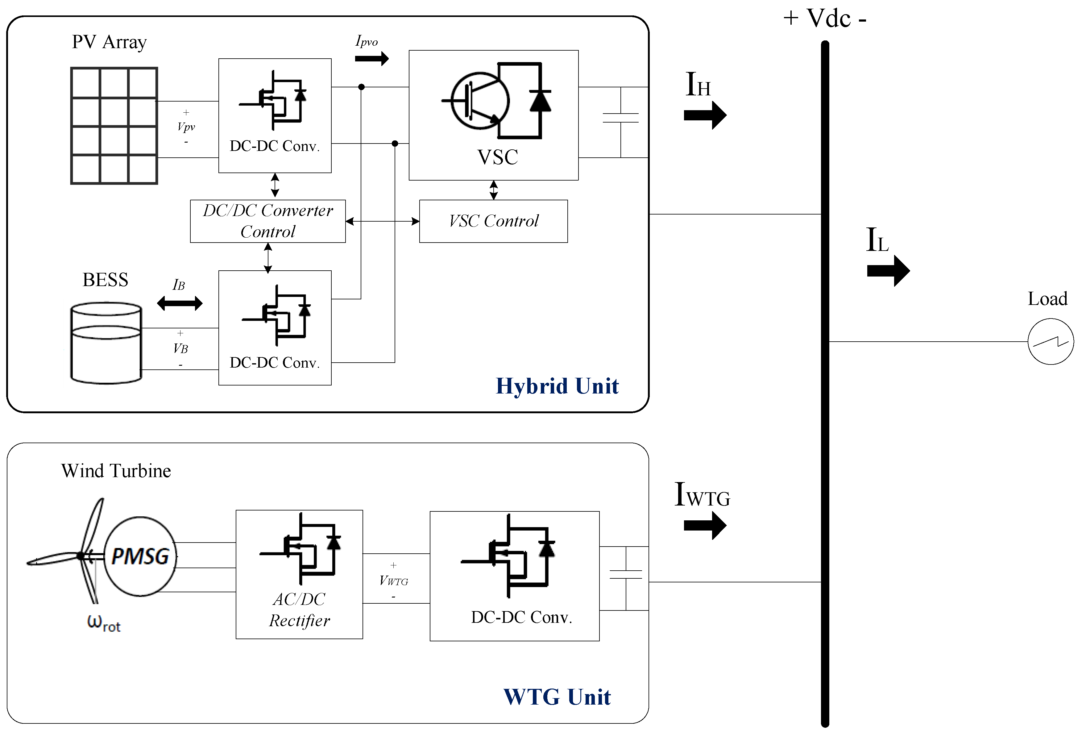
2. Hybrid Structure of DC Microgrid
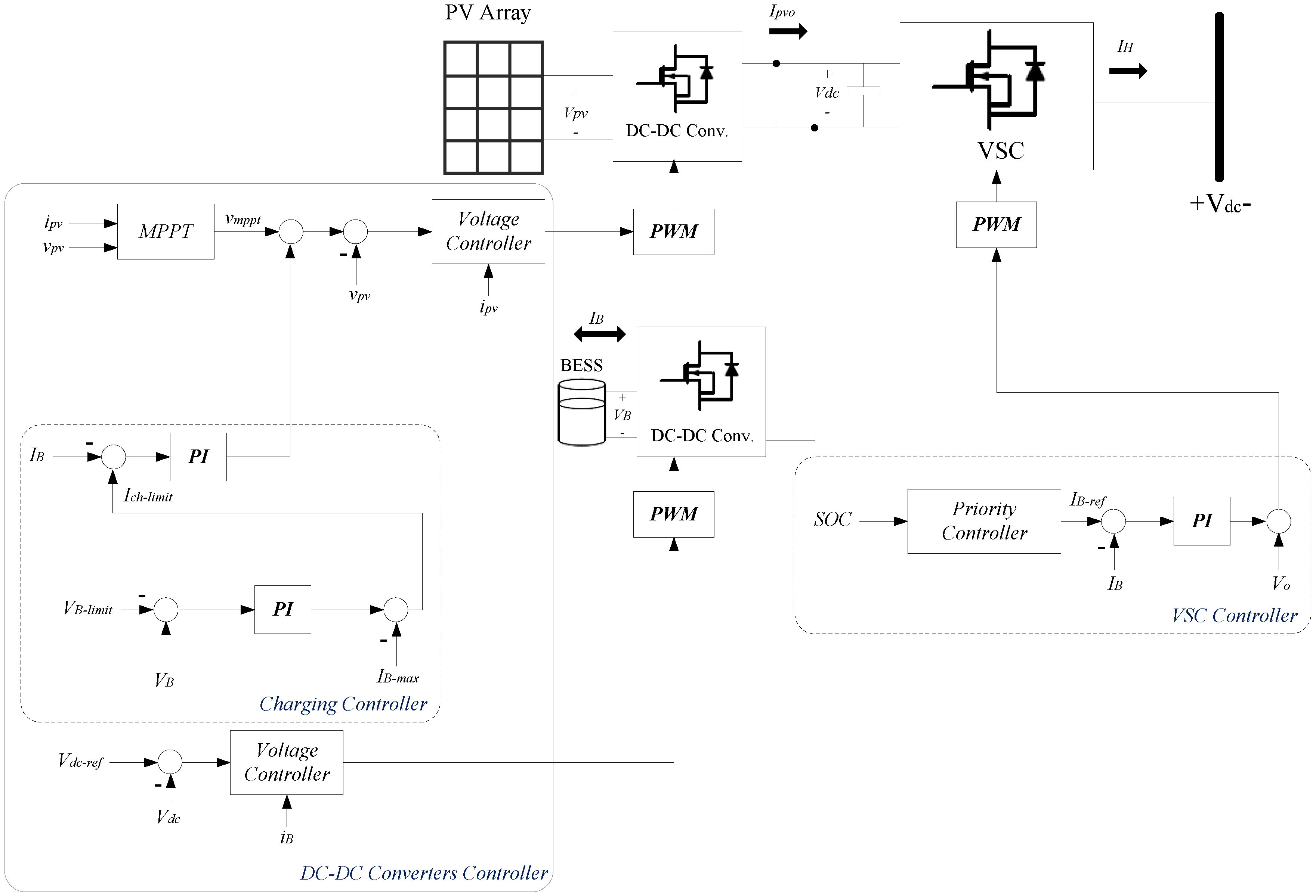
3. Proposed Control Strategy
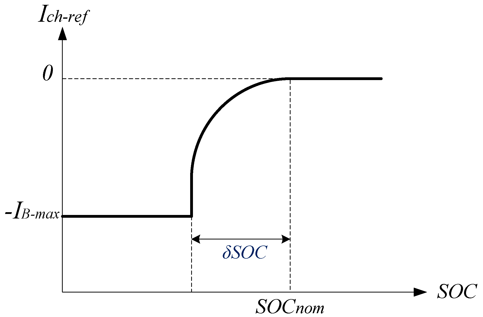
- Level 1: At this level, priority of control strategy has been set based on the battery charge or delivery of total power available in PV to the microgrid. In fact, Priority Controller will determine the target based on the battery SOC level.
- Level 2: Control objectives in this level have been set based on supporting power balance in DC microgrid and preventing the battery SOC from exceeding the allowable range.
3.1. Nominal Operation Scenario
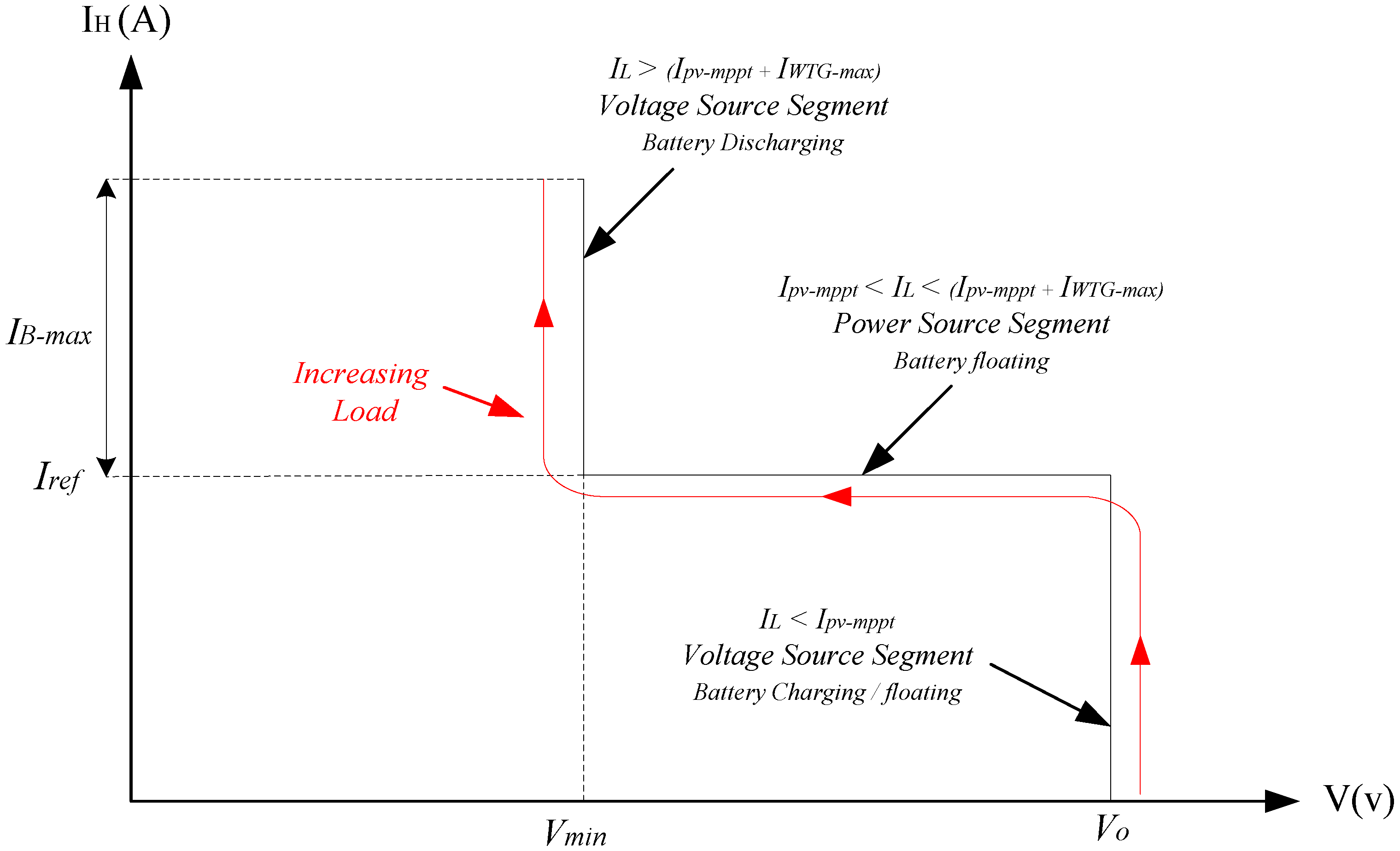
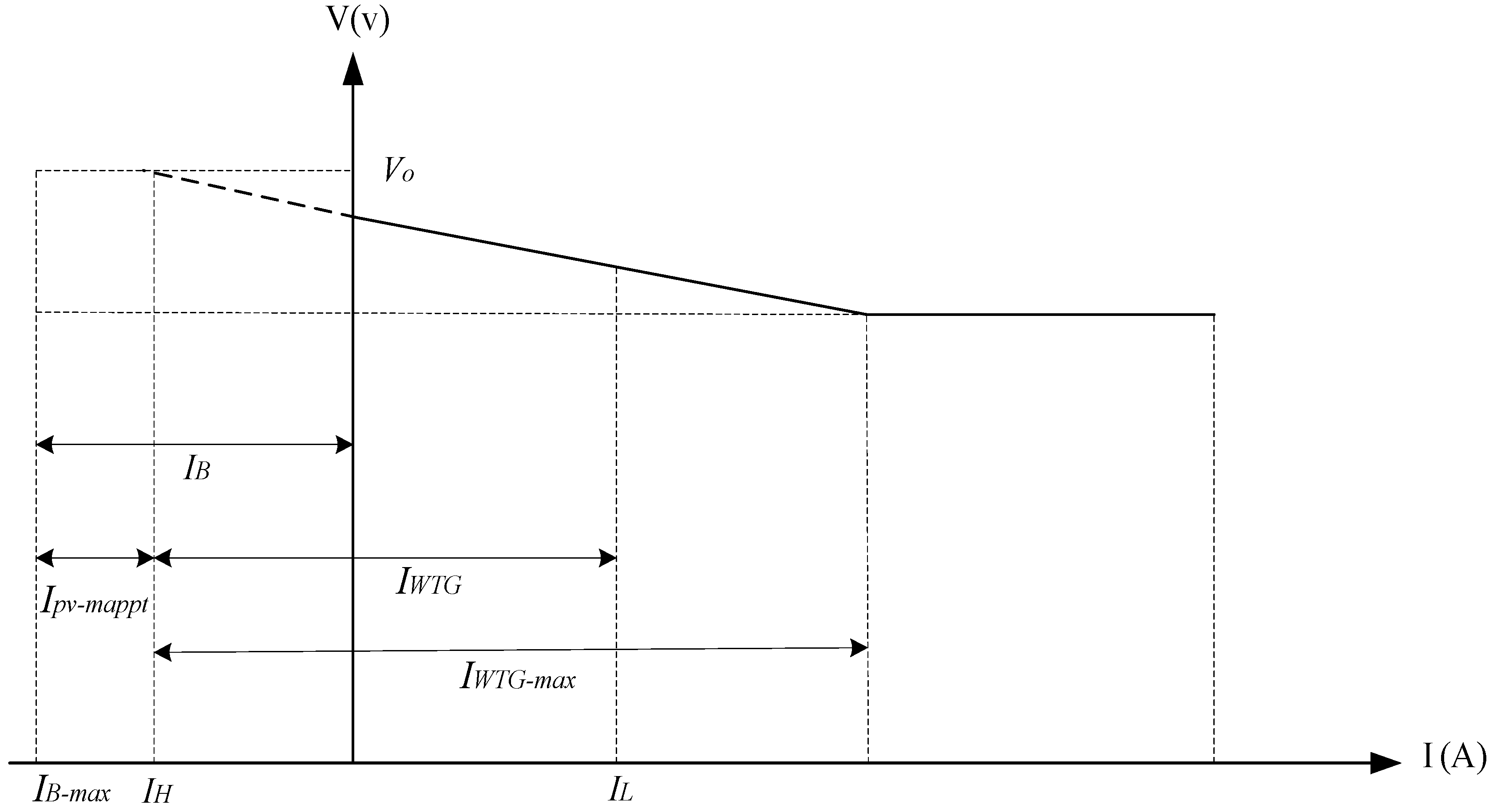
- This control strategy becomes operational when . In this case, Priority Controller zeros the IB-ref reference current. Therefore, Iref current is determined on the basis of . It is noteworthy that Priority Controller has no direct or closed-loop control on the BESS, but the battery current is controlled rather indirectly by injecting current into the microgrid in reference value Iref. This design helps support the power balance in the microgrid and put the supply of load demand on the highest priority in operational scenarios. The system’s operating point can be placed on any part of I/V characteristic of microgrid based on the load demand and Ipv-mppt, which are divided into three subcategories:
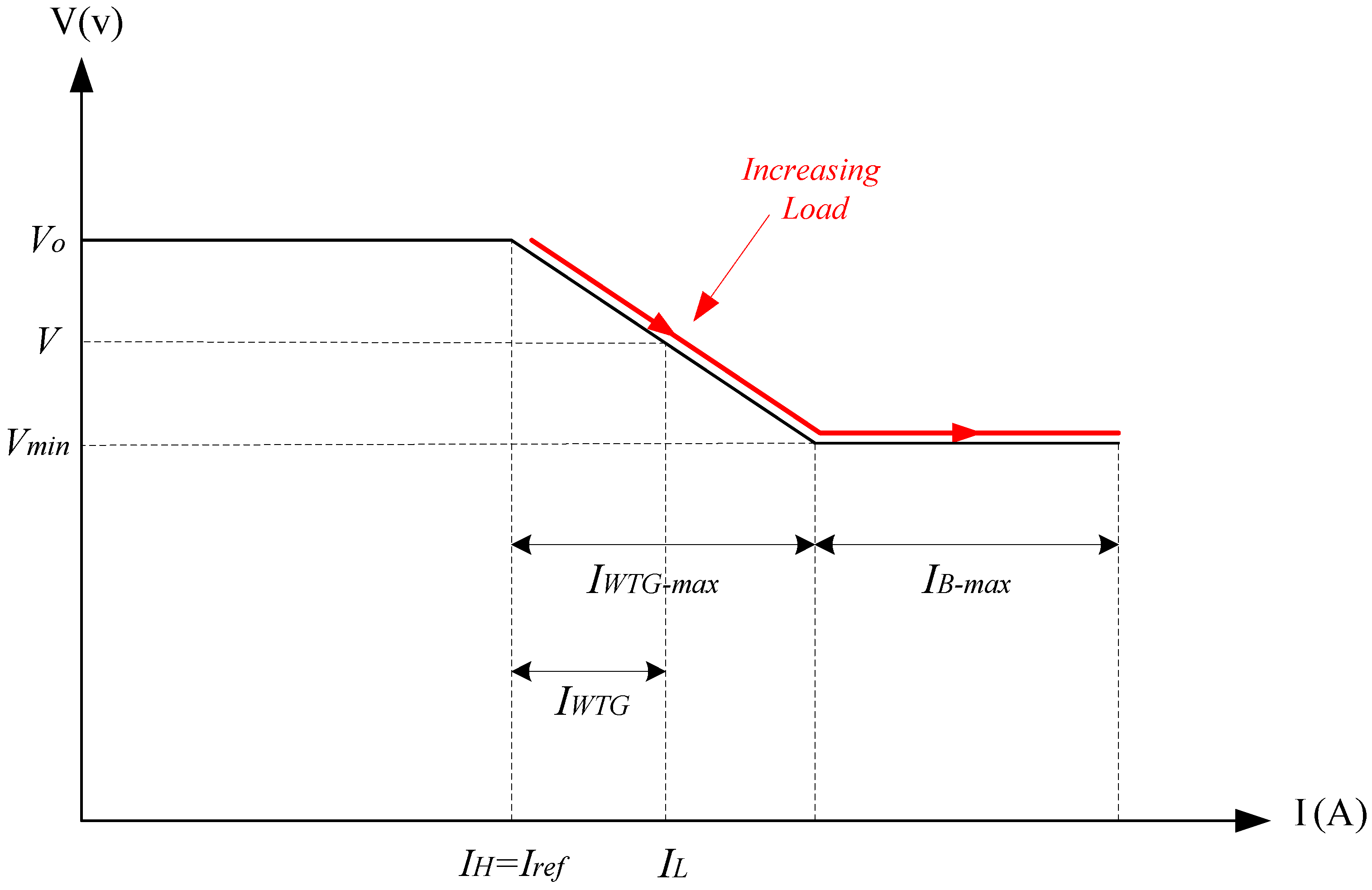
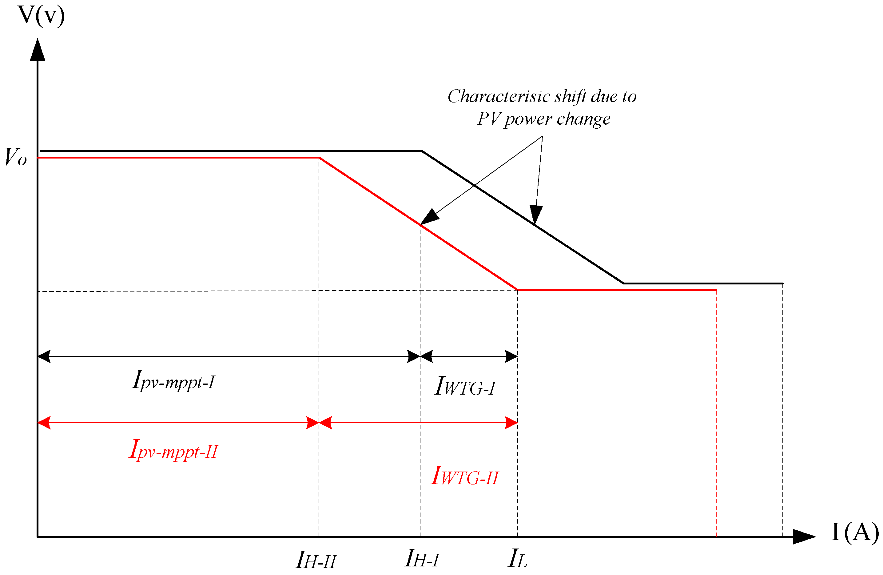
- : This mode is equivalent to the middle part of characteristics in Figure 4 and Figure 5, where the hybrid unit injects the total power available in PV unit into the microgrid. The rest of the load demand is supplied by the WTG, maintaining and regulating the microgrid voltage within the allowable range based on the droop characteristic of WTG. Notably, IPv-mppt varied depending on the level of solar radiation and temperature. Hence, any decrease or increase in power generation of PV unit will move I/V characteristic to the left or right in Figure 5, respectively. This effect is shown in Figure 6 where the power output of PV module has decreased from point I to II, which caused power losses of hybrid module from IH-I to IH-II, transferring the entire I/V curve to the left. Moreover, the power output of WTG increases from point I to II in order to compensate the shortage power generation of PV module.
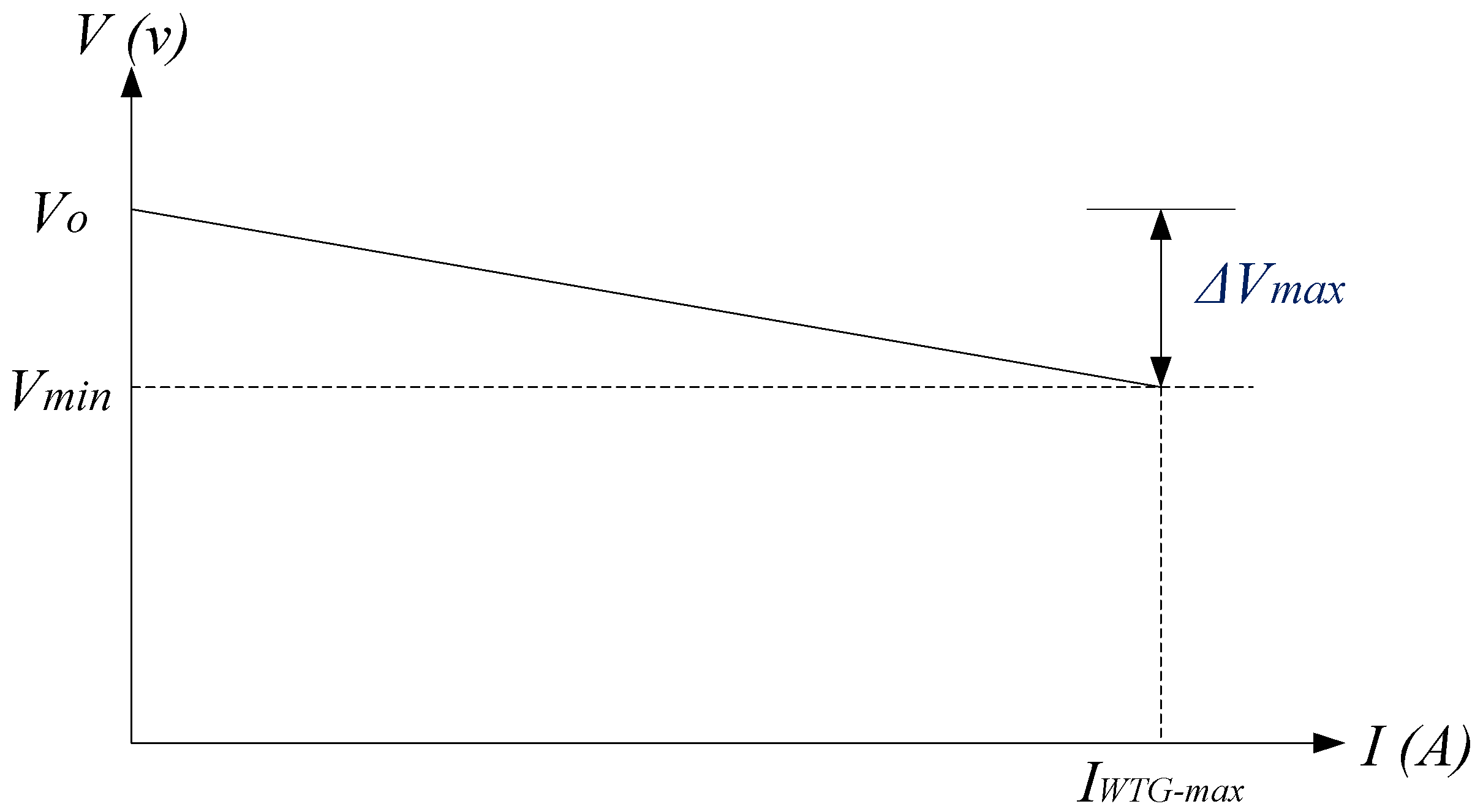
- : The WTG decreases the voltage in response to the increased load demand based on the droop characteristic, achieving its nominal current at point . If the load increases once again or the PV module generation power decreases, since the load demand (IL) is greater than the total generation of DGs, WTG will attempt to bring the voltage to less than Vmin. Therefore, the hybrid unit begins to adjust the DC bus voltage in Vmin value based on I/V curve suggested in Figure 5. This target is achieved by regulating the output of WTG within its nominal range and supplying the power shortage by the hybrid unit so as to establish a power balance in the microgrid. In fact, the DC-DC converter of BESS injects the excess current in order to adjust the microgrid voltage within the allowable range. Notably, in this scenario, if the load current exceeds the nominal current of the battery and the battery is fully discharged, the load shedding scenario should be implemented, but it is beyond the scope of this paper.
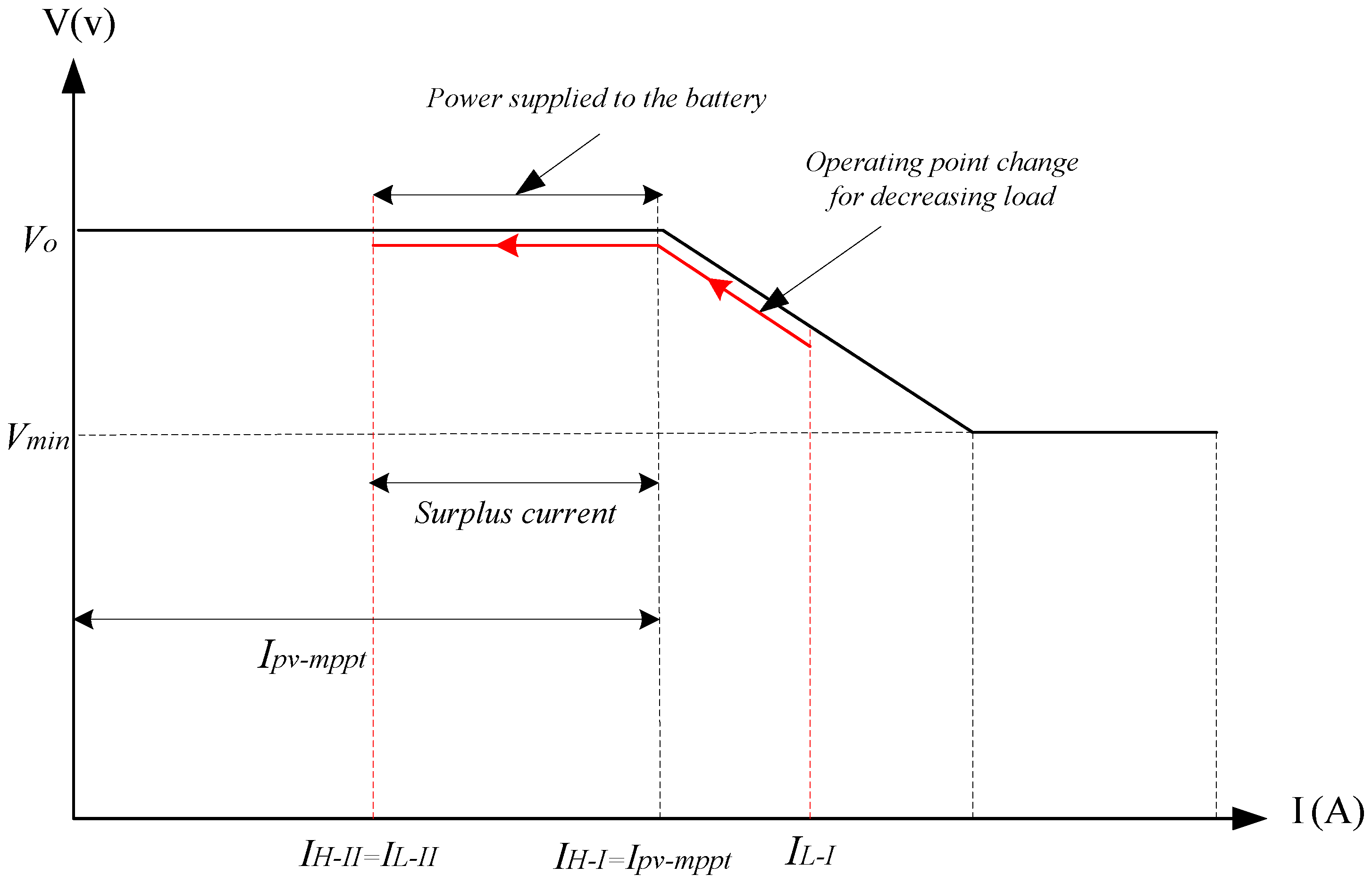
- : In this mode, since the hybrid unit inclines at any moment to inject current Ipv-mppt into the microgrid and this current is more than the load demand, the current generated by WTG becomes zero, supplying the total load demand by the hybrid unit in . Moreover, since the range of Ipv-mppt produced by the hybrid unit is more than the load demand, the microgrid voltage tends to rise to more than nominal value Vo. In this situation, the DC/DC converter absorbs the excess current () and charge the battery (if necessary) to regulate the DC link voltage within the allowable range or the MPPT controller of PV unit transfers the operating point out to the MPP region, thus adapting the generation power to the load demand. This mechanism can maintain the power balance in the hybrid unit and microgrid. This scenario is shown in Figure 7 where the load demand drops from IL-I to IL-II. Notably, although the target in this mode is to inject the total power of PV module into the microgrid, the top priority is to establish the power balance in the microgrid. This can be fulfilled by supplying the load demand and storing the excess energy if necessary.
3.2. BESS Charging Scenario
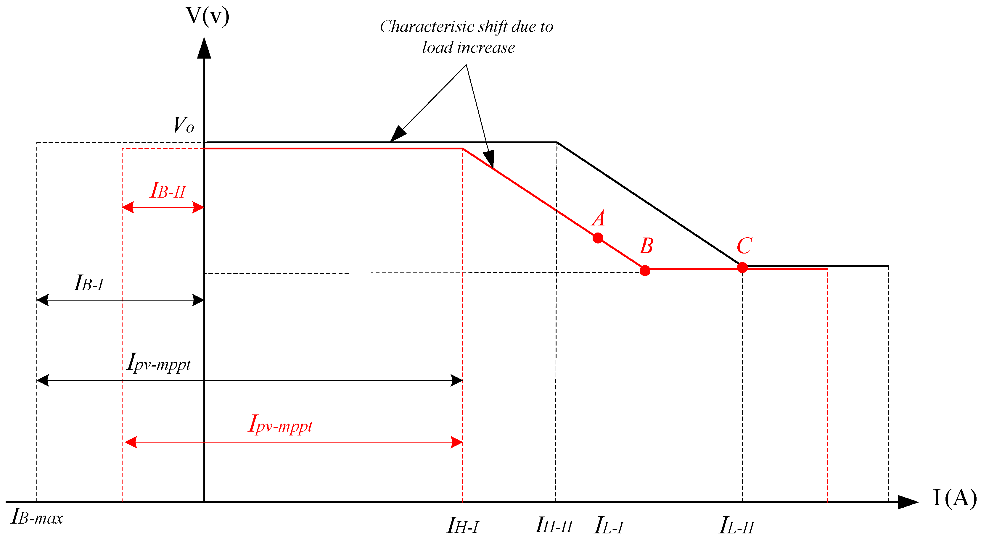
- : In this case, the current produced by PV unit is sufficient for battery charge and excessive current is injected into the microgrid. Current injection into the microgrid (IH) is derived from the difference (). In fact, when the VSC injects the current into the microgrid, the DC/DC converter of BESS injects the PV unit’s remaining power into the BESS in order to regulate the DC link voltage. Hence, the battery charging process can be fulfilled by indirectly controlling the power injected into the DC microgrid. It is noteworthy, however, the major target of control strategy in this scenario involves battery charge, and top priority is to support the establishment of power balance within the microgrid for decentralized controlling of the DC microgrid. Figure 9 illustrates the displacement of operating point and I/V characteristic in order to support the power balance during battery charging.As shown in the above figure, the battery is first charged separately by PV Unit with current as remaining current of PV supplies the load demand IL-I. The rest of the load demand will be supplied by WTG according to its droop characteristic (point A). WTG can supply any load rise until to the point B and Vmin. If the load demand increases beyond this point and to IL-II, the WTG will attempt to decrease the voltage based on the characteristic droop to below Vmin. Therefore, the hybrid unit in this scenario increases its output from IH-I to IH-II in order to stabilize and regulate the voltage range. Furthermore, the battery charge current decreases to IB-II in order to regulate the DC link voltage. The hybrid unit continues to supply the load demand until the maximum current injection (Ipv-mppt); therefore, the charge current becomes zero. Any increase in the load demand will be supplied by the BESS to support the power balance in the microgrid as described in Figure 5.
- : In this case, the reference current Iref is negative and the hybrid unit absorbs the current difference () so as to charge the battery in maximum current. This is equivalent to moving the I/V characteristic to the left according to Figure 10. In this situation, the hybrid unit acts as a load. The WTG will supply the battery charge current and any increase in the load demand up until its nominal current.
4. Coordination of Control System
5. Simulation Results
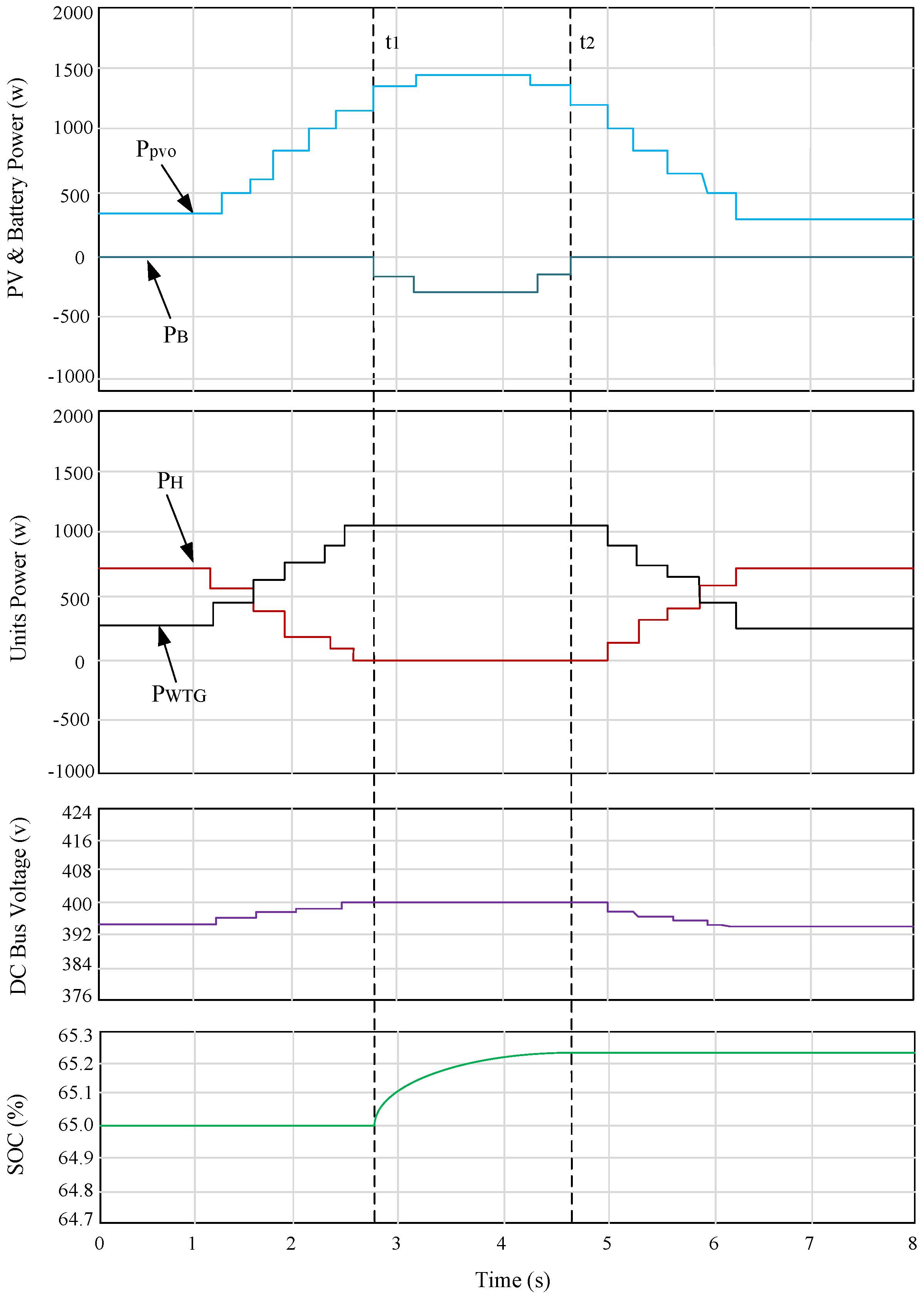
5.1. Nominal Scenario
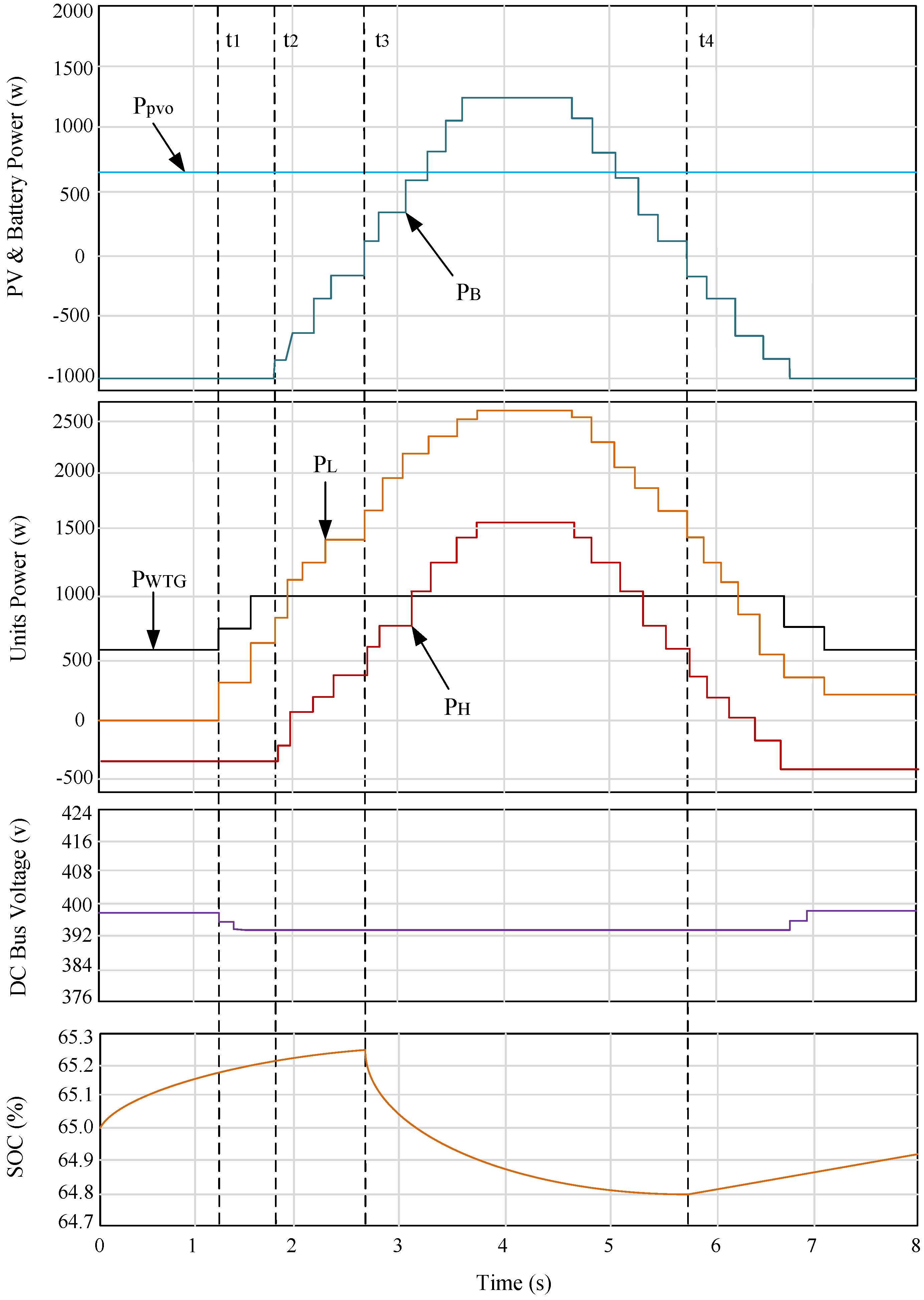
5.2. Charging Scenario
5.3. Transition between Operating Scenarios
6. Conclusions
Author Contributions
Conflicts of Interest
References
- Kahrobaeian, A.; Mohamed, Y.I. Network-based hybrid distributed power sharing and control for islanded microgrid systems. IEEE Trans. Power Electron. 2015, 30, 603–617. [Google Scholar] [CrossRef]
- Xiao, J.; Wang, P.; Setyawan, L. Multilevel energy management system for hybridization of energy storages in DC microgrids. IEEE Trans. Smart Grid. 2016, 7, 847–856. [Google Scholar] [CrossRef]
- Zeng, Z.; Yang, H.; Tang, S.; Zhao, R. Objective-oriented power quality compensation of multifunctional grid-tied inverters and its application in microgrids. IEEE Trans. Power Electron. 2015, 30, 1255–1265. [Google Scholar] [CrossRef]
- Du, W.; Jiang, Q.; Erikson, M.; Lasseter, R. Voltage-source control of PV inverter in a CERTS microgrid. IEEE Trans. Power Deliv. 2014, 29, 1726–1734. [Google Scholar] [CrossRef]
- Chen, D.; Xu, L.; Yao, L. DC voltage variation based autonomous control of DC microgrids. IEEE Trans. Power Deliv. 2013, 28, 637–648. [Google Scholar] [CrossRef]
- Olivares, D.; Canizares, C.; Kazerani, M. A centralized energy management system for isolated microgrids. IEEE Trans. Smart Grid 2014, 5, 1864–1875. [Google Scholar] [CrossRef]
- Anand, S.; Fernandes, B.G.; Guerrero, J. Distributed control to ensure proportional load sharing and improve voltage regulation in low-voltage DC microgrids. IEEE Trans. Power Electron. 2013, 28, 1900–1913. [Google Scholar] [CrossRef]
- Che, L.; Shahidehpour, M. DC microgrids: Economic operation and enhancement of resilience by hierarchical control. IEEE Trans. Smart Grid 2014, 5, 2517–2526. [Google Scholar]
- Tan, K.T.; Sivaneasan, B.; Peng, X.Y.; So, P.L. Control and operation of a DC grid-based wind power generation system in a microgrid. IEEE Trans. Energy Conversion. 2016, 31, 496–505. [Google Scholar] [CrossRef]
- Shafiee, Q.; Dragicevic, T.; Guerrero, J.V.J.M. Hierarchical control for multiple DC microgrids clusters. IEEE Trans. Energy Convers. 2014, 29, 922–933. [Google Scholar] [CrossRef]
- Jin, C.; Wang, P.; Xiao, J.; Tang, Y.; Choo, F.H. Implementation of hierarchical control in DC microgrids. IEEE Trans. Ind. Electron. 2014, 61, 4032–4042. [Google Scholar] [CrossRef]
- Eghtedarpour, N.; Farjah, E. Distributed charge/discharge control of energy storages in a renewable-energy-based DC microgrid. IET Renew. Power Gener. 2014, 8, 45–57. [Google Scholar] [CrossRef]
- Caldognetto, T.; Tenti, P. Microgrids operation based on master-slave cooperative control. IEEE J. Emerg. Sel. Top. Power Electron. 2014, 2, 1081–1088. [Google Scholar] [CrossRef]
- Majumder, R. A hybrid microgrid with DC connection at back to back converters. IEEE Trans. Smart Grid 2014, 5, 251–259. [Google Scholar] [CrossRef]
- Paquette, A.; Reno, M.; Harley, R.; Divan, D. Sharing transient loads: Causes of unequal transient load sharing in islanded microgrid operation. IEEE Ind. Appl. Mag. 2014, 20, 23–34. [Google Scholar] [CrossRef]
- Eghtedapour, N.; Farjah, E. Power control and management in a hybrid AC/DC microgrid. IEEE Trans. Smart Grid 2014, 5, 1494–1505. [Google Scholar] [CrossRef]
- Che, L.; Khodayar, M.; Shahidehpour, M. Only connect: Microgrids for distribution system restoration. IEEE Power Energy Mag. 2014, 12, 70–81. [Google Scholar]
- Lu, X.; Sun, K.; Guerrero, J.M.; Vasquez, J.C.; Huang, L. State of charge balance using adaptive droop control for distributed energy storage systems in DC micro-grid applications. IEEE Trans. Ind. Electron. 2014, 61, 2804–2815. [Google Scholar] [CrossRef]
- Augustine, S.; Mishra, M.K.; Lakshminarasamma, N. Adaptive droop control strategy for load sharing and circulating current minimization in low-voltage standalone DC microgrid. IEEE Trans. Sustain. Energy 2015, 6, 132–141. [Google Scholar] [CrossRef]
- Jiang, W.; Fahimi, B. Active current sharing and source management in fuel cell-battery hybrid power system. IEEE Trans. Ind. Electron. 2010, 57, 752–761. [Google Scholar] [CrossRef]
- Li, Y.W.; Kao, C.N. An accurate power control strategy for power electronic-interfaced distributed generation units operating in low-voltage multi-bus microgrid. IEEE Trans. Power Electron. 2009, 24, 2977–2988. [Google Scholar]
- Belvedere, B.; Bianchi, M.; Borghetti, A.; Nucci, C.A.; Paolone, M.; Peretto, A. A microcontroller-based power management system for a standalone microgrids with hybrid power supply. IEEE Trans. Sustain. Energy 2012, 3, 422–431. [Google Scholar] [CrossRef]
- Tan, K.T.; Peng, X.Y.; So, P.L.; Chu, Y.C.; Chen, M.Z.Q. Centralized control for parallel operation of distributed generation inverters in microgrids. IEEE Trans. Smart Grid 2012, 3, 1977–1987. [Google Scholar] [CrossRef]
- Wang, B.; Sechilariu, M.; Locment, F. Intelligent DC microgrid with smart grid communications: Control strategy consideration and control. IEEE Trans. Smart Grid 2012, 3, 2148–2156. [Google Scholar] [CrossRef]
- Tan, K.T.; So, P.L.; Chu, Y.C.; Chen, M.Z.Q. Coordinated control and energy management of distributed generation inverters in microgrid. IEEE Trans. Power Deliv. 2013, 28, 704–713. [Google Scholar] [CrossRef]
- Chen, Y.K.; Wu, Y.C.; Song, C.C.; Chen, Y.S. Design and implementation of energy management system with fuzzy control for DC microgrid systems. IEEE Trans. Power Electron. 2013, 28, 1563–1570. [Google Scholar] [CrossRef]
- Thounhomg, P.; Rael, S.; Davat, B. Control algorithm of fuel cell and batteries for distributed generation systems. IEEE Trans. Energy Convers. 2008, 23, 148–155. [Google Scholar]
- Koutroulis, E.; Kalaitzakis, K. Novel battery charging regulation system for photovoltaic applications. IEEE Proc. Electr. Power Appl. 2004, 151, 191–197. [Google Scholar] [CrossRef]
- Cao, Y.; Tang, S.; Li, C.; Zhang, P.; Tan, Y.; Zhang, Z.; Li, J. An optimized EV charging model considering Tou price and SOC curve. IEEE Trans. Smart Grid 2012, 3, 85–94. [Google Scholar] [CrossRef]
- Miao, Z.; Xu, L.; Disfani, V.R.; Fam, L. An SOC-based energy management system for microgrids. IEEE Trans. Smart Grid 2014, 5, 966–973. [Google Scholar] [CrossRef]
- Xu, L.; Chen, D. Control and operation of DC microgrid with variable generation and energy storage. IEEE Trans. Power Deliv. 2011, 26, 2513–2522. [Google Scholar] [CrossRef]
- Guerrero, J.M.; Vasquez, J.C.; Matas, J.; Castilla, M.; Vicuna, L.G.D. Hierarchical control of droop-controlled AC and DC microgrids—A general approach to standardization. IEEE Trans. Ind. Electron 2011, 58, 158–172. [Google Scholar] [CrossRef]
- Gu, Y.; Xiang, X.; Li, W.; He, X. Mode-adaptive decentralized control for renewable DC microgrid with enhanced reliability and flexibility. IEEE Trans. Power Electron. 2014, 29, 5072–5084. [Google Scholar] [CrossRef]


| Parameter | Symbol | Value |
|---|---|---|
| DC bus voltage Ref. | Vdc-ref | 400 V |
| Low threshold DC voltage | VL | 392 |
| High threshold DC voltage | VH | 408 |
| PV maximum Power | Ppv-mppt | 1500 W |
| WTG maximum power | PWTG-max | 1000 W |
| Battery capacity | Cbat | 32 Ah |
| BESS maximum power | PB-max | 1000 W |
| Initial SOC | SOC | 65% |
| Maximum SOC | SOCmax | 90% |
| Minimum SOC | SOCmin | 20% |
| Battery nominal voltage | VB | 156 V |
| Virtual resistance | Rd | 0.2 Ω |
| PV open circuit voltage | VOC | 287 V |
| PV short circuit current | ISC | 7.25 A |
| DC link capacitance | Cdc | 2400 µF |
© 2016 by the authors; licensee MDPI, Basel, Switzerland. This article is an open access article distributed under the terms and conditions of the Creative Commons Attribution (CC-BY) license (http://creativecommons.org/licenses/by/4.0/).
Share and Cite
Beykverdi, M.; Jalilvand, A.; Ehsan, M. Cooperative Energy Management of Hybrid DC Renewable Grid Using Decentralized Control Strategies. Energies 2016, 9, 859. https://doi.org/10.3390/en9110859
Beykverdi M, Jalilvand A, Ehsan M. Cooperative Energy Management of Hybrid DC Renewable Grid Using Decentralized Control Strategies. Energies. 2016; 9(11):859. https://doi.org/10.3390/en9110859
Chicago/Turabian StyleBeykverdi, Mehrdad, Abolfazl Jalilvand, and Mehdi Ehsan. 2016. "Cooperative Energy Management of Hybrid DC Renewable Grid Using Decentralized Control Strategies" Energies 9, no. 11: 859. https://doi.org/10.3390/en9110859
APA StyleBeykverdi, M., Jalilvand, A., & Ehsan, M. (2016). Cooperative Energy Management of Hybrid DC Renewable Grid Using Decentralized Control Strategies. Energies, 9(11), 859. https://doi.org/10.3390/en9110859