1. Introduction
With the shortage of fossil fuels, the soaring prices of international energy and the global greenhouse effect, countries have put forward higher requirements for the reduction of fuel consumptions and emissions. In order to solve these problems, many automobile researchers and manufacturers are developing the hybrid electric vehicle (HEV), which combines the engine and the motor as a power plant. Japan has launched many new types of HEVs after the Prius, such as Honda Corporation’s Vezel Hybrid, Mercedes-Benz’s S400 Hybrid and Ford’s Escape, Mercury Mariner series SUV, Ford C-MAX Energi and Fusion HEVs. Germany’s Audi also launched the Duo HEVs. Many other countries are also carrying out the research and production of HEVs.
There are many structures of HEVs. The one based on the compound-structure permanent-magnet (CSPM) motor has an electromagnetic power train system, which is one of the forefront techniques in HEV. In the traditional transmission system, we use the settled speed ratios to realize the dynamic performance and improve the efficiency of the HEV. The disadvantages of the fixed speed ratios are complexity of the structure, friction and mechanical loss; at the same time, the expenditure is too high. Compared with the traditional transmissions system, the electric variable transmission (EVT) has many virtues, which can integrate all of the features in one device, which will be more suitable for application in the HEV. The CSPM motor described in this paper can work as an EVT to realize the continuous change of the transmission ratio, composing a complete hybrid power system. It can serve as: (1) the transmission drive system of the HEV with the function of hybrid power, which simplifies the system structure greatly and realizes the internal combustion engine (ICE) idling stop, power compensation and braking energy regeneration and other purposes; (2) the converters of torque and speed, which can make the ICE always operate at the maximum efficiency district dependent on the working conditions. This will improve the fuel economy and reduce the emissions [
1,
2]. The theoretical analysis proves that under the suitable control strategies, the CSPM motor based on the electromagnetic energy conversion principle can completely replace the planetary gear in the Prius series HEV.
At present, domestic and foreign scholars mainly study the CSPM in following aspects, such as the structure design, mathematical modeling, magnetic coupling and magnetic system design, parameter matching, control strategy, mode switching, efficiency analysis, temperature rising and cooling system design and dual rotor brushless structure of the CSPM, and have developed different types of prototypes, laying the foundation for further research and practical application. The research mainly exists as follows [
3,
4,
5]: (1) study of the electromechanical coupling of HEVs based on the CSPM motor; according to the energy transfer mechanisms in different working modes, the CSPM motor can replace the continuously-variable transmission (CVT), starter, generator, clutch and other devices respectively, to achieve CVT mode, starter mode, generator mode, braking feedback mode, dynamic compensation mode and along with the ICE to drive vehicles; (2) research on control the strategy of HEVs based on the CSPM motor. The hybrid power transmission topology of HEVs based on the CSPM motor is changed; thus, the application of the traditional series and parallel HEVs control strategies is analyzed. The output of ICE and the energy storage device can be adjusted by controlling the stator motor (SM) and double rotor motor (DRM) of the CSPM motor, solving the problems, such as dynamic compensation, dynamic mode switching, dynamic control and speed sensor accuracy, etc. Due to the CSPM motor having a complicated structure, this leads to the transmission system being more complex and the control strategy difficult to formulate. Therefore, proposing an effective control strategy can improve the CSPM motors’ performances better.
On the outer rotor inside and outside surface of the CSPM motor is installed the permanent magnets, which reduce volume and improve the energy density of the motor.
However, the hybrid excitation source can easily lead to internal magnetic serious coupling, which causes a larger torque ripple, serious heating and is hard to control [
6]. There are two reasons for the magnetic coupling: one is the interaction between the magnetic fluxes of the two-layer permanent magnets and changing with the permanent magnets’ position; another is the coupling between the magnetic fluxes of the stator armature reaction and permanent magnets. Most of the magnetic fluxes flow along the outer rotor, so the fluxes produced by the two-layer permanent magnets have three relationships in the outer rotor: without interference, mutual overlaps and mutual offset, respectively. The saturation degree of the outer rotor is the lowest when the magnetic fluxes are mutually offset. This paper studies the magnetic coupling in the SM of the CSPM motor. Firstly, the parameter matching of the CSPM motor in the HEV is analyzed, and we receive the dynamic properties’ design parameters of the CSPM motor as the THS of the Prius. They both work as the series-parallel power split HEVs to satisfy the same load demand, but the HEV based on the CSPM motor is more compact, intelligent and noiseless. Then, the equivalent magnetic circuit model of the overall and the tangential and radial magnetic flux distribution in the CSPM motor’s outer rotor are established; then, we explore the internal magnetic coupling rule of the CSPM motor based on these two models. Finally, by using the finite element method (FEM) electromagnetic simulation to analyze the magnetic field of the CSPM motor in different working conditions, we propose an internal magnetic decoupling scheme, which meets the miniaturization, lightweight and control requirements, laying a foundation for the application of the CSPM motor in the HEV field.
2. Parameters Matching Analysis of the CSPM Motor in the HEV
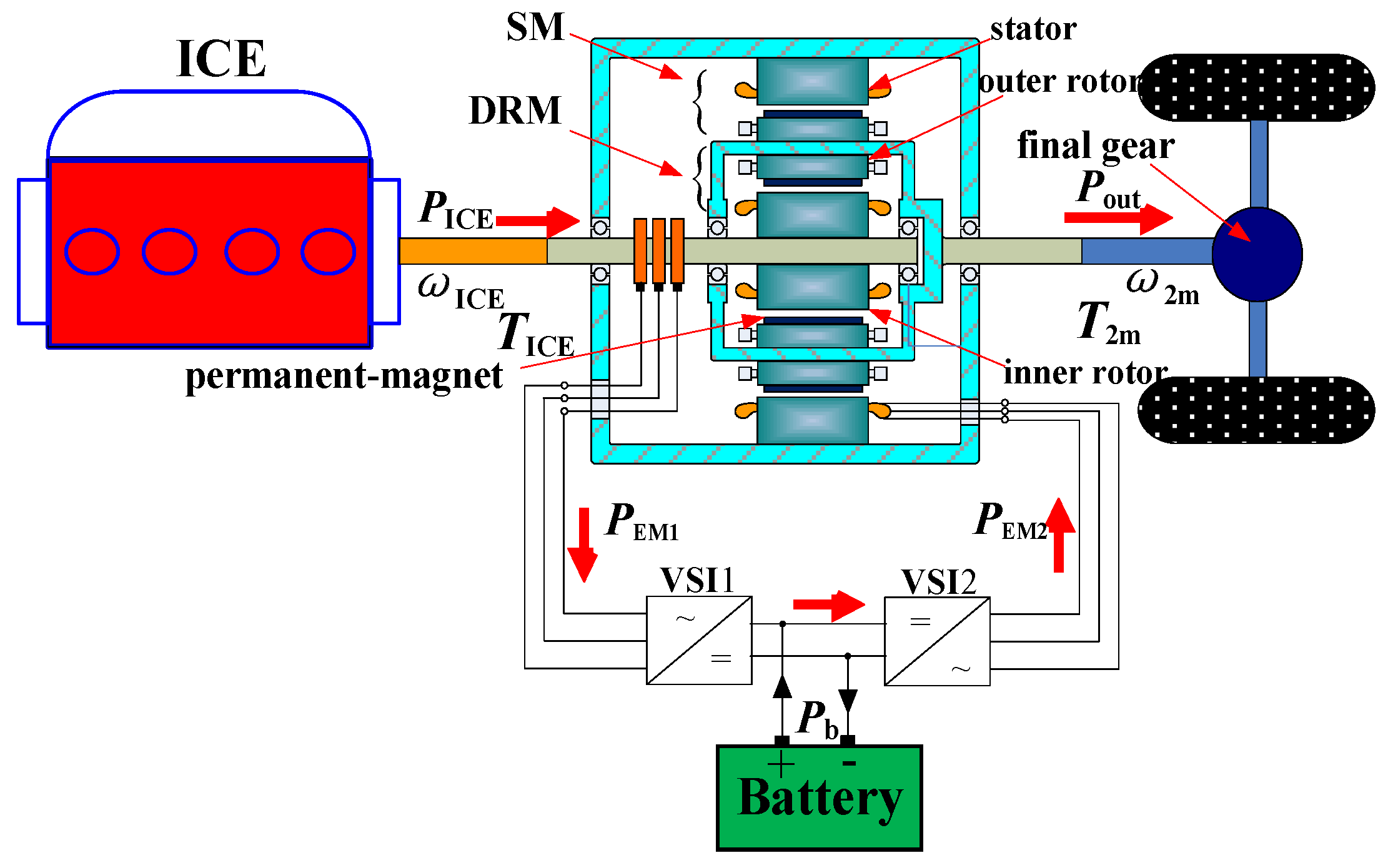
The CSPM motor is composed of three parts, which are a stator with three-phase windings, an outer rotor with permanent magnets on the inner and outer surfaces and an inner rotor with three-phase windings. The stator and outer rotor with outer surface permanent magnets constitutes the stator motor (SM), which is also called EM2 (electric motor 2), and the outer rotor with the inner surface permanent magnets and inner rotor forms the double rotor motor (DRM), which is also called EM1 [
7]. The schematic structure of the HEV based on the CSPM motor is shown in
Figure 1. The high degree of integration between DRM and SM makes up the CSPM motor system, which is between the ICE and final gear. The inner rotor is coaxial with the ICE, and the outer rotor is connected to the final gear in the HEV, which has two independent mechanical output shafts. From
Figure 1, we can see that there is no mechanical link between the ICE and final gear, which makes the two parts isolated completely to operate better. This new structure integrates the function of the mechanical power distribution devices in the Prius, such as the generator, motor and planetary gear. It can simplify the energy flows to become a pure electric power distribution device, and the entire system structure is more compact and has flexible control, opening up a new direction for the HEV field [
8].
The CSPM motor system’s function, due to the special structure of the double shafts, is not inferior to the Prius transmission system under the same characteristic parameters [
9]. If the output shafts take turns connecting to the ICE or final gear, the different functions of the hybrid power and modes of energy flows are realized. Under the auxiliary adjustment of the CSPM motor, the speed and torque control of ICE can be realized at the same time, and the speed continuous changes of the transmission are simulated. It can be used as an electric variable transmission (EVT), so the operation modes of the system can switch automatically to keep the ICE working at the highest efficiency in different conditions, increasing efficiency, reducing pollution and fuel consumption. The HEVs will become the mainstream car to ease the problems of resources and environment in the future.
2.1. Comparative Analysis of CSPM Motor and THS of Power Split HEVs
THS is the core of the transmission system in the Prius series HEVs, which was launched by Toyota Corporation in 1997 [
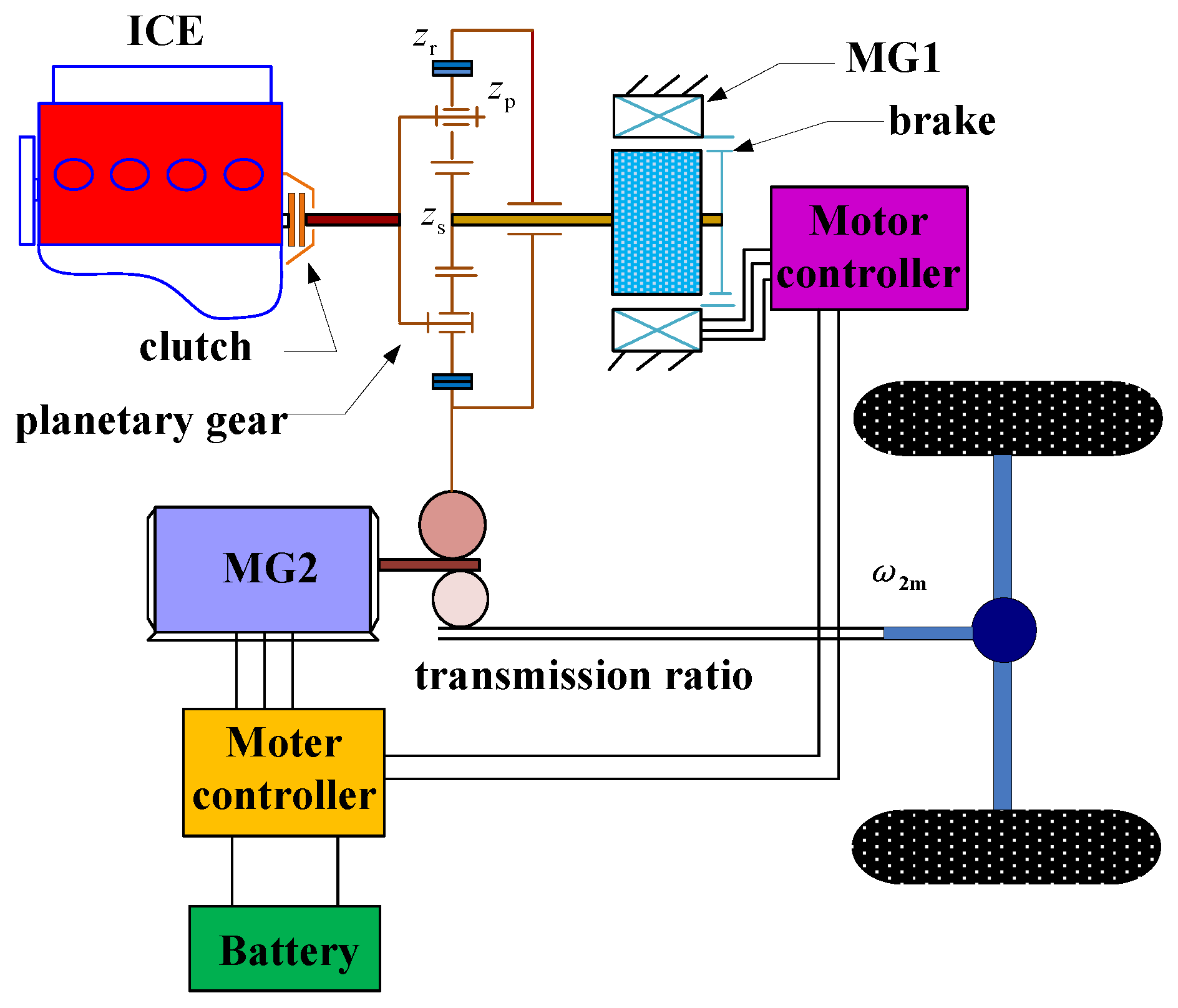
10]. The speed and torque couplers of THS is a planetary gear, which realizes the functions of electromechanical coupling, power distribution and energy flows in the hybrid power system, solving the difficulty of dynamic coupling in HEVs. The structure diagram of the Prius power transmission system is shown in
Figure 2.
In
Figure 2, the output shaft of ICE is connected to the carrier of the planet gear, then the output power is transmitted to the sun and ring gears, respectively. The sun gear is connected to the generator (MG1, (motor generator1)), which can be used as the input or output port. The ring gears act as an output port connected to the motor (MG2) and transmission shaft through a torque coupler. Most output energy of the ICE is engaged with the ring gears through the carrier, which transmits the energy to the driving shaft; while the rest of the energy is transmitted to the MG1 by the mechanical coupling of the carrier and sun gears. The mechanical energy is converted into electrical energy in MG1 to charge the battery or supply MG2, then the driving force is increased. The planetary gear system can be regarded as a torque coupler, which transmits the driving force to the wheel [
11]. The speed relationship of the carrier and sun ring is shown in Equation (1):
where
ωr is the speed of carrier;
ωp is the speed of the ring gear;
ωs is the speed of the sun gear;
ρ =
Nr/
Ns is the basic ratio of the tooth number (the ratio of the ring and sun gears).
In the HEV, MG1 and MG2 can be used as the control devices of speed and torque, respectively. When the power of the system is allocated, the speed and torque of ICE is adjusted by the control of the central controller. The speed of the three power sources is controlled selectively, i.e., ICE, MG2 and MG1, to simulate the continuous change of the transmission ratio. Therefore, the whole system can be used as an EVT and switch to the best driving mode to suit the road conditions automatically. All parts of this system can work in the optimal area in various conditions, achieving energy optimization matching to reduce emissions and fuel consumption. Most companies use the planetary gears as a hybrid power system. However, the planetary gear is a purely mechanical device, which has serious vibration and noise, high loss and needs regular lubrication, limiting the further application in HEVs.
The diagram of the energy flows in the Prius hybrid power system is shown in
Figure 3.
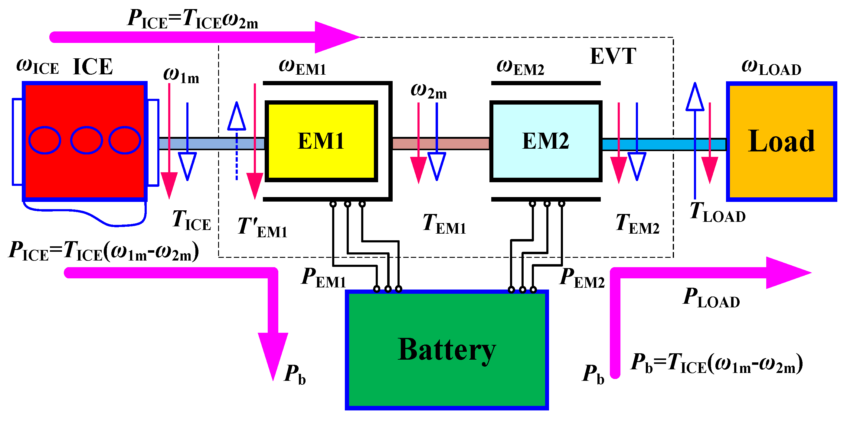
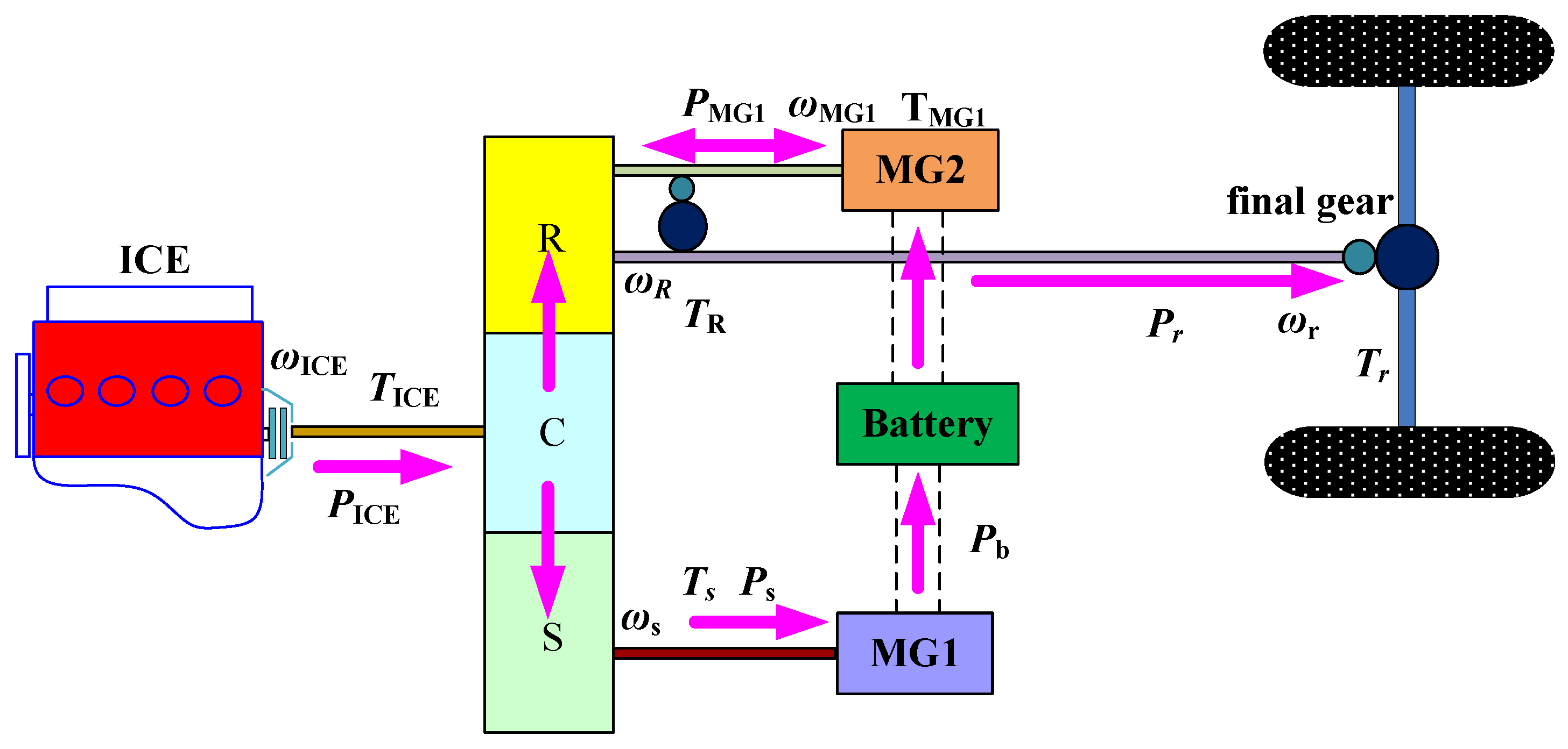
The CSPM motor is another power coupling mechanism with two mechanical ports and two electrical ports, which is different from the planetary gear. The unique configuration provides more compactness, thus making the full hybrid function come true. The CSPM can realize the function of the powertrain in the HEV. In addition, the CSPM can also be used as a converter of torque and speed to adjust the ICE to run in the most economical efficiency area. The energy flows are more flexible, and dynamic coupling of the transformation system is more powerful, which has a broad prospect in the application of the HEV. The diagram of the energy flow in the HEV based on the CSPM motor is shown in
Figure 4.
The output mechanical energy of ICE (PICE) is divided into two parts, as shown in Equation (2); a part of the energy is the output power of EM1 (electric motor1) (PEM1) directly passed to the stator of EM2, through the collector ring, brush, rectifier and inverter. Another part of the energy (Pr) is transmitted to the output shaft through the magnetic field, driving the outer rotor of EM1 directly.
The inner rotor of EM1 is mechanically connected to the output shaft of the ICE. In a stable state, the speed of the inner rotor of EM1 is equal to the speed of the ICE (
ωICE), and the electromagnetic torque of EM1 (
TEM1) is balanced with the output torque of the ICE (
TICE). Thus, we can get Equation (3):
The output shaft of the CSPM motor is connected to final gear of the HEV, and the output speed of EM2 (
ωEM2) is determined by the speed of the HEV. The output torque of the outer rotor (
T2m) is the torque combined from EM1 and EM2, as shown in Equation (4):
According to the above analysis, both the THS of the Prius series HEVs and the power transmission device of the CSPM motor can realize the output power split of the ICE. We use the
ωEM1,
ωEM2,
ωMG1,
ωMG2 to express the speed of EM1, EM2, MG1, MG2;
TEM1,
TEM2,
TMG1,
TMG2 to express the torque of EM1, EM2, MG1, MG2, respectively;
TICE,
Td to express the torque of ICE and driving shaft;
ωICE,
ωd as the speed of ICE and driving shaft and the power transmission system mathematical models of THS and the CSPM motor are compared, as shown in
Table 1.
2.2. Parameter Matching Between the CSPM Motor and the Prius System
2.2.1. Parameter Matching of SM in the CSPM Motor
As shown in
Table 1, the torque coupling relationships between the Prius system and the driving shaft of the CSPM motor are obtained by Equations (5) and (6):
If we connect a gear with a speed ratio of (1+ ρ)/ρ after the ICE of the CSPM motor, then the new torque coupling relationship of the ICE can be computed in Equation (7):
Comparing Equation (5) with Equation (7), we can know that, if the two torques of the ICE are the same, when Td1 = Td2, then TMG2 = TEM2, i.e., completing the torque matching of EM2.
From Equations (8) and (9), it can be seen that EM2 and MG2 have the same speed association constraints, which are equal to the speed of the driving shafts, respectively. Under the same speed of driving shaft, the speeds of EM2 and MG2 are equal, as shown in the Equation (10):
According to the above analysis, the parameter matching of torque and speed between the MG2 of the Prius system and the EM2 of the CSPM motor is realized, and the power parameters of the two motors are also equal.
2.2.2. Parameter Matching of DRM in the CSPM Motor
From
Table 1, it can be known that the original speed coupling relationship of ICE in the CSPM motor is shown in Equation (11):
After the ICE is connected to the deceleration gear, the new speed coupling relationship becomes:
The speed coupling relationship of the generator (MG1) in the Prius system, as shown in Equation (13):
Then, we multiply both sides of Equation (13) by the proportional coefficient (1 + ρ)/ρ, and Equation (14) is obtained:
Comparing Equation (12) with Equation (14), it is clearly seen that when the speeds of the ICE in the Prius system and the CSPM motor are same, the speed relationship between the MG1 and EM1 is shown in Equation (15):
Because the ICE is connected with a reduction gear, the new torque coupling relationship is:
The torque of MG1 is multiplied by the proportional coefficient; the new coupling relationship can be deduced from Equation (17):
Contrast Equations (16) and (17); when the torques of the ICE are the same in the two systems, the torque relationship of EM1 and MG1 can be obtained:
It can be seen in Equations (15) and (18), after the parameter matching, that the speed of CSPM motor is reduced to 1/ρ of the Prius system, and the torque is ρ times the Prius system. Therefore, the power of the CSPM motor and the Prius system is equal.
2.2.3. Verification of Parameter Matching
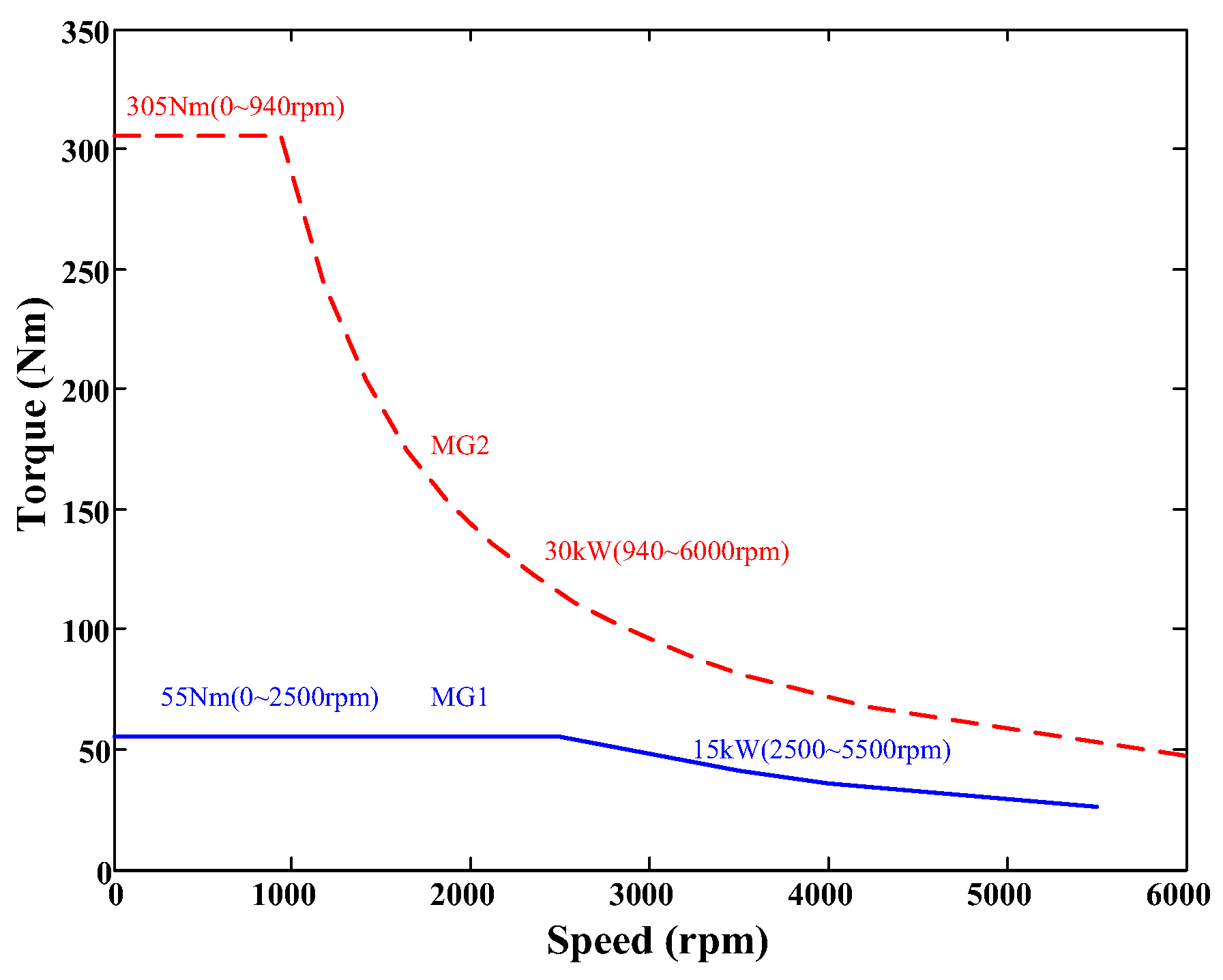
The torque and speed curves of MG1 and MG2 in the THS are shown in
Figure 5.
According to the parameter matching proposed in this paper, the design parameters of the CSPM motor with the same dynamic performance as the THS (Toyota Hybrid System) are obtained, as shown in
Table 2.
By connecting a gear with a transmission ratio of (1 + ρ)/ρ to the output shaft of the ICE, the parameters between MG2 and EM2 are consistent. The maximum torque of EM1 is ρ times that of MG1, and the maximum speed of EM1 is reduced to ρ times that of MG1.
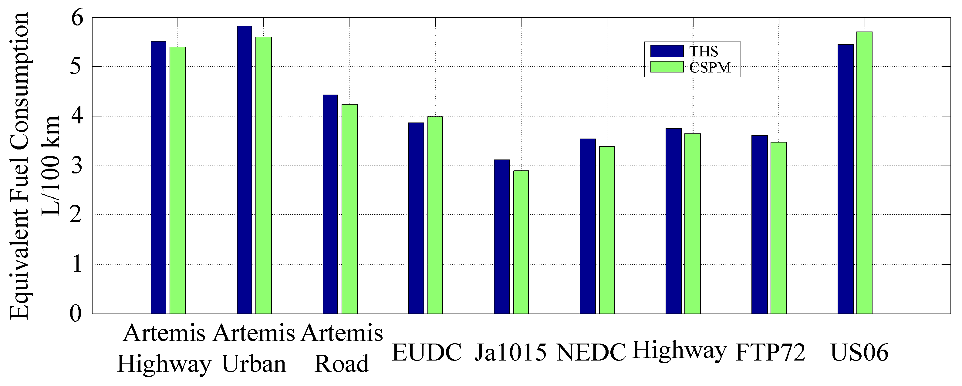
Then, we put the design parameters of the CSPM motor into the simulation model to calculate the power performance and fuel economy of the HEV. The dynamic performances and fuel economy between the HEVs based on THS and the CSPM motor are compared, as shown in
Table 3 and
Figure 6.
The dynamic performances and fuel economy of the HEVs based on the CSPM motor have been improved slightly under the comparison with the Prius system, which shows the reasonableness and effectiveness of the design method.
3. Equivalent Magnetic Circuit Analysis of the CSPM Motor
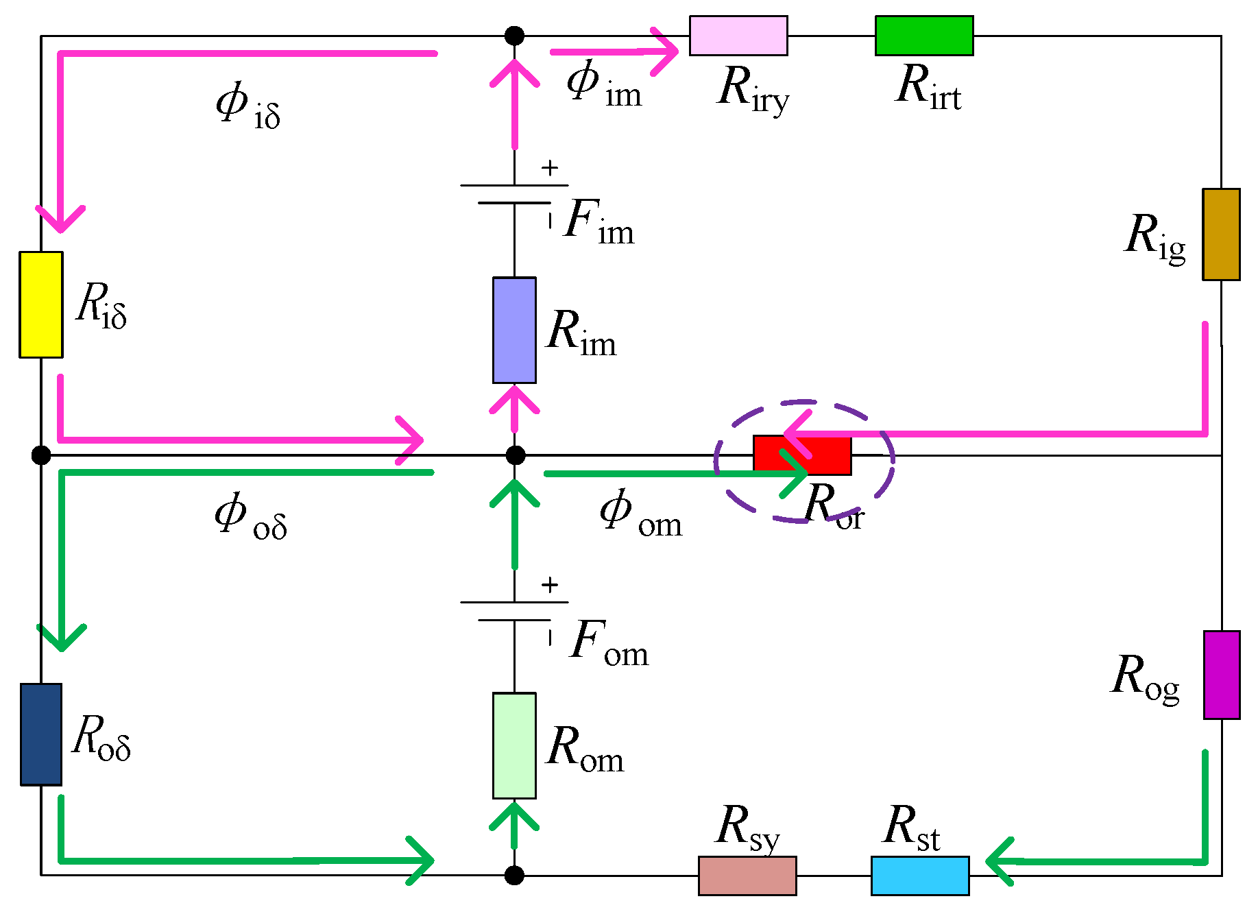
According to the literature [
12], when the two-layer permanent magnets are adopted for a consistent magnetization direction, the no-load equivalent magnetic circuit is as shown in
Figure 7.
Fim, Fom are the equivalent magnetic motive forces produced by the inner and outer layer permanent magnets; φim, φom are the main magnetic fluxes in the DRM and SM; φiδ, φoδ are the equivalent leakage fluxes in the inner and outer layer permanent magnets; Rim, Rom are the equivalent reluctances of two-layer permanent magnets; Riδ, Roδ are the equivalent leakage reluctances of two-layer permanent magnets; Riry, Rirt are the yoke, teeth reluctances of the inner rotor; Rsy, Rst are the yoke, teeth reluctances of the stator; Rig, Rog are the reluctances of the inner and outer air-gap; and Ror is the reluctance of the outer rotor.
According to
Figure 7, the mesh loop equations are analyzed on the basis of the network equation method in circuit analysis, as shown in Equation (19):
where:
According to Equations (19) and (20), the main magnetic fluxes in the DRM and SM are computed in Equations (21) and (22):
As the magnetic fluxes of the outer rotor are in opposite directions, so we can derive the total magnetic flux of the outer rotor from Equations (21) and (22), as shown in Equation (23):
where:
According to
Figure 7, in order to decrease the saturation degree of the outer rotor, we should keep the magnetic motive force unchanged to reduce the magnetic flux in the outer rotor. Therefore, the main magnetic fluxes of DRM and SM flowing through the outer rotor are not limited, i.e., realizing the magnetic decoupling of DRM and SM.
From Equation (24), we can see that Ri3 includes Rig, Riδ and Ro3 includes Rog, Roδ. Considering that the magnetic circuit of the air-gap and magnetic leakage circuit of the permanent magnets are closed through the air, which is a non-conducting magnetic material with a much larger reluctance than the magnetic material, so we assume that Ri3 » Ror, Ro3 » Ror.
Thus, the expression of the total magnetic flux in the outer rotor can be approximated as Equation (7):
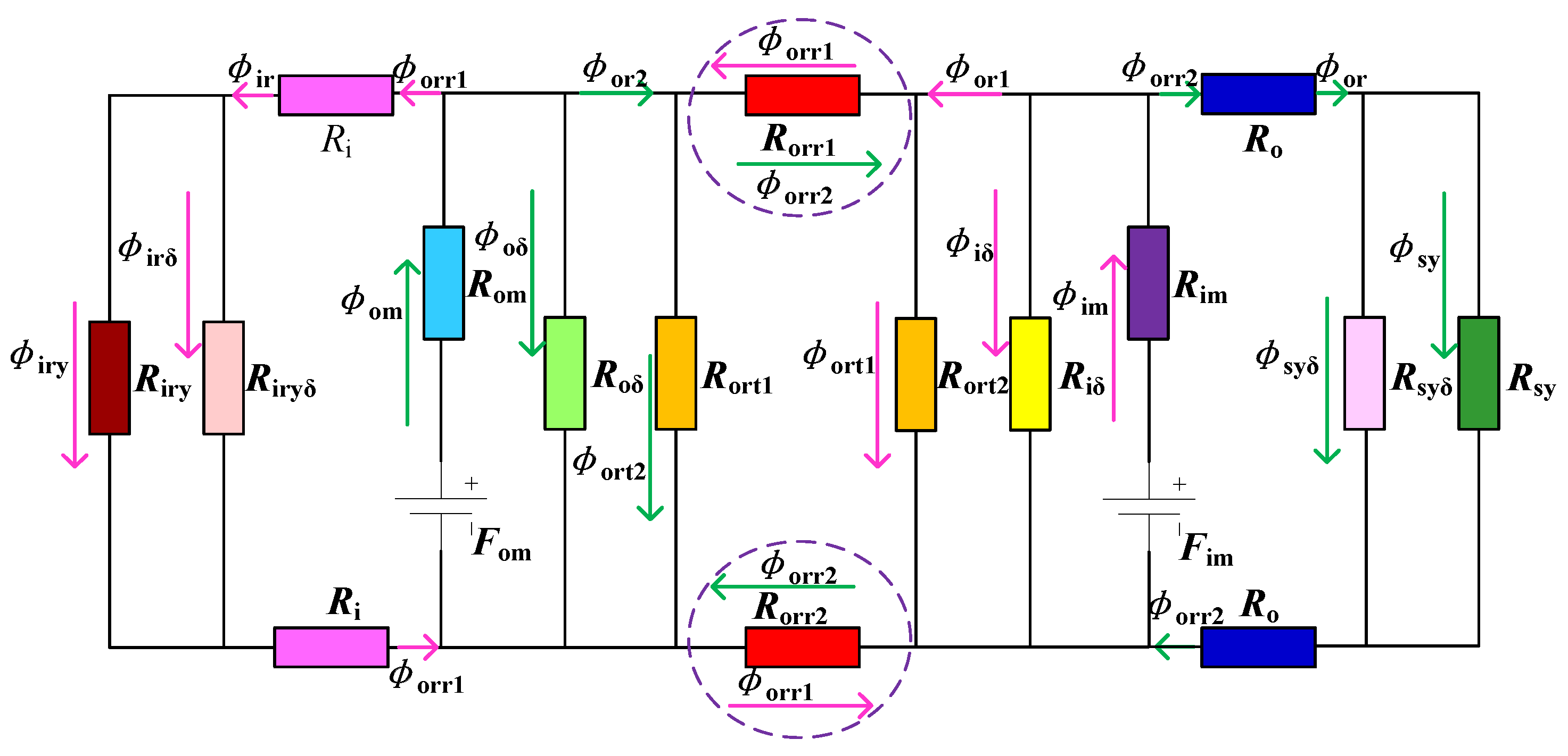
The outer rotor of the CSPM motor has a certain thickness, so the magnetic fluxes generated by the two-layer permanent magnets and stator armature reaction flow in the outer rotor will be divided into two paths, i.e., radial and tangential. Tangential magnetic flux is the main magnetic flux, transmitting the electromagnetic energy; the other is the coupling magnetic flux of DRM and SM, which is proportional to the coupling degree. The no-load equivalent magnetic circuit of the tangential and radial magnetic fluxes in the outer rotor is described in
Figure 8.
Rorr1, Rorr2 are the equivalent radial reluctances of the outer rotor under the magnetic fluxes of DRM and SM; Rort1, Rort2 are the equivalent tangential reluctances of the outer rotor under the magnetic fluxes of DRM and SM; Ri, Ro are the total equivalent reluctances of the inner and outer air-gap; Rirδ, Rsyδ are the equivalent yoke leakage reluctances of the inner rotor and the stator; φor1, φor2 are the total magnetic fluxes of the outer rotor generated by DRM and SM; φorr1, φorr2 are the radial magnetic fluxes of the outer rotor generated by DRM and SM; φort1,φort2 are the tangential magnetic fluxes of the outer rotor generated by DRM and SM; φir is the magnetic flux of the inner rotor from the inner layer magnets; φor is the magnetic flux of the stator from the outer layer magnets; φiry, φsy are the yoke magnetic fluxes of the inner rotor and the stator.
When the leakage resistances of the inner rotor, stator and two-layer permanent magnets are neglected, the equivalent magnetic motive forces of the two-layer permanent magnets are expressed in Equations (26) and (27):
where:
From Equations (26) and (27), the radial and tangential flux ratios of the inner and outer permanent magnets are computed in Equation (29):
As 2
Ri »
Riry + 2
Rorr1 and 2
Ro »
Rsy + 2
Rorr2 simplify Equation (29), we can get the radial coupling magnetic fluxes of the outer rotor generated by DRM and SM, as shown in Equations (30) and (31):
From the above mathematical analysis, in order to perform the magnetic decoupling of two motors, we should reduce the total magnetic flux in the outer rotor, which is divided into tangential and radial. The radial magnetic flux is the coupling flux between DRM and SM, which should be reduced as far as possible under the required electromagnetic energy. From Equations (30) and (31), we can see that, keeping the main magnetic fluxes unchanged, φorr1 is only associated with Rort1, and φorr2 is only associated with Rort2. Therefore, the magnetic decoupling can be realized if we reduce the tangential reluctance of the outer rotor, i.e., increasing the yoke thickness of the outer rotor properly.
4. Magnetic Coupling Characteristics’ Analysis of CSPM
4.1. Analysis of the Magnetization Direction
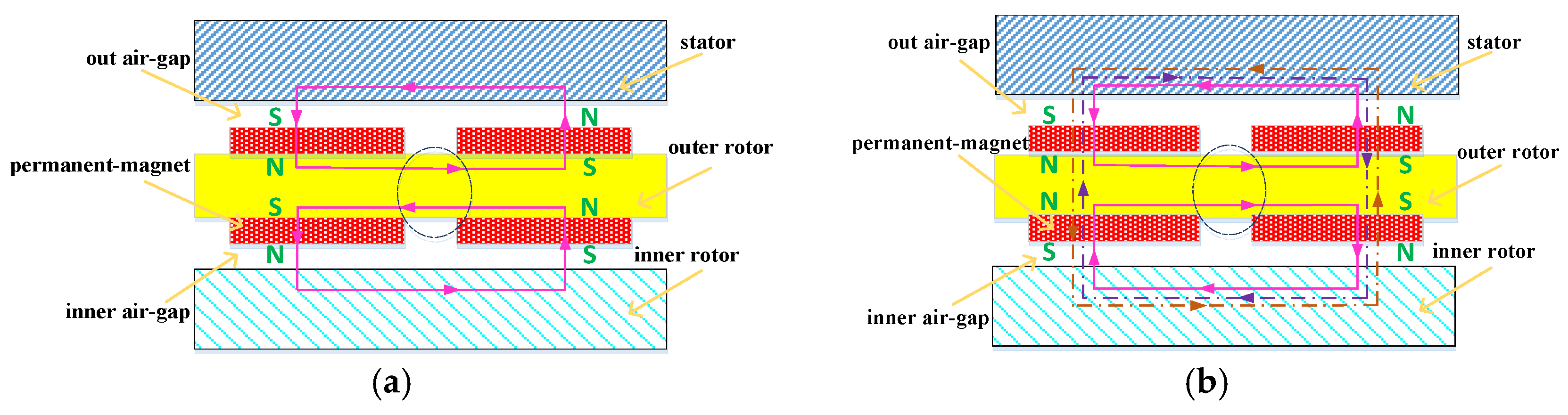
On both sides of the outer rotor are placed permanent magnets, the magnetization direction of which can be divided into consistent and opposite. In the consistent magnetization direction, the flux line directions in the outer rotor produced by DRM and SM are opposite, which can offset each other, as shown in
Figure 9a. When the two magnetic fields in the outer rotor are similarly, the magnetic flux in the outer rotor is less after offsetting. Thus, we can reduce the yoke thickness of the outer rotor properly, without considering the influence of saturation.
When in the opposite magnetization direction, the magnetic flux directions in the outer rotor are the same, i.e., the magnetic fields overlap each other. This makes the outer rotor easily saturated, and the magnetic flux of DRM will flow into SM and vice versa, as shown in
Figure 9b. The original flux lines of the two motors are crippled, and the operations are disrupted. At this point, we must increase the yoke thickness of the outer rotor to reduce the saturation degree and nonlinear magnetic field.
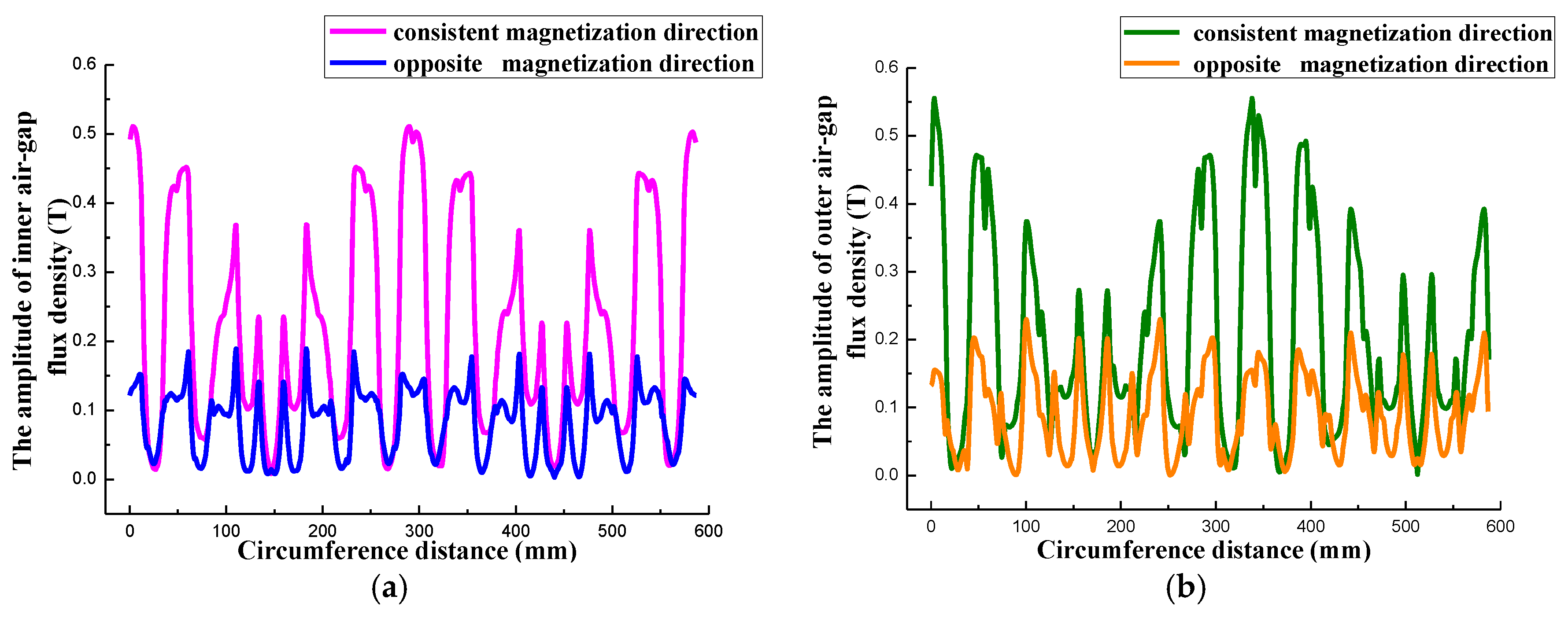
In order to analyze the influence of magnetization directions further, the amplitudes of the air-gap flux density curves of the inner and outer air-gap in different magnetization directions are shown in
Figure 10.
We can easily see that the air-gap flux density of SM is higher than DRM in the two kinds of directions, i.e., the magnetic coupling has a greater influence on DRM. The influence of the consistent direction is quite different from the opposite, the former of which is larger. This shows that the two amplitudes of the air-gap flux density are crippled, under the opposite magnetization direction. That is, the original magnetic flux through the outer rotor forms a closed circuit; but, some lines of DRM will now enter into SM, and some lines of SM will enter into DRM. Part of the original work of magnetic flux is offset, and the outer rotor is in a serious saturation state. To realize the magnetic decoupling, we can increase the yoke thickness of the outer rotor or reduce the length of the air-gap, but the power density and magnetic properties of the two motors will be reduced. The reverse lines of the outer rotor can partially offset each other in the consistent magnetization direction, which greatly decreases the saturation degree. The main magnetic fields of the two motors are independent, so the resistances of the whole circuit are small, which increases the flux density of the air-gap.
Therefore, to reduce the saturation degree and yoke thickness of the outer rotor properly, the consistent magnetization direction of the two-layer permanent magnets should be adopted.
4.2. Design the Yoke Thickness of the Outer Rotor
The magnetic fields of DRM and SM are closed through the outer rotor, which provides both the magnetic circuits and magnetic motive forces to the motors. Accordingly, there are mechanical coupling and electromagnetic coupling between the two motors, and the electromagnetic coupling is more serious. Therefore, it is particularly important to opt for a suitable yoke thickness of the outer rotor. Increasing the thickness will gradually reduce the coupling degree between the DRM and SM. The magnetic fluxes are through the outer rotor, then back to the air-gap, respectively, and the interference in the magnetic fields is very small. If the yoke thickness is too thick, the quality and volume of CSPM are increased, leading to inconvenience in the mounting. This will also reduce the power density and work efficiency, leading to the advantages of the CSPM motor not being fully revealed. The outer rotor is easily saturated when the thickness is too thin, which leads to the changes of inductance and resistance, and the magnetic coupling is serious. Moreover, the control difficulty of DRM and SM is increased, i.e., the control goals are hard to achieve, which causes the degradation of the performance.
Therefore, in order to accomplish the magnetic decoupling of the CSPM motor, the key of the design is to select a proper yoke thickness of the outer rotor. This will realize the independent control of the two motors and make full use of the excellent performance of the CSPM motor.
4.2.1. Analysis of the Outer Rotor Based on the Finite Element Method
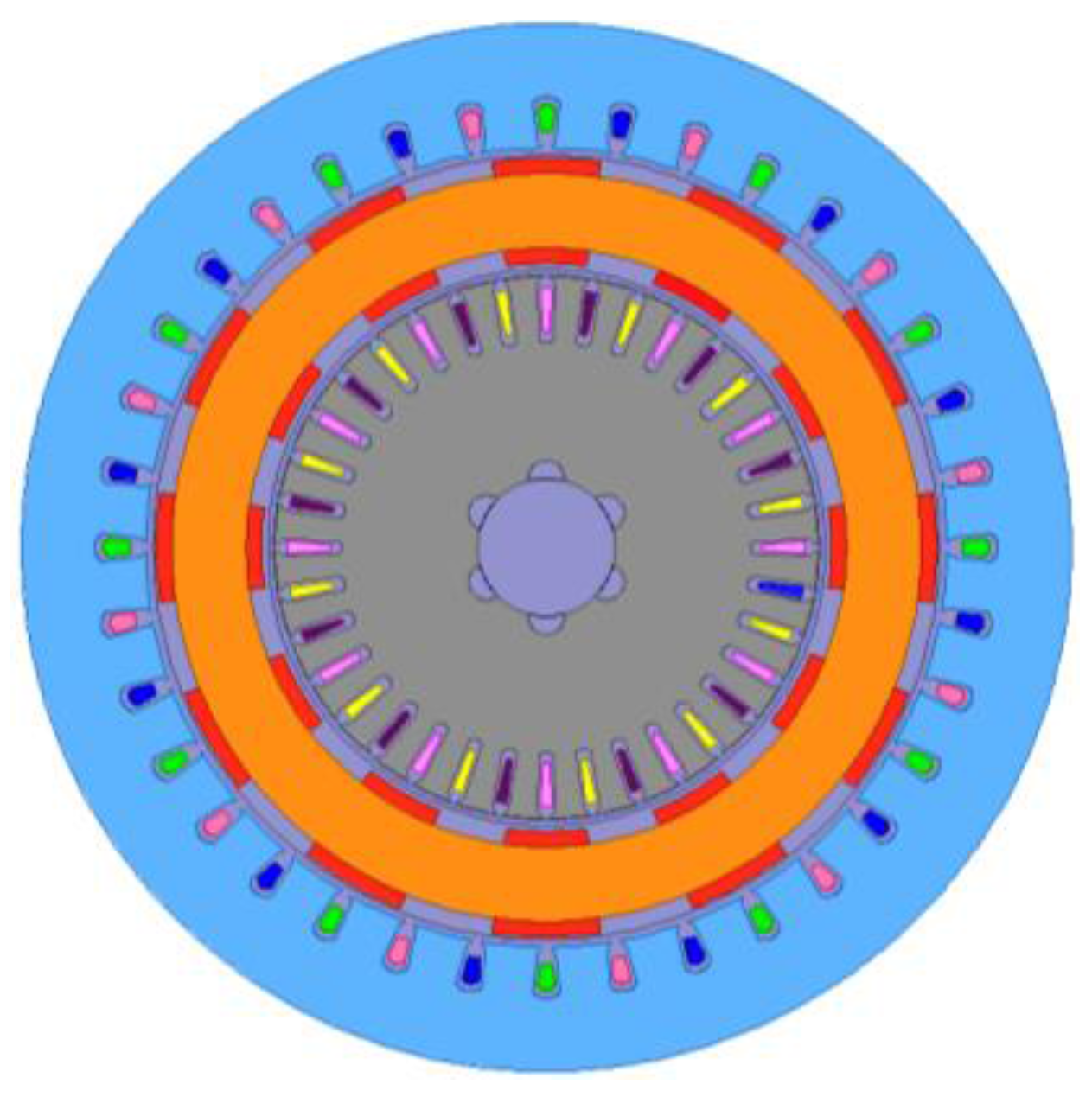
The finite element method (FEM) model of the CSPM motor is established in
Figure 11.
Serious magnetic field saturation is aimed at the outer rotor, with the premise of achieving the same dynamic performance to determine the design parameters of the CSPM motor based on the parameter matching of the Prius series HEVs. The electromagnetic field FEMs of DRM and SM are established, and the electromagnetic simulation calculations are carried out [
13], which provide a reference for the electromagnetic design of the CSPM motors. The simulation parameters of the CSPM motor are shown in
Table 4.
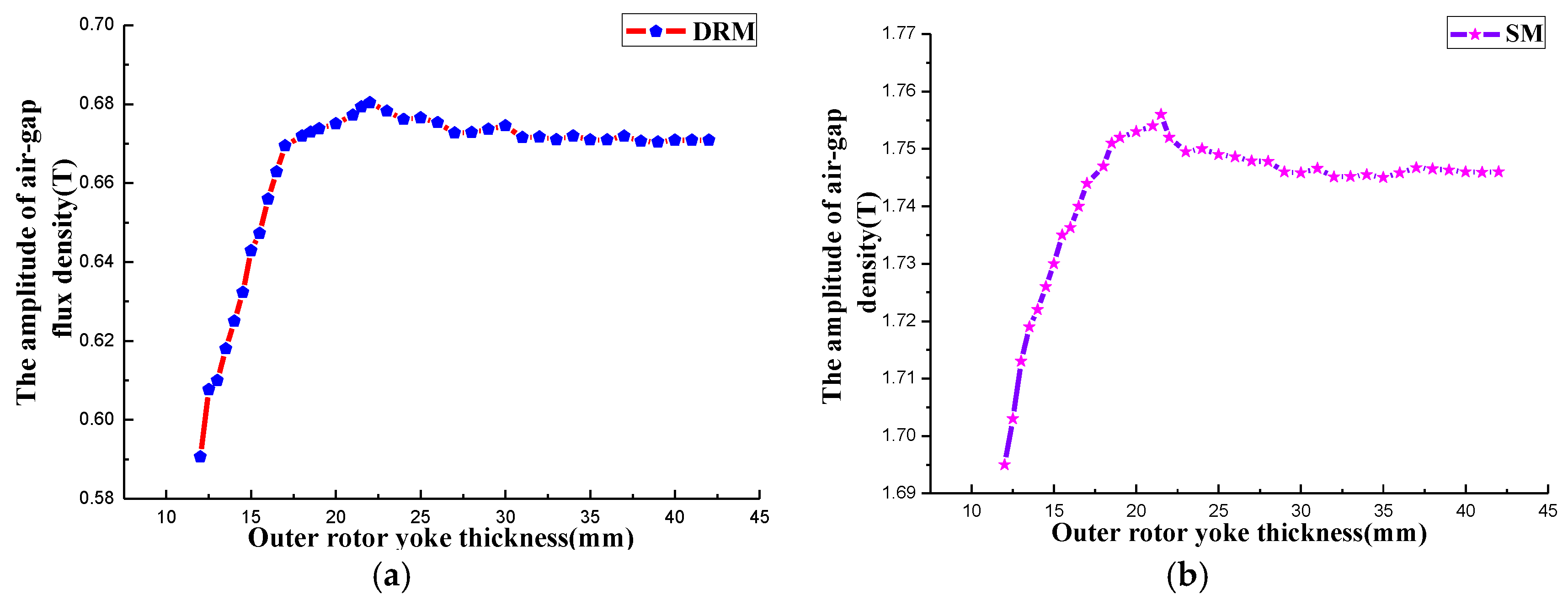
Accurate analysis of the distribution of the air-gap magnetic field is the key to study the magnetic properties of CSPM. From the above analysis, we can know that the magnetic flux in the outer rotor is proportional to its resistance, which can be changed by the yoke thickness. Meanwhile, the air-gap flux density can be influenced by the saturation degree of the outer rotor, so we use the air-gap flux density to reflect the magnetic flux in the outer rotor. By changing the yoke thickness of the outer rotor, the curves of the air-gap flux density amplitude in the DRM and SM are shown in
Figure 12.
It can be seen in
Figure 12 that along with the yoke thickness of the outer rotor changing, the variation trends of the air-gap flux density amplitude in the DRM and SM are similarly. The amplitude of SM is higher than DRM, which is caused by the higher rated power. The maximum value of the air-gap magnetic density amplitude is achieved when the yoke thickness of the outer rotor is 22 mm. If the thickness is below 22 mm, the air-gap flux densities of the two motors drop rapidly, and when over 22 mm, the flux densities have little difference.
The flux lines of DRM and SM go through the air-gap into the outer rotor and then return, respectively. Therefore, the smaller the air-gap flux density amplitude is, the more non-linear the outer rotor is. The radial magnetic flux flows into the air-gap more easily, i.e., the radial magnetic flux produced by the inner layer permanent magnets flows into SM, and that produced by the outer layer permanent magnets flows into DRM; the original flux lines are offset. This will cause the great decrease of the air-gap magnetic density amplitude and magnetic properties.
Therefore, if we want to reduce the saturation degree of the outer rotor to realize decoupling, the yoke thickness of the outer rotor with the large air-gap flux density should be selected. We can see that in
Figure 8, the air-gap magnetic density is higher when the yoke thickness is greater than 22 mm, that is the DRM and SM are decoupled. However, in order to meet the requirements of being lightweight and the miniaturization of the CSPM motor, we choose 22 mm as the yoke thickness of the outer rotor.
4.2.2. Verification of the Finite Element Method Analysis
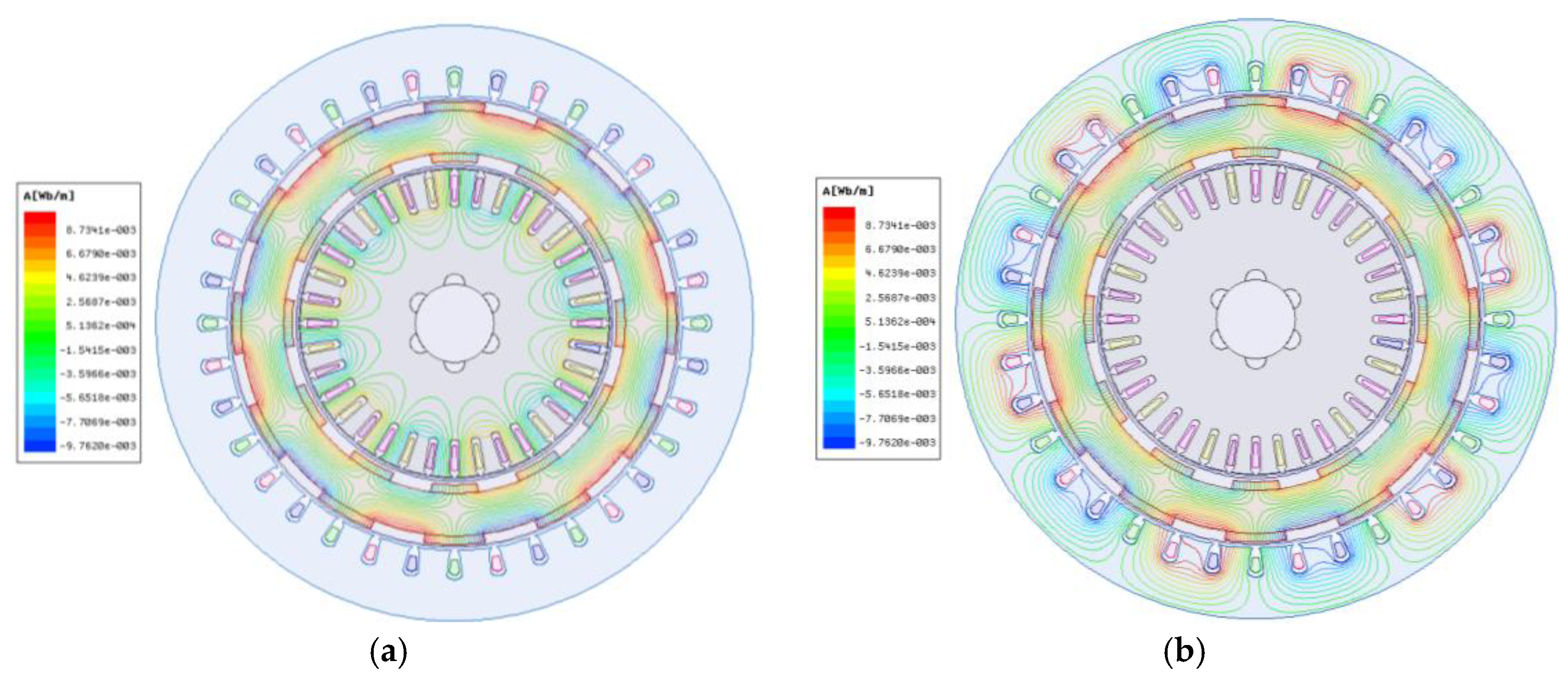
According to the selected yoke thickness of the outer rotor and the design parameters of DRM and SM, we establish the electromagnetic simulation model based on 2D-FEM. Then, the magnetic field distribution diagram of the CSPM motor is obtained, as shown in
Figure 13.
From
Figure 13, it can be clearly seen that when the SM and DRM work alone, the flux lines of the two motors have no cross by choosing the appropriate yoke thickness of the outer rotor. Only a small part of the leakage magnetic flux of SM flows into the DRM, and vice versa. When the two motors operate together, there are few radial coupling magnetic fluxes in the outer rotor.
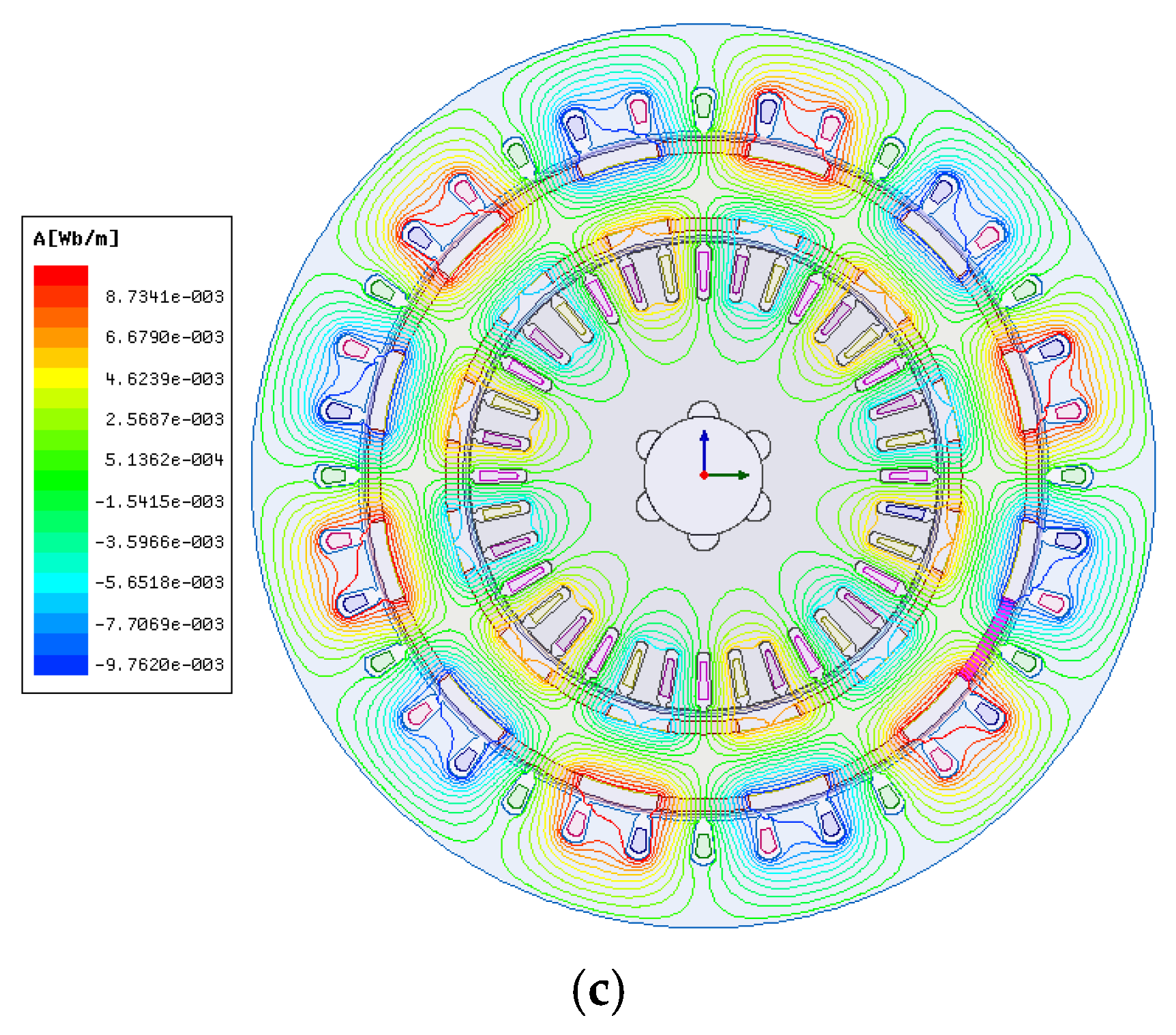
Figure 13c shows the numerical value of the magnetic field intensity of CSPM. We are aware that the values of the stator slots and inner rotor slots are huge, while in the stator and outer rotor yoke, the numerical value of the magnetic field intensity is small. Thus, the two motors can work without interference. At this time, the magnetic coupling degree of the two motors is very small and even can be ignored, i.e., the magnetic decoupling of the CSPM motor is complete. The control difficulty is decreased, and the output torque and power density are increased. Coupled with the appropriate control strategy, the excellent performance of the CSPM motor can be realized. This also avoids a large volume of the device, so further demonstrating the validity of the internal magnetic decoupling scheme, which provides a reference for the optimization design of the CSPM motor.


