1. Introduction
With the rapid development of battery technology, from the hybrid electric vehicle (HEV) to the battery electric vehicle (BEV), the automobile is gradually moving away from dependence on fossil fuels. However the energy density and the speed of energy supply a battery possesses are far lower than those of petrol [
1]. As a result, the electric vehicle (EV) is characterized by inconvenient and frequent charging, a bulky battery pack and limited driving range.
In order to remove the need for the charging cable, researchers have investigated EV static wireless charging (EVSWC) technology when an EV stops at the assigned position. Compared with the cable charging method, the EVSWC system is more convenient and can avoid electric sparks and worn circuits. The studies of EVSWC technology mainly cover efficient high-frequency inverters in primary side, effective high-frequency rectifiers in secondary side, electromagnetic couplers with high lateral misalignment tolerance, novel compensation circuits in both primary side and secondary one, and interoperability of different EV wireless charging equipment. The design and implementation of a wireless power transfer battery charger for an electric city car is presented in [
2]. A 2 kW 700 mm-diameter pad, with a horizontal radial tolerance of 130 mm with a 200 mm air gap, was constructed and tested in [
3]. A double D (DD) coil and a unipolar coil are selected for the study in [
4]. In [
5], a compensated coil is integrated into the main coil structure, and a system with the proposed integration method is able to transfer 3.0 kW with an efficiency of 95.5% at an air gap of 150 mm. The series LC (SLC) resonant and the hybrid series-parallel (LCL) resonant full-bridge inverter topologies used for wireless electric vehicle (EV) charging are comparatively studied in [
6]. The interoperability between different systems of contactless EV battery static charging by means of inductive coupling is investigated in [
7].
Furthermore, to solve the issues of bulky battery and limited driving range, and to develop new energy storage devices with higher energy density, researchers have put forward the EV dynamic wireless charging technology (EVDWC), which can supply electricity for a running EV. EVs tend to have a limited driving range because of the restricted number of battery. With the application of dynamic wireless charging technology, EVs can be powered wirelessly while running. As a result, the size of the battery will decrease and in theory the car could even run without battery. A typical EVDWC system consists of the wireless power transmission unit, electric automobile unit and coordinated control unit [
8]. The primary structures of EVDWC systems can be divided into a single long coil structure and a multiple short-segmented coil structure. The researches about systems with a single long coil structure mainly focus on modeling methods, novel coil structures and electromagnetic radiation elimination methods. A system with a single long coil structure is modeled on Laplace phasor transform in [
9]. Hao et al. [
10] build the approximate dynamic model of EVDWC system with LCL-T structure by using the generalized state-space averaging method. The research team at the University of Auckland proposes a three-phase wireless power transmission structure for EVDWC [
11]. Researchers in KAIST (Korea Advanced Institute of Science and Technology) devote themselves to designing the coils structures of primary and secondary sides [
8] and finding the electromagnetic radiation elimination methods [
12]. Compared to a system with a single long coil structure, a system with a multiple short-segmented coil structure depends on EV positioning technology and switching control method of multiple primary coils. Bertoluzza et al. [
13] investigate the coupling characteristics of double D (DD) coils with different dimensions in a short-segmented coil structure system. In [
14], an efficiency of 92.5% at an output power of 5 kW is achieved with the application of a double-coupled configuration in a short-segmented wireless charging system for EV. An EVDWC system with a simultaneous two-transmitter method is proposed to obtain constant power supply in [
15]. Kibok et al. [
16] investigate characteristics of the received power changing with the position of the secondary coil in EVDWC systems with multiple short-segmented coils.
Because of many factors including existing technology and relevant policies about road reconstruction, there are still many problems to be solved before promoting the practical application of EVDWC systems in a short timeframe [
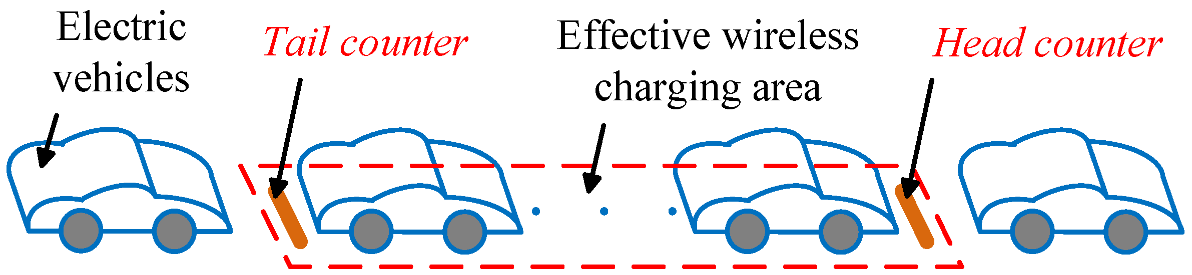
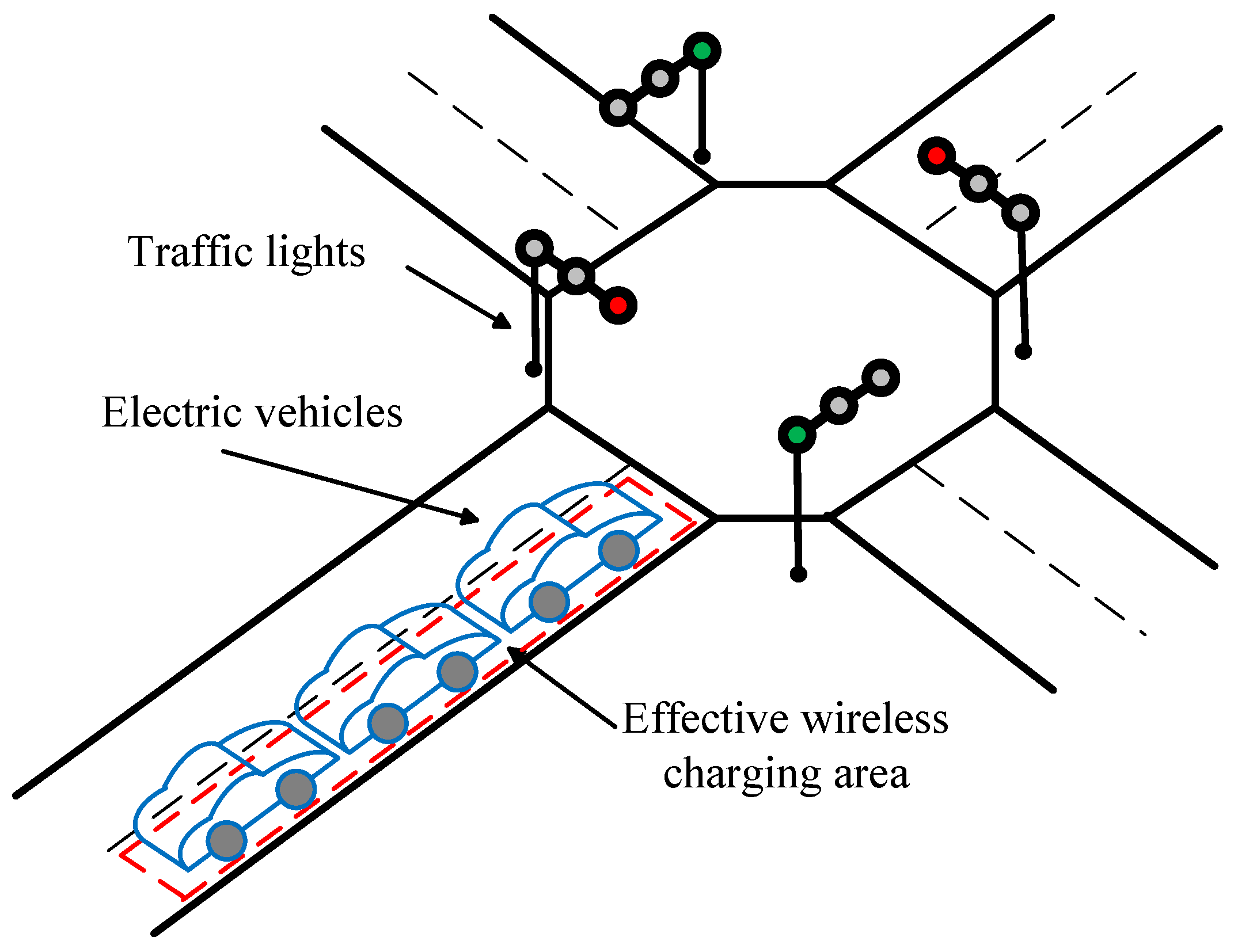
17]. However, we can turn our attention to road junctions at traffic lights and build an opportunity wireless charging system for electric vehicles there. This opportunity wireless charging system at traffic lights is a combination of EVSWC and EVDWC. EVs can enter the waiting area that is also the opportunity wireless charging area and be charged conveniently while they wait for the traffic lights. This method contributes to enlarging driving range and is the basis of a whole-road EVDWC system.
Unlike the existing EVSWC system, the EV wireless charging system at traffic lights will need to solve two main problems. Firstly, due to the fact that waiting time cannot be very long (usually between 30 s and 100 s), the rate of the charging power is expected to need to be several kilowatts so that charge the battery in a short time. According to advanced EVDWC technology, the system can generate a high rate of charging power [
8]. Another problem caused by the random access loads in the system is studied in this paper: On the one hand, if the power source voltage is constant, the access process of a new load will lead to a decline of charging power in the previous loads. On the other hand, if the voltage is adjusted regardless of the position of the random access load, the previous loads are threatened by an unbearably high rate of charging power. The issue of random access loads in EV wireless charging system received little attention. This paper focuses on a power stabilization strategy to deal with the issue of random access loads in EV wireless charging systems at traffic lights. The detection method of EVs is necessary but not a key research point in this paper. In [
18], a combination of vertically and horizontally oriented magnetic sensing coils is arranged to provide a signal that is used to control the steering of a driverless passenger vehicle. A three-coil detection system is proposed to detect the approaching EV in [
19].
In
Section 2, an opportunity EV wireless charging system at traffic lights is outlined. In
Section 3, a circuit model of a wireless power transmission system with one primary coil and multi secondary coils is built. Equations of the received power of every load are then obtained. In
Section 4, the power stabilization strategy is proposed, including counting method, power source voltage adjustment on the basis of the number of EVs when the system is at a steady state and choice of the counting points. In
Section 5, the experimental prototype with the application of the power stabilization strategy is built and the theoretical analysis is verified by the experimental results.
2. Overview of Opportunity EV Wireless Charging System at Traffic Lights
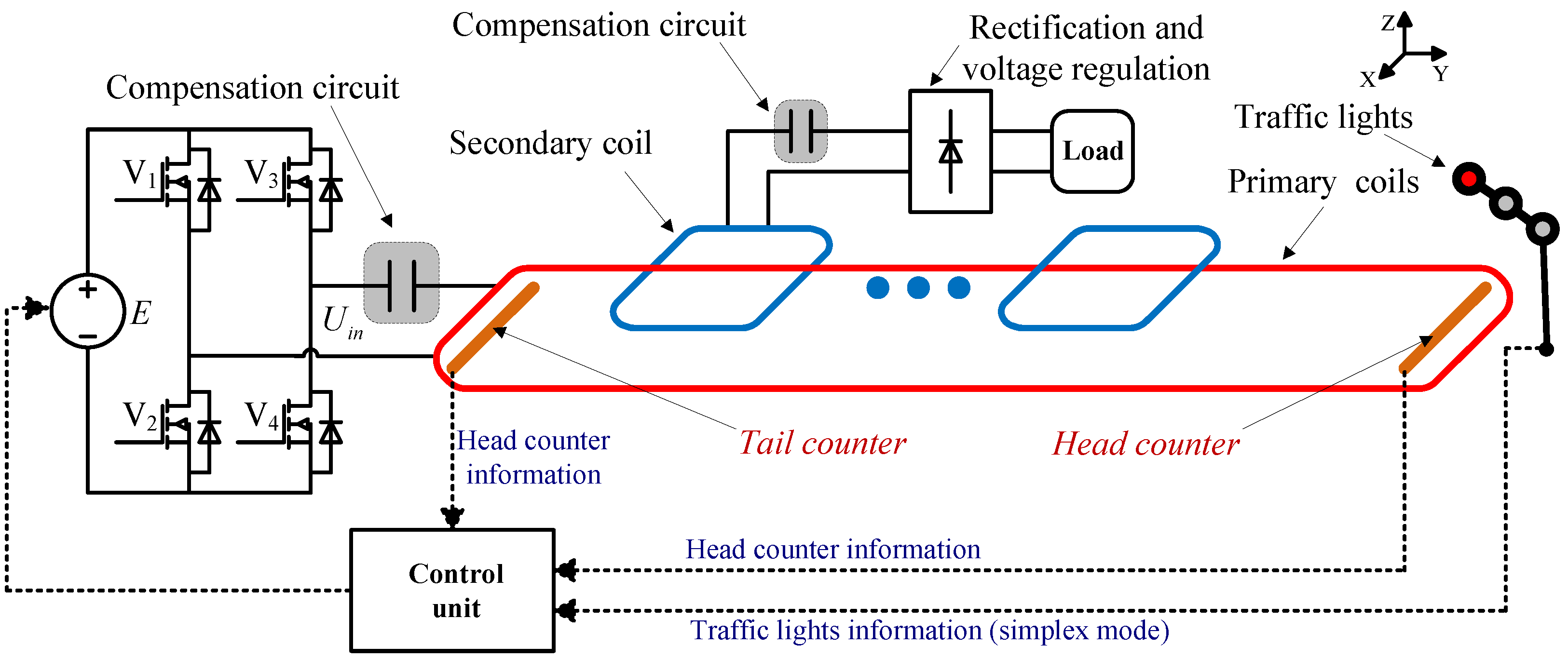
The single long rectangular primary coil is installed under the lane at the traffic lights. When the traffic light is red, the EV can be charged wirelessly and conveniently when the EV is detected in the effective wireless charging area. The principle of the opportunity EV wireless charging system at traffic lights proposed in this paper is shown as
Figure 1.
The primary side of the proposed system consists of a traffic light information unit, EV counter information unit, control unit, high-frequency inverter, and the primary coil with compensation circuit. The secondary side includes the secondary coil with compensation circuit, rectification and voltage regulation unit, and the load. The communication mode of information of traffic lights is one-way communication in order to avoid influences on the traffic light system. The control unit combines the traffic lights information and the counter information, and also controls the DC voltage of the high-frequency inverter. The energy is transferred wirelessly through the electromagnetic coupling between the primary and secondary coils. The structure diagram of the opportunity EV wireless charging system is shown in
Figure 2. In order to solve the issue of low electricity quality, at least two aspects should be dealt with in practical application. Firstly, a front-end power factor corrector (PFC) stage should be installed in front of the rectifier and the high-frequency inverter in order to handle the reactive burden. Secondly, the dc-link capacitor should also be installed between the rectifier and the high-frequency inverter in order to handle the ripple current.
The opportunity EV wireless charging system at traffic lights is a complex system with many issues to be investigated. In order to focus on the power fluctuation caused by the random access loads, theoretical analysis is carried out and a control strategy is proposed under the following hypotheses:
- (i)
The actual implementation of obtaining the information of traffic lights and the detection method of EVs are not mentioned in this paper.
- (ii)
When the traffic light is red and the EV is about to enter the effective wireless charging area, the EV is assumed to need charging and can be wireless charged.
- (iii)
When the traffic light turns green, the whole system turns off. Namely, all EVs quit simultaneously at that time.
- (iv)
The parameters of secondary coils in each EV are identical. The load characteristics are supposed to be identical too. In this paper, the actual load, including rectifier and battery, is simplified as the AC equivalent resistive load, which can be directly connected with the secondary coil. The differences of load characteristics caused by different batteries can be eliminated by using impedance conversion technology. At the preliminary stage of our research, we mainly focus on the wireless charging system for EVs with the same power level. In the future, we will deal with EVs of different power levels in the proposed system.
- (v)
On the one hand, most of the energy is transferred wirelessly through the fundamental square wave from the high-frequency inverter. On the other hand, the harmonics cause slight extra loss in primary side. Since the harmonic components count for a slight part in inverter output voltage, the loss caused by the harmonics is far less than that caused by the fundamental component. So the power source can be assumed to be ideal high-frequency sinusoidal in theoretical analysis.
3. System Modelling and Analysis
The circuit model of the proposed opportunity EV wireless charging system at traffic lights is displayed in
Figure 3. The primary side and the secondary side are compensated with the resonant capacitors.
and
represent the voltage and the internal resistance of the high-frequency power source respectively.
,
, and
represent the resistance, the inductance and the compensation capacitor of the primary coil respectively. The number of loads in system is
.
,
and
denote the resistance, the inductance and the compensation capacitor of the
kth
secondary coil respectively.
is the
kth load.
represents the mutual inductance between the
kth secondary coil and the primary coil.
is the mutual inductance between the
ith
secondary coil and the
jth
secondary coil.
On the basis of Kirchhoff’s voltage law, the model in
Figure 3 is built by
where
is the current of the primary circuit,
is the current of the
kth secondary circuit, and
is the impedance matrix of the system.
The non-diagonal element and . The diagonal elements and represent the impedances of primary circuit and secondary circuits respectively, where and . , and is the working frequency.
Since the distance between two secondary coils is long enough in this system, the mutual inductance between two secondary coils can be ignored, namely,
. According to the hypotheses mentioned above, the inner resistance of every secondary coil is assumed to be
and each load is assumed to be
. The working frequency is set to be the resonant frequency of every circuit, namely,
and
. The impedance matrix, Equation (2), can be simplified as
The current in the primary circuit can be calculated as
The current in the
kth secondary circuit is
After the inner resistance of the power source is ignored, the received power of the
kth load can be expressed as
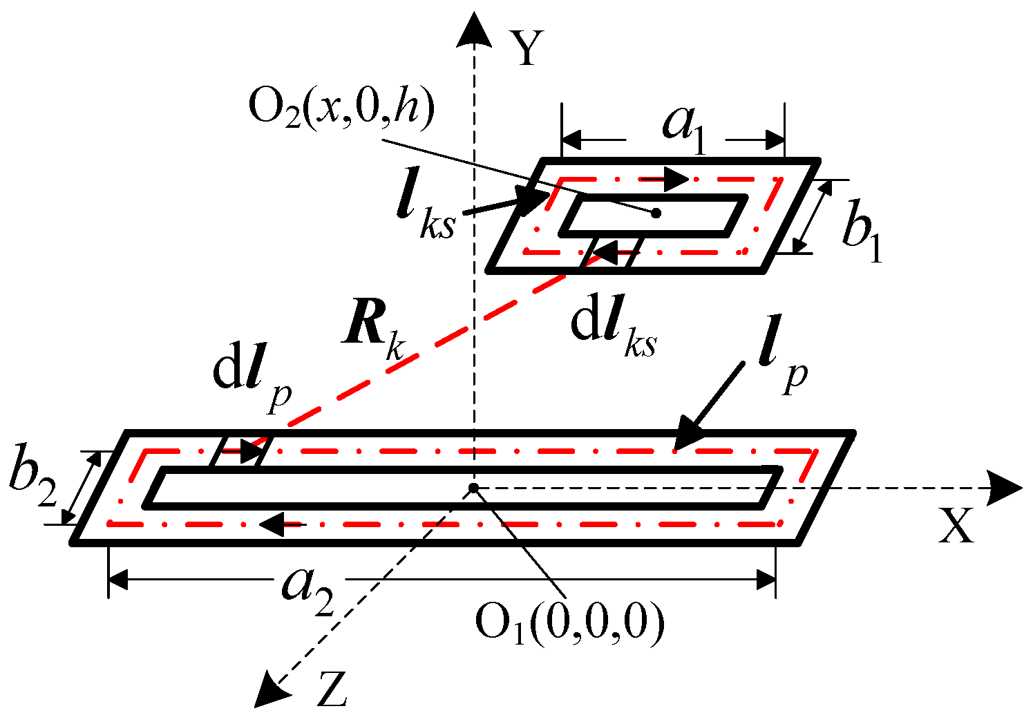
The diagram of mutual inductance calculation is shown in
Figure 4.
and
represent the numbers of turns in primary coil and secondary coil respectively.
is the vacuum permeability and
is the relative permeability.
and
are the current loops in the primary circuit and the
kth secondary circuit respectively.
and
are infinitesimal in the current loops respectively.
is the vector distance between
and
. The central coordinates of the primary coil and secondary coil are O
1 (0, 0, 0) and O
2 (
x, 0,
h) respectively, where
is the abscissa of the secondary coil center and
h is the vertical height.
According to the Neumann formula,
can be calculated as
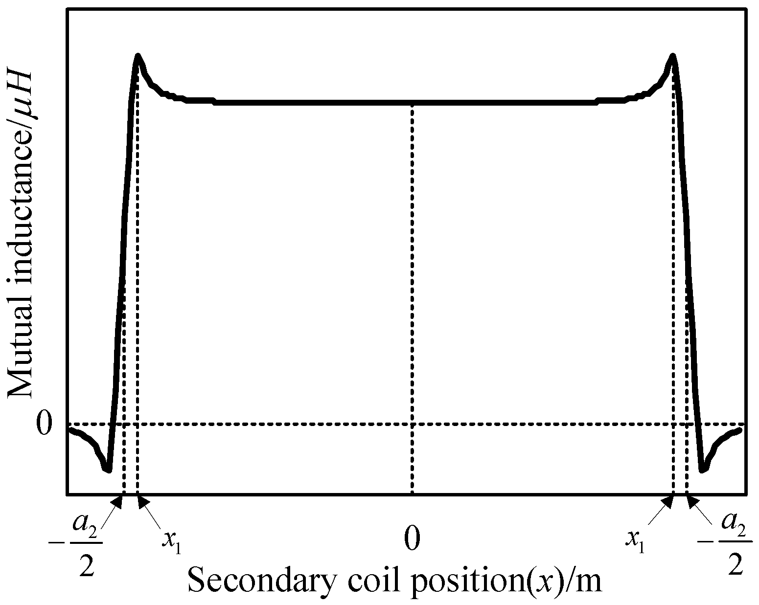
The curve of
versus position variation of the secondary coil can be obtained as shown in
Figure 5.
The effective wireless charging area is the area where the secondary coil can be located right above the primary coil. The lateral misalignment is not taken into account in this paper. As shown in
Figure 5, the effective wireless charging area can be expressed as
, where
is
and
is
. The received power changes little when the EV is in the effective charging area because the
does not change much there. On the other hand, the final stopping place of each EV is uncertain. Hence
(the Root Mean Square of
) is chosen to express the mutual inductance in the effective wireless charging area approximately.
After Equation (8) is written into Equation (6), when the secondary coil is in the effective wireless charging area completely, the received power can be calculated as
If always remains constant, it is difficult for to maintain stability because is randomly changing. In order to reduce adverse effects that the random access of the new load has on the received power of previous loads, a power stabilization strategy, including counting the number of EVs, adjusting the power source voltage and choosing the counting points, is proposed in the following part. The received power of loads will be stabilized and the system’s adaptation to the random access load will be promoted with the application of this strategy.
5. Experimental Verifications
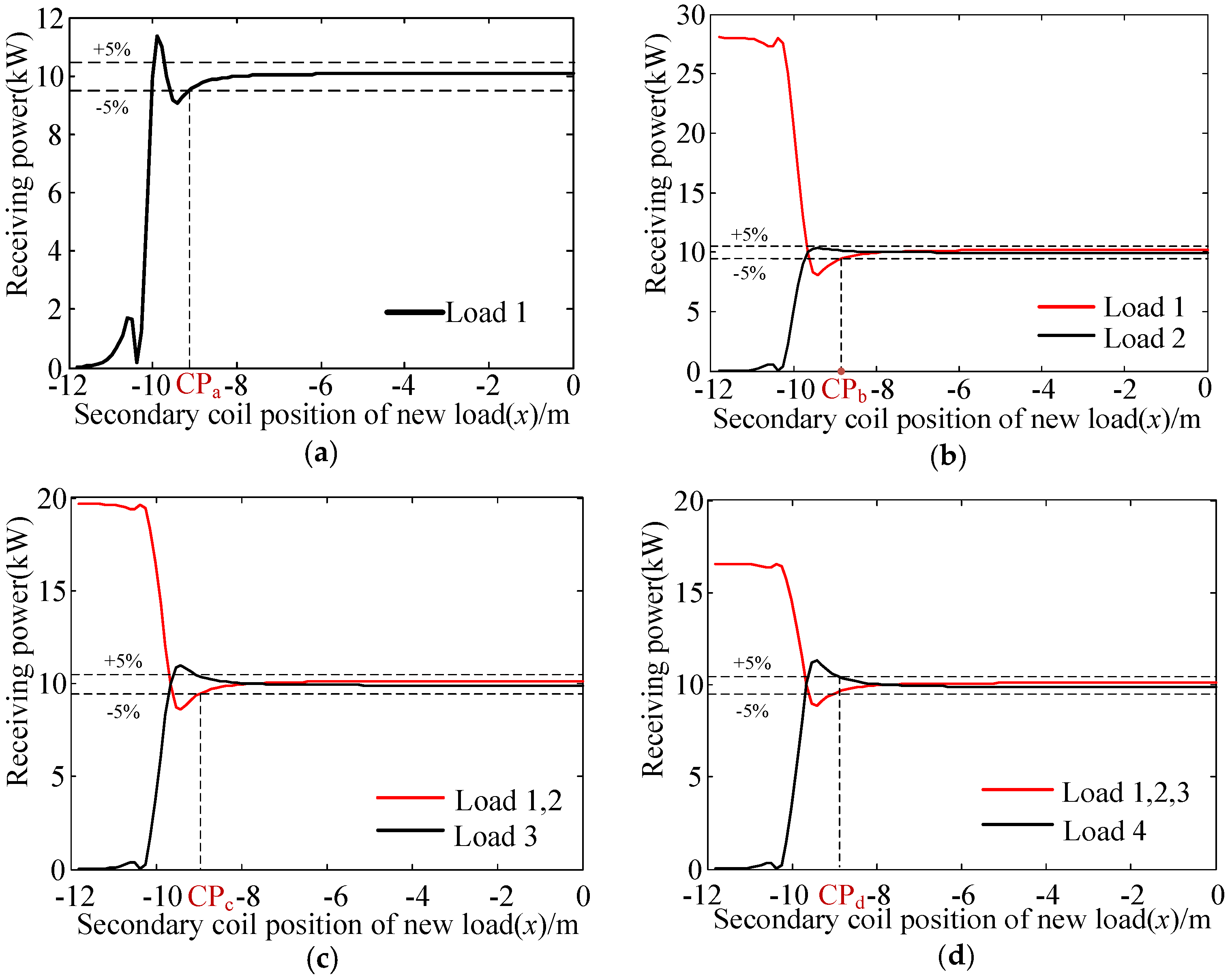
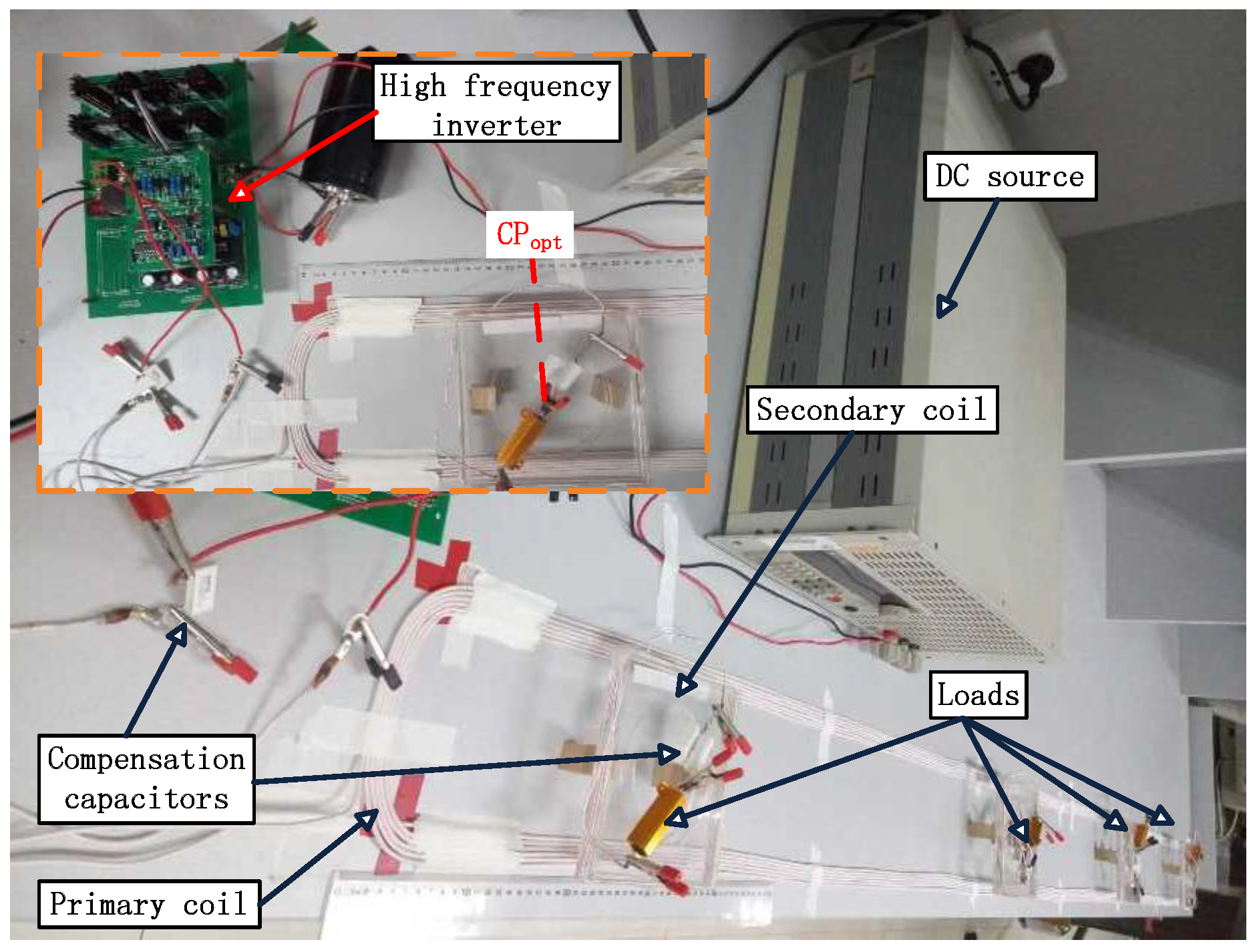
The experimental prototype of an opportunity EV wireless charging system with four loads at most is proposed in
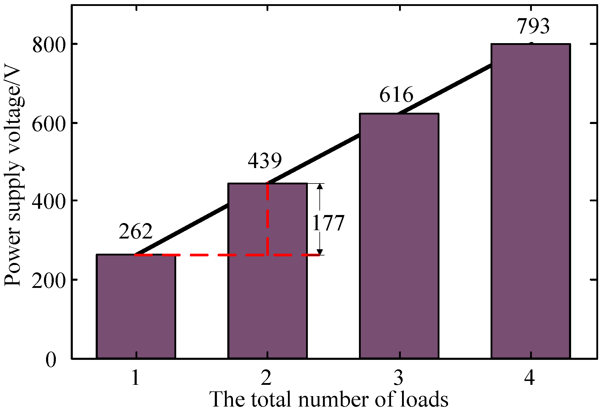
Figure 9. The width and length of the rectangular primary coil are 0.15 m and 3.33 m respectively. The number of the turns is six. The secondary coils are square coils of seven turns and with a side of 0.15 m. The vertical distance between primary side and secondary side is 0.03 m. The inductance, the resistance and the compensation capacitor of the primary coil are 153.1 μH, 0.5 Ω and 22 nF respectively. The inductance, the resistance and the compensation capacitor of the secondary coils are 20.4 μH, 0.1 Ω and 168 nF respectively. Because of the manufacture of the coils and the capacitors with a fixed value, the working frequency is set to 87 kHz. In accordance with the theoretical analysis before, after the numerical simulation method, the power source voltage adjustment strategy is clarified as follows. The voltage is 5.0 V when only one load is detected and it increases by
= 3.5 V when a new load accesses. Furthermore, the tail counter position is determined as CP
opt = −1.45 m based on 5% bounded domain of received power. The head counter is omitted due to the symmetrical installment of the two counters.
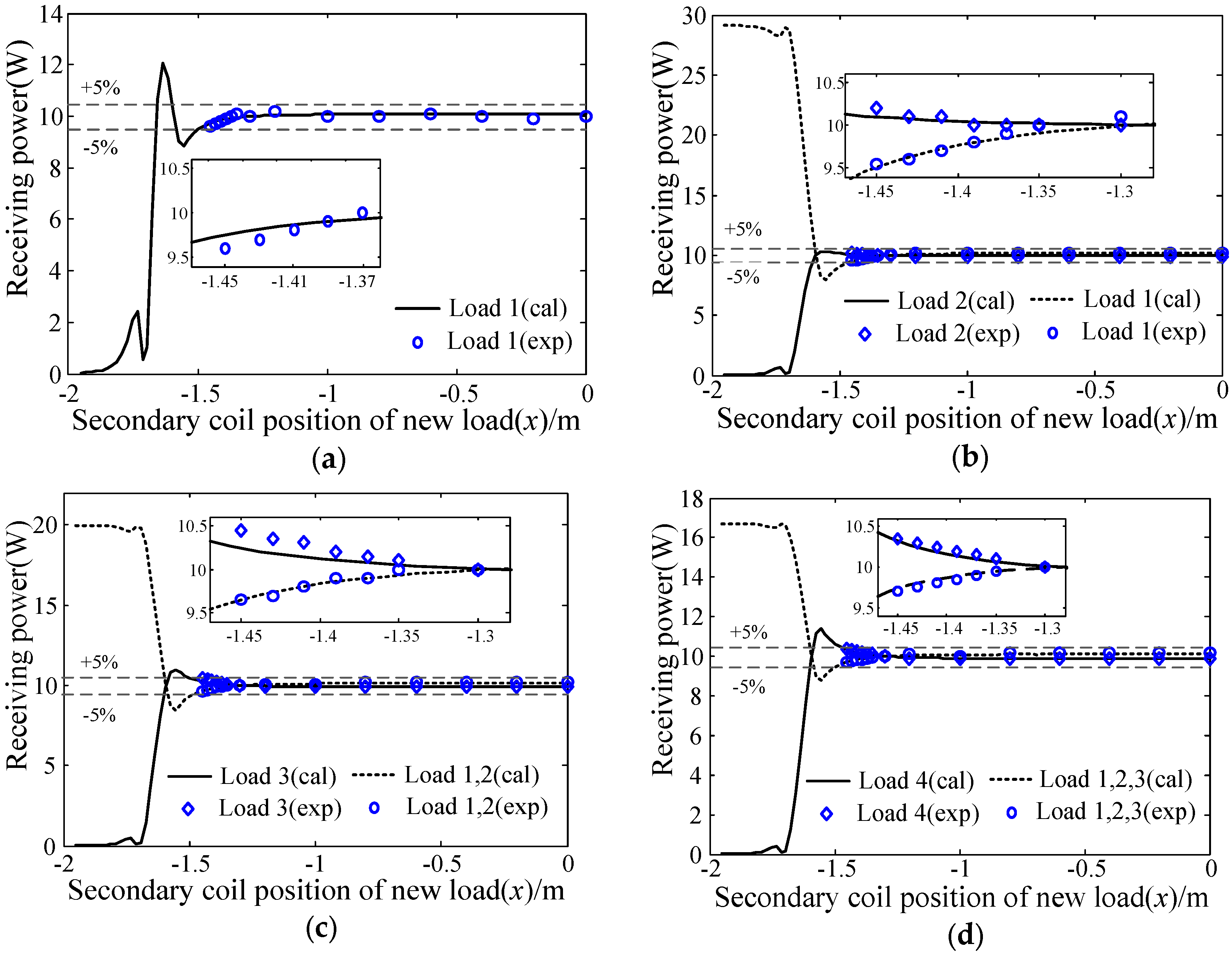
In the experimental process, when the first load is located at the tail counter, the power source voltage is adjusted to
= 5.0 V approximately. After changing the position of the first load and measuring the received power of it, the curve of received power versus position variation of the first load is shown in
Figure 10a. When a new load is located at the tail counter, the voltage of power source increases by 3.5 V, namely,
= 8.5 V,
= 12.0 V and
= 15.5 V. The other curves of received power versus position variation of the new access load are shown in
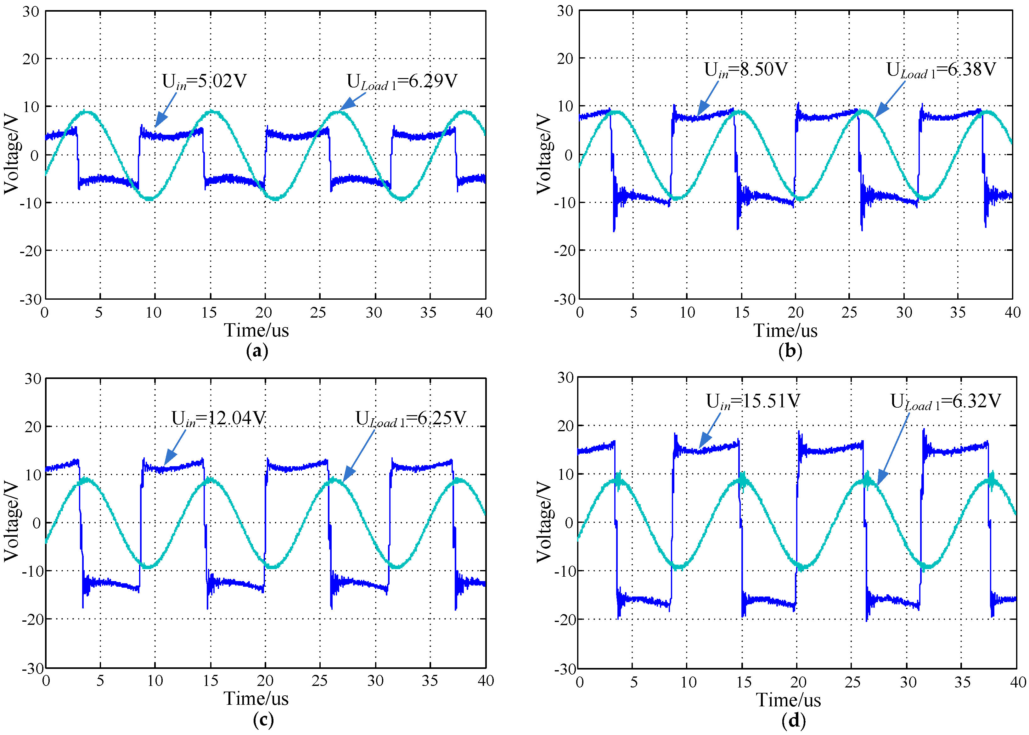
Figure 10. According to the experimental results, the received power is around 10 W with fluctuation constrained in 5%. The voltage waveforms of the power source and the voltage waveforms of loads in systems with different load numbers when systems are at a steady state are shown in
Figure 11. The voltages are measured with voltage probes (Tektronix TPP0500B, Beaverton, OR, USA).
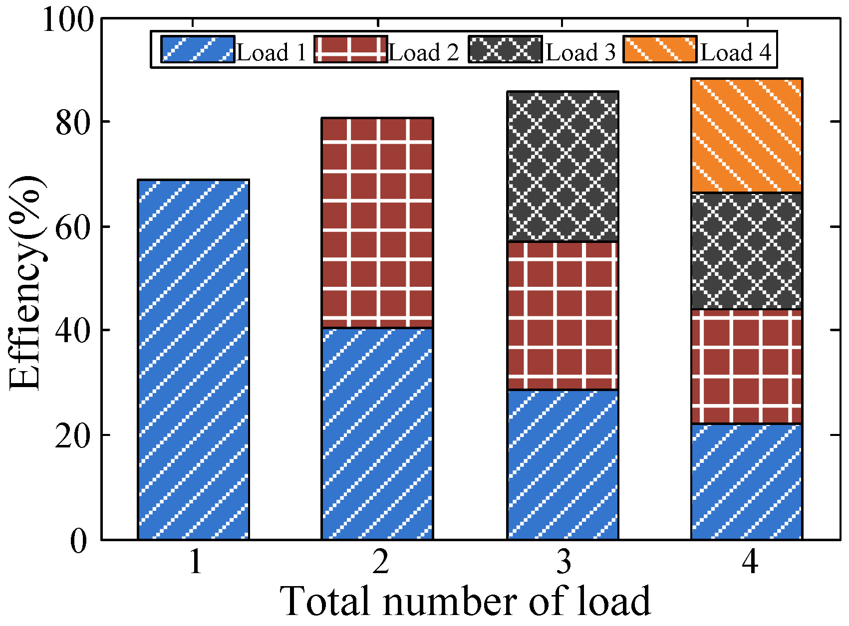
The efficiency stack graph of systems with different load numbers when systems are at a steady state is shown in
Figure 12. The efficiency increases with the increased load number.
The experimental prototype with low power rating is proposed to verify the theoretical research. The proposed power stabilization strategy is not influenced by the power rate. With the application of the power stabilization strategy proposed in this paper, the power source voltage is adjusted with the changing load number. The received power of loads is stabilized around 10 W and the power fluctuations are limited within 5%. Experimental results demonstrate the correctness of previous theoretical study.


 and
and 


