Article

Plasma Glow Discharge as a Tool for Surface Modification of Catalytic Solid Oxides: A Case Study of La0.6Sr0.4Co0.2Fe0.8O3−δ Perovskite

1
National Key Laboratory for Precision Hot Processing of Metals, School of Materials Science and Engineering, Harbin Institute of Technology, Harbin 150001, China
2
CAS Key Laboratory of Materials for Energy Conversion, Department of Materials Science and Engineering, University of Science and Technology of China, Hefei 230026, China
3
Center for Innovative Fuel Cell and Battery Technologies, School of Materials Science and Engineering, Georgia Institute of Technology, Atlanta, GA 30332, USA
*
Authors to whom correspondence should be addressed.
Energies 2016, 9(10), 786; https://doi.org/10.3390/en9100786
Submission received: 12 July 2016 / Revised: 23 September 2016 / Accepted: 23 September 2016 / Published: 28 September 2016
(This article belongs to the Special Issue Solid Oxide Fuel Cells)

Abstract

:
Performance of solid oxide fuel cells (SOFCs) is hindered by the sluggish catalytic kinetics on the surfaces of cathode materials. It has recently been reported that improved electrochemical activity of perovskite oxides can be obtained with the cations or the oxides of some metallic elements at the surface. Here, we used a cost-effective plasma glow charge method as a generic tool to deposit nano-size metallic particles onto the surface of SOFC materials. Ni nano-scale patterns were successfully coated on the La0.6Sr0.4Co0.2Fe0.8O3−δ (LSCF) surface. The microstructure could be well controlled. The kinetics of oxygen exchange on the modified LSCF surface was promoted significantly, confirmed by electrical conductivity relaxation (ECR) measurement.

1. Introduction

Solid oxide fuel cells (SOFCs) have been studied as efficient solutions to the generation of electrical energy from traditional chemical energy stored in hydrogen or hydrocarbon fuels [1]. One of the most challenging issues is that the performance at intermediate temperatures (600–800 °C) is generally limited by the sluggish kinetics of catalytic reactions on the native surface of electrode materials [2,3,4,5]. Two normal ways to enhance electrode performance have been developed. One is the use of new SOFC materials with high catalytic activities and conducting properties. The other is the fabrication of nano-structured electrodes with an extremely high amount of electrochemically active sites [6]. Chemical infiltration has been considered an effective tool to make nano-scale microstructures while permitting the use of more combinations of conductors and catalysts [7,8,9,10,11]. However, the infiltration method has not been developed maturely for industrial applications, most likely due to the following reasons. The morphology is not easy to control due to the difficulties in controlling the processing factors and the wettability between the infiltrate solution and the substrate material. The infiltration–calcination process is usually repeated several times to achieve better modification, which is quite time-consuming (typically several days) [12,13,14]. Recently, Ruiz-Trejo et al. [15] prepared Ni-infiltrated Zr0.92Y0.08O1.96 (YSZ) anodes using Tollens’ reaction followed by an electro-deposition procedure, which is a fast and low energy consumption alternative to infiltration. In addition to the porous electrodes, the idealized structures, such as patterned micro-electrodes and thin-film coatings are very important to study the fundamental properties of surfaces, interfaces, and materials. In this regard, chemical infiltration is ineffective, as compared to some other methods, e.g., chemical vapor deposition [16], pulsed laser deposition [17], and atomic layer deposition [18,19]. However, these methods are expensive and usually limited to laboratory use.
In this work, we use a plasma glow discharge method for the surface modification of SOFC materials. This method is widely used for the modification of steels and alloy surfaces in industries to enhance surface hardness and corrosion properties by introducing plasma nitrogen and carbon into the surface layer. We found that the chemical elements of the hollow metal cathode can also be sputtered off and then deposited onto the specimen’s surface [20]. Inspired by this finding, we expect this method is feasible as a tool for surface modification of SOFC materials. Recently, it has been reported that the surface exchange of (La,Sr)CoO3 (LSC) could be improved by introducing less reducible cations, such as Nb5+, Ti4+, Zr4+, Hf4+, and Al3+ at the surface [21]. The same concept is suggested to be applicable to other state-of-the-art perovskite catalysts, such as La0.6Sr0.4Co0.2Fe0.8O3−δ (LSCF). In addition to introducing less reducible cations, coating transition metal oxides is another effective way. Hong et al. [22] reported that the surface exchange coefficient of LSCF with CuO nanoparticles coating on its surface is several times higher than that of the bare LSCF. In this work, Ni nanoparticles were deposited successfully onto the surface of LSCF bar specimens using the plasma glow discharge method. It was shown that the surface morphology is controllable by this method, and the kinetics of oxygen surface exchange is improved. We believe that this method is also applicable to coating other metallic nanoparticles onto many SOFC materials, such as anode materials and some cathode materials that are stable under the low-oxidizing or even reducing discharge atmosphere. In fact, this method is capable of coating metallic nanoparticles onto the internal surface of a porous YSZ electrolyte skeleton. Therefore, it is feasible to make nanostructured SOFCs using a porous YSZ scaffold/YSZ electrolyte/porous LSCF triple-layer green cell through a single step plasma glow discharge process, while maintaining (actually increasing) the catalytic activity of LSCF, which will constitute further study.

2. Results and Discussion

Figure 1 shows the scanning electron microscopy (SEM) micrographs of the LSCF surface after Ni deposition at 800 °C held for 0 min. The “0 min” denotes that the furnace was cooled down once the designed temperature was achieved. Thus, the growth of the microstructures may have been at an early stage. Although the microstructure was not uniform after this process, the nucleation and growth of Ni particles could be captured. Figure 1a shows a representative microstructure with four specific micro-regions, showing different stages of deposition of Ni particles. In micro-region A, Ni particles were deposited randomly onto the LSCF bare surface, showing the very beginning stage of the Ni deposition. It is shown in Figure 1b that the particle size was 50–100 nm. The Ni nanoparticles accumulated (Figure 1c) and eventually formed a thin film, which is, however, not dense (Figure 1d). Then, the Ni nanoparticles began to coarsen to some extent (Figure 1e). It is shown in Figure 1a–e that the deposition seems to have had no preference on the LSCF grain surface or the grain boundary. Figure 1f shows the cross-sectional microstructure, showing that the film thickness was about 200 nm.

2.1. Effects of Depositing Time and Temperature

Figure 2 shows the surface morphologies of the bare LSCF surface and the ones after depositing at 800 °C for 15, 30, and 60 min. The Ni particles were columnar shaped, and the size of the Ni nanoparticles was apparently unchanged after the various depositing times. The columnar particles preferred to grow perpendicularly to the LSCF substrate. The film was porous and tended to be more porous with the increase in depositing time. This result demonstrates that the present method is capable of preparing a porous medium consisting of columnar nanoparticles, suggesting a high internal surface area and fast transport kinetics. The pore size was 100–200 nm, which is too small for gas transport. However, the high internal surface area indicates a high catalytic activity. In fact, the nano-sized structures are usually used as the electrochemically active layer of SOFCs, typically with a ~10-μm thickness.
Figure 3 shows the SEM micrographs of the LSCF sample after the treatment of depositing nickel at different temperatures for 60 min. The morphology of the particles were different at different temperatures. At 650 °C, the particles were hemispherical with a diameter of 50 nm. At 800 °C, the particles were columnar with a length of 1 μm and a diameter of 50 nm. At 950 °C, the particles were hemispherical, but with a bigger diameter of 100 nm. These results show that the shape and size of particles are controllable by tailoring depositing time and temperature. However, the mechanisms are not yet clearly identified. We suppose that the combining effects of sputtering and depositing are crucial. The columnar shape of the Ni nanoparticles may be attributed to the sputtering process perpendicular to the LSCF surface. The hemispherical shape at a low temperature may be attributed to the limited driving force for coarsening. Since the sputtering strength was dominated mainly by the cathode voltage and plasma composition, it was apparently unchanged by increasing temperature. Thus, at a high temperature, the depositing process dominates. Therefore, the Ni nanoparticles thermodynamically tend to coarsen, forming spherical shape particles.

2.2. Promotion in Catalytic Activity

The electrical conductivity relaxation (ECR) measurements were conducted at 800 °C, 750 °C, and 700 °C. As shown in Figure 4, the relaxation time was shortened significantly at the various temperatures by the Ni-coating. In what follows, the surface exchange (k) and chemical bulk diffusion (D) coefficients are resolved for the results at 750 °C. For the bare LSCF bar, the ECR curve is governed by both k and D [23]. Thus, the experimental data for the bare LSCF bar can be fitted by the following equation:
σ t σ 0 σ σ 0 = 1 i = 1 m = 1 n = 1 2 L x 2 exp ( β i 2 D t / x 2 ) β i 2 ( β i 2 + L x 2 + L x ) × 2 L y 2 exp ( γ m 2 D t / y 2 ) γ m 2 ( γ m 2 + L y 2 + L y ) × 2 L z 2 exp ( δ n 2 D t / z 2 ) δ n 2 ( δ n 2 + L z 2 + L z )
where:
L x = x k D = β i tan β i ; L y = y k D = γ m tan γ m ; L z = z k D = δ n tan δ n
Therein, D denotes the chemical bulk diffusion coefficient; k denotes the oxygen surface exchange coefficient, which is a lumped parameter considering the coupled surface exchange and diffusion within the thin surface layer; x, y, and z are the dimensions of the bar; β, γ, and δ are the positive roots of Equation (2). The fitting results in Figure 5a show that the calculated D and k are consistent with the literature data [23]. However, for the LSCF bar coated with Ni particles by 800 °C × 60 min treatment, the ECR curve is insensitive to the value of k, as shown in Figure 5b. In other words, the incorporation of oxygen into the LSCF bar was not limited by the surface exchange. Therefore, as shown in Figure 5b, the relaxation time was only 800 s, as compared to the 8000 s of the bare LSCF bar. Thus, the ECR curve can be fitted by the following equation only considering chemical bulk diffusion, while k is considered as infinity:
σ t σ 0 σ σ 0 = 1 i = 1 m = 1 n = 1 8 exp ( ( 2 i 1 ) 2 π 2 D t / 4 x 2 ) ( 2 i 1 ) 2 π 2 × 8 exp ( ( 2 m 1 ) 2 π 2 D t / 4 y 2 ) ( 2 m 1 ) 2 π 2 × 8 exp ( ( 2 n 1 ) 2 π 2 D t / 4 z 2 ) ( 2 n 1 ) 2 π 2
The fitted value of D is 8.4 × 10⁻⁶ cm2/s, consistent with the value of the bare LSCF bar.
Figure 6a shows the X-ray diffraction (XRD) patterns of the LSCF bar treated at 800 °C for 1 h and the sample after the ECR measurement. For the as-prepared sample, Fe-Ni metal, NiO, NiFe2O4, and the LSCF phase are detected. There is a small amount of NiO formed after the process. Therefore, the atmosphere is not strongly reducing. This may be the reason that LSCF is chemically stable after the process, although there may be some change in its non-stoichiometry of oxygen. For the sample after the ECR measurement, NiO and NiFe2O4 are still detectable, while the Fe-Ni metal is not apparent, which is attributed to the oxidation of Ni. Figure 6b shows the Gibbs energy of the various phases, cited from the data base of HSC Chemistry software (Outokumpu Research Oy, Pori, Finland), showing the thermodynamic preference of the formation of NiO and NiFe2O4. In addition to the increase in surface area by the formation of nanoparticles, the promotion in surface exchange kinetics is also derived from the NiFe2O4 phase, which is a candidate of SOFC cathode material [24]. Rao et al. [25] reported that the electric and ionic conductivities of NiFe2O4, for example, 0.1 S/cm and 0.005 S/cm, respectively, at 700 °C, were much lower than that of LSCF. However, the area specific resistance of the NiFe2O4 electrode was comparable to that of the LSCF electrodes, and several times lower than that of (La,Sr)MnO3 electrodes. Although the corresponding k and D for a dense NiFe2O4 are not available in the literature, it is rational to suppose that NiFe2O4 may exhibit a higher surface exchange coefficient over LSCF, similar to the findings proposed by Ding et al. who promoted the surface exchange of LSCF by coating a thin layer of (Ls,Sr)MnO3 film (whose ionic conductivity is lower but surface exchange coefficient is higher as compared with LSCF) on its surface [26]. These results suggest a potential method for preparing LSCF cathodes under low-oxidizing atmospheres while promoting the surface exchange kinetics.

3. Materials and Methods

LSCF was prepared by a combustion method. The LSCF bar specimens with dimensions of 30 mm × 5 mm × 1 mm were prepared by a sintering process. The details can be found elsewhere [27]. A homemade plasma glow discharge instrument was used to coat Ni nano-particles onto the surface of LSCF bar specimens. The LSCF bar was fixed in the chamber, surrounded by a Ni hollow cathode. The furnace chamber was evacuated to 60 Pa by a rotary pump in the Ar atmosphere. Then, an impulse direct current with 650 V was used to trigger glow discharge. The temperature rose with time, and was controlled at 650 °C, 800 °C, and 950 °C via adjusting the duty cycle of the voltage. The holding time at each temperature was 0 min, 15 min, 30 min, and 60 min. The furnace was then cooled down slowly in the furnace chamber under the protection of Ar.
The phase structure of the surface was characterized by XRD (X’PERT PRO MPD, PANalytical B.V., Almelo, The Netherlands) with Cu-Kα radiation (λ = 0.15406 nm). The 2θ ranged from 20° to 90°. The scanned velocity was 4°/min. The XRD peaks were indexed using Jade 6.0 software (Materials Data Inc., Livermore, CA, USA) with JCPDS and ICSD data base. The morphology of the samples was observed via SEM, (S-4700, Hitachi, Tokyo, Japan). The ECR method [28] was used to measure the conductivity relaxation curve. The oxygen exchange coefficient and chemical bulk diffusion coefficient were calculated through fitting the analytic equations to the relaxation curve.

4. Conclusions

The Ni nano-scale patterns were deposited on the LSCF bar using a plasma glow discharge process under an Ar atmosphere. The effects of treatment temperature and time on the surface morphology were studied, demonstrating that the morphology of deposited particles could be controlled by tailoring the temperature and time. The ECR relaxation time at 750 °C of the LSCF bar treated at 800 °C for 1 h is one order of magnitude lower than that of the bare LSCF bar. The promotion in surface exchange kinetics is derived from the increase in surface area and the formation of the NiFe2O4 phase.

Acknowledgments

We gratefully acknowledge the financial support from Natural Science Foundation of China (51402066, 21673062, and 51371070), the Fundamental Research Funds for the Central Universities (Grant No. HIT. NSRIF. 20167), and the China Postdoctoral Science Foundation funded project (2015M571410, LBH-Z15061, and 2016T90282).

Author Contributions

Yanxiang Zhang and Mufu Yan conceived and designed the experiments; Jingbo Ma and Mei Li performed the experiments; All the authors analyzed the data; Mufu Yan and Changrong Xia contributed reagents, materials, and analysis tools; Yanxiang Zhang and Jingbo Ma wrote the paper.

Conflicts of Interest

The authors declare no conflict of interest.

References

  1. Arnab, C.; Chandra, H.; Arora, A. Application of solid oxide fuel cell technology for power generation—A review. Renew. Sustain. Energy Rev. 2013, 20, 430–442. [Google Scholar]
  2. Babaei, A.; Zhang, L.; Liu, E.; Jiang, S.P. Performance and stability of La0.8Sr0.2MnO3 cathode promoted with palladium based catalysts in solid oxide fuel cells. J. Alloy. Compd. 2011, 509, 4781–4787. [Google Scholar] [CrossRef]
  3. Kiebach, R.; Knöfel, C.; Bozza, F.; Klemensø, T.; Chatzichristodoulou, C. Infiltration of ionic-, electronic- and mixed-conducting nano particles into La0.75Sr0.25MnO3–Y0.16Zr0.84O2 cathodes—A comparative study of performance enhancement and stability at different temperatures. J. Power Sources 2013, 228, 170–177. [Google Scholar] [CrossRef]
  4. Zou, J.; Park, J.; Yoon, H.; Sammes, N.M.; Chung, J. Effects of transition metal ion dopants on the performance of Ca2.9Bi0.1Co4O9−δ cathode. J. Alloy. Compd. 2013, 558, 188–194. [Google Scholar] [CrossRef]
  5. Gan, Y.; Qin, Q.; Chen, S.; Wang, Y.; Dong, D.; Xie, K.; Wu, Y. Composite cathode La0.4Sr0.4TiO3−δ–Ce0.8Sm0.2O2−δ impregnated with Ni for high-temperature steam electrolysis. J. Power Sources 2014, 245, 245–255. [Google Scholar] [CrossRef]
  6. Liu, Y.; Wang, F.; Chi, B.; Pu, J.; Li, J.; Jiang, S.P. A stability study of impregnated LSCF–GDC composite cathodes of solid oxide fuel cells. J. Alloy. Compd. 2013, 578, 37–43. [Google Scholar] [CrossRef]
  7. Zhou, Y.; Meng, X.; Ye, X.; Li, J.; Wang, S.; Zhan, Z.L. Metal-supported solid oxide fuel cells with impregnated SrFe0.75Mo0.25O3 cathodes. J. Power Sources 2014, 247, 556–561. [Google Scholar] [CrossRef]
  8. Chen, J.; Liang, F.; Yan, D.; Pu, J.; Chi, B.; Jiang, S.P.; Li, J. Performance of large-scale anode-supported solid oxide fuel cells with impregnated La0.6Sr0.4Co0.2Fe0.8O3−δ+Y2O3 stabilized ZrO2 composite cathodes. J. Power Sources 2010, 195, 5201–5205. [Google Scholar] [CrossRef]
  9. Jung, S.; Lu, C.; He, H.; Ahn, K.; Gorte, R.J.; Vohs, J.M. Influence of composition and Cu impregnation method on the performance of Cu/CeO2/YSZ SOFC anodes. J. Power Sources 2006, 154, 42–50. [Google Scholar] [CrossRef]
  10. Vohs, J.M.; Gorte, R.J. High-performance SOFC cathodes prepared by infiltration. Adv. Mater. 2009, 21, 943–956. [Google Scholar] [CrossRef]
  11. Jiang, S.P. Nanoscale and nano-structured electrodes of solid oxide fuel cells by infiltration: Advances and challenges. Int. J. Hydrog. Energy 2012, 37, 449–470. [Google Scholar] [CrossRef]
  12. Jiang, Z.; Xia, C.; Chen, F. Nano-structured composite cathodes for intermediate-temperature solid oxide fuel cells via an infiltration/impregnation technique. Electrochim. Acta 2010, 55, 3595–3605. [Google Scholar] [CrossRef]
  13. Liu, Y.; Chi, B.; Pu, J.; Li, J. Performance degradation of impregnated La0.6Sr0.4Co0.2Fe0.8O3+Y2O3 stabilized ZrO2 composite cathodes of intermediate temperature solid oxide fuel cells. Int. J. Hydrog. Energy 2012, 37, 4388–4393. [Google Scholar] [CrossRef]
  14. Shah, M.; Voorhees, P.W.; Barnett, S.A. Time-dependent performance changes in LSCF-infiltrated SOFC cathodes: The role of nano-particle coarsening. Solid State Ion. 2011, 187, 64–67. [Google Scholar] [CrossRef]
  15. Ruiz-Trejo, E.; Atkinson, A.; Brandon, N.P. Metallizing porous scaffolds as an alternative fabrication method for solid oxide fuel cell anodes. J. Power Sources 2015, 280, 81–89. [Google Scholar] [CrossRef]
  16. Kim, J.; Jang, D.; Kim, M.; Choi, H.; Shim, J. Nano-granulization of gadolinia-doped ceria electrolyte surface by aerosol-assisted chemical vapor deposition for low-temperature solid oxide fuel cells. J. Power Sources 2016, 301, 72–77. [Google Scholar] [CrossRef]
  17. Ju, Y.; Jun, A.; Inoishi, A.; Ida, S.; Lim, T.; Kim, G.; Ishihara, T. Growth of thin-film layered perovskite cathodes by pulsed laser deposition and their electrochemical studies in IT-SOFCs. J. Electrochem. Soc. 2014, 161, F698–F702. [Google Scholar] [CrossRef]
  18. Gong, Y.H.; Patel, R.; Liang, X.; Palacio, D.; Song, X.; Goodenough, J.B.; Huang, K. Atomic layer deposition functionalized composite SOFC cathode La0.6Sr0.4Fe0.8Co0.2O3−δ-Gd0.2Ce0.8O1.9: Enhanced long-term stability. Chem. Mater. 2013, 25, 4224–4231. [Google Scholar] [CrossRef]
  19. Choi, H.; Bae, K.; Jang, D.; Park, S.; Han, G.; Shim, J. Surface modification of La0.6Sr0.4Co0.2Fe0.8O3−δ cathode by atomic layer deposition of La0.6Sr0.4CoO3−δ for high-performance solid oxide fuel cells. ECS Trans. 2015, 68, 729–733. [Google Scholar] [CrossRef]
  20. Cong, T.; Yan, M.; Liu, R. Multiphase films bearing Ti2AlN by pulse plasma hollow cathode nitriding. Surf. Eng. 2013, 29, 336–341. [Google Scholar] [CrossRef]
  21. Tsvetkov, N.; Lu, Q.; Sun, L.; Crumlin, E.; Yildiz, B. Improved chemical and electrochemical stability of perovskite oxides with less reducible cations at the surface. Nat. Mater. 2016, 15, 1010–1016. [Google Scholar] [CrossRef] [PubMed]
  22. Hong, T.; Brinkman, K.; Xia, C. Copper oxide as a synergistic catalyst for the oxygen reduction reaction on La0.6Sr0.4Co0.2Fe0.8O3−δ perovskite structured electrocatalyst. J. Power Sources 2016, 329, 281–289. [Google Scholar] [CrossRef]
  23. Bouwmeester, H.; Den Otter, M.; Boukamp, B.A. Oxygen transport in La0.6Sr0.4Co1-yFeyO3−δ. J. Solid State Electrochem. 2004, 8, 599–605. [Google Scholar] [CrossRef]
  24. Smith, F.; Um, W.; Taylor, C.; Kim, D.; Schweiger, M.; Kruger, A. Computational investigation of technetium(IV) incorporation into inverse spinels: Magnetite (Fe3O4) and trevorite (NiFe2O4). Environ. Sci. Technol. 2016, 50, 5216–5224. [Google Scholar] [CrossRef] [PubMed]
  25. Rao, Y.; Wang, Z.; Chen, L.; Wu, R.; Peng, R.; Lu, Y. Structural, electrical, and electrochemical properties of cobalt-doped NiFe2O4 as a potential cathode material for solid oxide fuel cells. Int. J. Hydrog. Energy 2013, 38, 14329–14336. [Google Scholar] [CrossRef]
  26. Ding, D.; Li, X.; Lai, Y.; Gerdes, K.; Liu, M. Enhancing SOFC cathode performance by surface modification through infiltration. Energy Environ. Sci. 2014, 7, 552–575. [Google Scholar] [CrossRef]
  27. Li, M.; Ren, Y.; Zhu, Z.; Zhu, S.; Chen, F.; Zhang, Y.; Xia, C. La0.4Bi0.4Sr0.2FeO3−δ as cobalt-free cathode for intermediate-temperature solid oxide fuel cell. Electrochim. Acta 2016, 191, 651–660. [Google Scholar] [CrossRef]
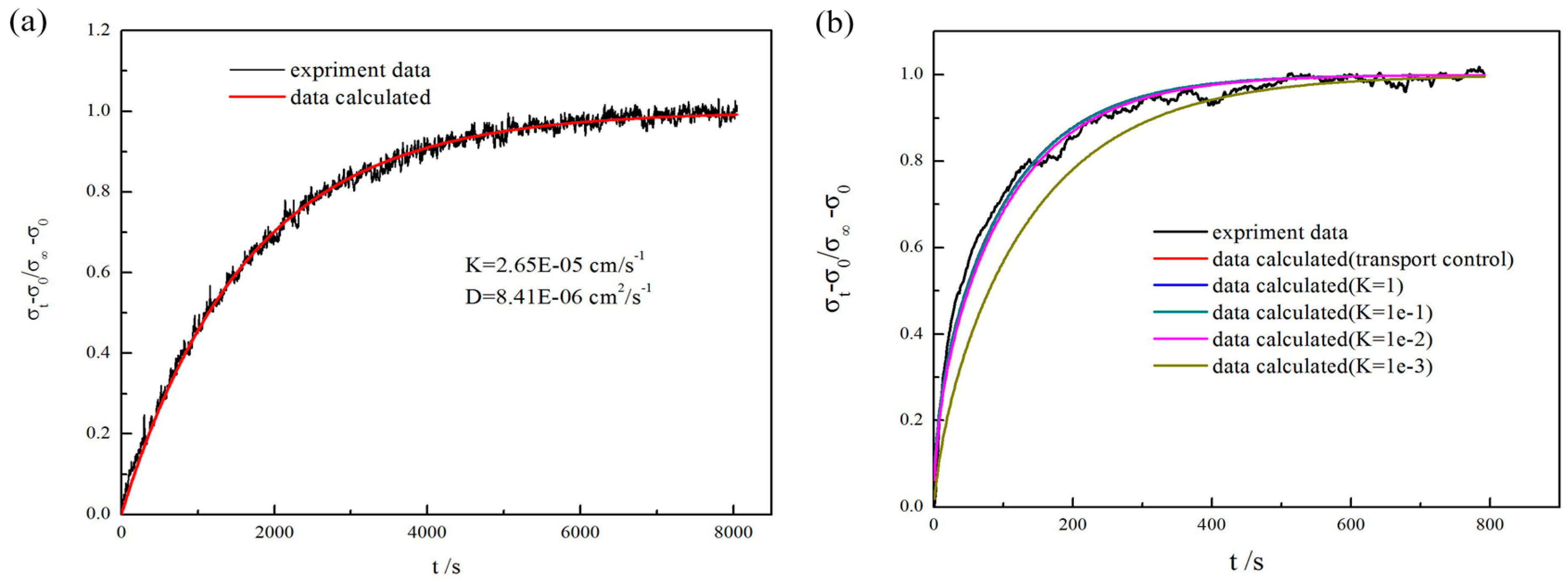
  28. Hu, B.; Xia, C. Factors influencing the measured surface reaction kinetics parameters. Asia-Pac. J. Chem. Eng. 2016, 11, 327–337. [Google Scholar] [CrossRef]
Figure 1. Scanning electron microscopy (SEM) micrographs of La0.6Sr0.4Co0.2Fe0.8O3−δ (LSCF) sample after the treatment of depositing nickel at 800 °C for 0 h: (a) macro-scope morphology; (be) magnified picture of the parts A–D; and (f) cross profile of the sample.
Energies 09 00786 g001
Figure 2. SEM micrographs of LSCF samples: (a) the fresh sample; and 800 °C for (b) 15 min; (c) 30 min; and (d) 60 min.
Energies 09 00786 g002
Figure 3. SEM micrographs of LSCF sample after the treatment of depositing nickel at different temperatures for 1-h: (a) 650 °C; (b) 800 °C; (c) 950 °C; and (d) magnified picture of (c).
Energies 09 00786 g003
Figure 4. The electric conductivities relaxation curves for both the uncoated (black) and Ni-coated (red) samples at (a) 800 °C; (b) 750 °C; and (c) 700 °C.
Energies 09 00786 g004
Figure 5. Experimental data and fitting curves of conductivity change profiles (750 °C) as a function of relaxation time for (a) the pure LSCF bar and (b) the LSCF bar with Ni particles by 800 °C × 60 min.
Energies 09 00786 g005
Figure 6. (a) X-ray diffraction (XRD) patterns of the LSCF bar as prepared (1 h at 800 °C) and the one after the electrical conductivity relaxation (ECR) test; and the Gibbs energy of the various phases cited from the HSC Chemistry software (b).
Energies 09 00786 g006

