1. Introduction
Nowadays, with its considerable potential for practical applications, wireless power transfer (WPT) technology is gaining much attention from researchers. WPT system can deliver electrical energy from a power source to a load via varying magnetic fields, and the transmission power level ranges from a few milliwatts to several hundred kilowatts.
There are many benefits that make this technique particularly attractive, such as the electrical and mechanical isolation, the decrease in maintenance costs, and the potential for use in harsh environments. Therefore, WPT can be used for wireless battery charging for implantable biomedical devices [
1,
2,
3,
4] and portable electronics [
5,
6,
7]. Moreover, even electric vehicles (or roadway-powered electric vehicles) can be wirelessly powered [
8,
9,
10,
11].
In terms of practical applications, most of the circuits and systems require constant source supply for stable operation; therefore, a relatively constant output in WPT system is desired regardless of load variations.
In two-coil WPT systems, there have been many efforts [
1,
2,
12,
13,
14,
15,
16,
17] to regulate the output voltage under varying couplings and loads. [
12,
13,
14,
15] exhibited relatively constant output voltage under coupling variations. However, the variation of output voltage is relatively high, and the distance range for constant output is limited. In addition, the effect of load variations on output voltage is not discussed. In [
1], using the transformer model, the voltage transfer function was obtained; an operating frequency corresponding to a particular coupling coefficient could be found, for which the voltage transfer function was irrelevant to load. In [
2], the output voltage was insensitive to loading variations if the operating frequency was adjusted according to coupling variations, and a parallel-resonant class-D oscillator transmitter was developed to track this optimal operating frequency. In [
16], a design and optimization method was proposed to achieve a better overall efficiency and good output voltage controllability in a WPT system. For both the secondary series- and parallel-compensations in two-coil WPT, by calculating the partial derivative of the voltage gain with respect to the load, [
17] analyzed the frequencies that could provide a constant voltage gain despite load variations.
However, in some charging applications, a load-independent output current is more desirable. For example, a constant output current is preferred for driving an LED to have stable luminance, or multistep constant current of a charging profile to charge a battery pack for electric vehicles. An extra current regulator stage, which results in extra power loss, is needed if the WPT system outputs as a voltage source. In [
18], operating frequencies for maximal efficiency and load-independent output current in two-coil WPT are explored. Moreover, the dual circuits of the secondary series- and parallel-compensated WPT have been studied. It is found that the trend of the output current of a series-compensated (parallel-compensated) WPT system studied in [
18] replicates the trend of the output voltage of a parallel-compensated (series-compensated) WPT system in [
17].
With increasing transmission distance in two-coil WPT, the performance of the two-coil WPT deteriorates. Adding a repeating coil, which receives the magnetic field from the transmitter and then relays the magnetic field to the receiver, enhances inductive coupling at longer distances. However, a detailed analysis of load-independent output current in such a three-coil WPT system is still lacking in previous studies.
In this study, a three-coil WPT system is investigated. To determine the operating frequency for the particular coupling coefficient—in this case, the output current remains constant despite changes in the load—we first substitute the coupling coefficients, the quality factor, and the resonant frequency of each coil into the expression of the root-mean-square (RMS) of the output current, and then the frequencies that can provide load-independent output current in a three-coil WPT are found for the first time. To verify the results of this analysis, theoretical calculations and experiments are conducted.
2. Modeling
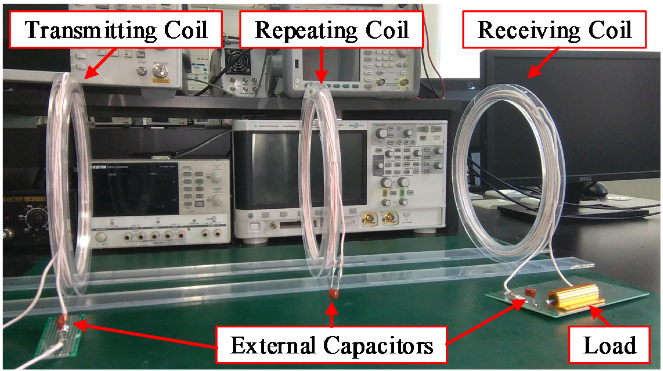
Figure 1 presents a photograph of a three-coil WPT system. The AC voltage source supplies power for the transmitting coil (TX). Through the inductive coupling between the coils, current can be induced in the receiving coil (RX), providing power for the load [
19,
20].
Figure 1.
Photograph of a three-coil WPT system.
Figure 1.
Photograph of a three-coil WPT system.
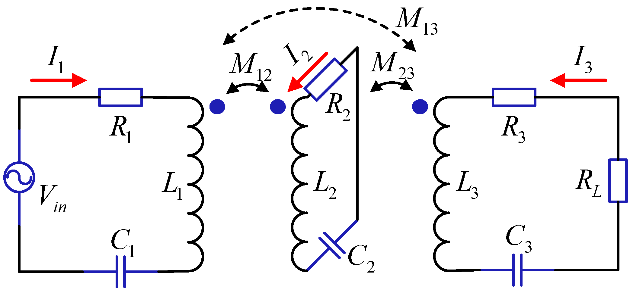
As shown in
Figure 2, the WPT system can be modeled by circuit theory [
21,
22]. A constant AC voltage source
is used for the power supply, and
is the loading resistor. The TX, the repeating coil, and the RX are represented as a resistor-inductor-capacitor (RLC) circuit, and the inductive coupling between the coils is described by the mutual inductance. The parameters of the TX are denoted with subscript 1, the repeating coil with subscript 2, and the RX with subscript 3.
is the inductance of coil
(
), whose equivalent resistance is
, and external capacitor
is added to form a series-tuned topology.
and
are the mutual inductances between each two adjacent coils, and
is the mutual inductance between the TX and the RX.
Figure 2.
Equivalent circuit of the three-coil WPT system.
Figure 2.
Equivalent circuit of the three-coil WPT system.
3. Frequency for Load-Independent Output Current in Three-Coil WPT
The Kirchhoff’s voltage law (KVL) equations of the equivalent circuit in
Figure 2 are:
where
is the current in the coil
(
),
is the voltage source, and
is the operating frequency.
In this study, bold letters are used to represent the phasors, and italic letters denote real numbers or RMS values of the phasors. For example, is a current phasor, and is the RMS value of . For the given three-coil WPT system, the equivalent resistances of the coils are small enough to be omitted. For simplicity, the cross-coupling is neglected in comparison to the coupling between adjacent coils and .
The expression of the output current
can be obtained by solving Equation (1). To facilitate the analysis, six factors are introduced: the coupling coefficients
and
, the quality factor
, the resonant frequency
(
) of the coil
. These factors are, respectively, defined as:
By substituting Equation (2) into the expression of
, the RMS of
can be derived by:
From Equation (3), it can be readily observed that if:
then the output current in Equation (3) can be rewritten as:
which is insensitive to
. Due to the fact that
is inversely proportional to
,
in Equation (5) is insensitive to
. This load-independent output current is a very desirable feature in three-coil WPT system. This guarantees constant output current when the load changes without using control circuit.
By solving Equation (4), we can obtain the frequencies for load-independent output current in three-coil WPT. Because
holds, and the discriminant (
i.e.,
) in Equation (4) is positive, according to Vieta’s formulas, the bi-quadratic Equation (4) has two positive roots:
where the smaller one is
and the larger one is
.
Specifically, when the resonant frequencies of the coils are identical, that is,
, substituting
into Equation (6), the frequencies for load-independent output current in a three-coil WPT in Equation (6) can be reduced as:
The expressions of the RMS of the currents in the TX, repeating coil, and RX (
i.e.,
,
, and
) can be obtained by solving Equation (1). Thus, the transfer efficiency
in a three-coil WPT system is defined as the ratio of the power dissipation in the load and the total power supplied by the source [
23,
24,
25]:
The output power
in three-coil WPT system is calculated by:
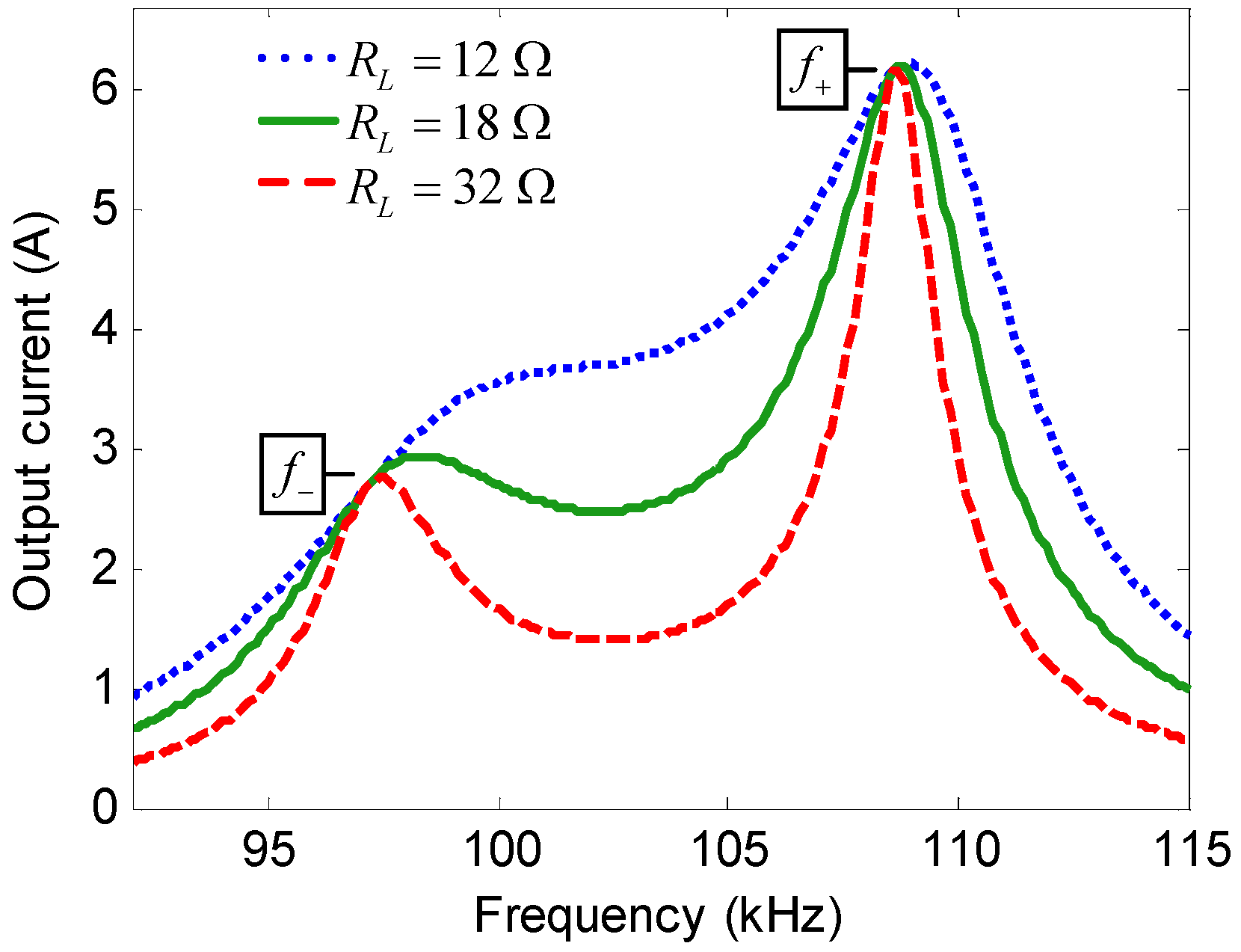
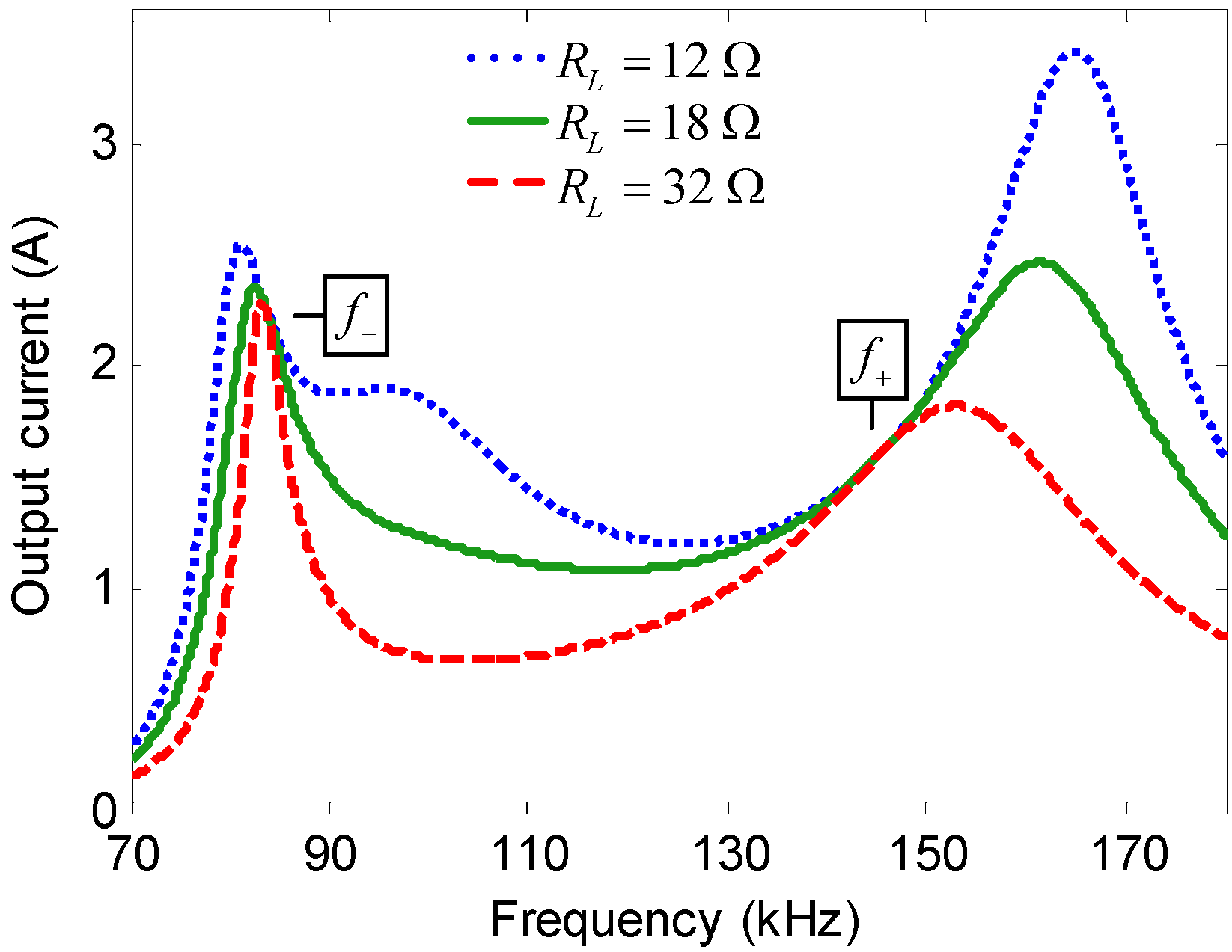
Figure 3 and
Figure 4 show how the calculated output current varies with the operating frequency under three loading conditions in a three-coil WPT system with the parameters listed in
Table 1. The coupling coefficients shown in
Figure 3 are
and
, and that in
Figure 4 are
and
.
Table 1.
Parameters of the experimental setup.
Table 1.
Parameters of the experimental setup.
| Symbol | Note | Value |
|---|
| RMS source voltage | 30 V |
| , , | Resonant frequency of coil 1, 2, 3 | 105 kHz, 100 kHz, 95 kHz |
| , , | Inductance of coil 1, 2, 3 | 58.91 uH, 37.25 uH, 50.12 uH |
| , , | Capacitance of coil 1, 2, 3 | 39 nF, 68 nF, 56 nF |
| , , | Resistance of coil 1, 2, 3 | 0.50 Ω, 0.39 Ω, 0.46 Ω |
| Load resistance | 12 Ω, 18 Ω, 32 Ω |
Figure 3.
Calculated output current versus frequency in a three-coil WPT when and .
Figure 3.
Calculated output current versus frequency in a three-coil WPT when and .
Figure 4.
Calculated output current versus frequency in a three-coil WPT when and .
Figure 4.
Calculated output current versus frequency in a three-coil WPT when and .
As presented in
Figure 3 and
Figure 4, for the given coupling coefficients
and
, there are two operating frequencies at which
is irrelevant to
. In
Figure 3,
and
; in
Figure 4,
and
.
4. Experiments
To verify the above analysis for a three-coil WPT, an experimental setup is implemented, and a set of experiments are performed. Three polypropylene capacitor with the capacitance value 39 nF, 56 nF, and 68 nF are used as the external capacitors. The three-coil WPT system is composed of three circular coils with a radius of 100 mm. These coils are fabricated with Litz wire, and the radius of the Litz wire used in the TX, the repeating coil, and the RX are 1.3 mm, 1.3 mm, and 1.0 mm, respectively. The turn number of the Litz wire used in the TX, the repeating coil, and the RX are 10, 8, and 9, respectively. The inductance of each coil can be measured by an LCR meter.
Figure 1 displays the photograph of the experimental setup, whose parameters are listed in
Table 1. Standard sinusoidal signals generated by a signal generator are amplified by a power amplifier and fed to the transmitting coil of the three-coil WPT system.
For two coaxial circular coils, the mutual inductance can be calculated using Equation (10) [
25,
26]
where
,
and
are complete elliptic integrals of the first and second kind, respectively, and the values of
and
can be obtained by Sidhu’s method, as elucidated in [
27];
is the permeability of vacuum,
and
are the number of turns of the two coils,
and
are the radius of coil-1 and coil-2, respectively, and
is the distance between the two coils.
The inductances of the coils are measured by an LCR meter, and the mutual inductance between the coils is calculated by Equation (10); thus, the coupling coefficients can be calculated by Equation (2).
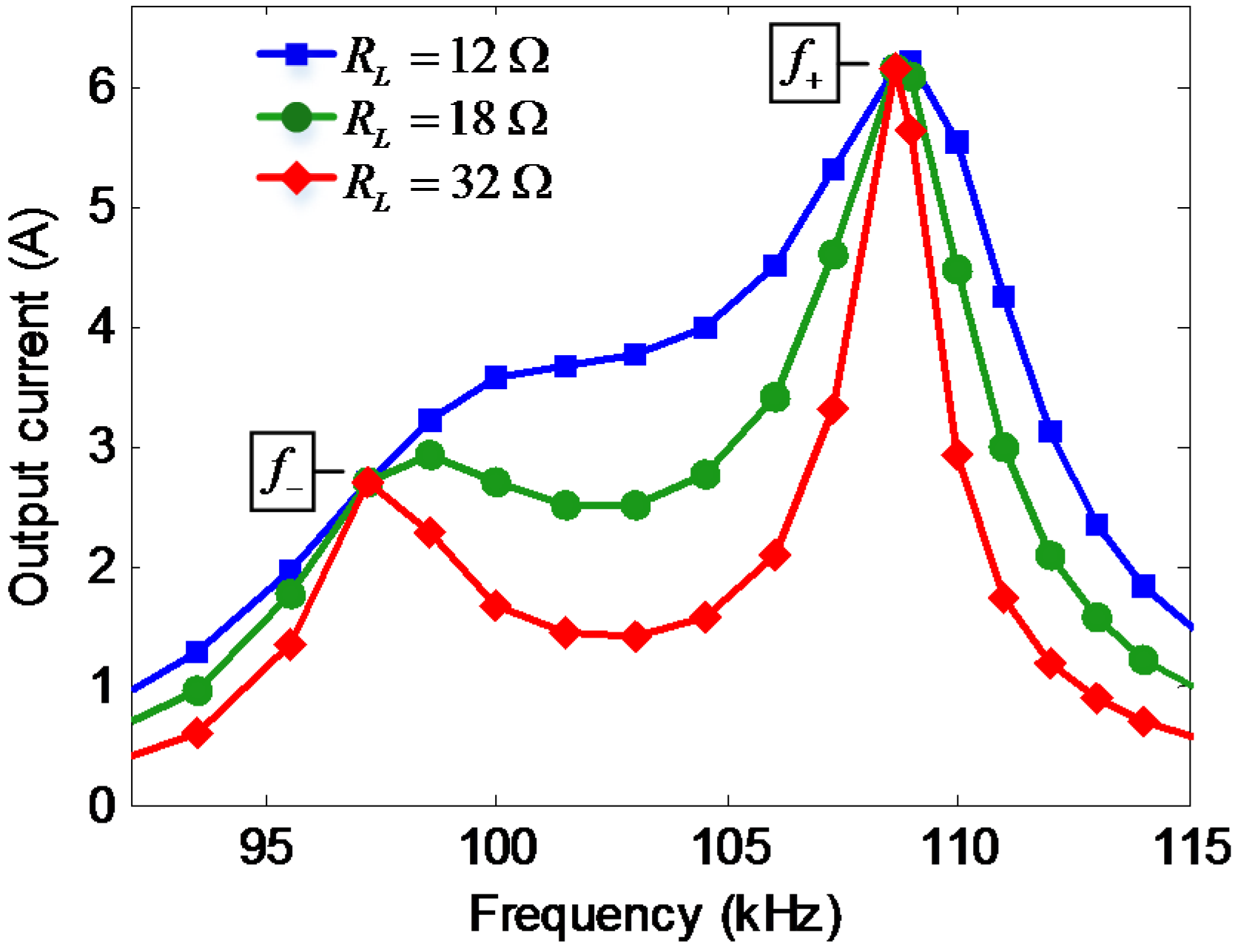
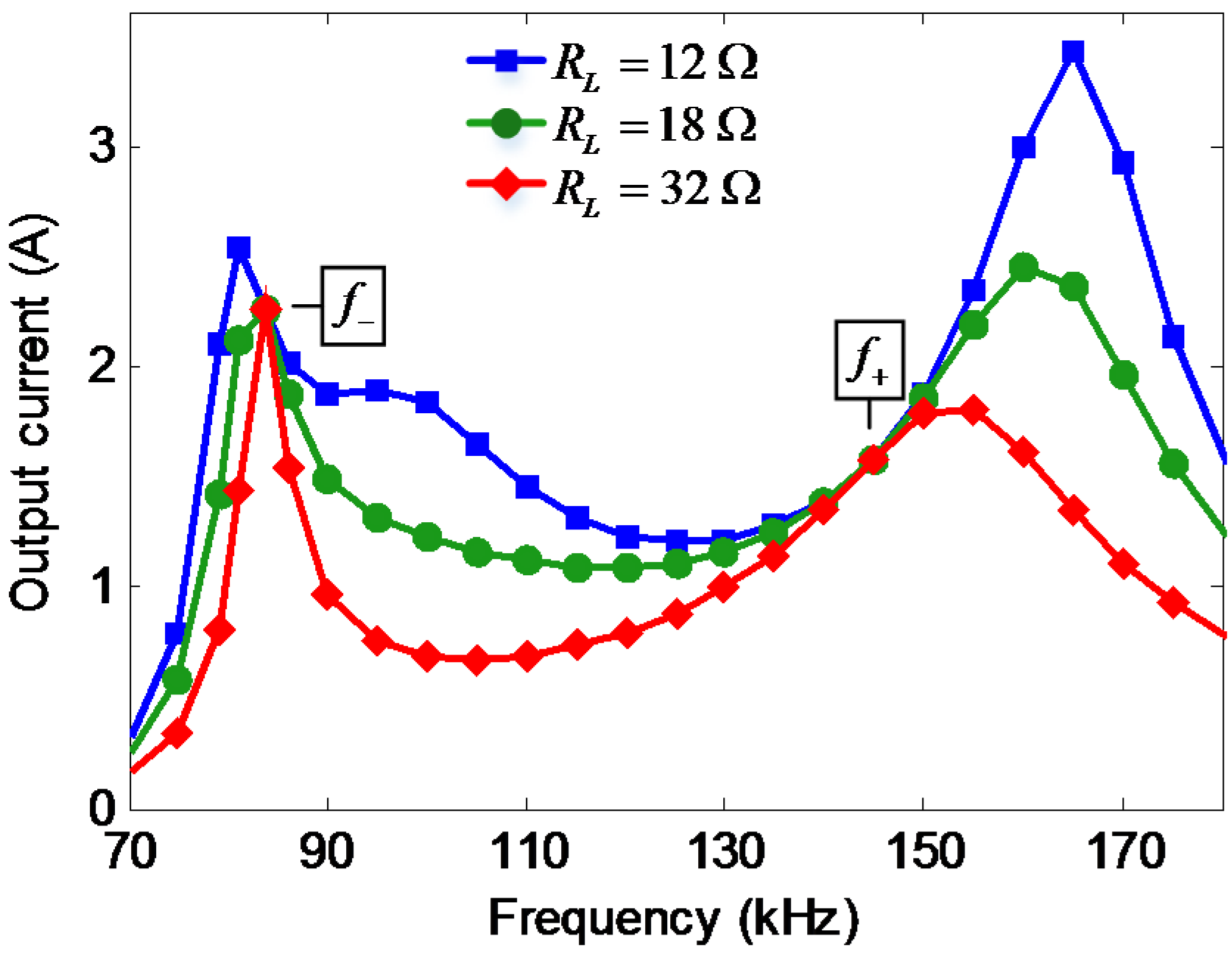
Figure 5 and
Figure 6 show the measured output current
versus the operating frequency under three loading conditions in a three-coil WPT.
Figure 5.
Measured output current versus frequency in a three-coil WPT when and .
Figure 5.
Measured output current versus frequency in a three-coil WPT when and .
Figure 6.
Measured output current versus frequency in a three-coil WPT when and .
Figure 6.
Measured output current versus frequency in a three-coil WPT when and .
As shown in
Figure 5, when
and
, there are two operating frequencies,
i.e.,
and
, at which
is insensitive to
; these findings are consistent with the calculated results in
Figure 3.
In
Figure 6, when
and
, the frequencies for load-independent output current are
and
, which agree with the calculated results in
Figure 4.
Upon comparing the trend of the output current in
Figure 5 and
Figure 6 with that in
Figure 3 and
Figure 4, respectively, the measured results confirm the calculated results.
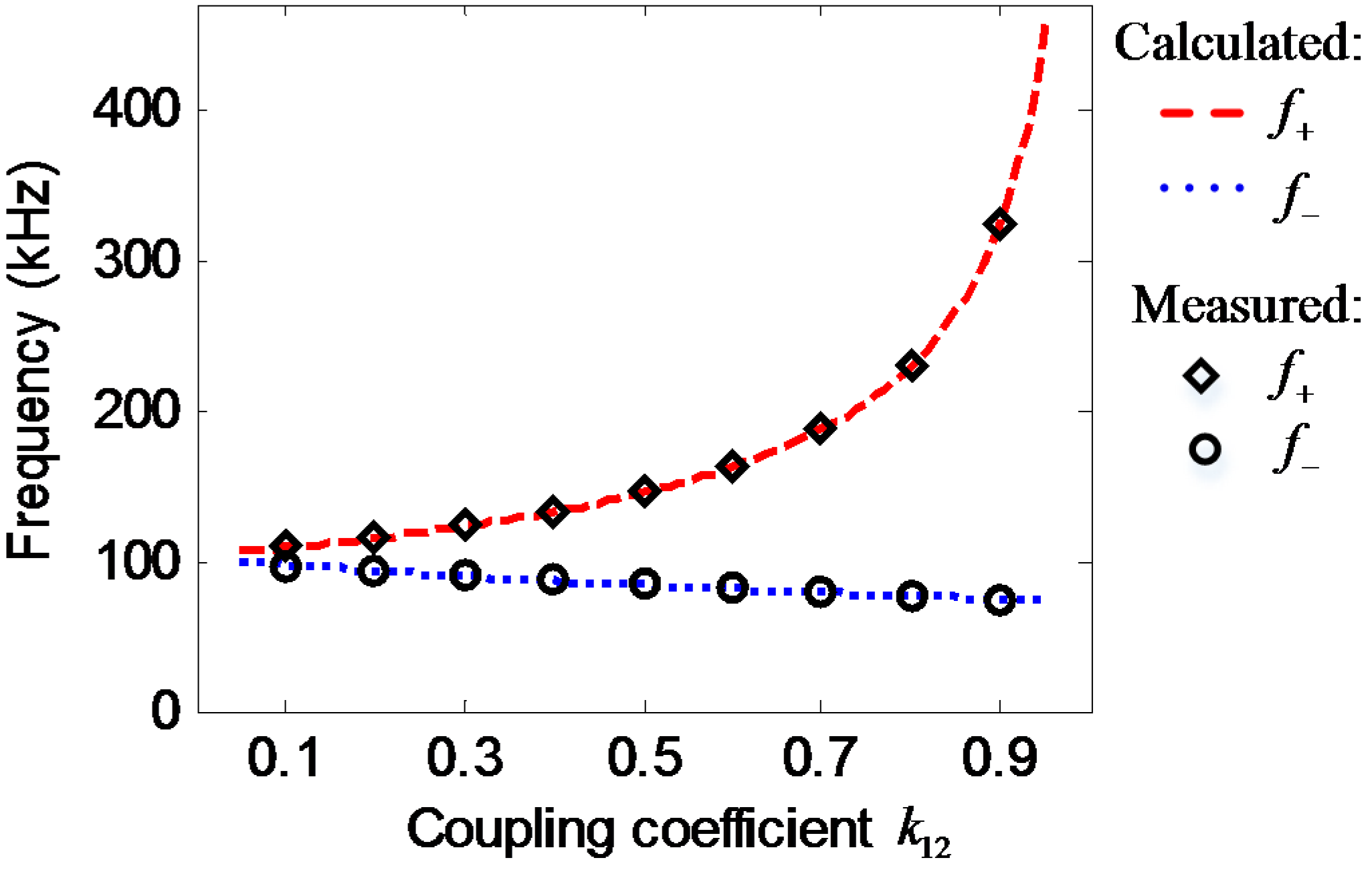
Furthermore, Equation (6) demonstrates that the frequency for load-independent output current is a function of the coupling coefficient and irrelevant to , that is, when is given, the frequencies for load-independent output current in a three-coil WPT are determined.
Figure 7 presents the calculated and measured frequencies for load-independent output current
versus the coupling coefficient
in a three-coil WPT. The dotted line and dashed line are the calculated values of
and
, respectively. The points are measured data: the circles and diamonds denote
and
, respectively. The calculated and measured results are in good agreement, which validates the conclusion reached in
Section 3.
Figure 7.
Calculated and measured frequencies for load-independent output current versus coupling coefficient in a three-coil WPT.
Figure 7.
Calculated and measured frequencies for load-independent output current versus coupling coefficient in a three-coil WPT.
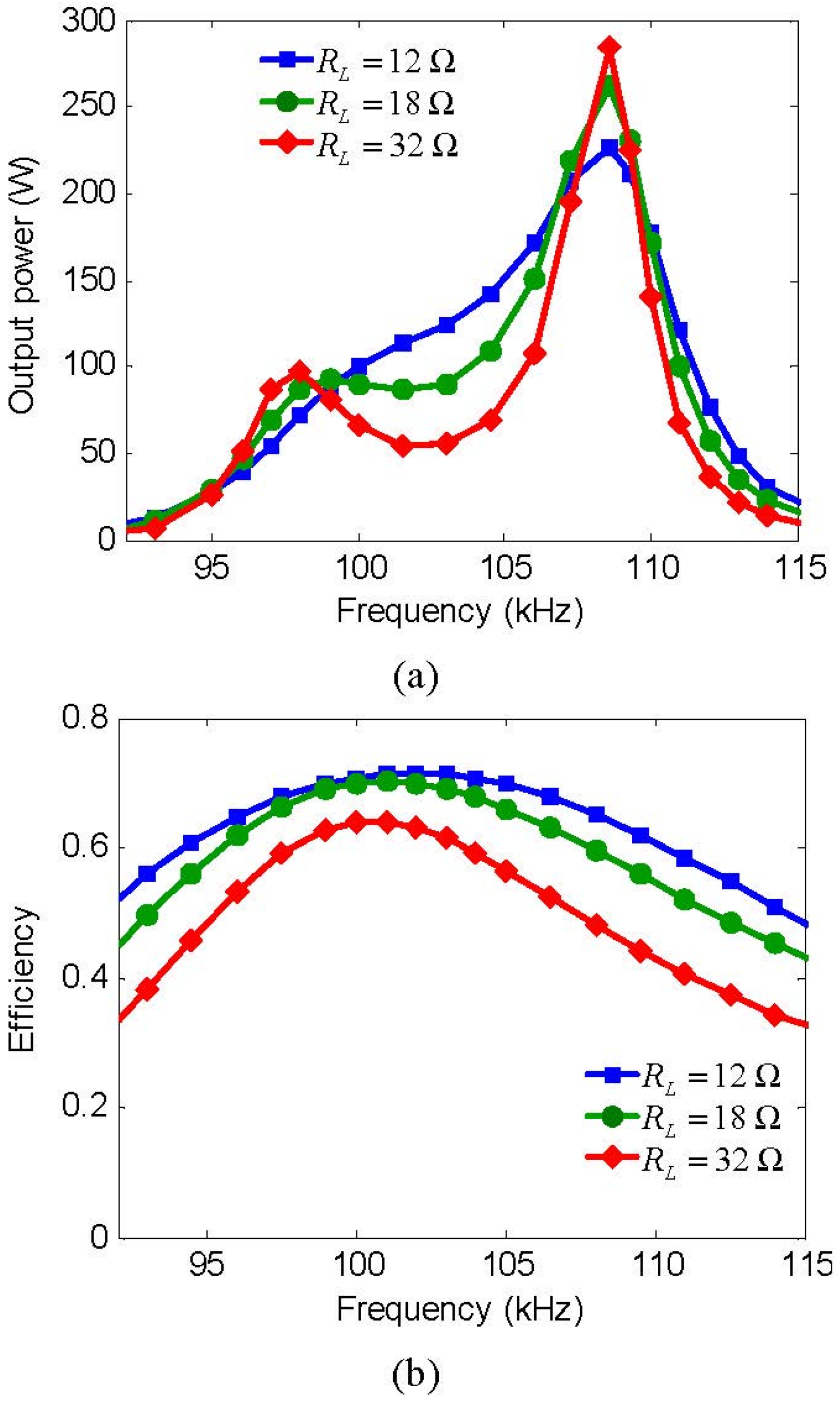
When
and
, the measured results of output power and transfer efficiency
versus frequency in a three-coil WPT system are displayed in
Figure 8a,b, respectively. When
and
,
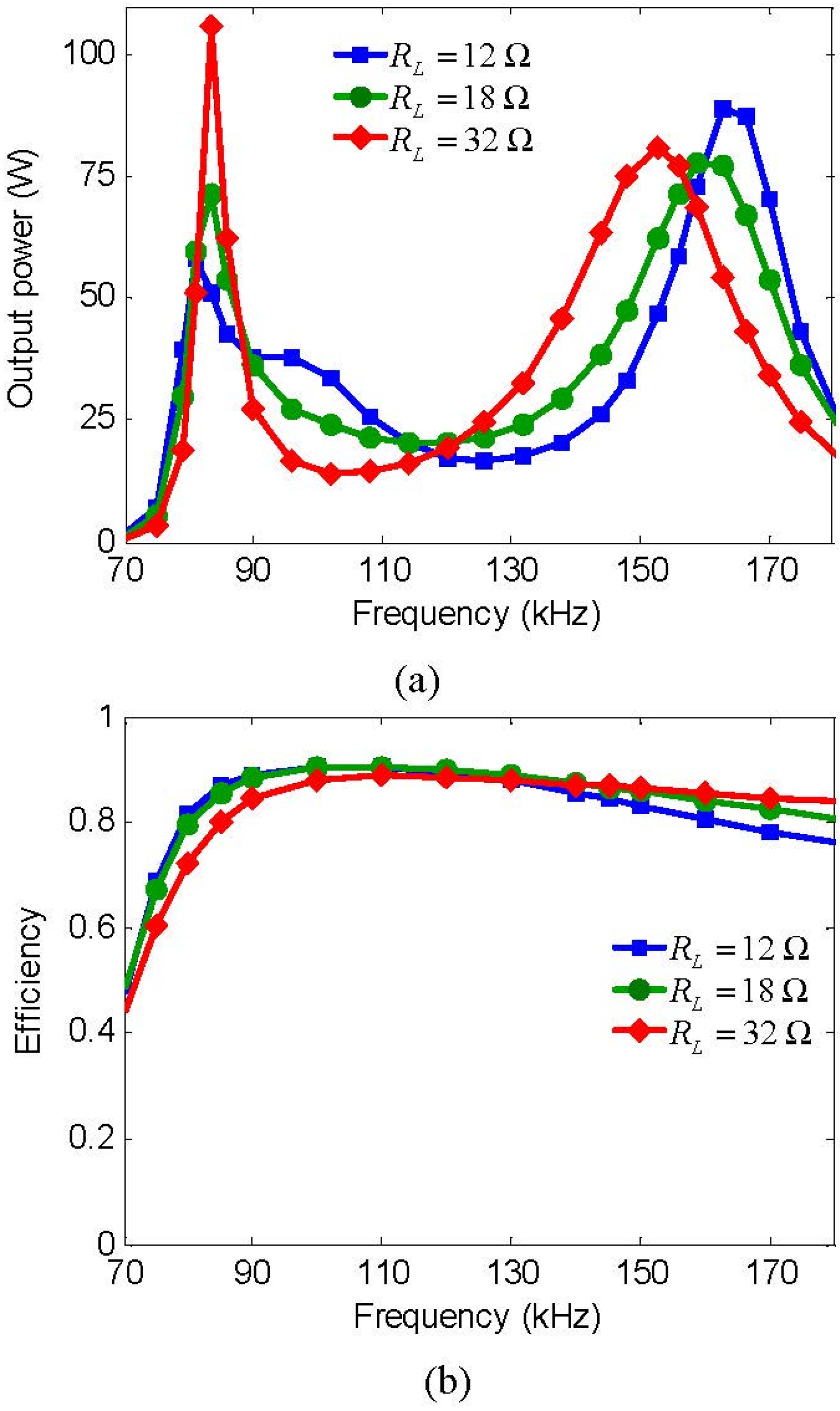
Figure 9a,b reveal how the measured output power and transfer efficiency vary with frequency in a three-coil WPT system, respectively.
As shown in
Figure 8a, in the case of the small coupling coefficients (
i.e., at long distances), when the load resistance is relatively small, there is only peak value of the output power; when the load resistance grows, that is, the quality factor decreases, two peaks of the output power arise because of the frequency splitting [
23].
Figure 9a indicates that when the coupling coefficients are relatively large (
i.e., at close distances), there are two peak values of the output power, which is called the frequency splitting phenomenon [
23].
Figure 8.
Measured results versus frequency in a three-coil WPT when and : (a) output power; and (b) efficiency.
Figure 8.
Measured results versus frequency in a three-coil WPT when and : (a) output power; and (b) efficiency.
Figure 9.
Measured results versus frequency in a three-coil WPT when and : (a) output power; and (b) efficiency.
Figure 9.
Measured results versus frequency in a three-coil WPT when and : (a) output power; and (b) efficiency.
When the load resistance varies, the transfer efficiency in the three-coil WPT system varies accordingly, that is, there exists an optimal load to obtain the maximal transfer efficiency. Comparing
Figure 8b with
Figure 9b, we observe that increasing the coupling coefficients (
i.e., at close distances) results in higher transfer efficiency.
5. Conclusions
Based on circuit theory, load-independent output current in a three-coil WPT system is thoroughly studied. By introducing six factors, namely, the coupling coefficients ( and ), the quality factor (), and the resonant frequency of each coil (, , and ), and substituting these factors into the expression of the RMS of the output current, we propose an intuitive method of calculating the frequency for load-independent output current, which indicates that there are two frequencies that can achieve load-independent output current in three-coil WPT. An experimental setup is implemented, and the measured results show excellent agreement with the theoretical analysis. Furthermore, the measured results of output power and transfer efficiency in a three-coil WPT system are also presented.
In comparison with previous study [
18], this study can assist us in achieving a load-independent output current at longer distances. The proposed method and conclusion provide guidelines for selecting the optimal operating frequency in three-coil WPT system to obtain a constant output current under varying load conditions, which is a significant progress toward practical applications for WPT technology.


