Physical property and hydrogen uptake data for titanium powder were used in a numerical model to predict hydrogen uptake and release rates for several candidate prototype designs. COMSOL Multiphysics was used to make performance predictions for cylindrical hydride beds with varying diameters and thermal conductivities. The modeling results imply that 3 kWh of thermal storage per day can be achieved using two 12.7-cm (5 in) diameter, 29 cm (11.5 in)-long cylinders filled with titanium hydride powder and 8% dense, reticulated copper foam. The basis for this conclusion is provided in the subsections that follow.
2.4.1. Numerical Model Development
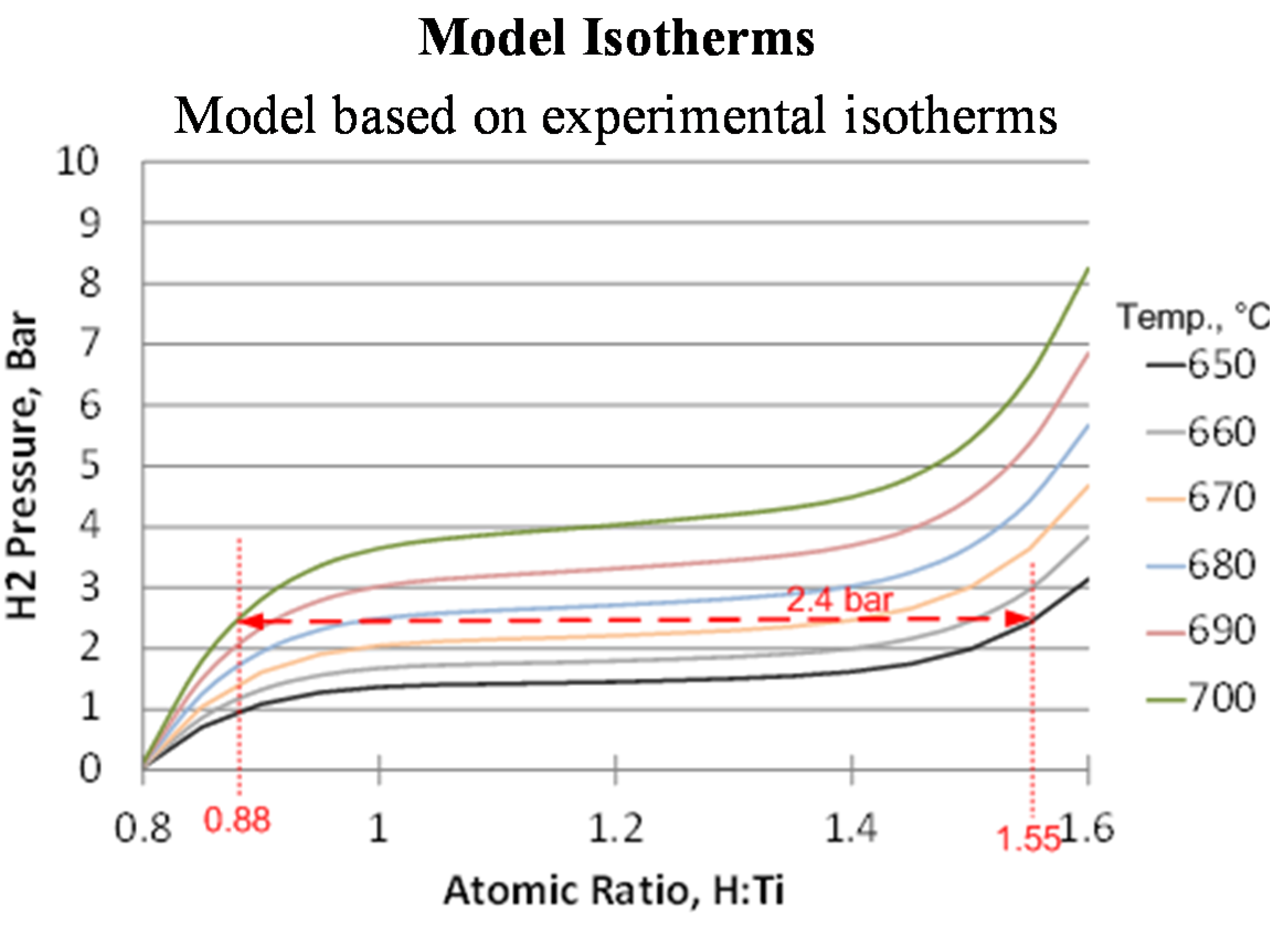
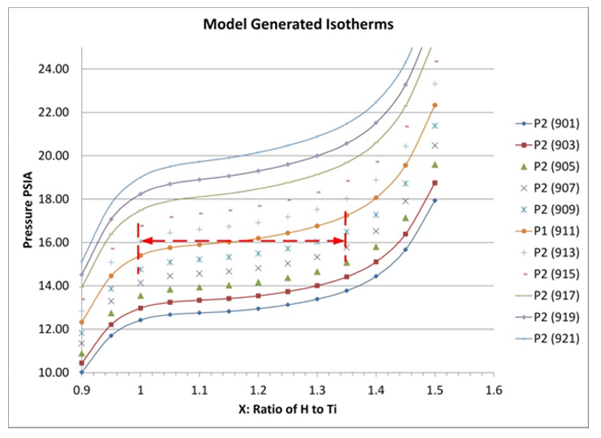
The prototype energy storage system is intended to operate at near-constant pressure and to use a temperature swing of ±10 °C to drive the uptake and subsequent release of hydrogen. As the temperature in the bed changes, the concentration of stored hydrogen responds accordingly. The relationship between stored hydrogen equilibrium pressure, temperature and the heat of reaction can be determined based on a Clausius-Clapeyron expression of the form:
where
T is absolute temperature in Kelvin,
R is the gas constant (8.314 J/mol K),
Q is the heat of adsorption in J/mol and
P is pressure. This can be rearranged to yield pressure
P2 at a temperature
T2 if the values
P1 and
T1 are known from an isotherm:
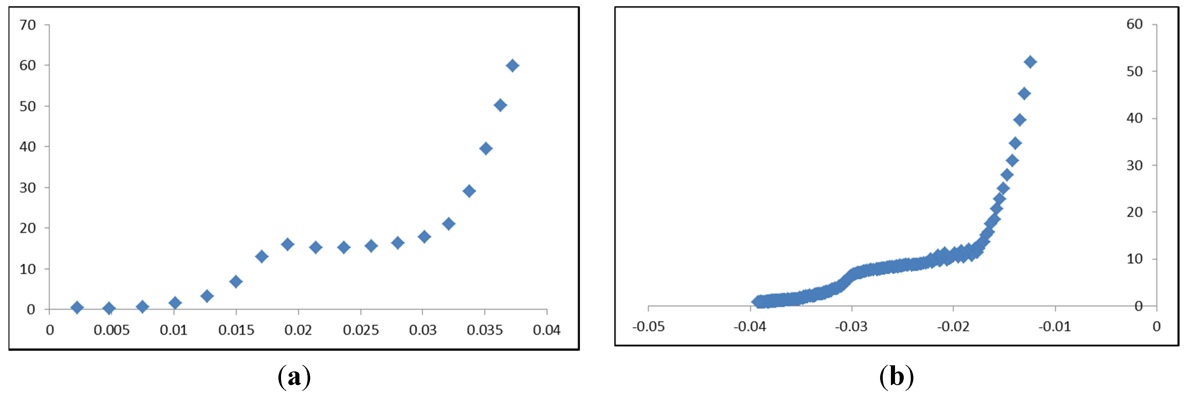
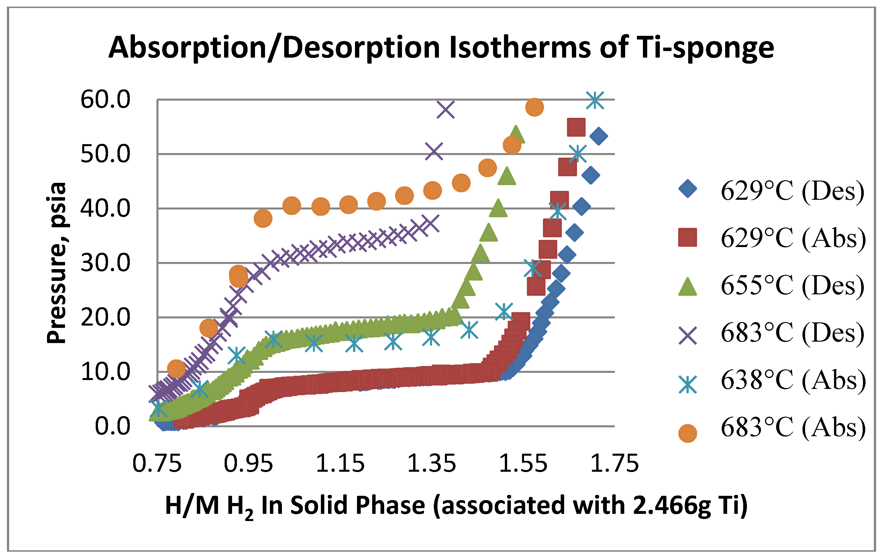
This expression requires an isotherm from which to extrapolate. For our modeling, we measured an isotherm for titanium hydride at 638 °C and then used these data to predict the variation with temperature of the hydrogen concentration in the hydride bed at a constant pressure of 1.10 atm (16.13 psia; 1.1 bar). This relationship was used in the subsequent modeling of the hydride beds. In addition to the uptake/release dependence on temperature, modeling of the hydride beds requires estimates for the hydride bulk density, thermal conductivity, heat capacity and the heat of reaction between hydrogen and titanium.
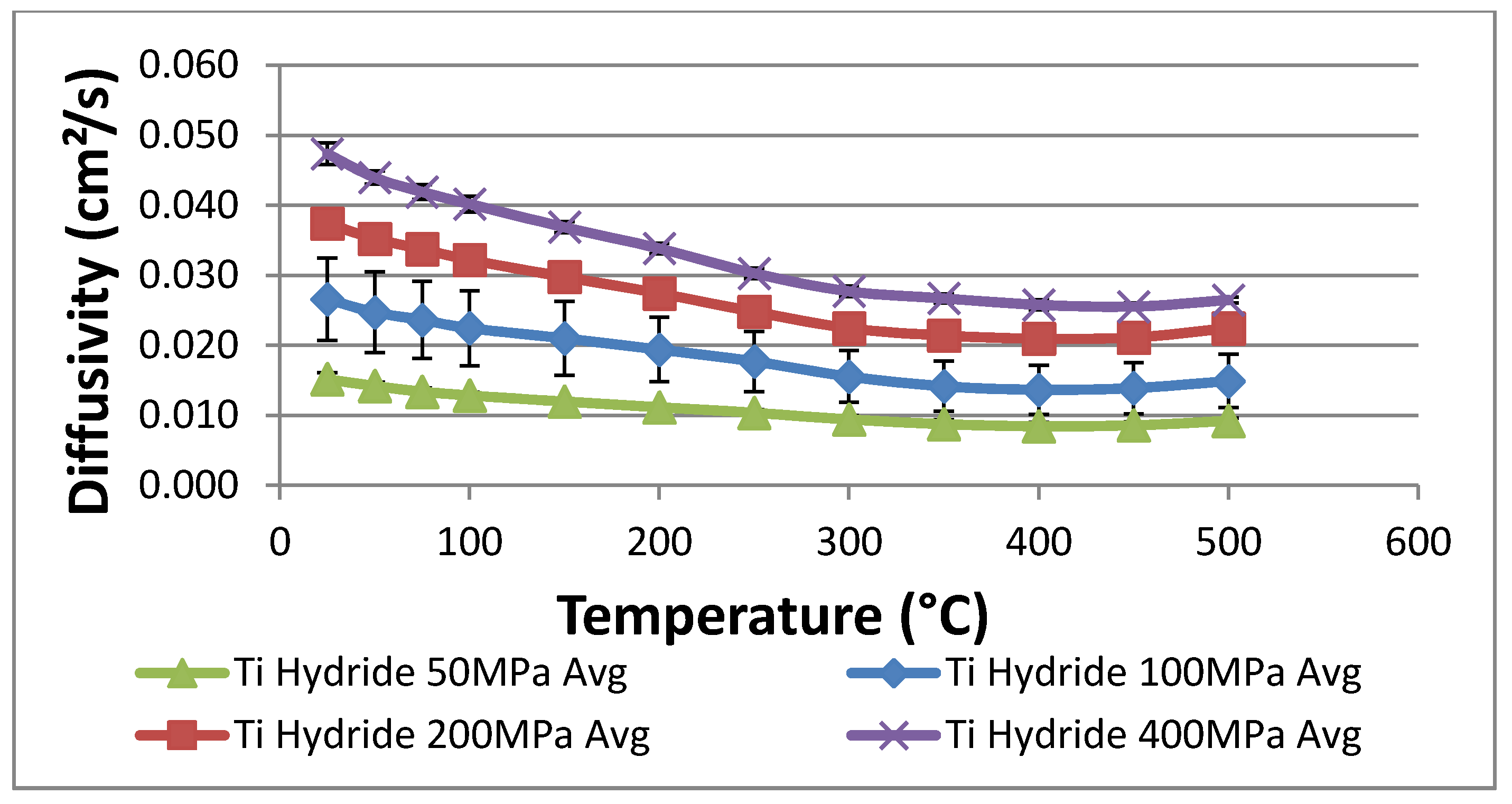
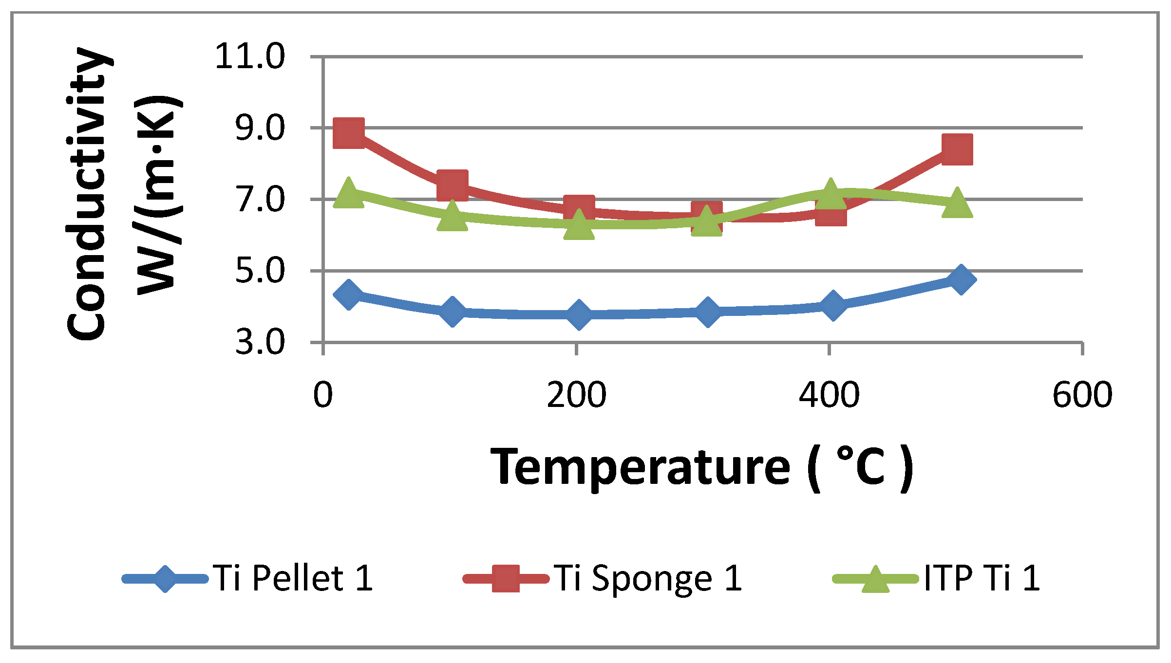
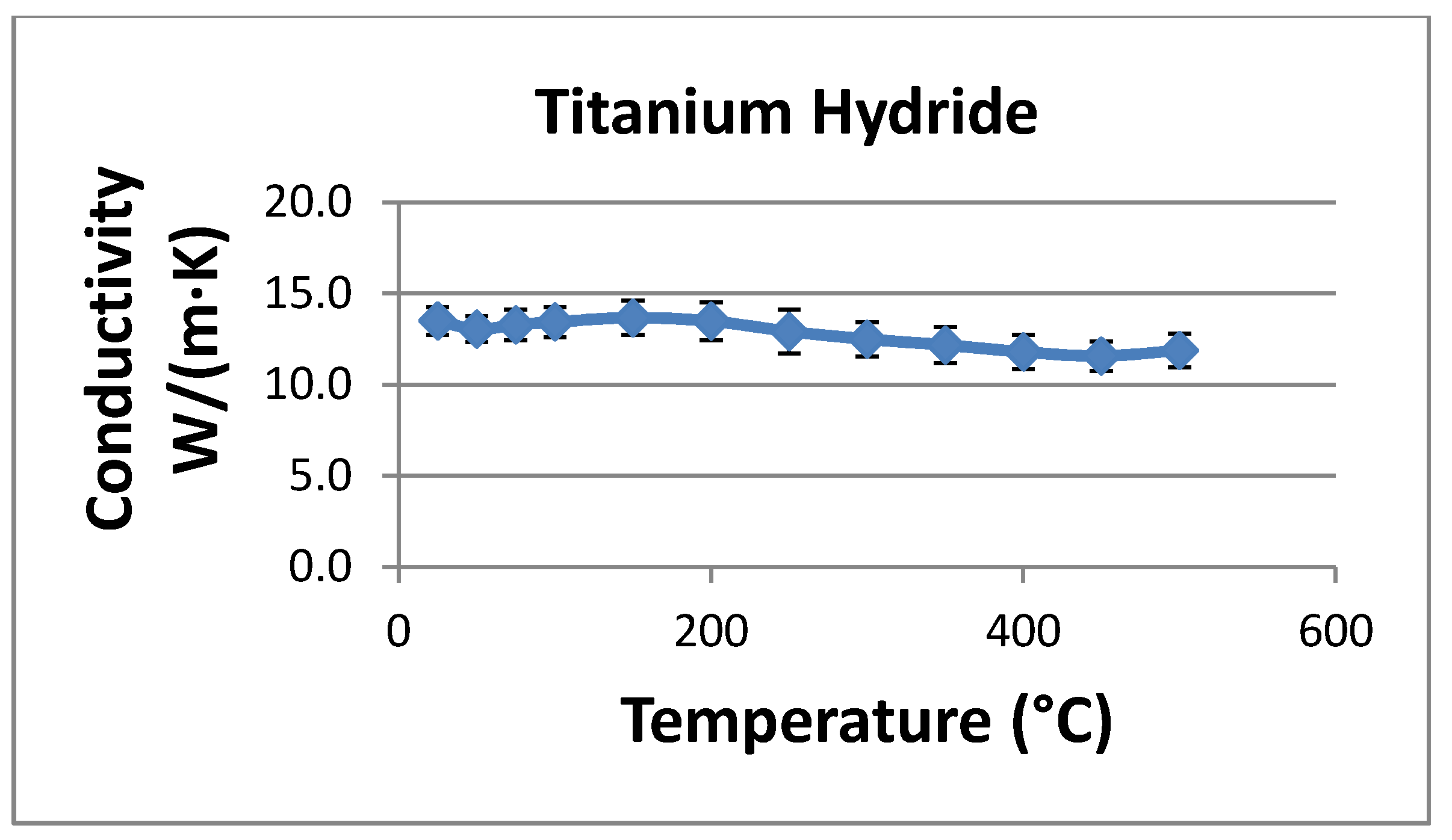
The powder density was taken to be 3038 kg/m3 based on the average measured density of the titanium pellets used in the laser flash experiments described previously. Heat capacity was set equal to 600 J/kgK based on literature values for titanium in the temperature range of interest (roughly 638 °C).
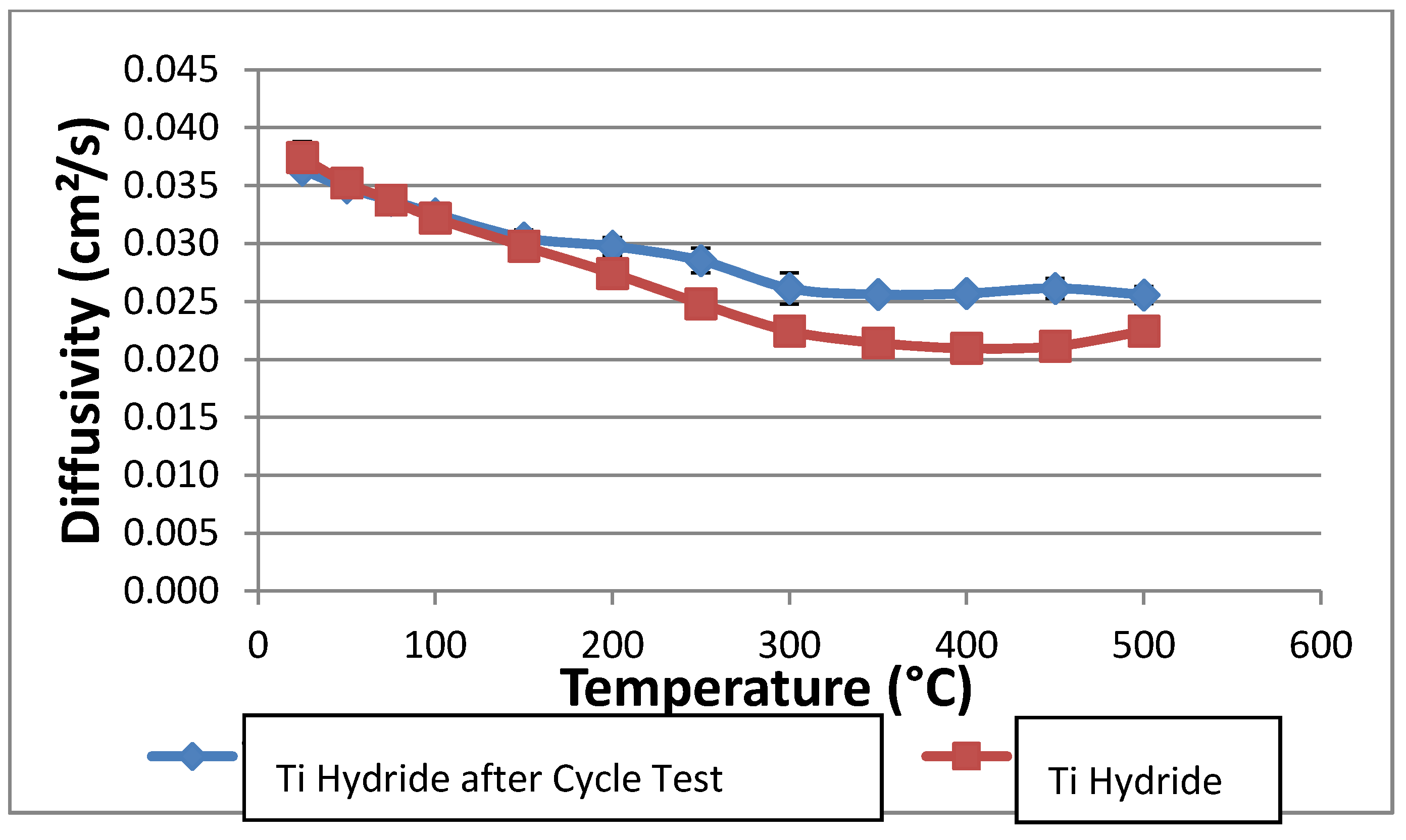
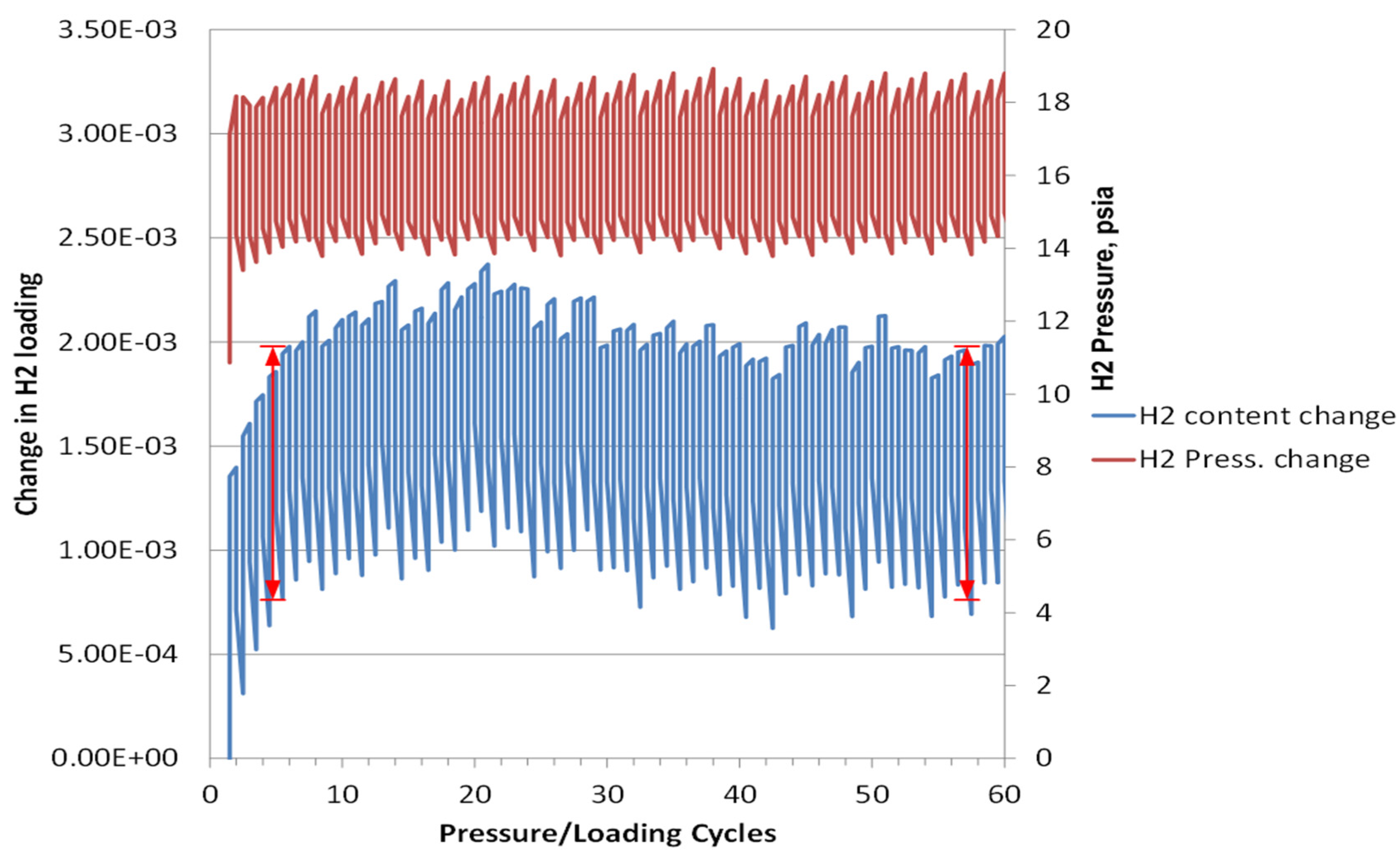
The thermal conductivity of the powder was set to 0.2 W/mK. This value is significantly lower than measured in the laser-flash experiments, but it is expected to reflect the reduced conductivity of a hydride bed after many thermal cycles. Repeated cycling may break up the hydride into relatively small (~2–20 microns) particles, and this effect will reduce the bulk thermal conductivity to between 0.1 and 0.4 W/mK. We measured the thermal conductivity after several cycles as described above without seeing a particle size reduction; however, the thermal conductivity reduction may not be pronounced until after several hundreds or thousands of cycles. Rather than rely on the higher thermal conductivities measured in the laser flash experiments, we chose to use a conservatively low bed thermal conductivity to ensure that the prototype system will meet the design objectives. The heat of reaction for hydrogen and titanium hydride varies somewhat with the fraction of hydrogen stored in the hydride. Data for the reaction enthalpy were correlated with stored hydrogen concentration and entered into the numerical model. Over the concentration range of interest, the heat of reaction varies between about 140 and 155 kJ per mole of H2 reacted.
The COMSOL models for the heat-storage prototypes were set up assuming radial symmetry within the device. COMSOL was used to solve the dynamic heat conduction equation with a simultaneous chemical reaction:
where
T is the local temperature,
q is the heat generation rate from the hydride reaction,
r is radial direction,
t is time,
k is the hydride powder thermal conductivity,
r is the hydride bulk density and
Cp is the hydride heat capacity.
The relevant boundary conditions for the model are: (1) no heat loss or gain from the ends of the cylinder; and (2) temperature changes of the outside cylindrical surface are specified numerically as a function of time as described in the text of the next section. The concentration of hydrogen bound in the hydride material was tracked as a function of radial position and time. At time = 0, the hydride was assumed to be fully saturated with hydrogen at the specified starting temperature and pressure. An outside wall temperature change was then applied sigmoidally over a 30-s duration, and the changes in radial temperature and hydrogen concentration profiles were tracked over time thereafter. Reaction kinetics were assumed fast compared to the relatively slow process of heat conduction through the hydride powder, so in the model, the local bound hydrogen concentration was set equal to its equilibrium value based on the local temperature and specified hydrogen gas pressure.
2.4.2. Modeling Results
Initial modeling efforts focused on predicting the rate of hydrogen release from cylindrical beds of hydride powder. For these calculations, the bed was initially assumed to be at 635 °C and loaded to 1.35 moles hydrogen per mole of titanium. At time = 0, the outside wall of the cylinder is rapidly heated to 645 °C, and hydrogen is released as progressively more of the bed is heated. With each mole of hydrogen released, however, approximately 150 kJ of heat is required to drive the reaction, so heating the bed proceeds much more slowly than it would if there were no reaction taking place.
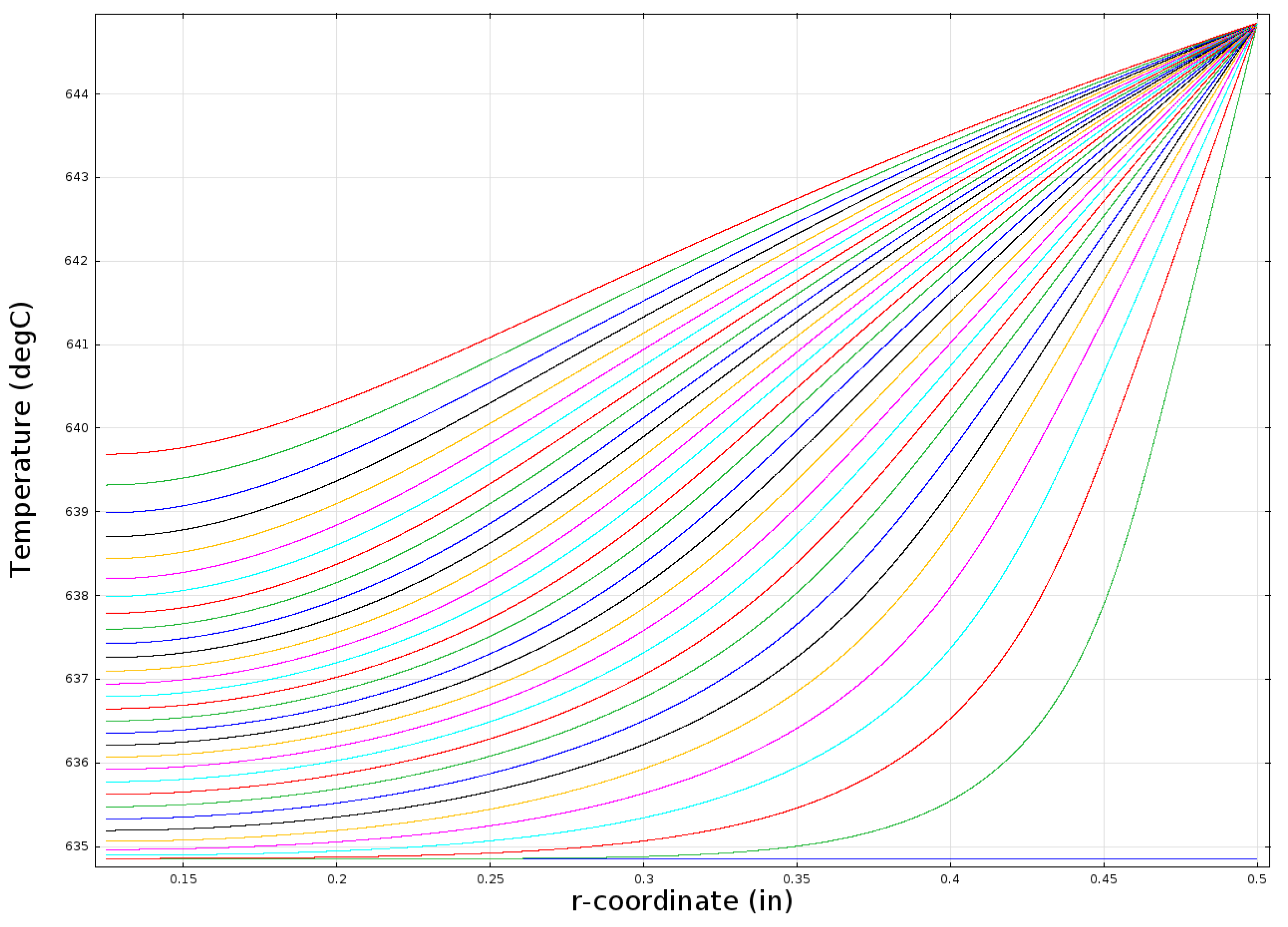
Figure 10 shows a series of radial temperature profiles within a one inch-diameter bed starting with the blue line at the bottom for time = 0 (T
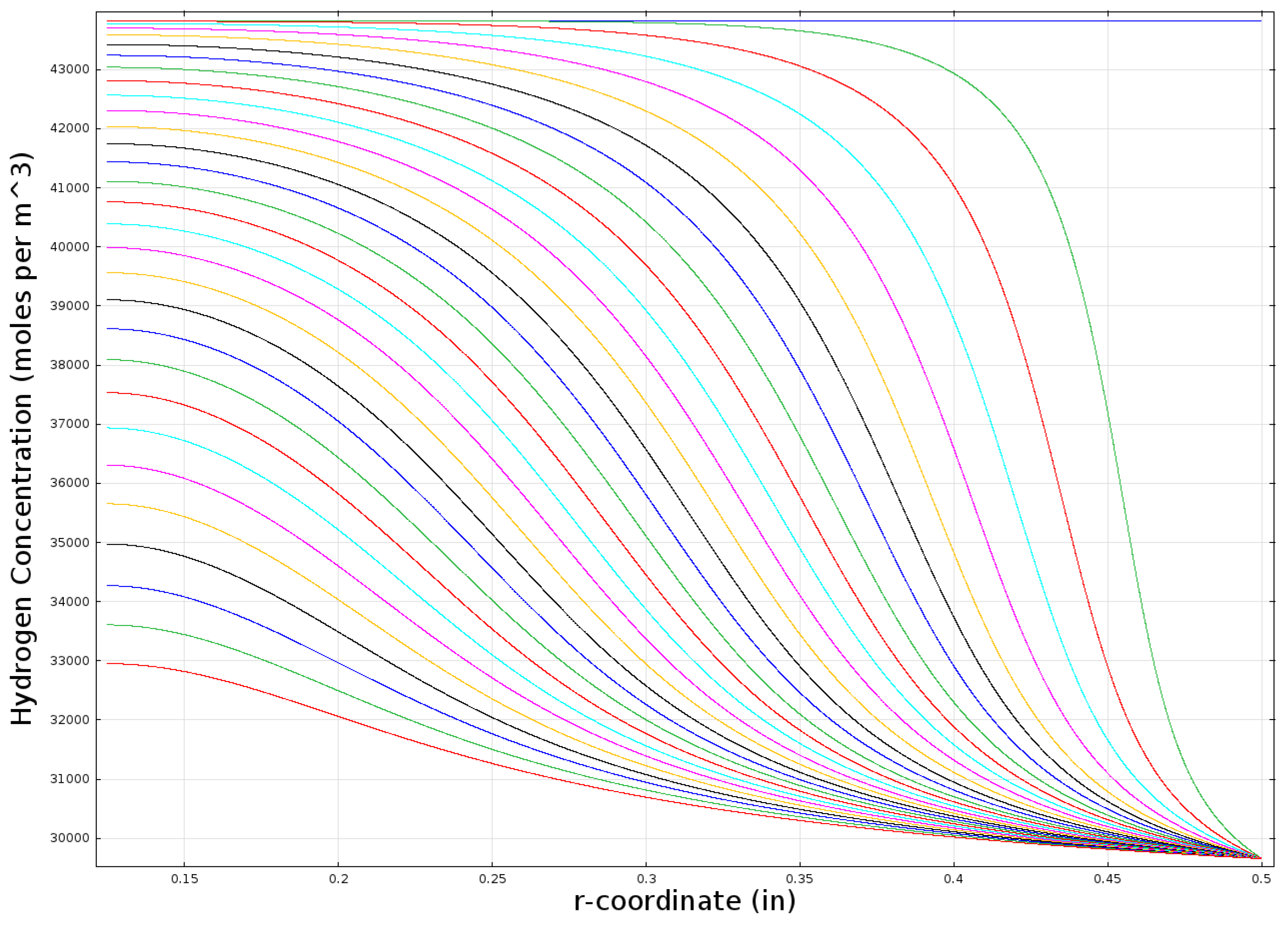
init = 634.85 °C = 908 K) and then moving from right to left with each successive line representing 20 min of elapsed time. The left-most line (colored red) indicates the temperature profile after 10 h. The r-coordinate in the graph starts at 3.2 mm because the bed geometry is assumed to include a 6.4-mm (0.25-in) outside diameter, porous metal tube that is included to facilitate the addition and removal of hydrogen.
Figure 11 shows a similar plot for the hydrogen concentration within the bed.
Figure 10.
Modeled temperature profile in a one inch-diameter cylindrical bed (k = 0.2 W/mK).
Figure 10.
Modeled temperature profile in a one inch-diameter cylindrical bed (k = 0.2 W/mK).
Figure 11.
Modeled hydrogen concentration profile in a one inch-diameter cylindrical bed (k = 0.2 W/mK).
Figure 11.
Modeled hydrogen concentration profile in a one inch-diameter cylindrical bed (k = 0.2 W/mK).
The heat-storage prototype is designed with the assumption that the bed is cycled once per day with approximately 6 h of hydrogen loading, 6 h of thermal equilibration, 6 h of unloading and, then, six more hours of thermal equilibration. The one inch-diameter bed still contains a substantial fraction of its loaded hydrogen after 6 h of heating, so the one inch diameter is likely a bit larger than we desire for our prototype system.
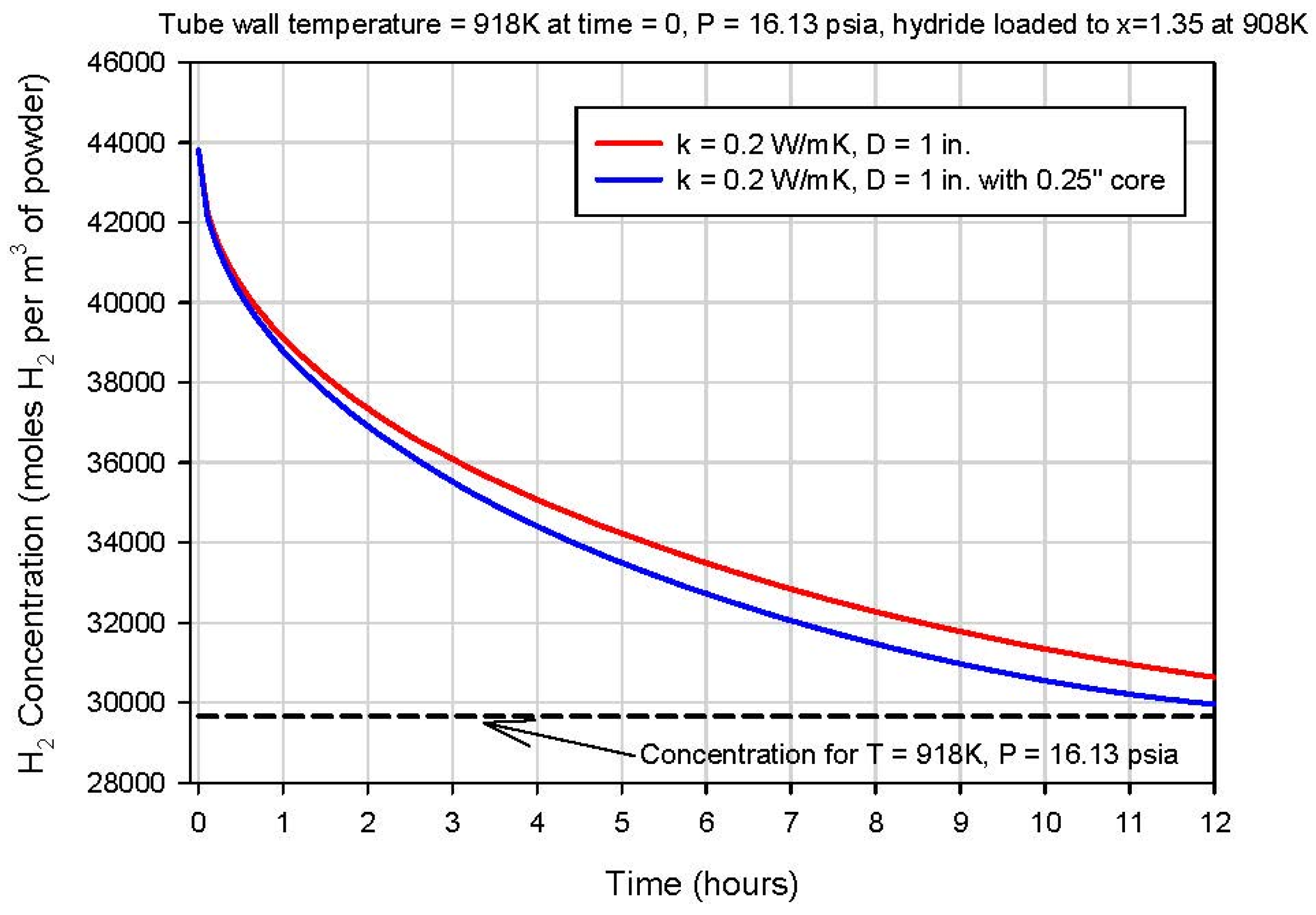
Figure 12 shows the averaged hydrogen concentration within the bed as a function of time for a bed with and without the central 6.4 mm (0.25 in)-diameter porous metal core. Roughly 10 h is required to reduce the hydrogen concentration to about 10% of its initial value. Similar simulations were run for alternative tube diameters, and the hydrogen-release time was found to scale approximately with the square of the tube diameter. A bed diameter of approximately 1.9 cm (0.75 in) yields a hydrogen release time of about 6 h, which is the nominal target for the demonstration system.
Figure 12.
Modeled average hydrogen concentration in the hydride bed vs. time for a one-inch diameter.
Figure 12.
Modeled average hydrogen concentration in the hydride bed vs. time for a one-inch diameter.
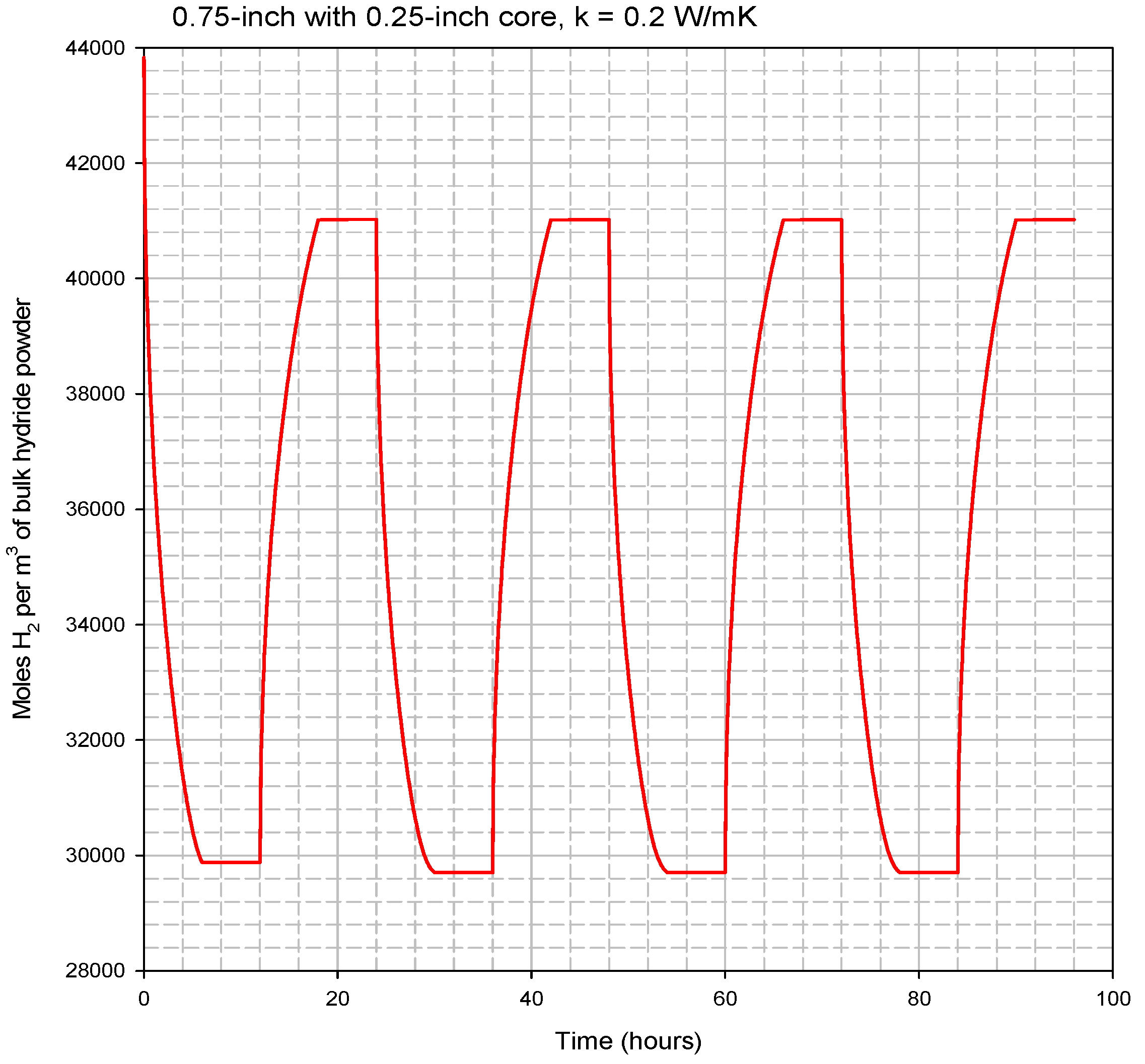
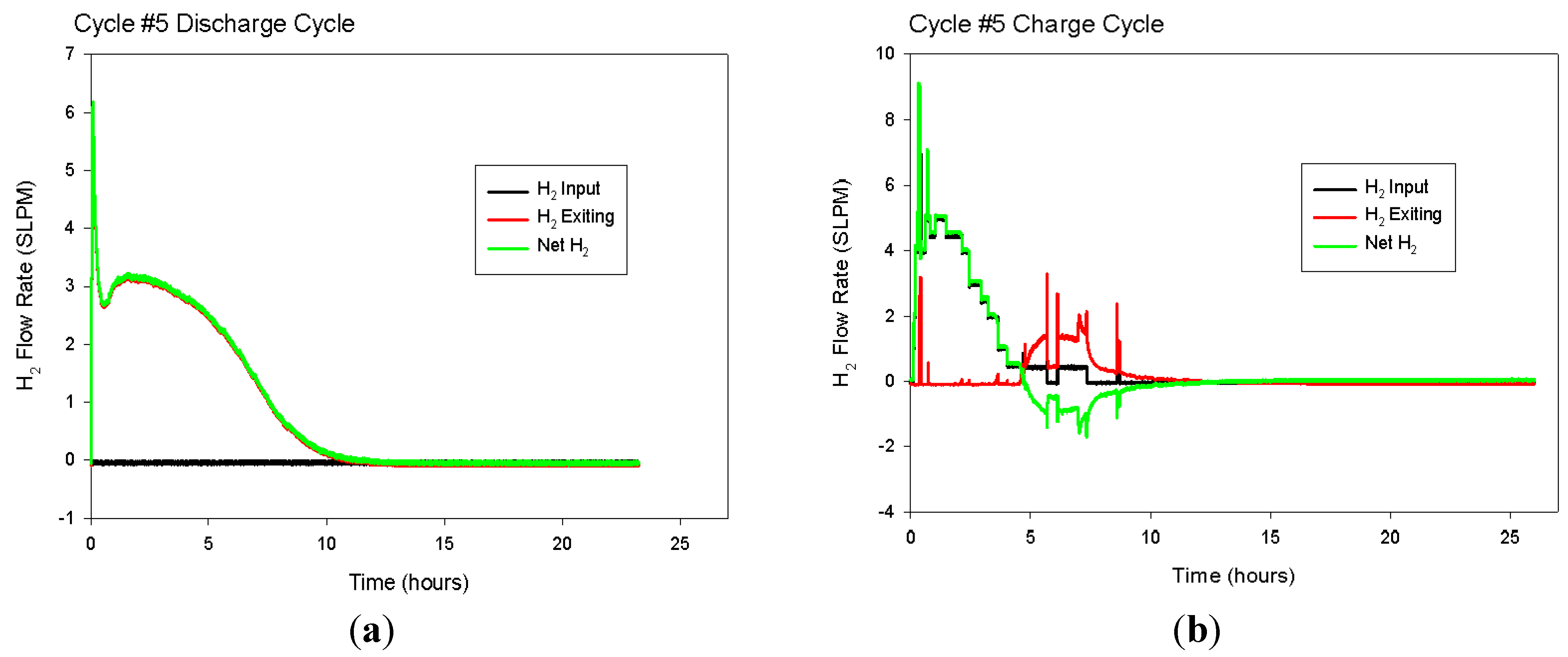
Multiple load/unload cycles were simulated for the 1.9 cm (0.75 in)-diameter hydride bed with a 0.63 cm (0.25 in)-diameter porous tube along its axis. The hydride was assumed to be loaded to 1.35 moles of hydrogen atoms per mole of titanium atoms. This condition represents the maximum expected loading at 635 °C and 16.13 psia. At time = 0, the exterior wall of the cylinder is assumed to be heated to 645 °C and held constant for the next 6 h, while hydrogen is released and the gas pressure in the bed is held constant at 1.1 atm (16.13 psia). At time = 6 h, the heat flow into the bed is stopped, and the bed is allowed to come to thermal equilibrium until time = 12 h. At time = 12 h, the exterior wall of the cylinder is decreased back to 635 °C. Between time = 12 h and time = 18 h, the hydrogen concentration in the bed increases as the bed is cooled as it delivers stored heat and hydrogen gas is supplied from an external source at 1.1 atm. Finally, between time = 18 h and time = 24 h, the heat flow out of the bed is stopped, and the bed is allowed to come to thermal equilibrium. The cycle is then repeated starting at time = 24 h, when the exterior wall is again heated to 645 °C.
During each 24-h cycle, the applied exterior-wall temperature swings between 635 °C and 645 °C. This 10-degree temperature swing is only half of the 20-degree swing available for the prototype system. We limited the temperature swing in the model to 10 degrees to ensure that there is adequate temperature driving force available between the heating/cooling fluid and the exterior surface of the hydride bed. The 10-degree driving force should be sufficient for gas-phase convective heating/cooling of the hydride bed.
Figure 11 shows the results for cylinders ranging in size from 10 cm (4 in)–15 cm (6 in). In all cases, we assumed that there is a 1.3-cm (0.5 in) porous-metal tube in the center of the bed to facilitate the addition and removal of hydrogen gas.
The 12.7 cm (5 in)-diameter cylinder is predicted to yield roughly 90% hydrogen release after the targeted 6 h of heating, so the performance of a cylinder with this diameter was simulated for four complete 24-h cycles.
Figure 12 shows the predicted volume-averaged hydrogen concentration inside the bed during all four cycles. Then, much less than a 10-degree temperature driving force will be needed, and the hydride bed performance will be better than predicted by our modeling results.
Figure 13 shows the volume-averaged concentration of hydrogen in the bed for four complete load/unload cycles. After the first couple of cycles, the high and low bed concentrations stabilize for all subsequent cycles at 41.02 and 29.71 moles H
2 per liter of bed volume. To store 3 kWh of heat during every 24-h cycle, about 72 moles of H
2 must be loaded and unloaded. Each mole of H
2 represents roughly 150 kJ (41.7 Wh) of heat, because the heat of reaction is 150 kJ/mole. The total required bed volume can be estimated by dividing the required 72 moles of H
2 by the difference between high and low bed H
2 concentrations (41.02 − 29.71 = 11.31 moles per liter). The result is an estimated required hydride volume of 6.36 liters. If each hydride bed is 46 cm (18 in) long and 1.9 cm (0.75 in) in diameter with a 0.63 cm (0.25 in)-diameter porous tube along the axis, then a total of 55 such tubes will be required to achieve the targeted 3 kWh of heat storage per cycle.
Figure 13.
Modeled four complete cycles for the 1.9 cm (0.75 in)-diameter hydride bed.
Figure 13.
Modeled four complete cycles for the 1.9 cm (0.75 in)-diameter hydride bed.
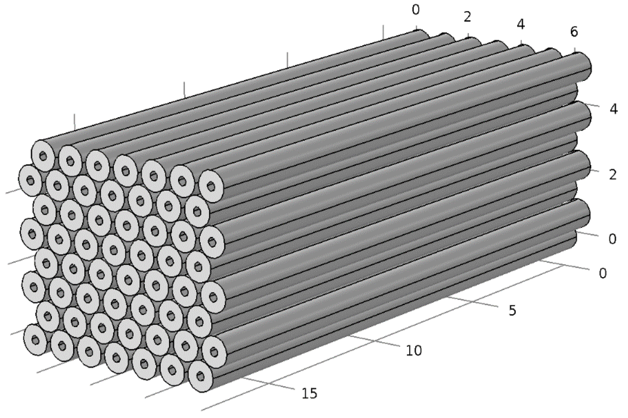
The 55 tubes can be arranged in an array roughly 19 cm (7.5 in) wide, 16.5 cm (6.5 in) high and 46 cm (18 in) long, as shown in
Figure 14. Each tube has an inside diameter of 1.9 cm (0.75 in) and an outside diameter of 2.22 cm (0.875 in). The total volume occupied by the array of tubes is 14.4 liters.
Figure 14.
Close-packed array of 56 tubes, each 2.2 cm (0.875 in) in diameter and 46 cm (18 in) long. The dimensions shown on the background grid are inches.
Figure 14.
Close-packed array of 56 tubes, each 2.2 cm (0.875 in) in diameter and 46 cm (18 in) long. The dimensions shown on the background grid are inches.
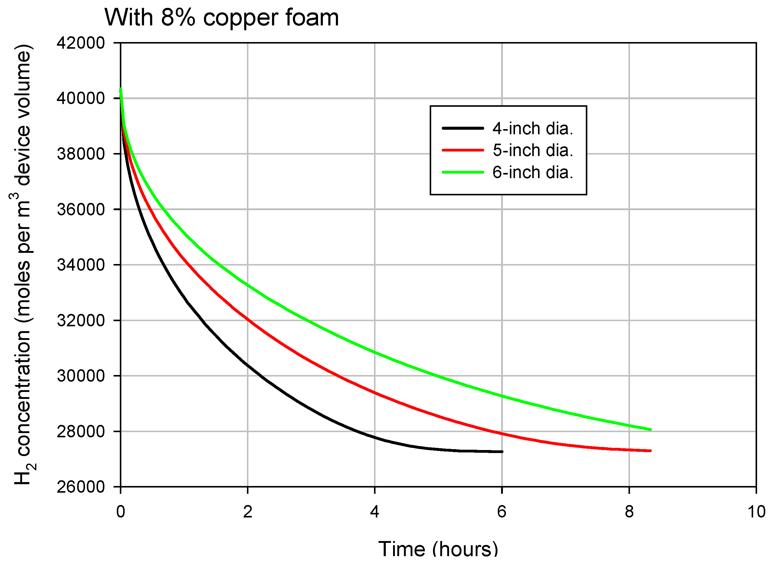
To reduce the volume occupied by the bed and allow for better heat transfer and more design flexibility, we considered a second geometry in which the hydride powder is loaded into a single, larger-diameter cylinder that includes 8% dense (92% void space) reticulated copper foam with an estimated thermal conductivity of 9.3 W/mk. Simulations were performed for multiple cylinder diameters to determine the diameter that yields the desired hydrogen release time of approximately 6 h; when the cycles stabilize, the hydrogen concentration shifts between a high of 37.35 moles per liter and a low of 27.49 moles per liter. The modeled hydrogen release from cylinders with various inside diameters containing copper foam is shown in
Figure 15. Using the same calculation method described earlier for the 1.9-cm tubes, we determine that a total of 7.3 liters of bed volume is required for 3 kWh of heat storage per cycle. For the 12.7-cm (5 in) cylinder diameter, a total cylinder length of 58 cm (23 in) is required for 7.3 liters of bed volume, and the external volume of the device is just under 7.7 liters. The cylinder containing copper foam, then, has a volume just over half that of the array of 55 tubes (14.4 liters).
Figure 15.
Modeled hydrogen release from cylinders with various inside diameters containing copper foam.
Figure 15.
Modeled hydrogen release from cylinders with various inside diameters containing copper foam.


