Article

Electromagnetic Design and Analysis of a Novel Fault-Tolerant Flux-Modulated Memory Machine

Department of Electrical Engineering, the Hong Kong Polytechnic University, Hong Kong, China
*
Author to whom correspondence should be addressed.
Energies 2015, 8(8), 8069-8085; https://doi.org/10.3390/en8088069
Submission received: 8 June 2015 / Accepted: 28 July 2015 / Published: 3 August 2015

Abstract

:
Electric machines play an important role in modern energy conversion systems. This paper presents a novel brushless fault-tolerant flux-modulated memory (FTFM) machine, which incorporates the merits of a flux-modulated permanent magnet machine and multi-phase memory machine and is very suitable for applications that require wide speed ranges of constant-power operation. Due to the magnetic modulation effect, the FTFM machine can produce a large torque at relatively low speeds. Due to the usage of aluminum-nickel-cobalt (AlNiCo) magnets, this machine can readily achieve a flexible air-gap flux controllability with temporary DC current pulses. Consequently, the constant-power region is effectively expanded, and the machine's efficiency during constant-power operation is increased. Due to the multi-phase armature winding design, the FTFM machine enables lower torque ripple, increased fault tolerance ability and a higher possibility of splitting the machine power through a higher number of phases, thus the per-phase converter rating can be reduced. The design methodology and working principle of this kind of machine are discussed. The electromagnetic performances of the proposed machine are analyzed using the time-stepping finite element method (TS-FEM).

1. Introduction

Electric machines have a prominent role in modern energy conversion systems, such as wind power generators and electric vehicles (EVs) [1,2,3,4,5]. Due to the high torque density and high efficiency, permanent magnet machines have been widely used. To satisfy different requirements, such as constant-voltage power generation for wind generations or wide-speed range constant power operation in EVs, the air-gap magnetic flux needs to be regulated readily. For traditional permanent magnet (PM) machines, flux weakening can be indirectly achieved by applying a large negative d-axis current [6]; however, this method not only needs a complex control strategy, but also reduces the machine efficiency caused by the high excitation currents. In addition, the rotor position also needs to be predicted accurately when the PMs are located on the rotor [7].
To simplify the control strategy and directly control the magnetic flux provided by PMs, some new topologies of machines with auxiliary field windings are investigated. In [8], a doubly-fed doubly-salient machine with all of the PMs employed on the stator side has been proposed, and AC armature windings and DC field windings are incorporated within one stator. Therefore, the magnetic field provided with stator PMs can be directly regulated by the DC field currents. This concept can easily achieve flux controllability and simplify the rotor structure, but the continuous excitation losses cause unnecessary power consumptions. To reduce the copper losses caused by the field regulations, neodymium-iron-boron (NdFeB) PMs are replaced with AlNiCo PMs, and a flux-mnemonic stator-PM machine is proposed for constant-voltage generation in wind power generation systems [9]. However, AlNiCo PM has a much lower energy product compared to NdFeB PM material, and the power density of machine is degraded accordingly. To overcome this problem, dual-mnemonic machines, which use AlNiCo and NdFeB combined with PM arrangements, are proposed in [10]. However, when all PM materials are located on stator side, the flux leakage problems are serious, which limits the effective torque production of the PM machine. Up to now, there has been no report about the stator and rotor dual PM brushless memory machine.
This paper presents a novel FTFM machine, which can not only realize effective flux regulation with reduced power losses, as well as improved fault tolerance ability, but also produces high torque density due to the stator and rotor dual PM design. The inspiration of this proposed machine arises from magnetic gears (MGs), especially from the bidirectional flux-modulated MG. Figure 1a shows the structure of a high-performance magnetic gear (MG) based on the field modulation effect and which has become very attractive, by virtue of its intrinsic merits of having high torque density, high efficiency, reduced acoustic noise and low maintenance [11]. An improved MG with a bidirectional modulation effect is investigated in [12], as shown in Figure 1b. This structure can not only increase the torque density of MG, but also improves the mechanical strength of the modulation ring. Inspired by this idea, a series of magnetic geared machines have been proposed [13,14,15,16], since most of these machines have higher torque densities than conventional PM machines. However, a noticeable shortcoming that limits the wide use of PM machines in traction applications is that they cannot readily achieve flux weakening control due to their fixed PM excitation [17]. Consequently, the constant-power operating range of PM machines is limited.
In the FTFM machine, NdFeB PMs are located in the rotor side to produce torque effectively, and AlNiCo PMs are housed in the outer stator, which enables a flexible and direct flux-tuning capability. The air-gap flux can be regulated effectively by applying a temporary DC current pulse, so the constant power region can be expanded, and the machine efficiency under flux weakening control will be increased because of the negligible DC excitation losses. This machine is designed with five phase armature windings, which can effectively reduce the torque ripple, improve fault tolerance ability and increase the design freedoms of armature windings. The configuration and working principle of this machine is discussed in this paper. The electromagnetic performance is analyzed using the TS-FEM. As one of the most important properties of multiphase PM machines, the fault tolerance capability of the proposed machine is investigated in detail.
Figure 1. Configuration of the magnetic gear (MG): (a) Conventional MG; (b) triple-PM MG. PM: permanent magnet.
Energies 08 08069 g001

2. Configuration and Working Principle

2.1. Configuration of the Proposed Fault-Tolerant Flux-Modulated Memory (FTFM) Machine

Figure 2a shows the configuration of the proposed machine, which is made up of three components, one inner stator, one outer stator and one rotor sandwiched between two stators. Two sets of consequent pole PMs are employed, one on the outer stator using AlNiCo PMs and the other on the rotor using NdFeB PMs. Both rotor PMs and stator PMs are radially magnetized. Each PM and its adjacent iron tooth/ferromagnetic segment will form a pair of magnetic poles.
The design of the FTFM machine is inspired by MGs, but the rotating magnetic field previously provided by inner rotor PMs in MGs is now replaced by the five-phase stationary armature windings in the inner stator, while the outer stator magnetic flux in the MG is replaced by the outer stator employed with both DC windings and AlNiCo PMs. The middle modulation ring, which is comprised of ferromagnetic segments and NdFeB PMs, can serve as the rotor in the machine. Similar to the modulation ring in the triple magnet MG, the difference of permeability between the PMs and steel segments allows both the rotor and outer stator to produce field modulation, namely bi-directional field modulation, which is the key to ensure effective magnetic coupling among the magnetic fields excited by the armature windings and the two sets of PMs [18]. The five-phase armature windings are housed in the inner stator slots and DC field windings in outer stator slots.
Since the AlNiCo magnet inherently owns a low coercivity and non-linear B-H curves, the air-gap flux can be regulated directly by the application of temporary current pulse in the DC windings. The AlNiCo PMs mounted on the outer stator can be readily magnetized/demagnetized, since they have low coercivity and non-linear B-H curves. By applying a temporary DC current pulse, the operating point of the AlNiCo PMs can be changed, hence the air-gap flux density can be regulated effectively. The DC excitation losses are negligible, since only a temporary current pulse is needed, so this machine will enjoy higher efficiency when under flux weakening control.
Figure 2. Configuration and mechanical structure of the proposed machine: (a) Configuration; (b) mechanical structure.
Energies 08 08069 g002
The mechanical structure of the proposed machine is shown in Figure 2b. PMs on the outer stator are surface mounted using superglue. Since the rotor is sandwiched between the two stators, the cup rotor structure is artfully used to facilitate the machine assembly. The rotor PMs are glued inside the rotor slots, as there exists great centrifugal force when the rotor is rotating at a high speed, and the wedge structure is employed at the outer air-gap side to keep the rotor’s integrity.

2.2. Working Principle

The fundamental working principle of the proposed FTFM machine is based on the “magnetic gearing effect”. As one can see from the machine configuration, both the rotor and outer stator serve as the modulation ring; hence, a bi-directional field modulating effect can be achieved. This also means that apart from the fundamental component of magnetic field, abundant field harmonics will be produced.
According to the Maxwell equations, the two interacted magnetic harmonics should have the same pole pairs and the same rotational speed, in order to transmit steady torque at different speeds. Based on the magnetic-gearing effect, the pole pair number of the outer stator PMs ps, the pole pair number of the rotor pr and the pole pair number of the armature windings pa are governed by:
p r = p s + p a
To achieve flux controllability, the pole pair number of DC windings pd should be equal to the pole pair number of the outer stator PMs ps:
p d = p s
and the number of the outer stator slots Ns is governed by:
N s = 2 p d

3. Analysis Approach

The key element for a memory machine is the use of AlNiCo PMs. Its low coercivity makes it an attractive material to achieve online magnetization/demagnetization. Furthermore, since AlNiCo owns nonlinear demagnetization characteristic, the recoil line will never superpose on the demagnetization curve. Therefore, when the demagnetization current is applied and then removed during flux weakening, the operating point of AlNiCo will move back along the recoil line and settle at a lower magnetization level, which means that the magnetization level is memorized. Besides the online magnetizing capability, AlNiCo PM also owns high thermal stability and high chemical stability, which make it the natural choice for memory machines.
The hysteresis modeling of AlNiCo magnet is an important issue to control its working point precisely. A linear hysteresis model of AlNiCo PM is proposed [19] as illustrated in Figure 3. In this model, it is assumed that the major hysteresis loop and all of the minor hysteresis loops own the same value of coercivity, but with different values of remanence. It can be seen that the intersection of the recoil line and the load line will uniquely determine the working points of the AlNiCo PM. During the initial magnetizing stage, the operating point will move along OAMP in Figure 3 and settle at Point P with corresponding remanence Brk. If a temporary positive magnetizing force H is applied, the operating point will move along PMBQ and settle at Q with corresponding remanence BrQ. Otherwise, when a temporary negative demagnetizing force H is applied, the operating point will move along PNCR and settle at R with corresponding remanence BrR.
Figure 3. Linear hysteresis model of aluminum-nickel-cobalt (AlNiCo) [19].
Energies 08 08069 g003
As shown in Figure 3, the equations of Lines l1 to l4, which represent the magnetizing and demagnetizing processes, can be respectively expressed as:
Line l1:
B = μ r μ 0 H + B r k , k = 1 , 2 , 3...
Line l2:
B = μ r μ 0 H B r k , k = 1 , 2 , 3...
Line l3:
B = μ r μ 0 H m 1 + B r 1 H m 1 H c ( H H c )
Line l4:
B = μ r μ 0 H m1 + B r1 H m1 H c ( H + H c )
where μ0 refers to the permeability of vacuum, μr is the relative permeability of the PM material, Hm1 is the H value of saturation point of the major loop, Hc is the coercivity and Brk (k = 1, 2, 3…) is the remanence of kth hysteresis loop. Obviously, for major loops, k = 1, while for minor loops, k > 1.
Therefore, starting from the initial operating Point P, if we want to magnetize AlNiCo to the operating Point Q with a remanence BrQ, a positive magnetic intensity of HB should be applied. By using Equations (4) and (6), replacing Brk with BrQ, the magnetizing magnetic intensity HB can be solved:
{ B = μ r μ 0 H B + B r Q B = μ r μ 0 H m1 + B r1 H m1 H c ( H B H c )
and HB can be expressed as:
H B = ( H m1 H c ) B rQ + H c ( μ r μ 0 H m1 + B r1 ) μ r μ 0 H c + B r1
Otherwise, in order to demagnetize AlNiCo to the operating Point R with a remanence BrR, a negative magnetic intensity of HE should be applied. HE can be solved in the same way. By using Equations (4) and (7), replacing Brk with BrR, the magnetizing magnetic intensity HE can be solved:
{ B = μ r μ 0 H B + B rR B = μ r μ 0 H m1 + B r1 H m1 H c ( H E + H c )
and HE can be expressed as:
H E = ( H m1 H c ) B rR H c ( μ r μ 0 H m1 + B r1 ) μ r μ 0 H c + B r1
Both the HB and HE are excited by the DC current pulse. Since there are two air-gaps in the proposed machine, the relationship between the DC current Idc and H is governed by:
H ( L staorPM + 4 δ ) = N I dc
where LstaorPM and δ refer to the thickness of outer stator PMs and air-gap length. N is the number of turns of DC windings. Therefore, the amplitude of DC current pulse corresponding to HB and HE can be determined.
It must be pointed out that this current is just an estimated value, since the magnetic circuit is nonlinear. The DC current needs to be adjusted in real time based on the actual magnetizing/demagnetizing level.

4. Performance Analysis

4.1. Electromagnetic Performance

The proposed FTFM machine is designed as listed in Table 1. Its electromagnetic performance is investigated using TS-FEM.
Table 1. Design parameters.
ItemsValueItemsValue
Thickness of rotor PMs (mm)8 Number of inner stator pole-pairs10
Thickness of outer stator PMs (mm)7 Number of rotor pole-pairs19
Length of air-gap (mm)0.6 Number of outer stator pole-pairs9
Inner stator outside diameter (mm)216 Number of inner stator slots20
Outer stator outside diameter (mm)280 Number of outer stator slots18
Stack length (mm)80 Number of AC conductors20
Number of phases5Number of DC conductors20
As mentioned before, one of the most attractive features of this machine is the air-gap flux controllability. By applying DC current pulse, the AlNiCo magnet can be magnetized/demagnetized effectively. The control strategy used in the proposed FTFM machine is much simpler than the AC vector control used in the traditional PM machine, since only the amplitude and direction of the DC current need to be controlled. The DC external circuit of the proposed machine is shown in Figure 4, which is used for re-/de-magnetizing the AlNiCo PMs. Since there exists mutual coupling between the AC windings and DC windings, a rectifying circuit is integrated into the DC external circuit to reduce the mutual coupling effect. By setting the AC voltage in the DC external circuit to zero, the current in the DC windings with and without the rectifying components (capacitor C1 and inductance L) is calculated, as shown in Figure 5. The result shows that there indeed exists mutual coupling between the AC windings and DC windings, but the amplitude of this current can be greatly reduced after the use of rectifying components.
Figure 4. External circuit of DC windings.
Energies 08 08069 g004
Figure 5. Mutual current waveforms of the DC windings.
Energies 08 08069 g005
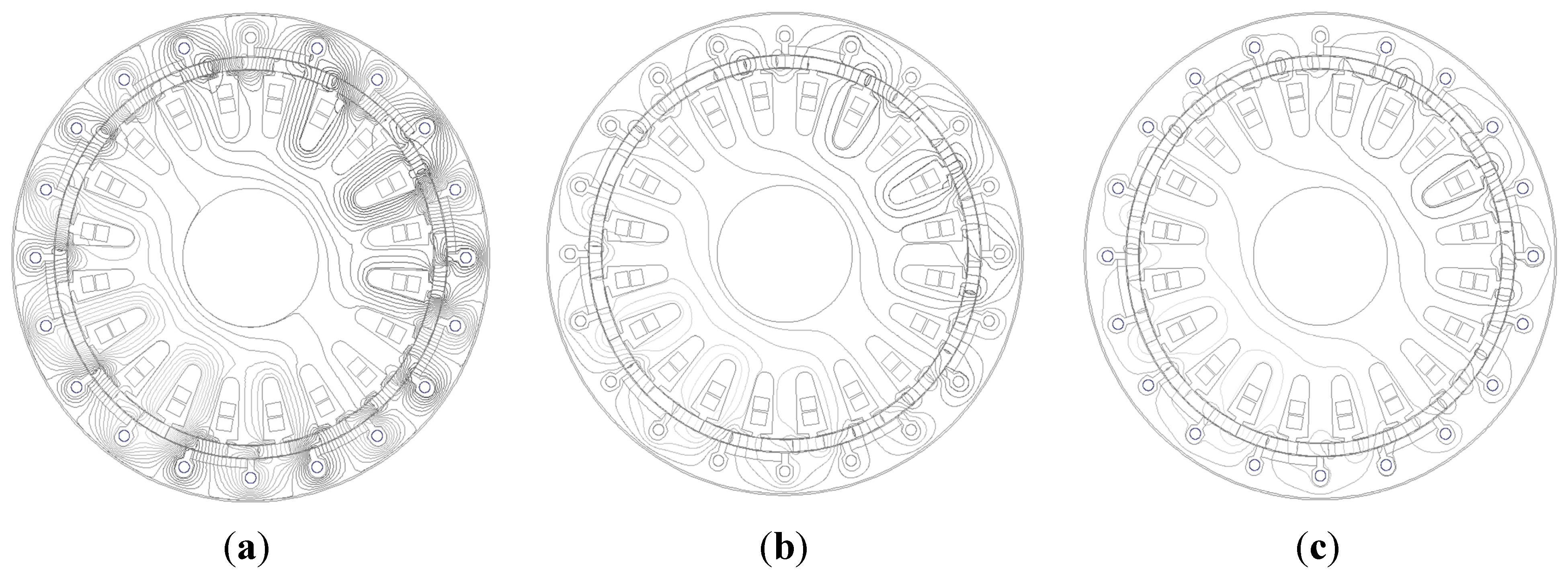
When the power switches S1 and S4 are turned on, a magnetizing current is produced, while when the power switches S2 and S3 are turned on, a demagnetizing current is generated. According to the magnitudes of magnetizing/demagnetizing current pulses, the magnetization level can be divided into three groups, which is a full level using a magnetizing magnetomotive force (MMF) of 2000 A-turns, then a half level using a demagnetizing MMF of 600 A-turns and a weak level using a demagnetizing MMF of 1000 A-turns. Firstly, the magnetic field distributions of the proposed FTFM machine under different magnetization levels are investigated, as shown in Figure 6.
Figure 6. No-load magnetic field distributions of the fault-tolerant flux-modulated memory (FTFM) machine at different magnetization levels: (a) Full level; (b) half level; (c) weak level.
Energies 08 08069 g006
From Figure 6, one can see clearly that the magnetic flux line distribution is densest when a magnetizing current (+2000 A-turns) is applied, and it becomes sparsest when a demagnetizing current (−1000 A-turns) is applied. This phenomenon is especially significant in the outer stator and reflects a good field regulating effect. The corresponding air-gap flux density distributions in the air-gap are shown in Figure 7, illustrating that an air-gap flux regulation range of 2.5-times can be realized. Since all of the PMs are magnetized in the same direction, the flux density waveforms are not symmetrical.
Figure 7. Air-gap flux density distribution under different magnetizing level: (a) Inner air-gap; (b) outer air-gap.
Energies 08 08069 g007
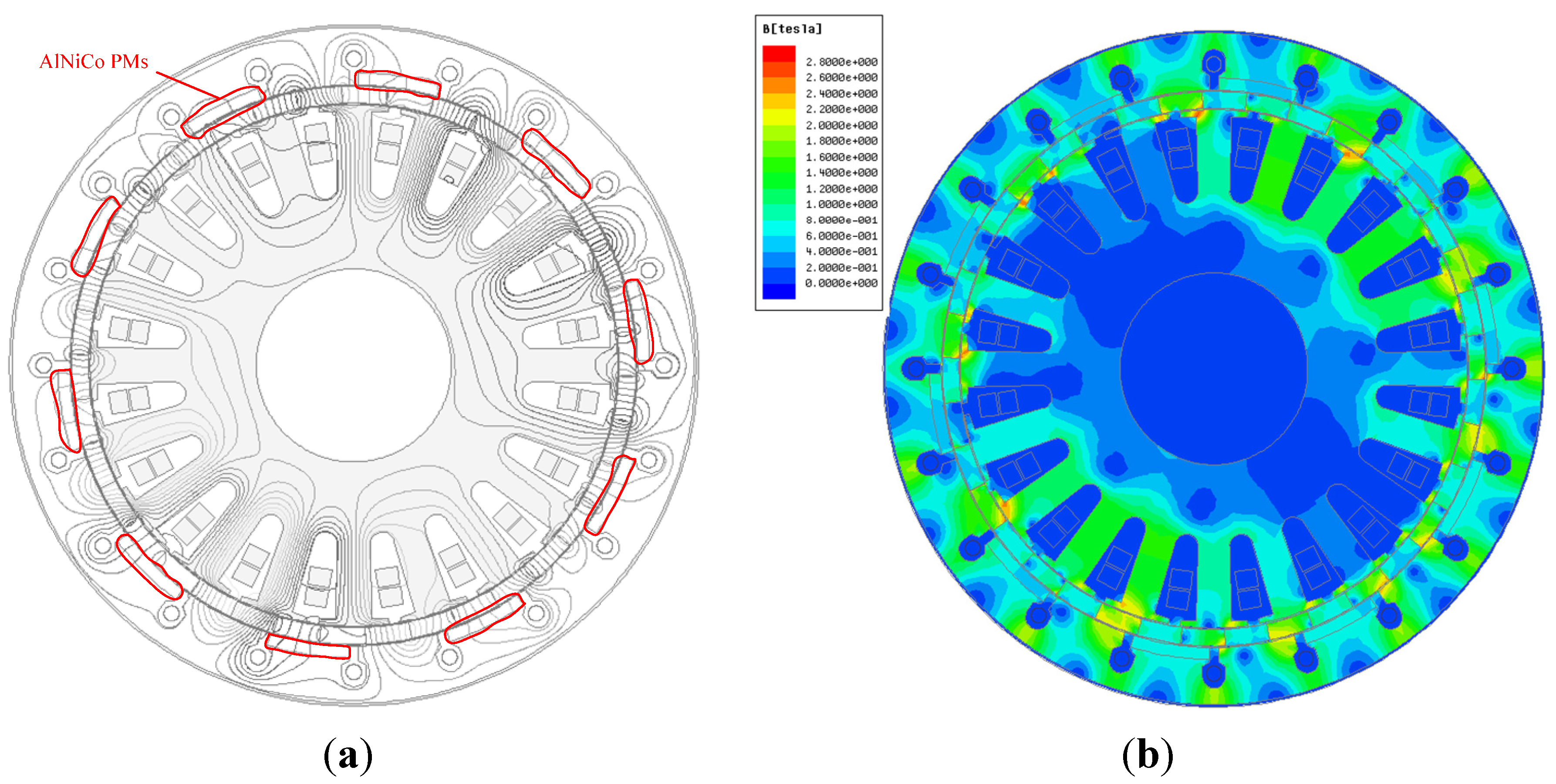
The flux line distribution excited by the full load AC current and rotor PMs is studied, as shown in Figure 8a, in which the AlNiCo PMs are replaced with air during simulation. It can be seen that only very few flux lines pass through the area of AlNiCo PMs; most of the flux lines pass through the outer stator teeth instead; as the reluctance of AlNiCo PMs is much larger than the stator teeth. Therefore, the AlNiCo PMs will not be demagnetized by the armature reaction field during the machine operation. The full load flux density distribution is also investigated as shown in Figure 8b.
Figure 8. Flux line distribution and flux density distribution. (a) Flux line excited by the full load AC current and rotor PMs; (b) flux density distribution at full load.
Energies 08 08069 g008
Figure 9a shows the torque-angle characteristics of the proposed machine with and without flux control when excited with a 40-A sinusoidal and balanced AC current. One can see a clear regulation effect on the torque. The maximum torque reaches 157 Nm when applied with a magnetizing current of +2000 A-turns. The maximum transmitted torque with the same current when the machine runs at the rated speed of 500 rpm are shown in Figure 9b, and the torque ripple is 6.64 Nm, 4.66 Nm and 5.1 Nm, corresponding to the three magnetizing level, respectively, which is very small compared to the maximum transmitted torque.
Figure 9. Torque characteristic of the proposed machine. (a) Torque-angle waveforms; (b) torque-time waveforms.
Energies 08 08069 g009
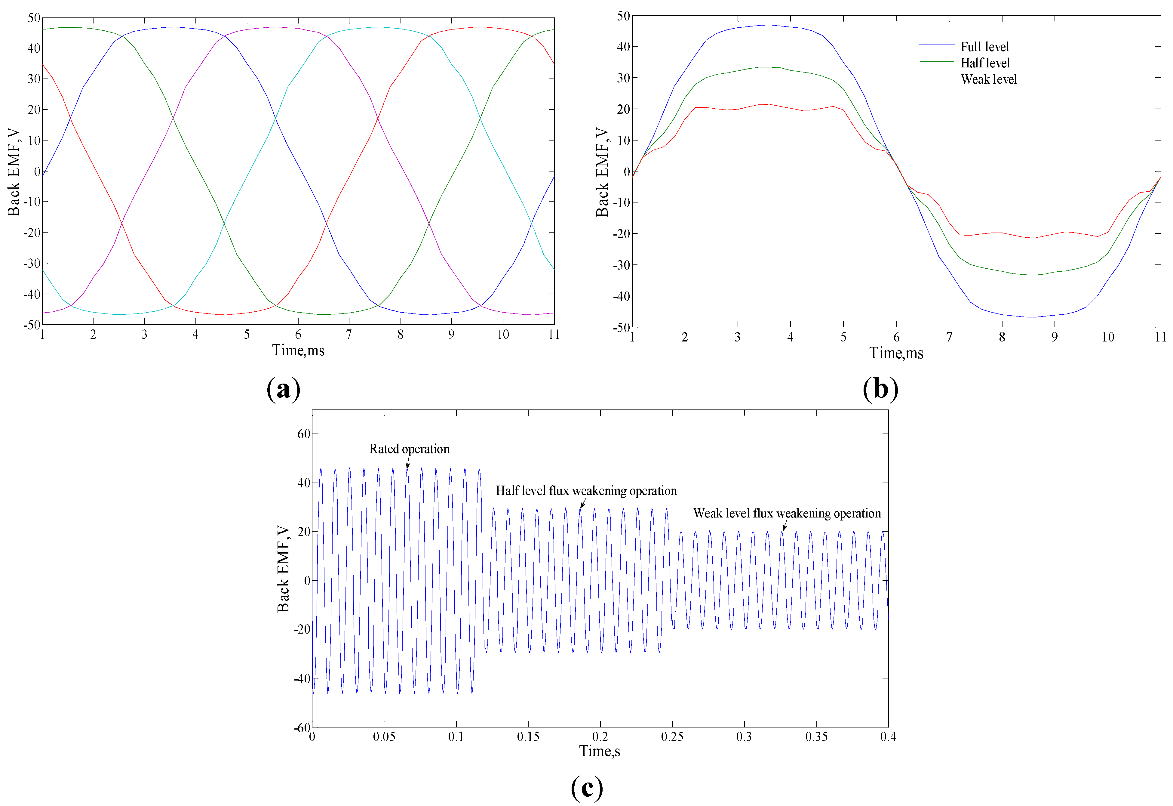
The no-load back electromotive force (EMF) of the proposed FTFM machine without flux control is shown in Figure 10a, and the A-phase back EMF with flux control is shown in Figure 10b, which illustrates that the back EMF can be regulated effectively. Transient analysis of back EMF from rated operation to flux weakening operation is also studied, the transient back EMF of Phase A is depicted and shown in Figure 10c, which also shows a good flux regulating effect.
Figure 10. Back electromotive force (EMF) of the proposed machine. (a) Five-phase back EMF; (b) back EMF of Phase A with flux control; (c) transient back EMF of Phase A.
Energies 08 08069 g010
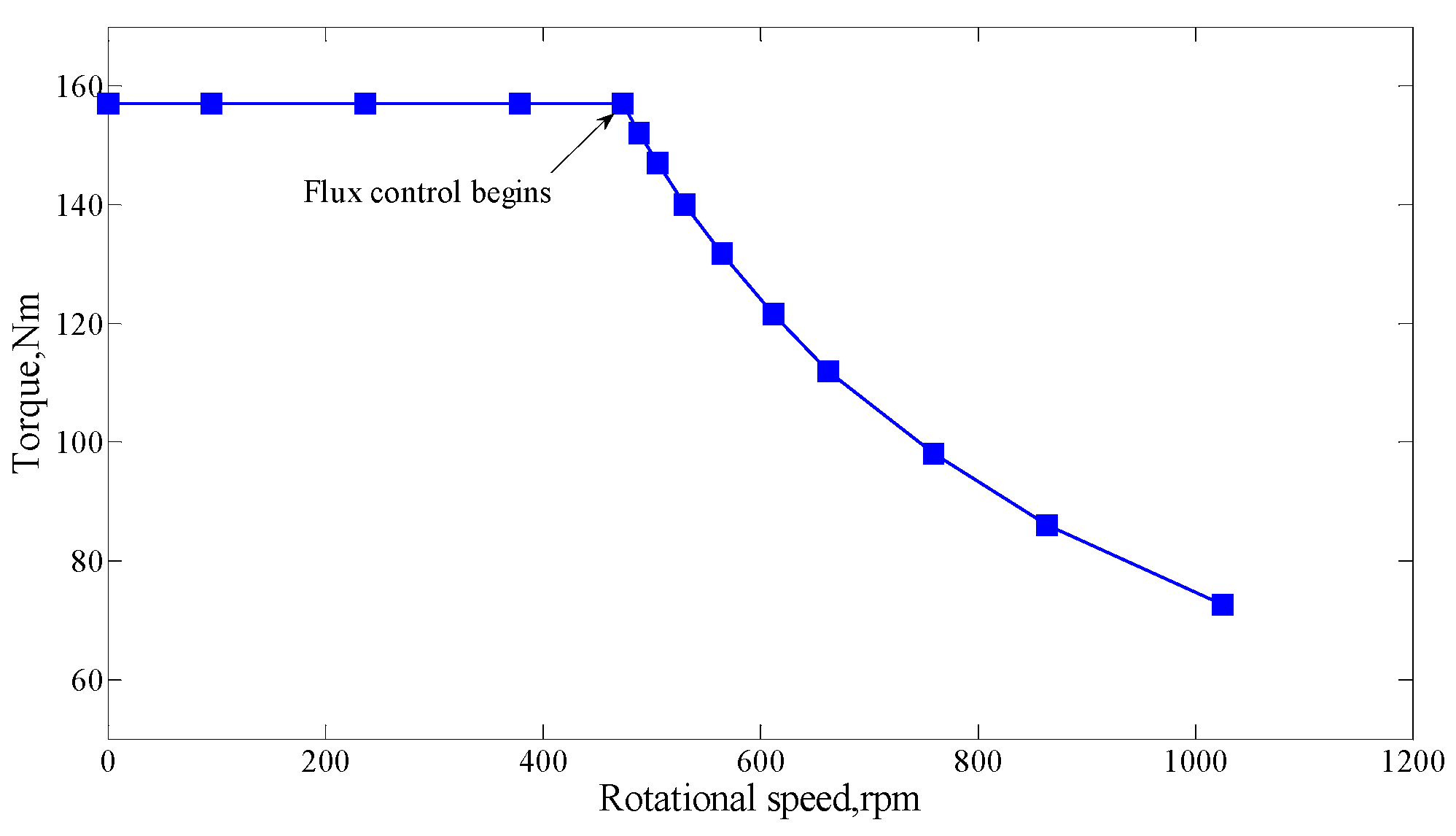
Figure 11 shows the torque-speed characteristic over the whole operating region of the proposed machine. In the low speed region, this machine will work in a constant torque state. As the speed increases, the amplitude of back EMF becomes larger, so flux weakening control is needed to maintain a constant back EMF, and the machine will work in a constant power state.
Figure 11. Torque speed characteristic of the proposed machine.
Energies 08 08069 g011
Furthermore, the machine efficiency is investigated. Since the input power remains unknown during FEM, the efficiency cannot be calculated by dividing the output power with the input power. In this paper, the machine efficiency is calculated by:
η = P output P output + P copperloss + P coreloss
where Pcoreloss refers to the core loss and calculated by FEM. Poutput and Pcopperloss can be computed by:
P output = T ω
P copperloss = N slot ( 2 N ac ) ρ l S slot K / ( 2 N ac )
where T and ω refer to the output torque and angular velocity, Nslot is the slot number, Nac is the number of AC conductors, Sslot is the slot area, K refers to the slot filling factor, and ρ and l represent the resistivity of copper and axial length of AC windings, respectively.
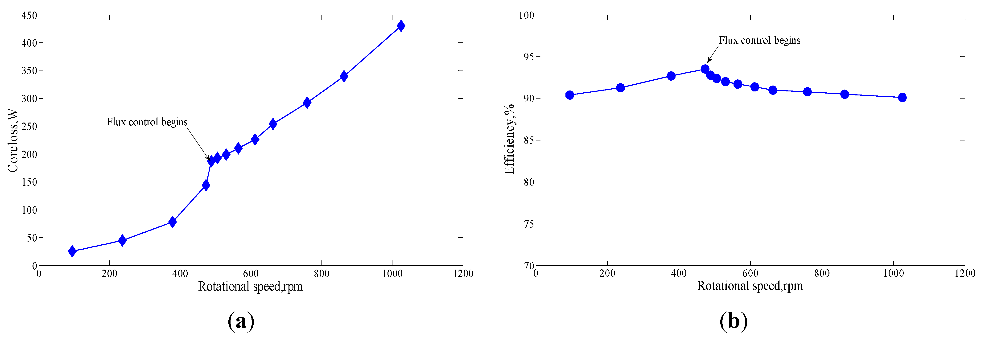
The core losses and machine efficiency are shown in Figure 12. One can see that there is an obvious increase of core loss along with the rotational speed rise. Additionally, this machine enjoys a very high efficiency over 90% in the whole operating region.
Figure 12. Core loss and efficiency of the proposed machine. (a) Core loss; (b) efficiency.
Energies 08 08069 g012

4.2. Fault-Tolerant Analysis

Fault-tolerant capability is one of the most important features of multiphase machines, which means that they can continue to operate in a satisfactory manner even under fault conditions. As the machine output torque is proportional to its interacting field, so the same torque can be maintained as long as the rotating MMF produced by the variations of all five-phase currents keeps unchanged in both time and space.
When one-phase open-circuited (for example, Phase A is open-circuited), to maintain a proper operating condition, the magnetic field produced by the remaining four healthy phases should remain unchanged. The MMF is produced by the remaining four phases:
MMF t ( θ , t ) = MMF b ( θ , t ) + MMF c ( θ , t ) + MMF d ( θ , t ) + MMF e ( θ , t )
For the sake of getting a unique solution and to guarantee that the summation of four current phases is zero, the phase currents are governed by:
i b = i d , i c = i e
and the new phase currents can be expressed as:
{ i a = 0 i b = 1.382 I m cos ( ω t + π 5 ) i c = 1.382 I m cos ( ω t + 4 π 5 ) i d = 1.382 I m cos ( ω t 4 π 5 ) i e = 1.382 I m cos ( ω t π 5 )
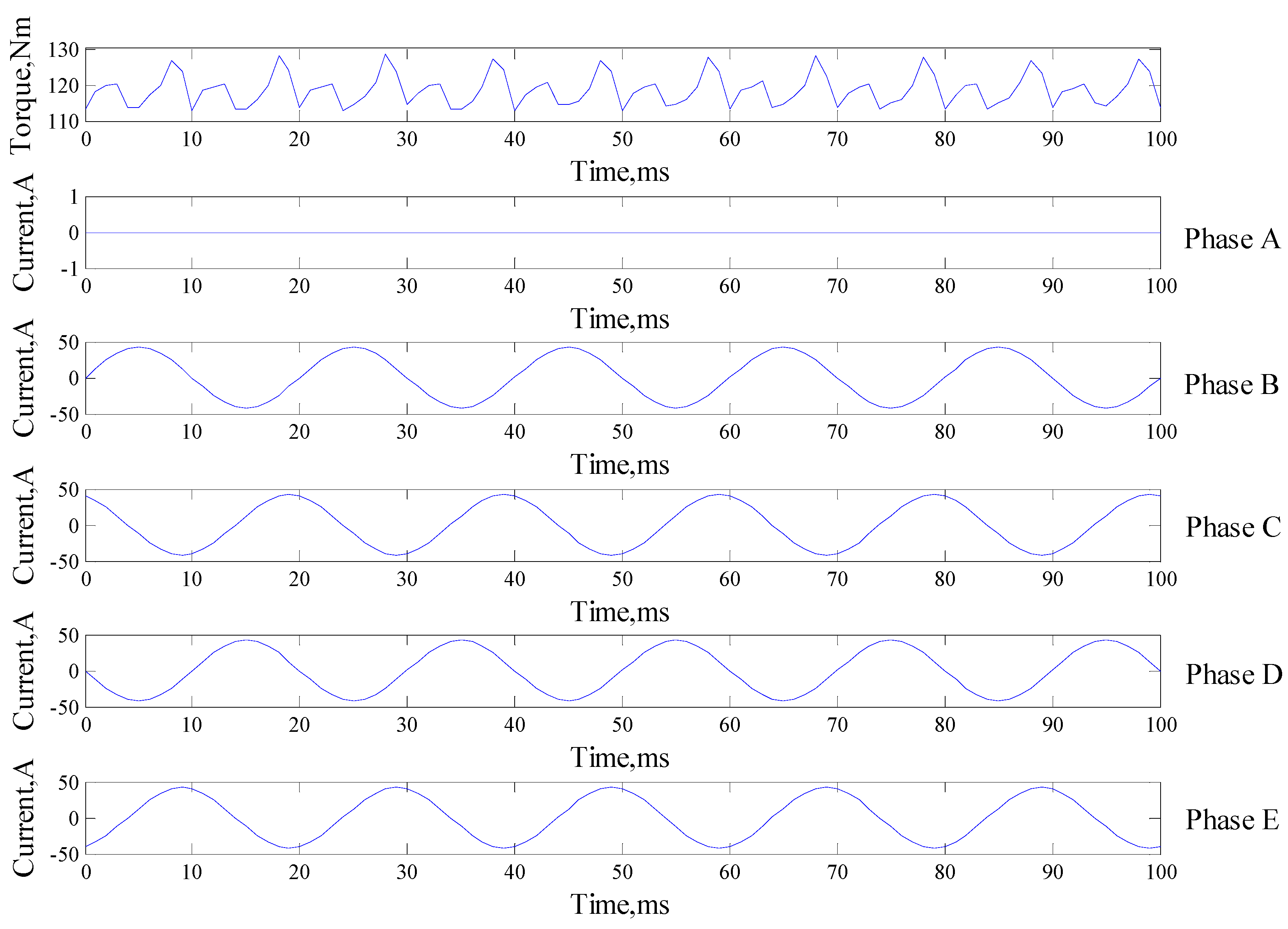
It can be seen that the remediation is to regulate the Phase B current retarded by 36° and the Phase E current advanced by 36°, while keeping the angles of Phase C and Phase D currents unchanged. Furthermore, the current amplitudes of all pf the remaining phases are increased to 1.382-times their pre-fault values. Figure 13 shows the output torque and armature current waveforms at full load when under one-phase open-circuit condition, where we can see that this machine can still output steady torque when one-phase open-circuit, but the torque ripple is relatively higher.
Figure 13. Output torque and armature current waveforms of this machine under one-phase open-circuit condition.
Energies 08 08069 g013
When two adjacent phases open-circuited (for example, both Phase A and Phase B are open-circuited), the MMF will be generated by the remaining three healthy phases:
MMF t ( θ , t ) = MMF c ( θ , t ) + MMF d ( θ , t ) + MMF e ( θ , t )
and the current of the remaining three phases are purposely governed by:
i c + i d + i e = 0
Therefore, the current of the remaining three phases can be expressed as:
{ i c = 2.236 I m cos ( ω t + 2 π 5 ) i d = 3.618 I m cos ( ω t 4 π 5 ) i e = 2.236 I m cos ( ω t )
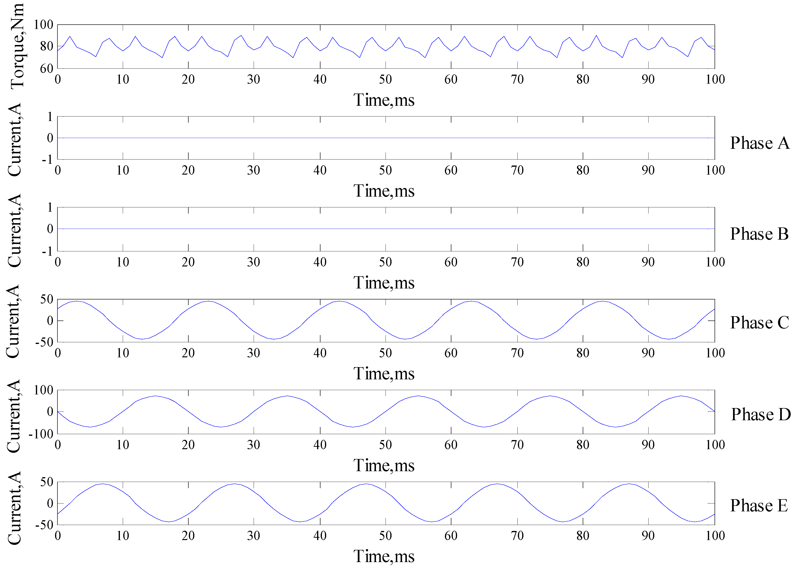
It can be seen that the angles of Phase C and Phase E currents are regulated to that of the pre-fault Phase B and Phase A currents, respectively, while the angle of Phase D current is unchanged. The current amplitudes of Phase C and Phase E are 2.236-times and Phase D is 3.618-times their pre-fault values. The output torque and armature current waveforms when the machine works at full load are shown in Figure 14. Again, we can find that this machine can work well under two-phase open-circuit operation. For the case of two nonadjacent phases open-circuited, the corresponding analysis is similar to that of two adjacent phases that are open-circuited.
Figure 14. Output torque and armature current waveforms of this machine under two-phase open-circuit condition.
Energies 08 08069 g014
The torque characteristic of the proposed machine under fault-tolerant operation are investigated and compared with torque when working at normal conditions, as shown in 
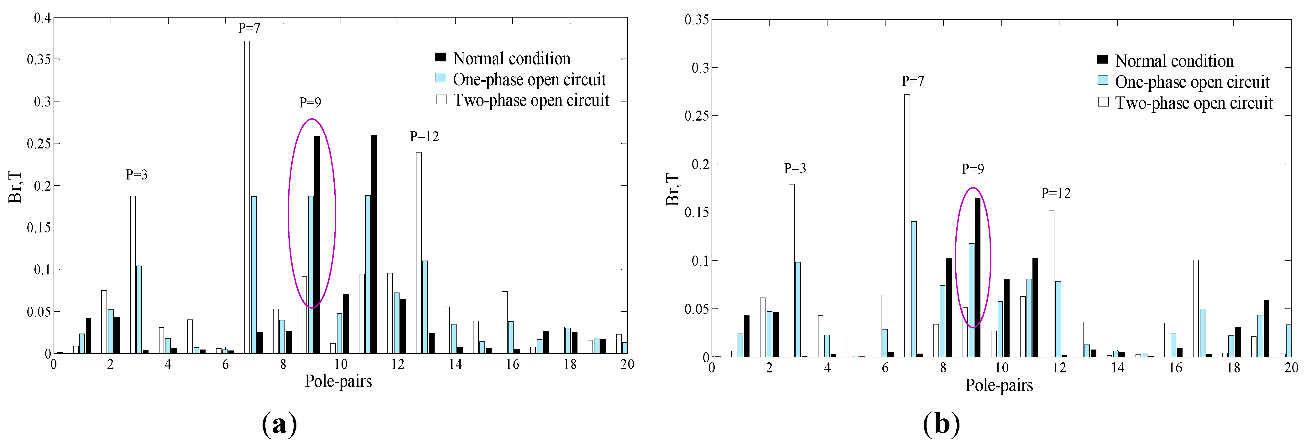
Figure 15, which show that the torque density decreases during fault-tolerant operation; the maximum torque is 157 Nm, 119 Nm and 81 Nm for normal condition, one-phase open circuit condition and two-phase open circuit condition, respectively. However, the torque ripple increases during fault-tolerant operation; the torque ripple is 4.9 Nm 15.8 Nm and 19.5 Nm for these three conditions, respectively. In this proposed machine, the armature windings are designed with nine pole pairs, which will contribute to the average torque; other harmonics will cause the torque ripple. The field harmonics excited only by the armature windings in both normal condition and open circuit conditions are investigated, as shown in Figure 16. One can see clearly that the dominant harmonic in generating average torque with nine pole pairsis weakened during fault-tolerant operation, which leads to the reduction of the torque density; while other harmonics with 3, 7 and 12 pole pairs, which will not contribute to the average torque, but only causes torque ripple, are strengthened during fault-tolerant operation, which is responsible for the increase of the ripple torque when one or two phases open circuit. The electromagnetic performances of the proposed machine are given in Table 2.
Figure 15. Torque characteristic of the FTFM machine at normal condition and fault conditions. (a) Torque-angle waveforms; (b) maximum torque-time waveforms.
Energies 08 08069 g015
Figure 16. Field harmonics excited only by armature windings when working at normal condition and fault conditions. (a) Inner air-gap; (b) outer air-gap.
Energies 08 08069 g016
Table 2. Machine parameters.
ItemsValue ItemsValue
Power (kW)7.8 Maximum torque (Nm)157
Rated speed (rpm)500Maximum torque when one-phase open-circuited (Nm)119
Efficiency>90%Maximum torque when two-phase open-circuited (Nm)81

5. Conclusions

This paper presents a novel fault-tolerant flux-modulated memory PM machine. By using consequent-pole PMs on both the rotor and the outer stator, this machine can realize bi-directional field modulation, which is the foundation to ensure the effective magnetic coupling and flux regulation in the air-gap. Hence, the proposed machine can enjoy a large torque density, and a torque density of 32 kNm/m3 can be achieved. The magnetic flux consists of magnetic fields excited by the two sets of PMs and those excited by the armature windings. The air-gap flux density can be regulated readily by applying a temporary DC current pulse with negligible excitation loss; hence, the machine operating region can be expanded, and the machine efficiency is also improved. The fault-tolerant capabilities of the proposed machine are studied in detail. The results shows that this machine can maintain a high efficient operation state under open-circuit situations.

Acknowledgments

This work was supported by research grants (Project PolyU 5388/13E and PolyU 152130/14E) of the Research Grants Council in the Hong Kong Special Administrative Region, China.

Author Contributions

Shuangxia Niu conceived of the idea of the research and provided guidance and supervision. Qingsong Wang implemented the research, performed the analysis and wrote the paper. All authors have contributed significantly to this work.

Conflicts of Interest

The authors declare no conflict of interest.

References

  1. Han, S.; Cui, S.; Song, L.; Chan, C. Electromagnetic analysis and design of switched reluctance double-rotor machine for hybrid electric vehicles. Energies 2014, 7, 6665–6688. [Google Scholar] [CrossRef]
  2. Li, Y.; Zhao, J.; Chen, Z.; Liu, X. Investigation of a five-phase dual-rotor permanent magnet synchronous motor used for electric vehicles. Energies 2014, 7, 3955–3984. [Google Scholar] [CrossRef]
  3. Sui, Y.; Zheng, P.; Wu, F.; Yu, B.; Wang, P.; Zhang, J. Research on a 20-slot/22-pole five-phase fault-tolerant pmsm used for four-wheel-drive electric vehicles. Energies 2014, 7, 1265–1287. [Google Scholar] [CrossRef]
  4. Vidal, Y.; Acho, L.; Luo, N.; Zapateiro, M.; Pozo, F. Power control design for variable-speed wind turbines. Energies 2012, 5, 3033–3050. [Google Scholar] [CrossRef]
  5. Yan, Y.; Wang, M.; Song, Z.F.; Xia, C.L. Proportional-resonant control of doubly-fed induction generator wind turbines for low-voltage ride-through enhancement. Energies 2012, 5, 4758–4778. [Google Scholar] [CrossRef]
  6. EL-Refaie, A.M.; Jahns, T.M. Optimal flux weakening in surface pm machines using concentrated windings. In Proceedings of the Conference Record of the 2004 IEEE Industry Applications Conference, 39th IAS Annual Meeting, Seattle, WA, USA, 3–7 October 2004; pp. 1038–1047.
  7. Kim, J.M.; Sul, S.K. Speed control of interior permanent magnet synchronous motor drive for the flux weakening operation. IEEE Trans. Ind. Appl. 1997, 33, 43–48. [Google Scholar]
  8. Chau, K.; Li, Y.; Jiang, J.; Liu, C. Design and analysis of a stator-doubly-fed doubly-salient permanent-magnet machine for automotive engines. IEEE Trans. Magn. 2006, 42, 3470–3472. [Google Scholar] [CrossRef]
  9. Yu, C. Design, Analysis and Control of Flux-Mnemonic Permanent Magnet Brushless Machines. Ph.D. Thesis, The University of Hong Kong, Pokfulam, Hong Kong, China, 2010. [Google Scholar]
  10. Li, F.; Chau, K.; Liu, C.; Zhang, Z. Design principles of permanent magnet dual-memory machines. IEEE Trans. Magn. 2012, 48, 3234–3237. [Google Scholar] [CrossRef] [Green Version]
  11. Atallah, K.; Calverley, S.; Howe, D. Design, analysis and realisation of a high-performance magnetic gear. IEE Proc. Electr. Power Appl. 2004, 151, 135–143. [Google Scholar] [CrossRef]
  12. Peng, S.; Fu, W.; Ho, S. A novel high torque-density triple-permanent-magnet-excited magnetic gear. IEEE Trans. Magn. 2014, 50, 1–4. [Google Scholar] [CrossRef]
  13. Atallah, K.; Howe, D. A novel high-performance magnetic gear. IEEE Trans. Magn. 2001, 37, 2844–2846. [Google Scholar] [CrossRef]
  14. Liu, C.T.; Chung, H.Y.; Hwang, C.C. Design assessments of a magnetic-geared double-rotor permanent magnet generator. IEEE Trans. Magn. 2014, 50, 1–4. [Google Scholar] [CrossRef]
  15. Wang, L.; Shen, J.X.; Luk, P.C.K.; Fei, W.-Z.; Wang, C.; Hao, H. Development of a magnetic-geared permanent-magnet brushless motor. IEEE Trans. Magn. 2009, 45, 4578–4581. [Google Scholar] [CrossRef] [Green Version]
  16. Zhu, X.; Chen, L.; Quan, L.; Sun, Y.; Hua, W.; Wang, Z. A new magnetic-planetary-geared permanent magnet brushless machine for hybrid electric vehicle. IEEE Trans. Magn. 2012, 48, 4642–4645. [Google Scholar] [CrossRef]
  17. Zhu, X.; Cheng, M.; Hua, W.; Zhang, J.; Zhao, W. Design and analysis of a new hybrid excited doubly salient machine capable of field control. In Proceedings of the Conference Record of the 2006 IEEE Industry Applications Conference, 41st IAS Annual Meeting, Tampa, FL, USA, 8–12 October 2006; pp. 2382–2389.
  18. Niu, S.; Ho, S.; Fu, W. A novel stator and rotor dual permanent magnet vernier motor with space vector pulse width modulation. IEEE Trans. Magn. 2014, 50, 805–808. [Google Scholar] [CrossRef]
  19. Liu, C.; Chau, K.; Qiu, C. Design and analysis of a new magnetic-geared memory machine. IEEE Trans. Appl. Supercond. 2014, 24, 1–5. [Google Scholar]

