1. Introduction
The behavior of the gas turbine and its related cycles during frequency drops differs from other popular prime movers, such as steam turbines and hydroelectric units. The difference is due to the fact that the gas turbine output power depends on its rotational speed and it decreases by reduction in the grid frequency. This reduction in the gas turbine output power will lead to larger frequency drops and, consequently, will affect the grid stability [
1]. This issue is more important when the gas turbine is running in island mode or in smart grids with a large capacity of renewable energy, as, in these grids, there is no control over the amount of generated power by solar or wind power units and the grid frequency control would rely on fossil fuels units [
2]. For this reason, the sensitivity of the gas turbine to frequency drops will make it more difficult to control the frequency in these grids. Thus, studying the behavior of the gas turbine and the cycles based on it during frequency drops will be beneficial for research in this field. Although the performance of the gas turbine during frequency drops has been studied in some research [
3,
4], less attention has been devoted to the behavior of the other cycles based on the gas turbine and more research is required in this field.
Single-shaft gas turbines are more popular in the power generation industry due to their simplicity, lower price, and better energy recovery from the exhaust. In single-shaft gas turbines, compressor, turbine and generator are located on the same shaft. Therefore, by reduction in grid frequency, the rotational speed of the turbine and the compressor will also decrease. This reduction in the compressor speed will reduce the air flow through the gas turbine. Consequently, the amount of injectable fuel into the combustion chamber will be limited to protect the turbine components from overheating. However, for a successful frequency recovery, more overfueling is needed and restrictions on the amount of injectable fuel into the combustion chamber will cause a further decline in the frequency. Consequently, the gas turbine would be unable to recover the frequency. This issue is more crucial near full load conditions because of the high temperature of the turbine components, or in sudden load changes where more overfueling is needed to recover the frequency [
5,
6].
Simple cycle gas turbine is based on Brayton cycle, which has a low efficiency. Several modifications have been suggested to improve the performance and efficiency of the gas turbine for power generation applications. Combined cycle and wet cycles, such as steam-injected gas turbine (STIG), are known as the most important of these cycles, which are commercially available. The basic idea of these cycles is to recover the wasted energy from the machine exhaust gases. In the combined cycle, the exhaust energy is transferred to steam in heat recovery steam generator (HRSG) and, then, the steam energy will be converted to the electrical energy in the steam turbine. However, in the STIG cycle, the produced steam in the HRSG is injected into the combustion chamber of the gas turbine to increase the cycle efficiency and output power (
Figure 1). Various features of the combined cycle and STIG cycle have been studied and compared in different studies [
7,
8,
9]. For example, combined cycle has a higher efficiency in comparison to the STIG cycle, but, on the other hand, the STIG cycle is simpler and requires less capital investment. The performance of these cycles during frequency drops has not studied in details and requires more research. This study will be beneficial for power generation operators to purchase and install appropriate units to meet the requirements of their grid and expected frequency excursions.
This paper shows how the combined cycle and the STIG cycle perform during frequency dips. For this purpose, two cycles are both based on the same gas turbine, which means that they both have an equal level of technology (
Table 1) that has been developed, and their performances are compared to each other in different scenarios. Moreover, the cycle’s structural and operational parameters, which affect their performance during frequency drops, are highlighted. All of the simulation has been done when the units are running in island mode, which is known as the most difficult case in grid frequency control.
Figure 1.
Combined cycle (a) and STIG cycle (b).
Figure 1.
Combined cycle (a) and STIG cycle (b).
Table 1.
The sample unit design parameters.
Table 1.
The sample unit design parameters.
| Design Parameters | Combined Cycle | STIC Cycle |
|---|
| Compressor air mass flow (Kg/s) | 138 | 116.9 |
| Pressure ratio | 12.2 | 12.2 |
| Compressor outlet temperature (°C) | 348 | 347 |
| Compressor efficiency (%) | 88.5 | 88.5 |
| Fuel mass flow (Kg/s) | 2.62 | 2.93 |
| Turbine Inlet temperature (°C) | 1097 | 1097 |
| Turbine efficiency (%) | 88 | 88 |
| Exhaust Temperature (°C) | 548 | 563 |
| Exhaust mass flow (Kg/s) | 140.68 | 144.2 |
| Gas turbine output power (MW) | 42.18 | 64.3 |
| Steam mass flow (Kg/s) | 18.7 | 24.4 |
| Drum pressure (bar) | 45.38 | 14 |
| HRSG temperature (Gas side) (°C) | Superheater inlet | 547 | 563 |
| Evaporator inlet | 466 | 464 |
| Economizer inlet | 264 | 202 |
| Economizer outlet | 159 | 124 |
| HRSG temperature (Steam side) (°C) | Superheater outlet | 525 | 541 |
| Superheater inlet | 257 | 195 |
| Evaporator inlet | 254 | 192 |
| Economizer inlet | 60 | 60 |
| Steam turbine output power (MW) | 22.1 | - |
| Net output power (MW) | 64.3 | 64.3 |
| Efficiency (%) | 49 | 43.9 |
| Gas turbine inertia (Kg·m2) | 1354 | 1354 |
| Generator efficiency (Kg·m2) | 2437 | 2437 |
| Steam turbine efficiency (Kg·m2) | 753 | - |
3. Simulation Results and Discussion
To compare the performance of the combined cycle and the STIG cycle during frequency dips, two similar units with the same output power are considered in this work. These two units are developed based on the available data from the GE6b gas turbine and their rated output power is 64 MW at ISO conditions. Due to the available technology level for compressor design and the materials used in turbine blades, the compressor pressure ratio and turbine inlet temperature are considered equal for both of the cycles. Other design variables for these cycles at full load condition are listed in
Table 1. To simulate these cycles, a mathematical model is developed based on physical laws, such as conservation of mass and energy and the characteristics of unit components, such as turbine and compressor maps. The details of this modeling approach for gas turbine [
6,
10], HRSG, and steam turbine [
8] can be found in related references. The physical model along with the necessary control loops are implemented in the MATLAB
®/Simulink environment.
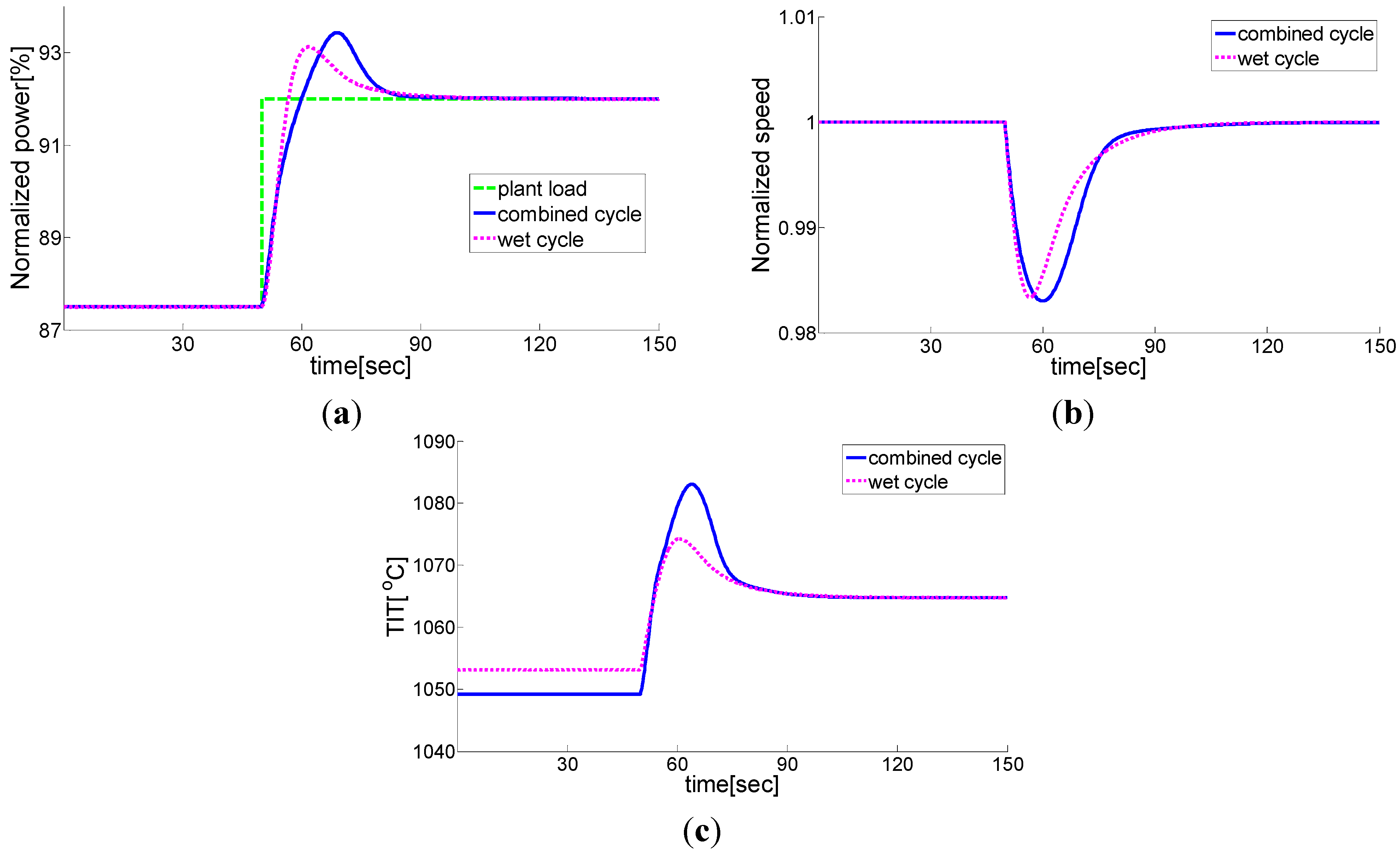
To evaluate and compare the performance of the STIG cycle and the combined cycle, two different scenarios have been considered. In the first scenario, step change load has been applied to both units when they are running in island mode. In these simulations, the speed deviation, which is important from grid point of view, and turbine inlet temperature, which affect the gas turbine component service life, are compared together. The simulation results for different change loads are shown in
Figure 4,
Figure 5 and
Figure 6. The most important results of this simulation can be summarized as follows. For small load changes, combined cycle has a slightly smaller frequency drop in comparison to the STIG cycle. This is because, for small change loads, the inertia of the unit is the most important parameter and the combined cycle has a higher inertia in comparison to the STIG cycle. However, for medium and large change loads, wet cycle frequency drop is smaller than the combined cycle. This is due to the fact that in medium and large loads, the size of frequency drop depends more on the unit response speed than the unit inertia, and since the STIG cycle has more available power during transient maneuvers, its response will be faster in comparison to the combined cycle. On the other hand, although the STIG cycle turbine inlet temperature is higher than the combined cycle in steady state operating condition, except for a certain increase in the injected fuel, the combined cycle turbine inlet temperature increase will be bigger than the STIG cycle’s. Consequently, in a large change load where a large amount of overfueling is required for frequency recovery, the turbine inlet temperature deviation from its steady state operating point will be bigger for the combined cycle. This would result in a faster activation of the temperature control loop for the combined cycle and, as a result, the amount of injectable fuel into the gas turbine combustion chamber will be limited. The limitation in the amount of overfueling makes the unit unstable because the unit cannot provide the load required by the controller. This, in turn, leads to a frequency drop as the unit fails to provide the given load requirement (
Figure 6). The main reason for this phenomenon can be discussed as follows. First of all, the wet cycle working fluid has a higher specific heat capacity. Thus, for certain increases in fuel flow, the combined cycle working fluid will experience a higher temperature rise. Moreover, since only about two-thirds of the combined cycle capacity is available in transient maneuvers, the gas turbine in the combined cycle unit has to produce more power than its steady-state performance to compensate for the required remaining power. Therefore, for the combined cycle, the turbine inlet temperature will be higher than its steady state operating condition.
Figure 4.
Performance of the combined cycle vs. STIG cycle—2.5% step change load (plant loading from 87.5% to 90% of plant load); (a) Normalized power, (b) Normalized speed, (c) Turbine inlet temperature (TIT).
Figure 4.
Performance of the combined cycle vs. STIG cycle—2.5% step change load (plant loading from 87.5% to 90% of plant load); (a) Normalized power, (b) Normalized speed, (c) Turbine inlet temperature (TIT).
Figure 5.
Performance of the combined cycle vs. STIG cycle—4.5% step change load (plant loading from 87.5% to 92% of plant load); (a) Normalized power, (b) Normalized speed, (c) Turbine inlet temperature (TIT).
Figure 5.
Performance of the combined cycle vs. STIG cycle—4.5% step change load (plant loading from 87.5% to 92% of plant load); (a) Normalized power, (b) Normalized speed, (c) Turbine inlet temperature (TIT).
Figure 6.
Performance of the combined cycle vs. STIG cycle—5.1% step change load (plant loading from 87.5% to 92.6% of plant load)—combined-cycle instability limit; (a) Normalized power, (b) Normalized speed, (c) Turbine inlet temperature (TIT).
Figure 6.
Performance of the combined cycle vs. STIG cycle—5.1% step change load (plant loading from 87.5% to 92.6% of plant load)—combined-cycle instability limit; (a) Normalized power, (b) Normalized speed, (c) Turbine inlet temperature (TIT).
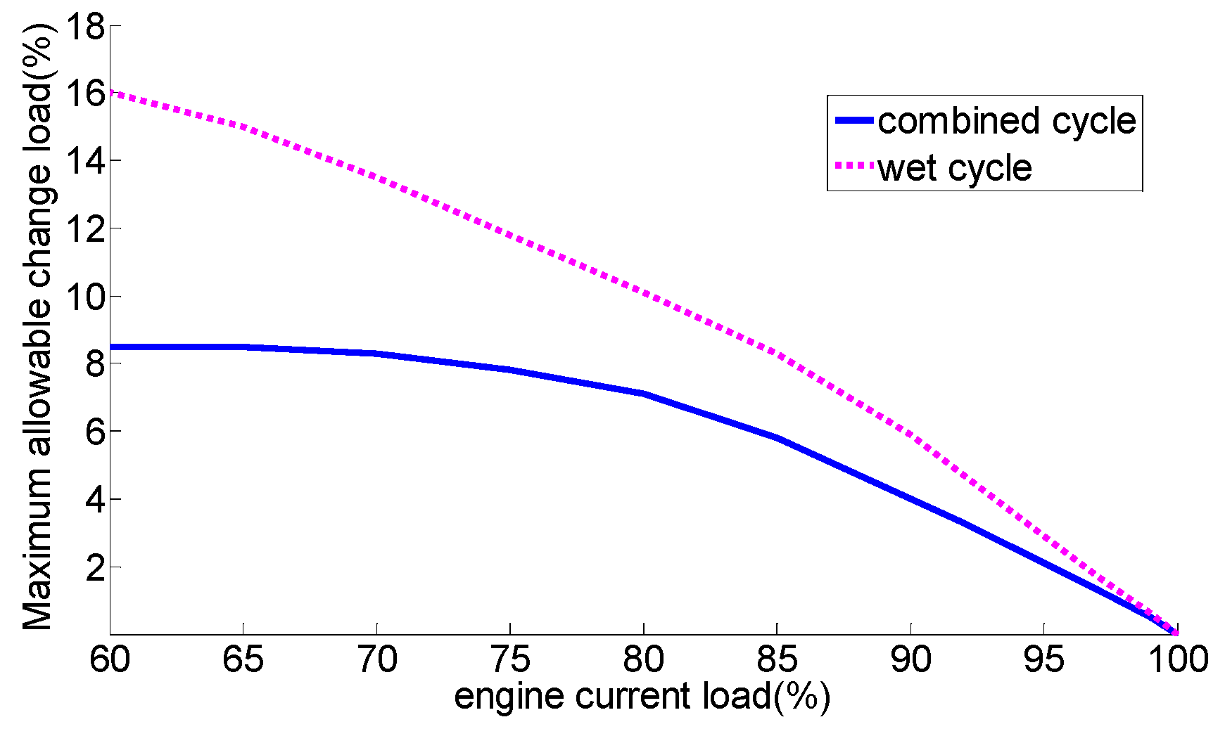
In the second scenario, the maximum tolerable step change load is calculated for the STIG cycle and the combined cycle when they are running in island mode. The results of these calculations at different loads are summarized in
Figure 7. As is shown in this figure, the STIG cycle outperforms the combined cycle in the sudden change loads. This superior performance of the STIG unit is almost twice as good as the similar combined cycle unit in some of the operating conditions, which is very interesting. The main reason for this phenomenon is related to the fact that the wet cycle can use all of its capacity during transient maneuvers and its working fluid has a higher specific heat capacity. It should be noted that the difference between the performance of the combined-cycle and the wet cycle is smaller near full load condition. This is because, at near full load conditions, the unit can experience only small load changes and, therefore, the combined-cycle inertia can compensate for the higher capacity of the wet cycle during transient maneuvers.
Figure 7.
Maximum allowable change load for STIG cycle vs. combined-cycle.
Figure 7.
Maximum allowable change load for STIG cycle vs. combined-cycle.
As the simulation results shows, for small change loads the combined cycle has a better performance in comparison to the wet cycle, and for large change loads the wet cycle would have superior performance in frequency drops. This issue will be beneficial from the point of view that one can design flexible gas turbine units, which can work either on the combined cycle or the wet cycle. Then, the operators can chose between them, according the requirements of their grids and expected frequency excursions. For example, during night, when large change loads are not expected, the unit can work on the combined cycle for a higher efficiency and better performance while, near sunset where a larger change load is expected, the unit can work on the wet cycle for better frequency recovery.


