Article

An Optimal PR Control Strategy with Load Current Observer for a Three-Phase Voltage Source Inverter

1
Department of Electrical Engineering, Southeast University, No. 2 Sipailou, Nanjing 210096, China
2
State Grid Zhejiang Electric Power Research Institute, Hangzhou 310014, China
*
Author to whom correspondence should be addressed.
These authors contributed equally to this work.
Energies 2015, 8(8), 7542-7562; https://doi.org/10.3390/en8087542
Submission received: 14 April 2015 / Revised: 18 June 2015 / Accepted: 15 July 2015 / Published: 24 July 2015
(This article belongs to the Special Issue Smart Metering)

Abstract

:
Inverter voltage control is an important task in the operation of a DC/AC microgrid system. To improve the inverter voltage control dynamics, traditional approaches attempt to measure and feedforward the load current, which, however, needs remote measurement with communications in a microgrid system with distributed loads. In this paper, a load current observer (LCO) based control strategy, which does not need remote measurement, is proposed for sinusoidal signals tracking control of a three-phase inverter of the microgrid. With LCO, the load current is estimated precisely, acting as the feedforward of the dual-loop control, which can effectively enlarge the stability margin of the control system and improve the dynamic response to load disturbance. Furthermore, multiple PR regulators are applied in this strategy conducted in a stationary αβ frame to suppress the transient fluctuations and the total harmonic distortion (THD) of the output voltage and achieve faster transient performance compared with traditional dual-loop control in a rotating dq0 frame under instantaneous change of various types of load (i.e., balanced load, unbalanced load, and nonlinear load). The parameters of multiple PR regulators are analyzed and selected through the root locus method and the stability of the whole control system is evaluated and analyzed. Finally, the validity of the proposed approach is verified through simulations and a three-phase prototype test system with a TMS320F28335 DSP.

Graphical Abstract

1. Introduction

Microgrid is commonly defined as an integrated power system consisting of distributed generators (DGs), distributed energy storages (DSs), and interconnected load, which can operate in grid-connected mode or in intentional islanded mode [1]. To increase the stability of the system, making it more immune to perturbations, such as changes in the loading conditions or changes in the electrical energy production due to environmental variability, the employment of energy storage devices such as a battery have become a solution [2,3].
In the microgrid converter system, power converters operate in different modes, the control techniques of the inverter, which are described in references [4,5], are different from each other. In general, in the grid-connected mode, the control target of the inverter is current or direct power, while in the islanded mode, it is the voltage that the inverter controls, which is analogous to an uninterruptible power supply (UPS) for its local loads [3,6]. This paper will focus on the study of the voltage control of a three-phase inverter.
Various voltage control strategies of a three-phase inverter in the microgrid have been researched. The open-loop control strategy is used in many occasions due to its easy control and good dynamic response [7]. However, the steady-state load voltage may not be compensated to the desired value owing to voltage drop across the filter and the line resistance. To avoid the drawbacks of the open-loop control strategy, a load voltage feedback strategy is adopted in [8]. However, such a single feedback scheme is still inadequate for the bad load regulating characteristic and the poor dynamic response. In [9,10,11], a double feedback control scheme is employed with an inner current loop within an outer voltage loop. The inner current loop can be formed using either the filter inductor current or the filter capacitor current. However, the low frequency disturbance from the load will affect the load voltage performance significantly. In order to improve the performance of the dual-loop control strategy, load current is added into the internal current loop in this paper to enhance the dynamic response and enlarge the stability margin of the control system. Hence, precise information of the load current is required to implement the internal current loop.
Since the load current is under low frequency, a current sensor can be used to measure load current [12,13]. However, these sensors suffer from several practical difficulties. Firstly, a correction algorithm has to be added to compensate for the time-varying bias caused by current sensors, which will increase the complexity of the control system in terms of implementation. Secondly, the use of current sensors requires a very precise and noise-free differential amplifier, which is difficult to realize in an actual experimental system. Furthermore, the use of current sensors is not flexible for the change of terminal load and these sensors are very costly, which contributes to the overall cost of the inverter.
Considering all the fundamental issues regarding the current sensors mentioned above, current senseless techniques are very advantageous in this particular application. In this paper, an observer is proposed to estimate the load current. This observer not only can provide a clean and noise-free estimation of the load current but can also provide a good cost-free solution for this situation. Furthermore, the control strategy of inverters in this paper is based on stationary frame (α-β coordinates). Compared with the control strategy under rotating frame (d-q coordinates) using PARK transformation, the input control signal under α-β coordinates does not need to be decoupled, which makes the control strategy easier to design [14,15,16,17]. However in reference [17], the sinusoidal values make it impossible for traditional PI regulators to track accurately without static error. Furthermore, a series of low frequency harmonics is introduced due to the dead-time of one bridge, a PI regulator cannot eliminate this kind of harmonics. To solve these problems, the proportional resonant (PR) is introduced in the control strategy [18,19]. The static error of signal control at specific frequency points can be totally eliminated because the ideal PR regulator can offer infinite gain at these points. Moreover, compared with a conventional tandem double loop PR control, the proposed control strategy has high precision and a physical property with an extensible and zero loosely coupled characteristic.
As a result, the proposed control strategy chosen in this paper introduces a load current observer and adopts multiple R regulators under α-β coordinates to track the sinusoidal voltage values. It introduces the load current as the feedforward of the internal current loop, which accelerates the regulating rate of the internal current loop, improves the dynamic response of the system effectively, and restrains the influence on the system caused by the load fluctuation. Also, it has an outstanding performance in voltage control, such as fast transient response, few steady-state errors, and harmonic rejection for low THD under various types of loads (i.e., balanced load, unbalanced load and nonlinear load) for the use of multiple R regulators. To confirm the commonality and feasibility of the proposed control approach, simulations and experiments were performed through the Matlab/Simulink software and through an experimental platform with a TMS320F28335 DSP.
The rest of this paper is arranged as follows. Section 2 presents the basic mathematical model of the three-phase inverter, PR regulator and load current observer. Section 3 details the structure of the proposed control strategy and the design parameters of multiple PR regulators. Section 4 shows the results of simulation and the laboratory test of the control strategy. Section 5 concludes the paper and remarks on possible future research.

2. Mathematical Model

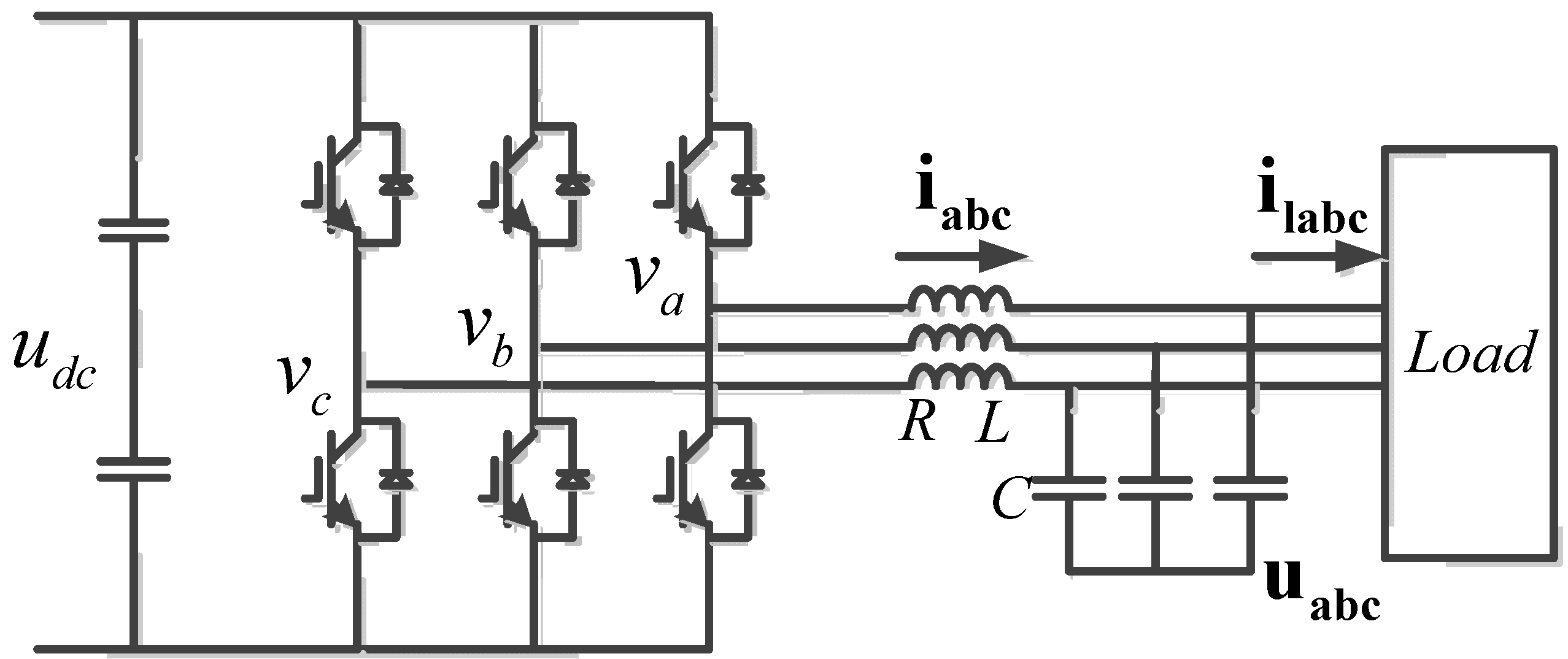
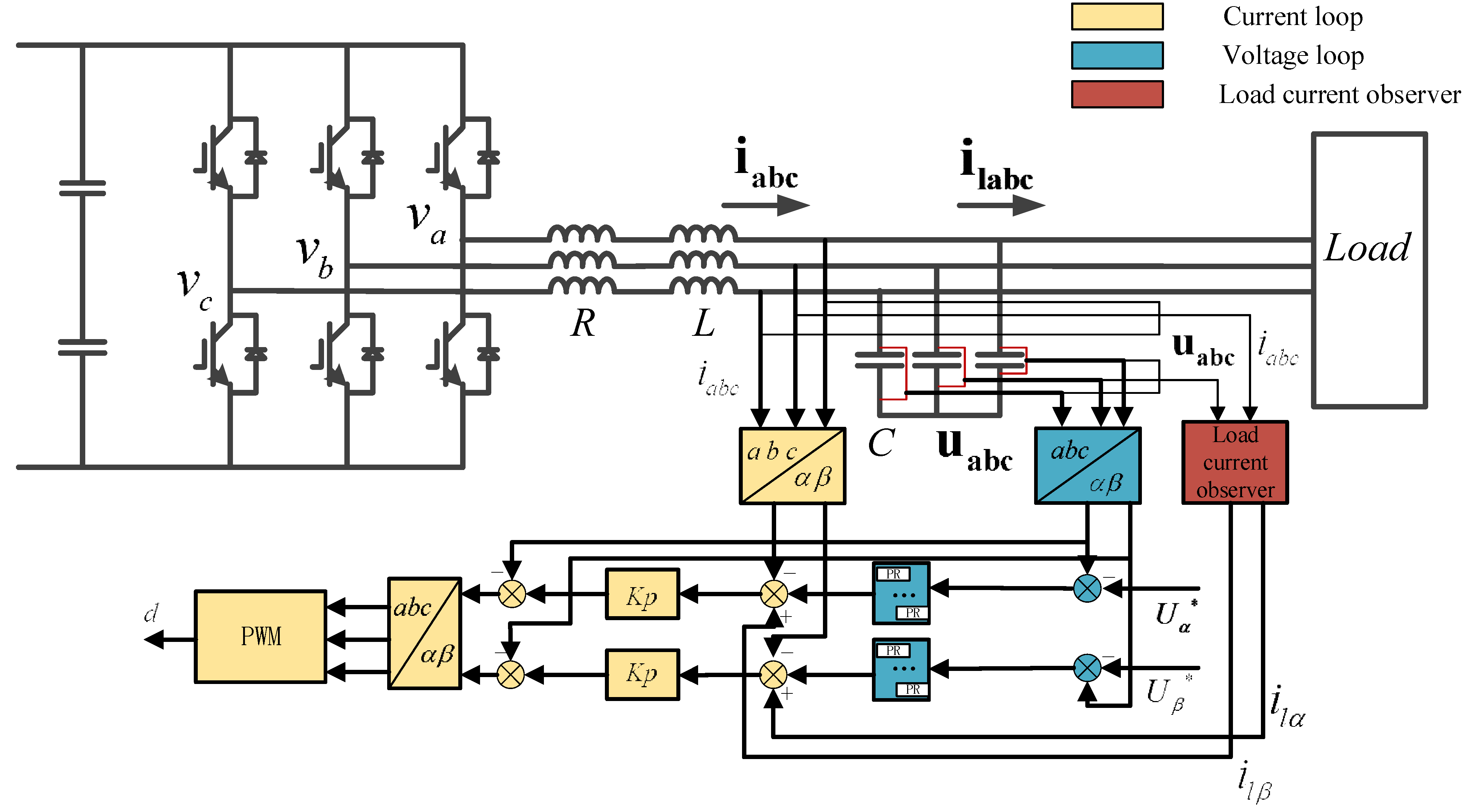
2.1. Model of Three-Phase Inverter

The model of a three-phase inverter can be divided into two categories: one category is based on a synchronous frame system (dq-frame) that usually adopts a PI regulator; another category is built upon a stationary frame system (αβ-frame) that employs the proportional-resonant (PR) regulator.
Figure 1 shows a typical three-phase voltage-source inverter with a RLC filter. The behavior of the circuit can be modeled as follows by applying Kirchhoff’s law:
v a b c u a b c = L d i a b c d t + R i a b c
C d u a b c d t = i a b c i l a b c
where i a b c , u a b c , and i l a b c denote the vectors of the three-phase inductor current, capacitor voltage, and load current, respectively.
Figure 1. Diagram of a three-phase inverter with a RLC output filter.
Energies 08 07542 g001
The aforementioned state Equations (1) and (2) in the stationary abc reference frame can be transformed to the equations in the stationary αβ frame by the Clark Transform:
T 3 s 2 s = 2 3 [ 1 1 2 1 2 0 3 2 3 2 ]
The equation of voltage and current in the stationary αβ frame can be listed as follows:
v α β u α β = L d i α β d t + R i α β
C d u α β d t = i α β i l α β
where, i α β   =   [ i α i β ] T , u α β   =   [ u α u β ] T , i l α β   =   [ i l α i l β ] T , v α β   =   [ v α v β ] T . In consideration of the inexistence of zero sequence components, the expression for zero sequence is removed.
On account of the full symmetry of the α axis and β axis, the analysis and control design can be handled on the α axis independently. Consequently, the model expressed by Equations (4) and (5) can be transformed to the format of the state space:
[ U α U β i α i β ] = [ 0 0 1 C 0 0 0 0 1 C 1 L 0 R L 0 0 1 L 0 R L ] [ U α U β i α i β ] + [ 0 0 1 C 0 0 0 0 1 C 1 L 0 0 0 0 1 L 0 0 ] [ V α V β i l α i l β ]
The control model of the proposed three-phase inverter with an LC output filter in the stationary αβ-frame is illustrated in Figure 2.
Figure 2. Block diagram of control structure of the three-phase inverter.
Energies 08 07542 g002
As can be seen in Equation (6) and Figure 2, the state variables in the α axis have no coupling relation with those in the β axis. Hence, the balanced three-phase PWM inverter can be equal to two independent single-phase PWM inverters after transformation from the abc reference frame to the stationary αβ frame, which indicates that the control strategy of single-phase inverter can also be implemented under the stationary αβ frame. In this way, the design of the controller can be simplified mathematically.

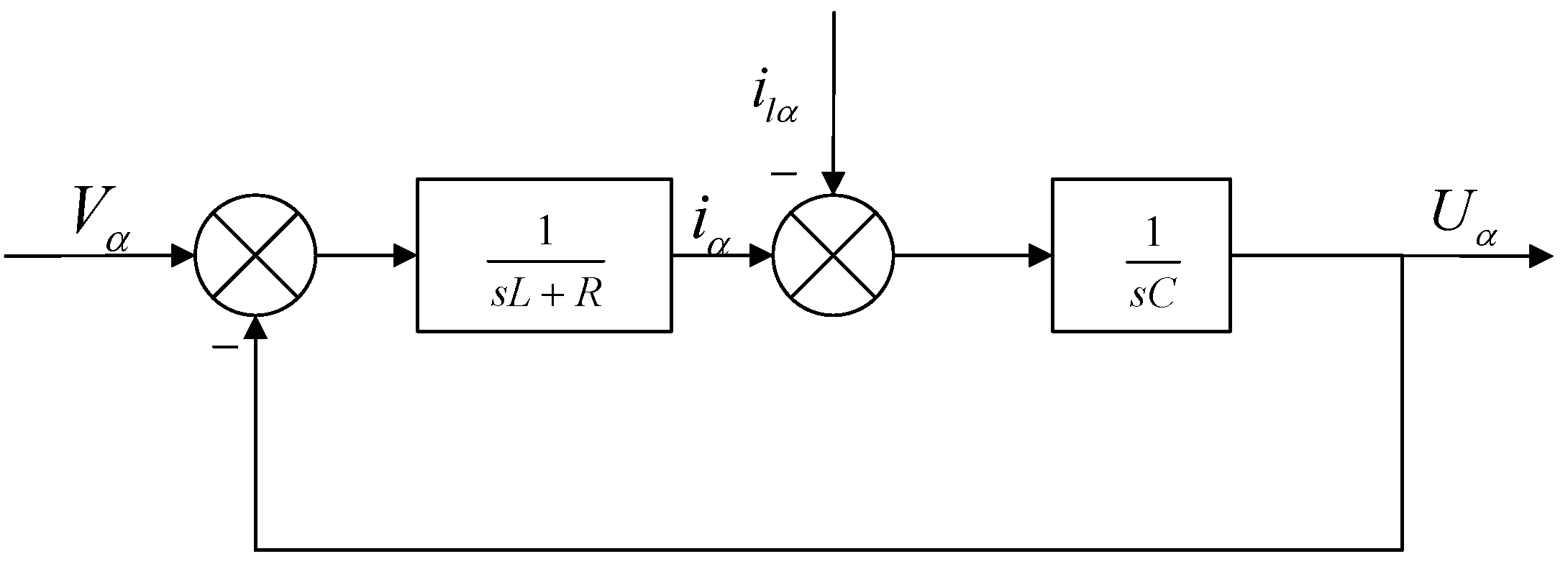
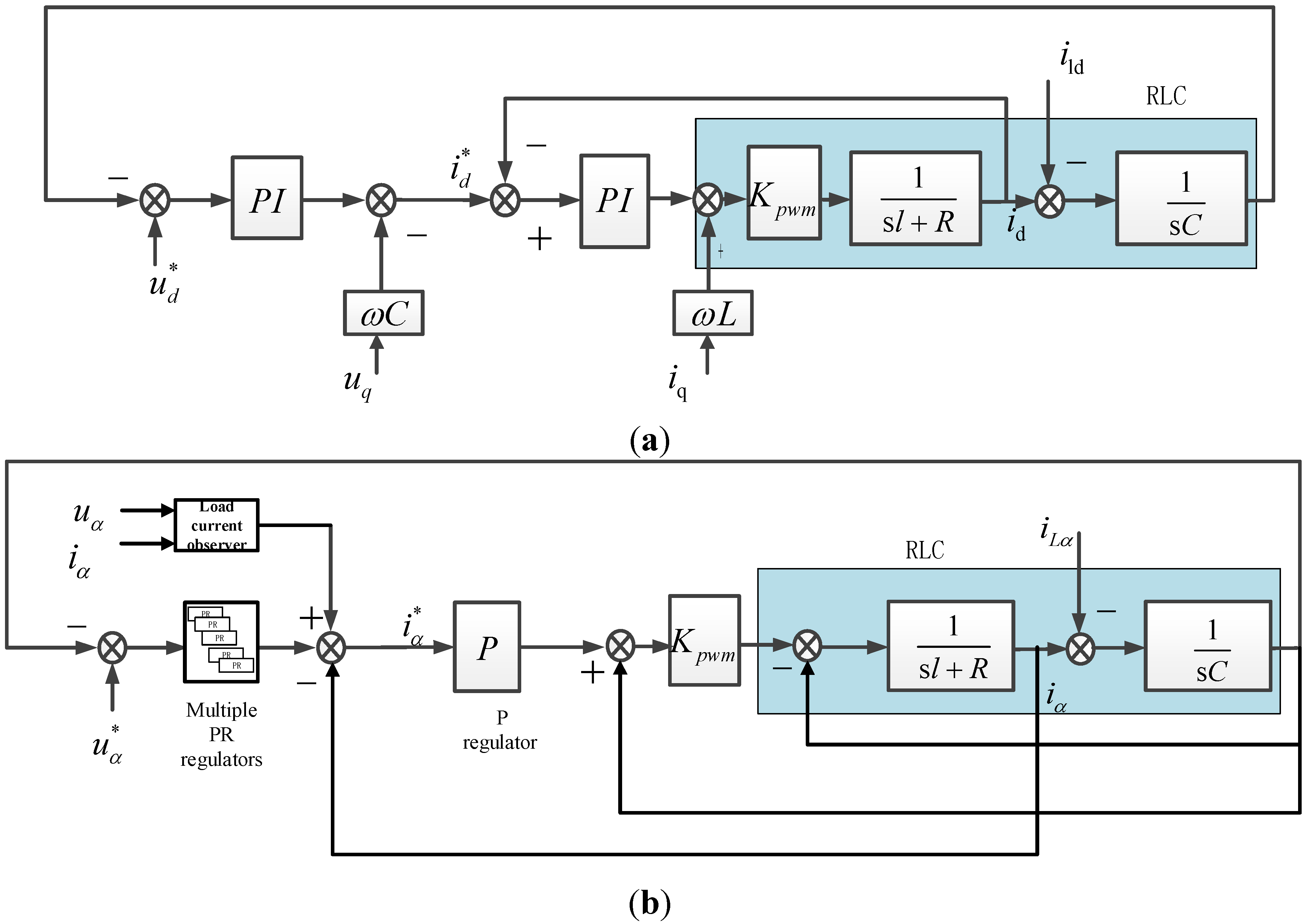
2.2. Model of PR Regulator

According to the internal model principle [20], the best solution for tracking the sinusoidal reference signal and harmonic rejection is the adoption of the PR regulator. An ideal PR regulator has the form as follows:
G P R ( s ) = K p + 2 K i s s 2 + w h 2
where and K p and K i are the proportional and the resonant control gain respectively, w h is the fundamental angular frequency of the source. Figure 3 shows the Bode plot of GPR(s), when K p = 1, K i = 1 and w h = 314 rad/s. It can be seen from Figure 3 that the infinite gain of the ideal transfer function is at the frequency of w h ,is infinite, and there is no phase shift or gain at other frequencies.
Figure 3. Bode diagram of ideal proportional-resonant (PR) regulator.
Energies 08 07542 g003

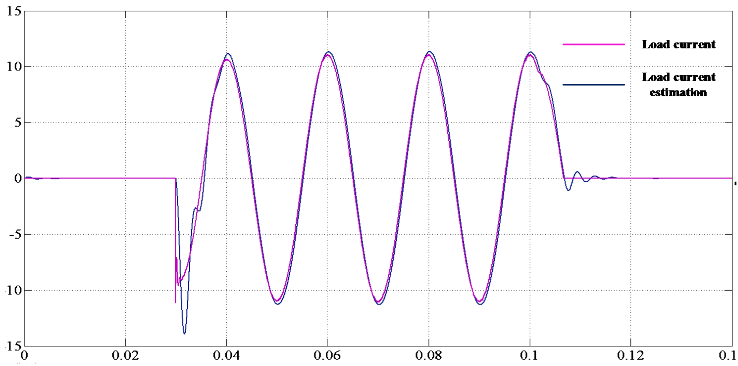
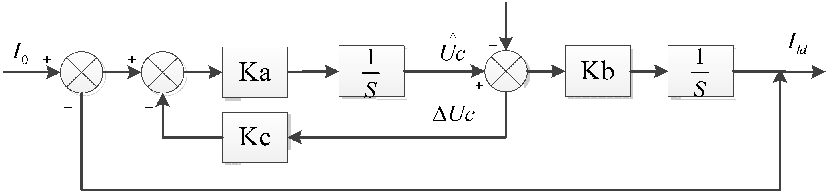
2.3. Model of Load Current Observer (LCO)

Feedforward control of the load current can provide excellent dynamics in three-phase PWM inverter control. However, the situation becomes more complicated and difficult in a common AC bus, feeding multiple inverter devices, in which multiple current sensors and communication channels are required. To obtain the required AC link load current for feedforward signal without adding additional current sensors or communication channels, a feedforward load current is obtained from a second-order current observer.
In the AC link:
C d U c d t = I 0 I l d
where Uc is the voltage of the parallel capacitor, I0 and Ild are the currents of inductor and load respectively.
The discretization of Equation (8) can be expressed as:
{ X = A X + B u y = C X
where: A = [ 0 1 C 0 0 ] , B = [ 1 C 0 ] , C = [ 1 0 ] , X = [ U c I l d ] , X = [ U c I l d ] , y = U c , u = I 0 .
The dynamic equation of state observer based on the Luenberger method can be expressed as:
{ X = A X + B u H ( y y ) y = C X
where X and y are the observer state vector and output respectively. H = [ h 1 h 2 ] T is the observer gain vector.
The block diagram of the state observer derived from Equation (10) is shown in Figure 4.
Figure 4. Block diagram of the state observer.
Energies 08 07542 g004
From Equations (9) and (10):
X X = ( A H C ) ( X X )
The state vector depends only on the initial error and is independent of the input Uc for convergence to a zero state. In order that the vector difference Equation (11) is asymptotically stable, the characteristic equation:
det ( s I ( A H C ) ) = 0
must have all its roots within the unit circle, i.e., | z i | < 1 , i = 1,2,…,m. It is known that if the matrix [ A H C ] yields a stable solution, the error vector will converge to zero from any initial error. Hence, stability is achieved by selecting the observer feedback gain matrix H, so that the roots of the characteristic equation have negative real parts. By expanding and discretizing Equation (10), the observation equation of the load current can be expressed as:
{ U c = 1 C [ I 0 I l d ] h 1 [ U c U c ] I l d = h 2 [ U c U c ]
From the above equation, an alternative expression of LCO in a continuous-time domain is illustrated in Figure 5.
Figure 5. Block diagram of load current observer (LCO).
Energies 08 07542 g005
where, K a = 1 C , K b = h 2 , K c = C h 1 .
Figure 5 clearly shows the physical dynamic process of LCO. The value of C used in the observer can be chosen the same as the physical capacitance of the AC link.
The design of the observer needs to confirm the observer gain H = [ h 1 h 2 ] T so that the roots of the characteristic equation have negative real parts. For the observer being a second order system, the desired characteristic equation is assumed as
det [ λ I ( A H C ) ] = 0
| λ + h 1 1 C h 2 λ | = λ 2 + λ h 1 h 2 C = 0
It is assumed that both of the roots of the characteristic equation are λ 1   =   λ 2   =   k ,   ( k < 0 ) , then
λ 2 + h 1 λ h 2 C = λ 2 2 k λ + k 2
By solving Equation (16), H = [2kCK2].
To illustrate the effectiveness of the designed LCO, the response of the three-phase PWM inverters was simulated with the load in AC link changing. Using the parameters given above, with the capacitance set at 15 uF and a sampling frequency of 12,800 Hz, the simulated performance of the observer is illustrated in Figure 6.
Figure 6. Typical performance of the designed observer.
Energies 08 07542 g006
Since the simulation system is developed to match the actual system very closely, the control parameters can be applied in the experimental voltage control loop. As can be seen in Figure 5, the observer response is still fast enough to estimate the ac link load current with good accuracy and minimum delay.

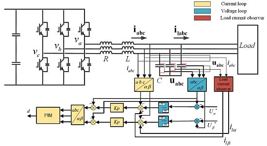
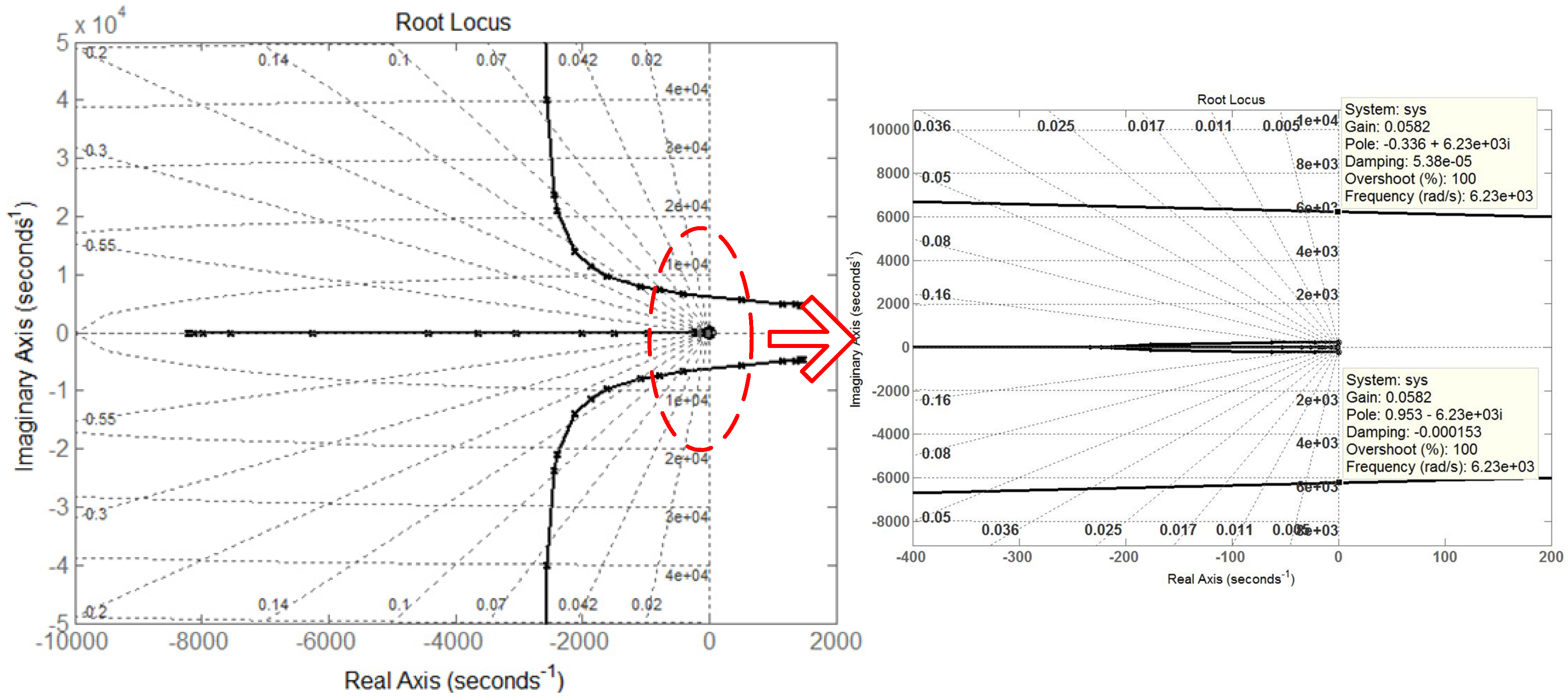
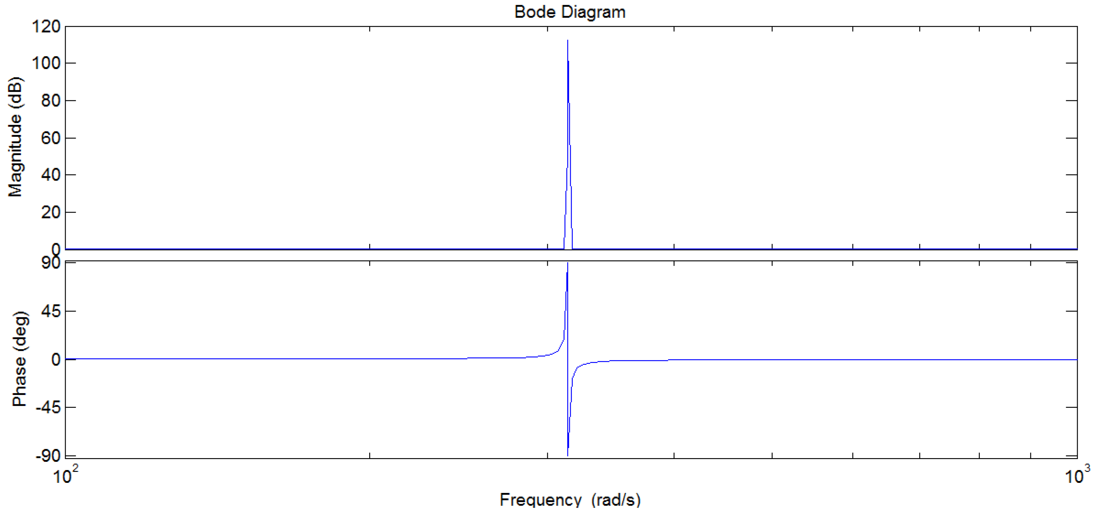
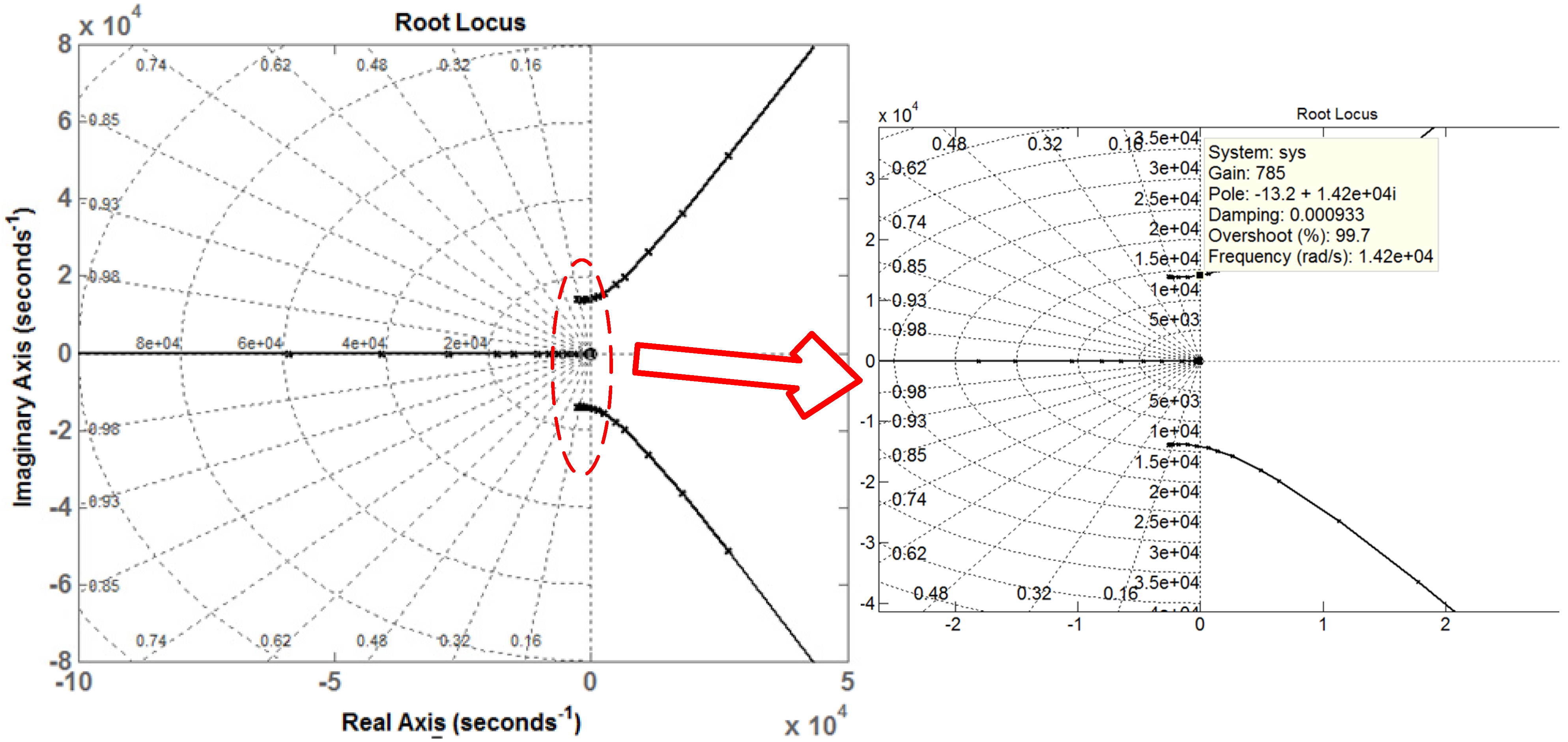
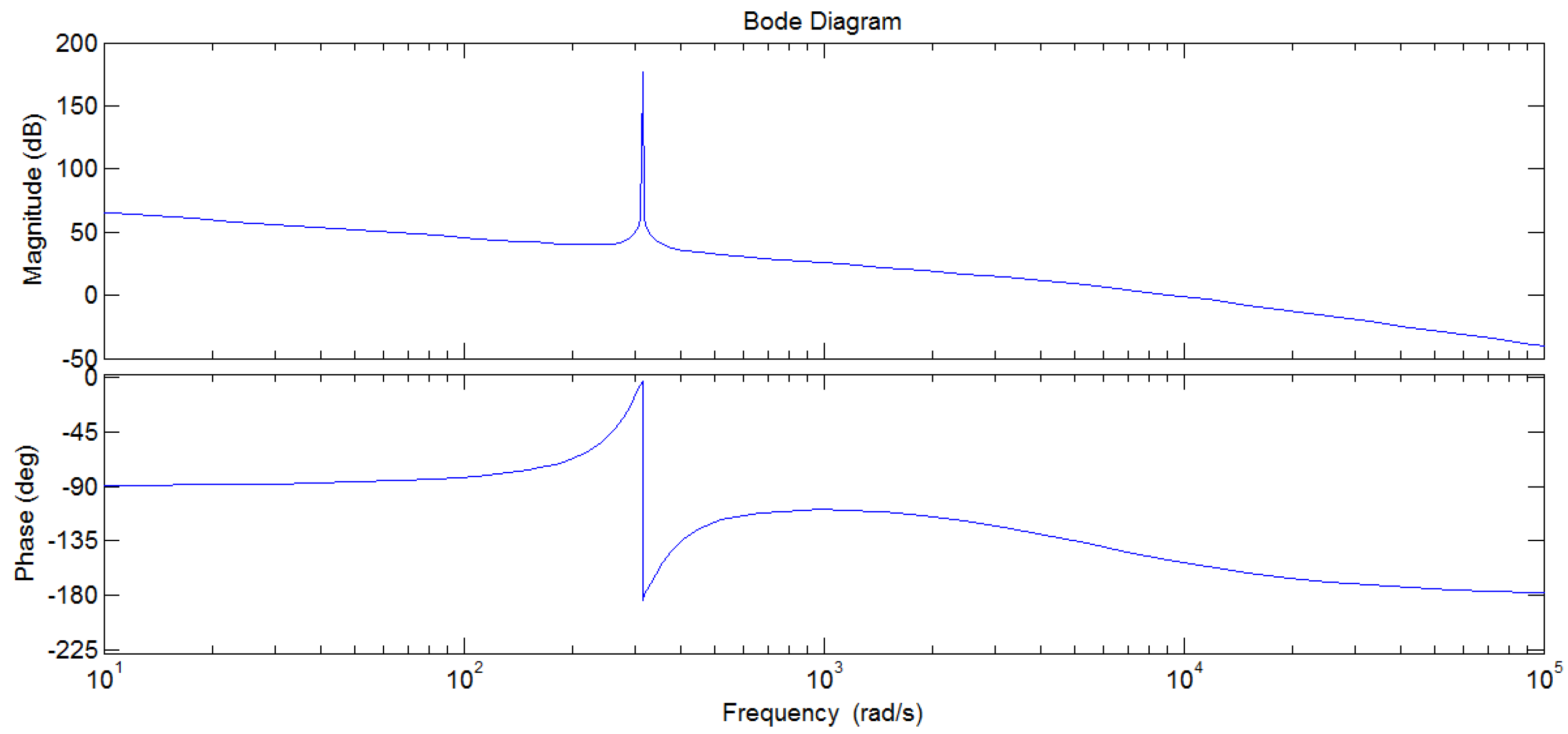
3. Control Structure and Parameters Design

Based on the inverter diagram as shown in Figure 1, the system control strategy under the stationary frame is illustrated in Figure 7.
As shown in Figure 7, the control strategy used in this paper is presented. The output capacitor voltage is regarded as the control target, which is controlled under the stationary frame. The voltage of capacitors is controlled by multiple PR regulators, the output of which is the reference value of the internal current loop. The internal current loop is control by P regulators, after which, the pulse-width-modulation (PWM) module is adopted to generate the drive of IGBT. These five PR regulators are used to mitigate the harmonics with different orders and all of these PR regulators show no effect on each other. Hence, the multiple PR regulators can be considered separately in the system control structure or parameters design, which can make it easier and more effective to analyze the control structure and design control parameters.
The structure of traditional dual-loop control of the inverter, which is based on rotating frame (dq0 coordinates) is shown in Figure 8a. In this control strategy, PI regulators are adopted to track static signals and the input control signal under dq0 coordinates needs to be decoupled. Furthermore, a series of low frequency harmonics is introduced due to the dead-time of one bridge; the PI regulator cannot eliminate this kind of harmonics.
Figure 7. Inverter control system under stationary frame.
Energies 08 07542 g007
Figure 8. Structure of controllers. (a) Traditional inverter controller; (b) The proposed inverter controller with LCO.
Energies 08 07542 g008
In this paper, the controller of inverter is designed as in Figure 8b. Compared with the traditional control strategy, the input control signal under α-β coordinates needs not to be decoupled, which makes the control strategy easier to design. As for aspects of zero steady-state error and anti-interference ability, the PR regulator shows superior performance to the PI regulator. What is more, the PR regulator reduces the harmonic content of the output AC voltage and improves the system performance [21].
As shown in Figure 8b, the output of the LCO, of which the input is capacitor voltage and inductor current in the AC link, acts as the feedforward of the internal current loop of the proposed controller. Considering the independence of every PR regulator of the multiple PR regulators module in mitigating harmonics of output signals, the closed-loop and open-loop transfer functions of the control system, which includes only one PR regulator that regulates the fundamental harmonic, can be deduced as:
G c l ( S )   =   a 0 s 2 + a 1 s + a 2 b 0 s 4 + b 1 s 3 + ( b 2 + a 0 ) s 2 + ( b 3 + a 1 ) s + ( b 4 + a 2 )
G o p ( S )   =   a 0 s 2 + a 1 s + a 2 b 0 s 4 + b 1 s 3 + b 2 s 2 + b 3 s + b 4
where: a 0   =   K p K p w m P , a 1   =   2 K i K p w m P , a 2   =   K p K p w m P w 2 , b 0   =   C L , b 1   =   C R + C K p w m P , b 2   =   C L w 2 + 1 K p w m , b 3   =   w 2 C R + w 2 C K p w m P , b 4   =   w 2 ( 1 K p w m ) .
The open loop transfer function indicates that it is a four-order system and it is complex to choose the proper controller parameters. In order to select the proper parameters, i.e., K p and K i , parameter related root locus of the closed-loop transfer function is adopted in the analysis. By changing one of the parameters each time, the influence of every parameter on the system performance is analyzed [18]. The closed-loop root locus diagrams are shown as follows.
Examples of root locus where K p or K i 1 varies, are illustrated in Figure 9 and Figure 10 respectively. As shown in Figure 9, the poles of the closed-loop transfer function vary with the value of K p while K i 1 = 150 and p = 10 and the dynamic performance of the control strategy keeps stable when K p > 0.0582. Similarly, Figure 10 shows the poles of the closed-loop transfer function varies with the value of K i 1 where K p = 0.3 and p = 10 and the dynamic performance of the control strategy stays stable when K i 1 < 785. It is worth mentioning that the designs of other parameters of 5-multiple PR regulators based on root locus are similar to the given examples.
Figure 9. Diagram of root locus with varying parameter K p while other parameters are maintained constant.
Energies 08 07542 g009
Figure 10. Diagram of root locus with varying parameter K i 1 while other parameters are maintained constant.
Energies 08 07542 g010
Based on the root locus method, the proper parameters of 5-multiple PR regulator are shown in Table 1 and parameters of simulation are shown in Table 2.
Table 1. Parameters of controller.
ParametersValue
K p 0.3
K i 1 150
K i 2 100
K i 3 20
K i 4 80
K i 5 5
P15
Table 2. Parameters of simulation.
ParametersValue
DC-link voltage U d c 700 V
Output voltage U a b c 220 V
Output frequency f 50 Hz
Switching and Sampling frequency f s 12,800 Hz
Output Filter R0.5 Ω
Output Filter L2 mH
Output Filter C15 uF
To analyze the stability of the control strategy, the zero-pole distributive chart of the closed-loop transfer function G o p ( S ) is shown in Figure 11. Based on the analysis and the given parameters above, the location of poles and zeros are P1 = −110, P2 = −937, P3,4 = −2100 ± i9500, Z1 = −111, Z2 = −889. The corresponding Bode diagram of the open-loop transfer function G o p ( S ) is shown in Figure 12.
Figure 11. Zero-pole distributive chart of the closed-loop transfer function G o p ( S ) .
Energies 08 07542 g011
Figure 12. Bode diagram of the open-loop transfer function.
Energies 08 07542 g012
As shown in Figure 12, the close-loop transfer function has a gain greater than 150 dB at a frequency of 341 rad/s, which indicates that the static error of signal control at specific frequency (50 Hz) points can be totally eliminated due to the PR regulator introduced for this control strategy.

4. Simulation and Laboratory Experiments

4.1. Simulation Study

A simulation system was established in the MATLAB/SIMULINK environment to verify the effectiveness of the proposed method for LCO based on the αβ frame applied for the control of the voltage source inverter in the microgrid. To comprehensively understand the advantages of the proposed control strategy and the LCO, several pairs of comparison simulation on the proposed control scheme with and without LCO were conducted. The comparison simulation was performed under the following three conditions:
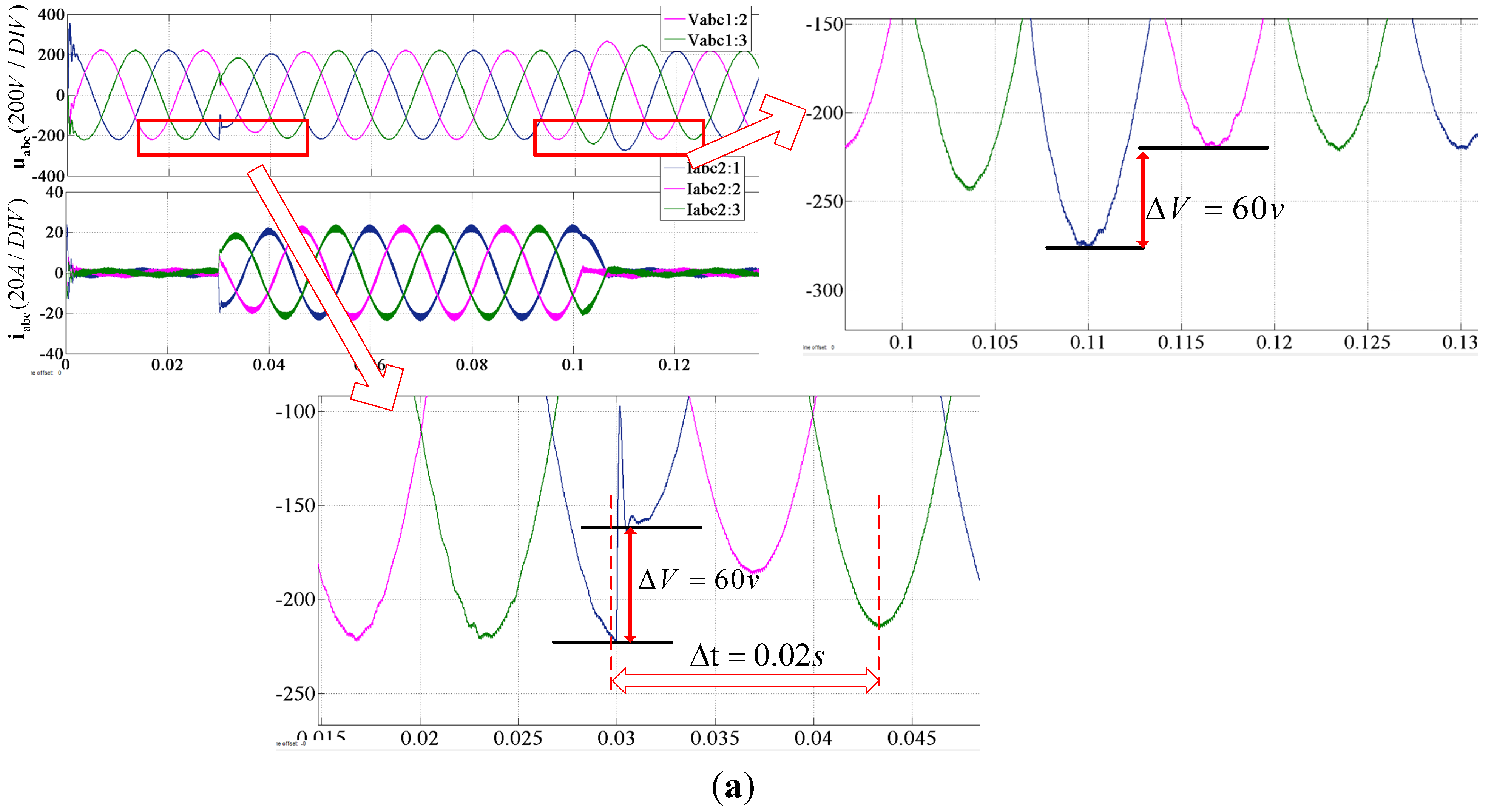
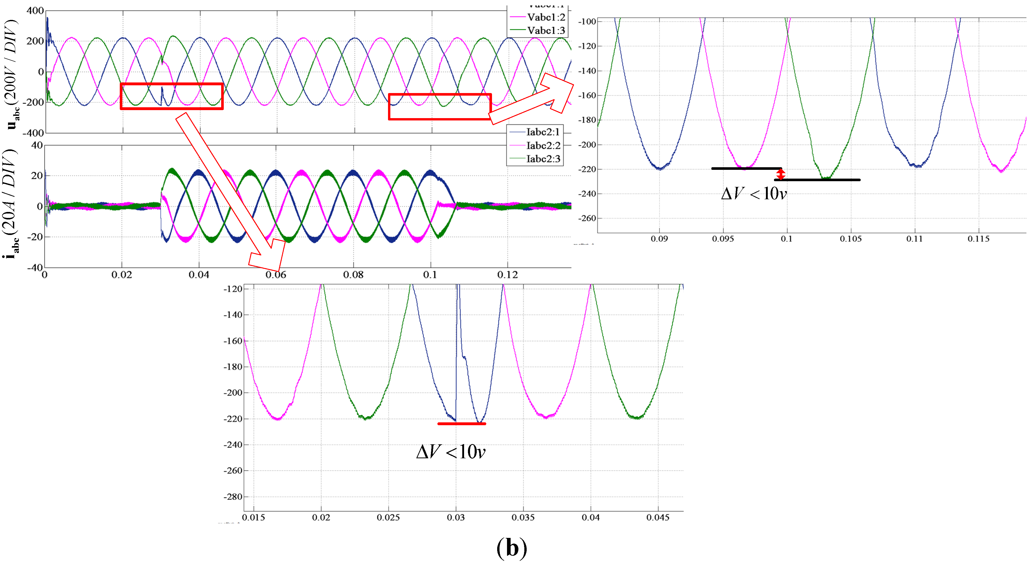
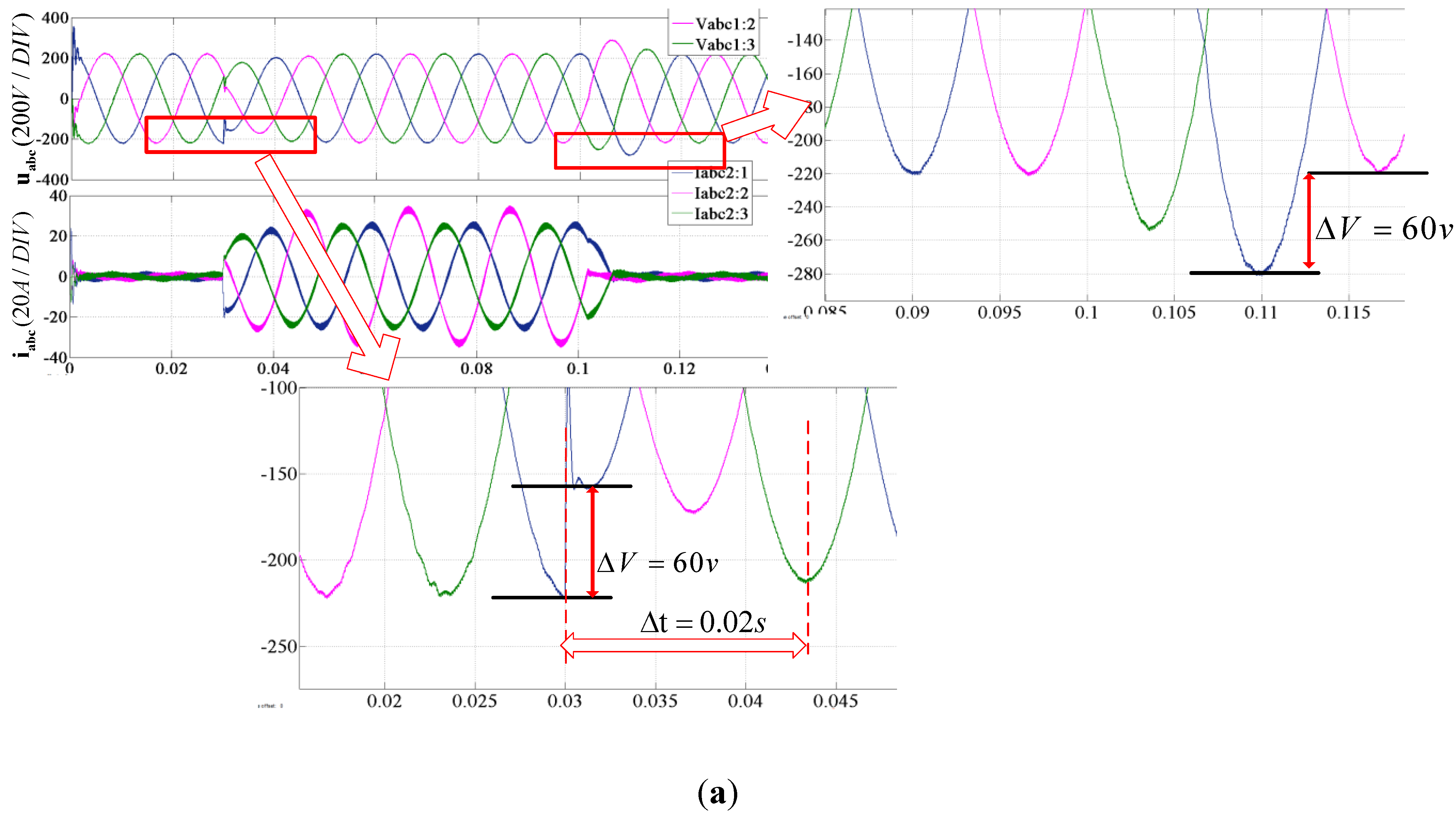
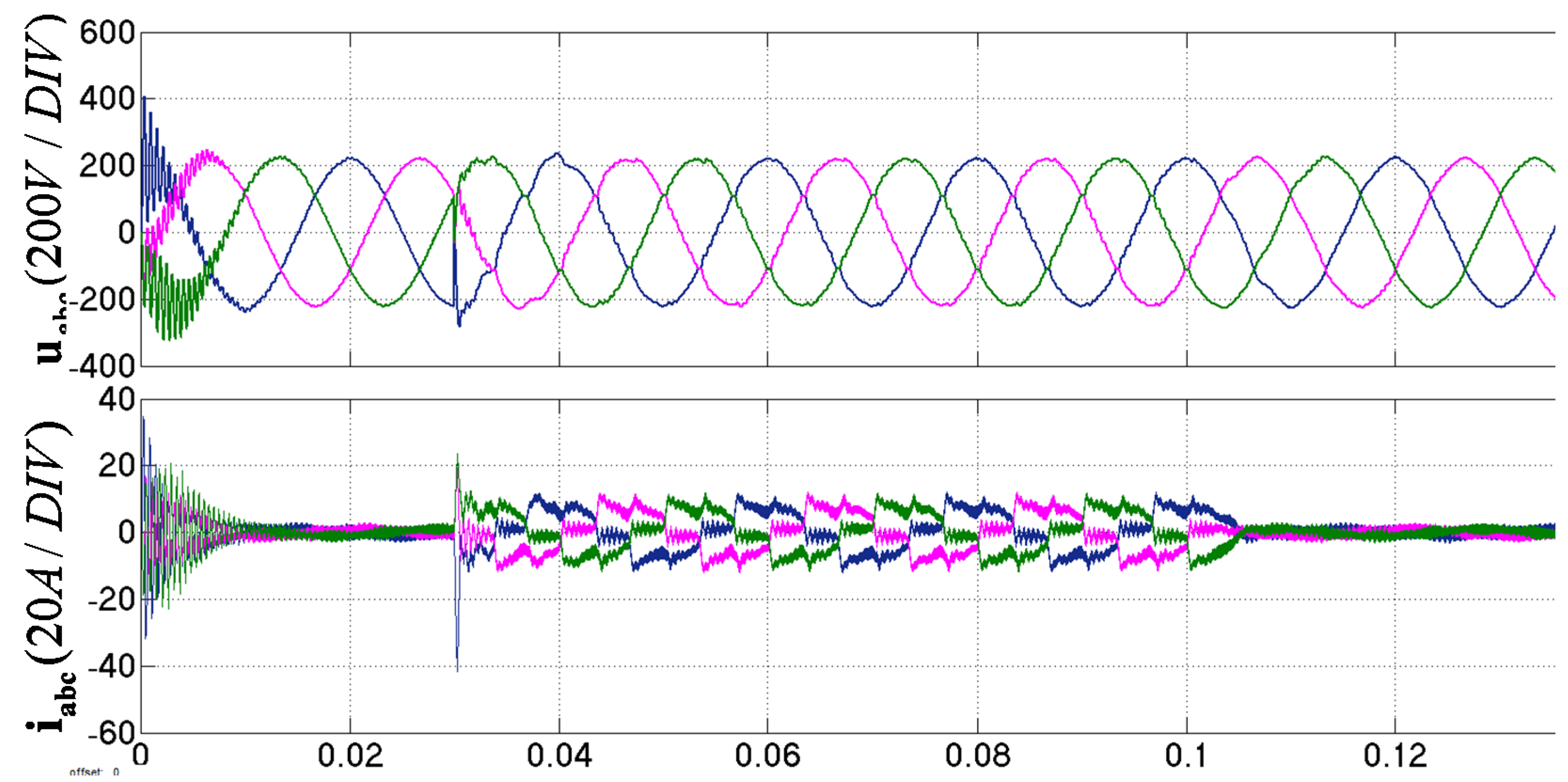
  • Scenario 1: The balanced resistive load is applied to the inverter output terminals at 0.03 s and then cut off at 0.1 s.
  • Scenario 2: The unbalanced resistive load is applied to the inverter output terminals at 0.03 s and then cut off at 0.1 s.
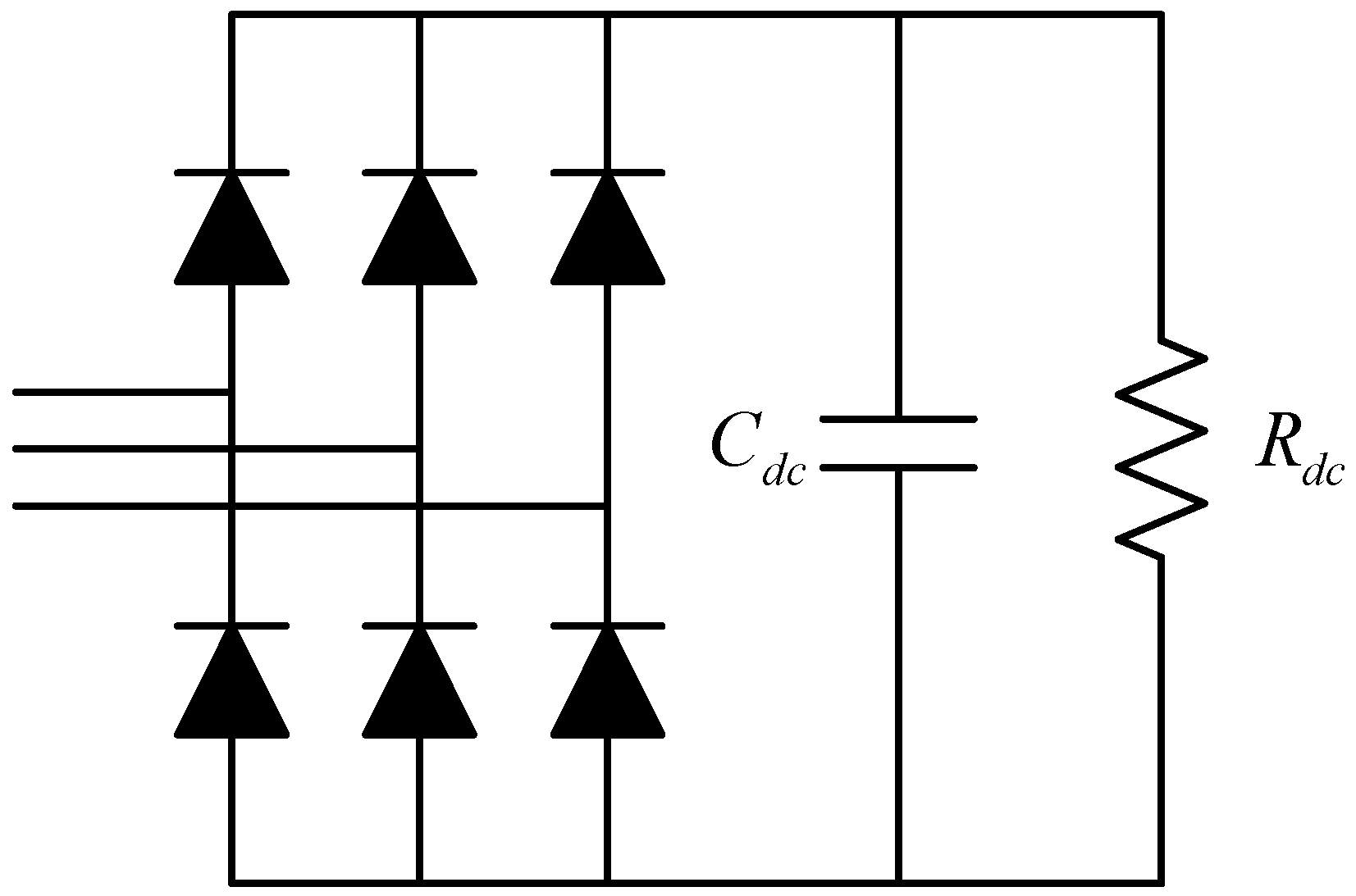
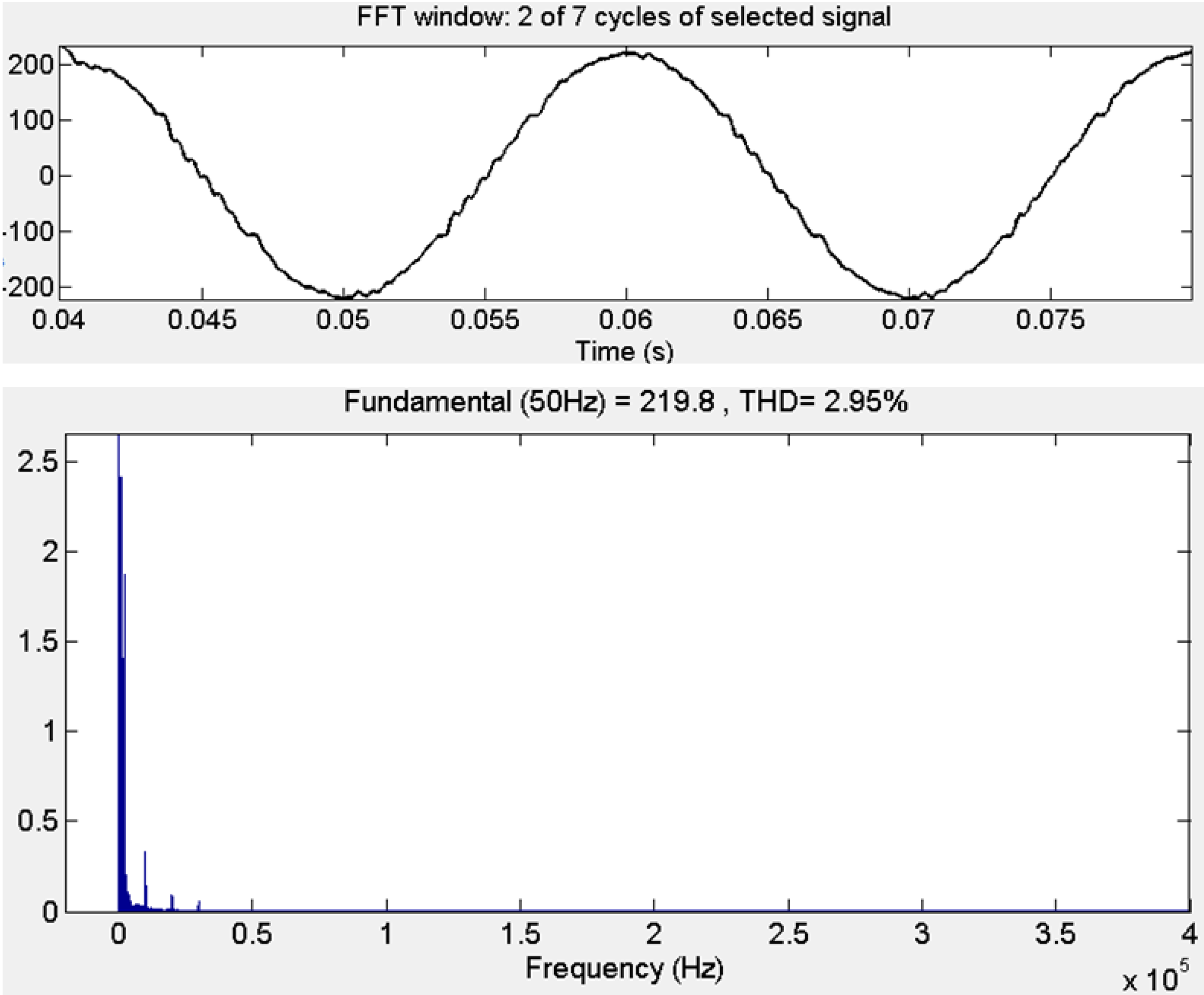
  • Scenario 3: The nonlinear resistive load is applied to the inverter output terminals at 0.03 s and then cut off at 0.1 s.
Figure 13, Figure 14 and Figure 15 show the simulation results of the proposed voltage controller using MATLAB/Simulink under the three different conditions mentioned above. Comparison simulation on the proposed control with and without LCO were conducted to verify its validity when the load changes.
Under the control of the proposed strategy without LCO, the output voltage had an instantaneous fluctuation of ±60 V in its amplitude when the balanced load was connected to or removed from the inverter output terminals as shown in Figure 13a. Furthermore, it took approximately 0.2 s for the output voltage to return to the steady-state status. While with the proposed LCO-based control strategy, the output voltage variation was mitigated significantly. As shown in Figure 13b, the output voltage variation reduces from 60 V to less than 10 V, which indicates that the proposed strategy with LCO obviously has a better performance in voltage control when the load current provided by the observer is introduced as the feedforward of the control strategy. Furthermore, the transient response of the output voltage waveforms is faster at the moment of the balanced load being instantaneously applied to the inverter output terminal. The advantage of LCO was also verified under Scenario 2, which is displayed in Figure 14a,b. As can be seen in Figure 15, the proposed voltage controller has a good performance under nonlinear load and the THD of the output voltage is kept at 2.95% as shown in Figure 17.
Figure 13. Simulation results of the propose control strategy under Scenario 1: (a) without LCO; (b) with LCO.
Energies 08 07542 g013aEnergies 08 07542 g013b
Figure 14. Simulation results of the propose control strategy under Scenario 2: (a) without LCO; (b) with LCO.
Energies 08 07542 g014aEnergies 08 07542 g014b
Figure 15. Simulation results of the propose control strategy with LCO under Scenario 3.
Energies 08 07542 g015
Figure 16. Nonlinear load circuit with a three phase diode rectifier.
Energies 08 07542 g016
Figure 17. Fast Fourier Transformation (FFT) analysis of output voltage under Scenario 3.
Energies 08 07542 g017
The parameters of the nonlinear load circuit are listed in Table 3.
Table 3. Parameters of the nonlinear load circuit.
ItemsValue
R d c 50 Ω
C d c 20 µF

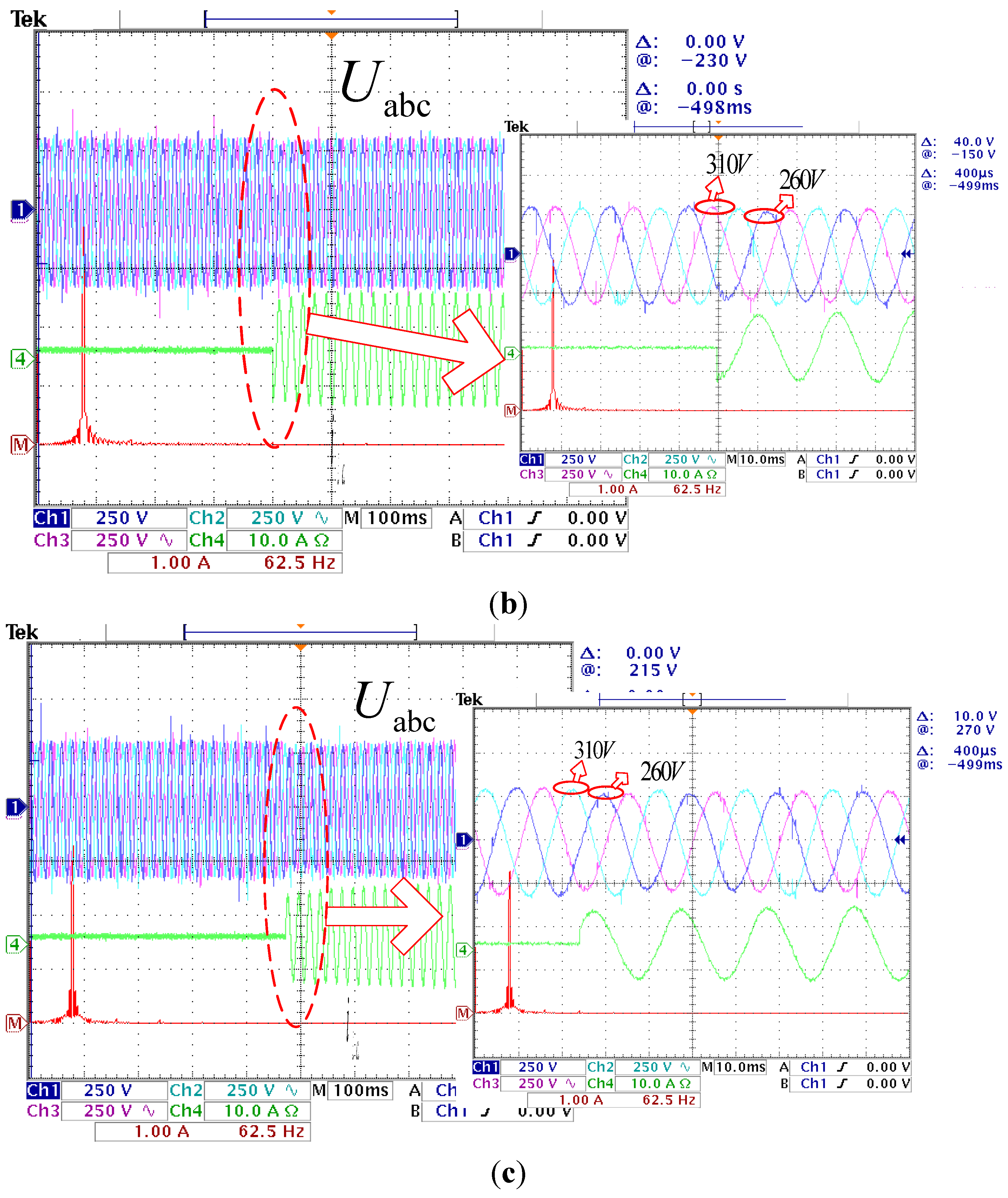
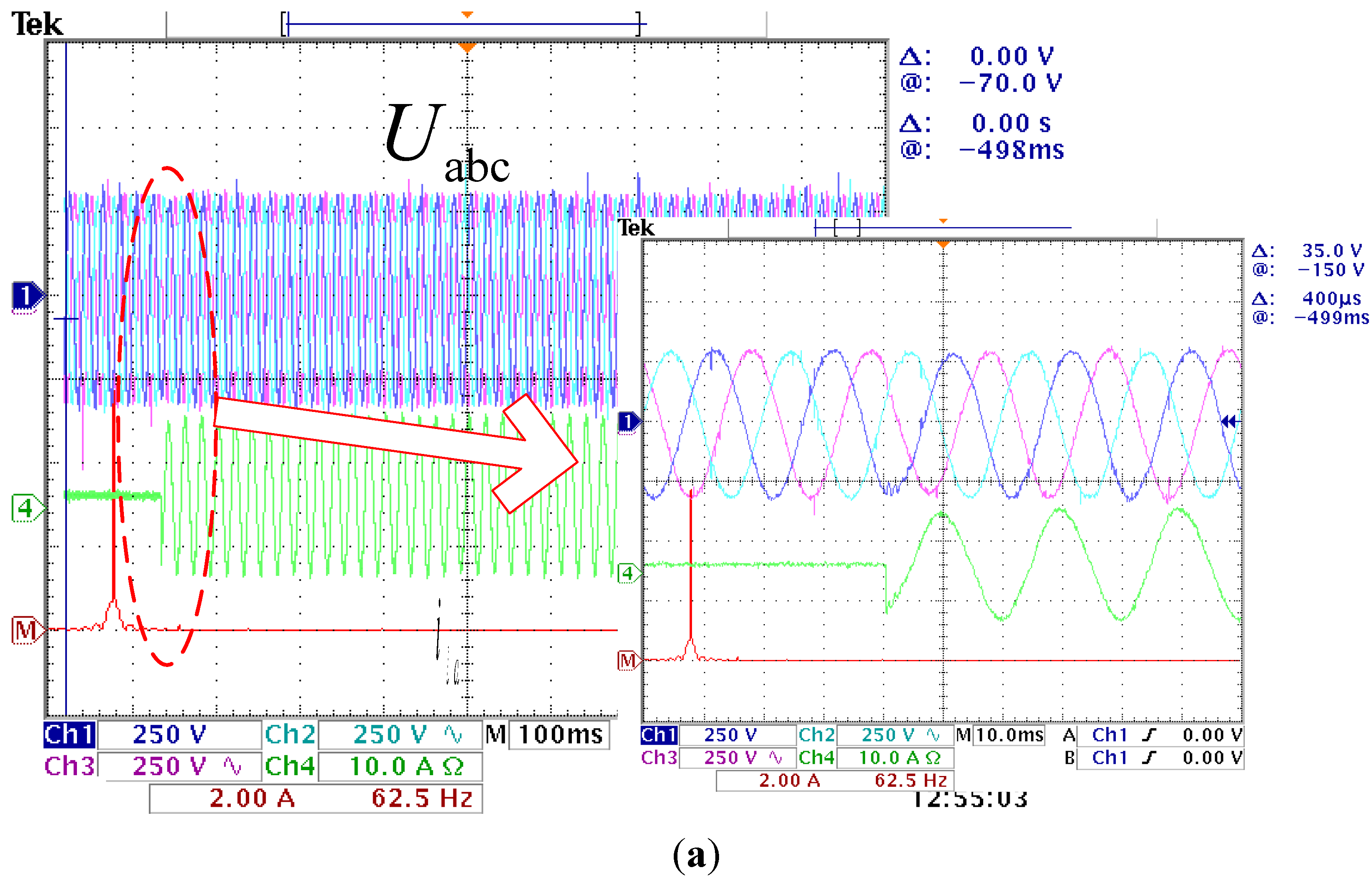
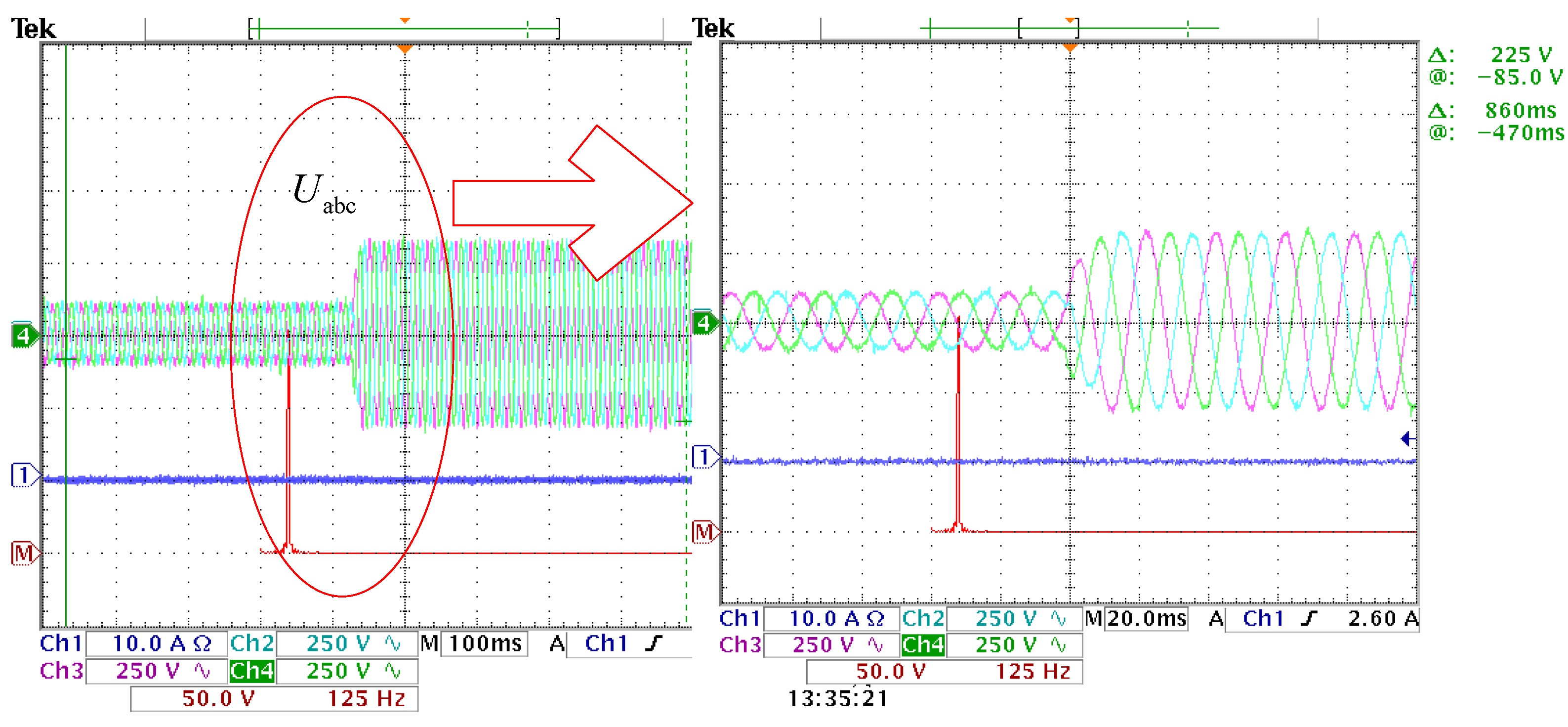
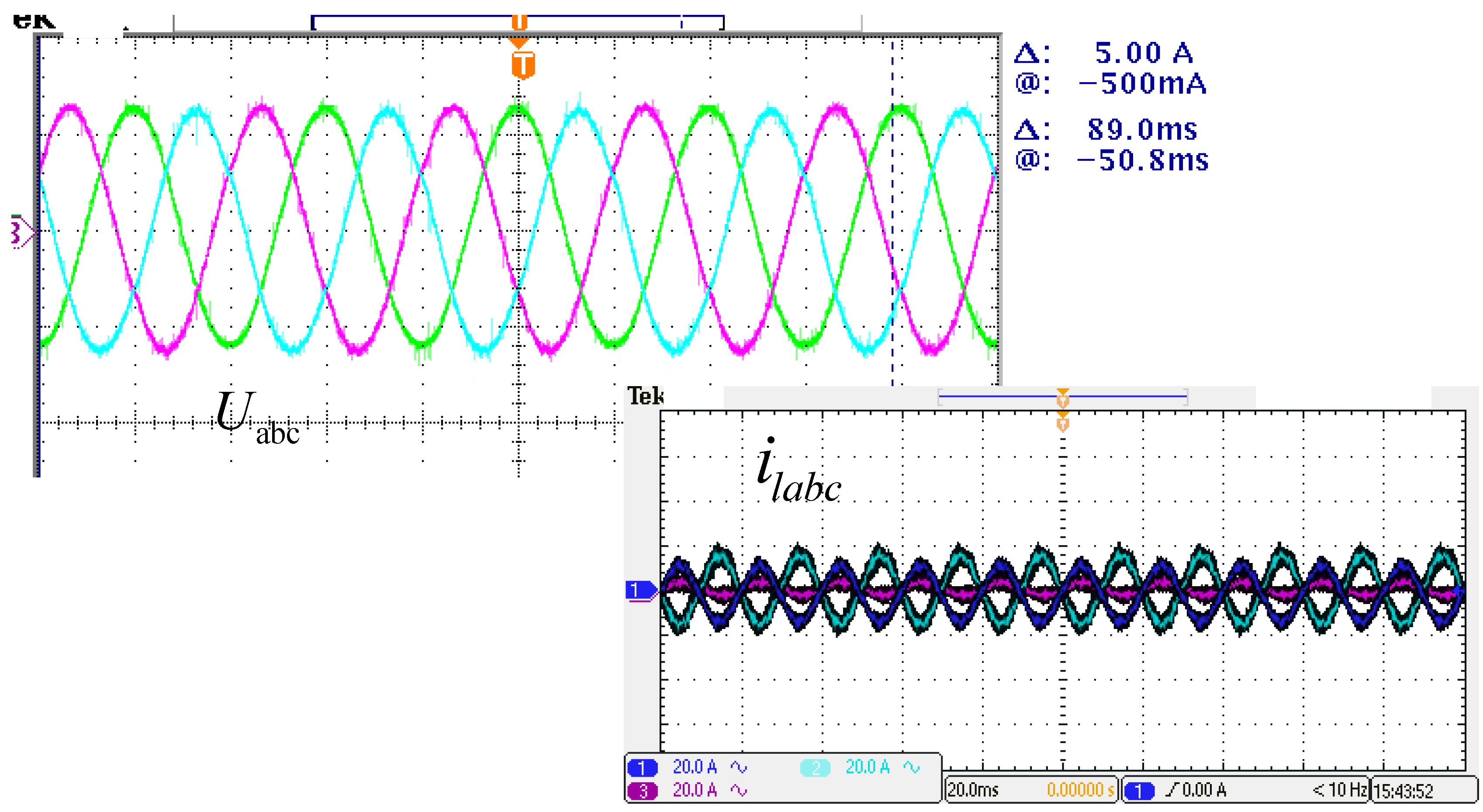
4.2. Experimental Test

To verify the effectiveness of the proposed LOC-based control strategy of three-phase inverter under a stationary frame, a three-phase prototype test system as illustrated in Figure 1 was built. The corresponding hardware experiment platform is shown in Figure 18, with its system parameters listed in Table 2.
In the experiments, comparisons of the traditional control and the proposed LOC-based control under balanced load, listed in the simulation part, were also conducted. The experimental results are listed in the following figures.
Figure 19a–c represent the experimental results of the proposed control scheme with and without LCO and traditional dual-loop control scheme when the balanced load is connected to the inverter terminals, respectively. As can be seen in the Figure 19a, the output voltage stays in the steady-state status without any decrease in its amplitude. While in Figure 19b–c, the output voltages both dropped from 311 V to 260 V with nearly 50 V of voltage disturbance at the moment of the load being connected. The experimental results are consistent with the simulation results above, which indicates the control strategy proposed in this paper shows an excellent performance on the dynamic response to the load disturbance. Figure 20 shows a stable state waveform of the system output voltage under unbalanced load, which proves that the proposed control strategy has also an excellent capacity of feeding unbalanced load. Figure 21 presents the waveform of the output voltage while the voltage reference rises to 311 V.
Figure 18. Hardware experiment platform.
Energies 08 07542 g018
Figure 19. Experimental results under balanced load switch. (a) Proposed control scheme with LCO; (b) Proposed control scheme without LCO; (c) Traditional dual-loop control scheme.
Energies 08 07542 g019aEnergies 08 07542 g019b
Figure 20. Experimental results of the proposed control strategy with LCO under unbalanced load.
Energies 08 07542 g020
Figure 21. Experimental results of the proposed control strategy with LCO when voltage reference rises to 311 V.
Energies 08 07542 g021

5. Conclusions and Future Work

This paper has proposed an optimal PR control strategy with LCO for a three-phase inverter of islanded microgrid. The effectiveness and feasibility of the proposed control strategy and its design method were proved by simulations and laboratory experiments.
(1)
The proposed control strategy is conducted in a stationary αβ frame, which has a feature of extensibility and suitability and is convenient for the implementation of multiple PR regulators with different center frequencies. Furthermore, it is easy and simple to design parameters of controllers for the reason that control signals under α-β coordinates need do not have to be decoupled.
(2)
The proposed control strategy applies load current as feedforward of dual-loop control, which makes a great contribution to its outstanding performance in voltage control such as zero steady-state error and low THD. Furthermore, the proposed control strategy has excellent dynamics including quick dynamic response and short regulation time, all of which ensure that the BESS has a strong ability to support unbalanced and nonlinear loads.
(3)
The proposed strategy can perfectly support renewable energy, which is beneficial for the spread and development of distributed generations.
Meanwhile, further work remains to be done to perfect the strategy. All of the models and analyses in this paper are based on a continuous domain, suitable for high switching frequency situations. The discrete-time model and corresponding controller design should be established and researched for low switching frequency situations.

Acknowledgments

This research was supported by the National High Technology Research and Development Program of China (Grant No. 2014AA052002), the National Natural Science Foundation of China (Grant No. 51307023 and 51177015), the Program for New Century Excellent Talents in University (Grant No. NCET-13-0129), the Natural Science Foundation of Jiangsu, China (Grant No. BK20130624), and the Technology Research Program of State Grid Corporation of China (SGCC, Grant No. 5211DS150015).

Author Contributions

Xiaobo Dou conceived and designed the proposed control strategy and model. Kang Yang significantly contributed to the implementation of the simulation and the writing of the paper. Xiangjun Quan and Yang Jiao contributed mainly to the laboratory test. Zaijun Wu, Qinran Hu, Bo Zhao and Peng Li were responsible for the guidance and a number of key suggestions. Shizhan Zhang contributed mainly to the analysis of the control parameters in this paper, which is of great significance for the proposed control strategy in this paper.

Conflicts of Interest

The authors declare no potential conflict of interest.

References

  1. Mehrizi-Sani, A.; Iravani, R. Potential-function based control of a microgrid in islanded and grid-connected modes. IEEE Trans. Power Syst. 2010, 25, 1883–1891. [Google Scholar] [CrossRef]
  2. Tan, X.; Li, Q.; Wang, H. Advances and trends of energy storage technology in Microgrid. Int. J. Electr. Power Energy Syst. 2013, 44, 179–191. [Google Scholar] [CrossRef]
  3. Serban, I.; Marinescu, C. Control strategy of three-phase battery energy storage systems for frequency support in microgrids and with uninterrupted supply of local loads. IEEE Trans. Power Electron. 2014, 29, 5010–5020. [Google Scholar] [CrossRef]
  4. Rocabert, J.; Luna, A.; Blaabjerg, F.; Rodríguez, P. Control of power converters in AC microgrids. IEEE Trans. Power Electron. 2012, 27, 4734–4749. [Google Scholar] [CrossRef]
  5. Kazmierkowski, M.P.; Malesani, L. Current control techniques for three-phase voltage-source PWM converters: A survey. IEEE Trans. Ind. Electron. 1998, 45, 691–670. [Google Scholar] [CrossRef]
  6. Karimi, H.; Davison, E.J.; Iravani, R. Multivariable servomechanism controller for autonomous operation of a distributed generation unit: Design and performance evaluation. IEEE Trans. Power Syst. 2010, 25, 853–865. [Google Scholar] [CrossRef]
  7. Jauch, T.; Kara, A.; Rahmani, M.; Westermann, D. Power quality ensured by dynamic voltage correction. ABB Rev. 1998, 4, 25–36. [Google Scholar]
  8. Perera, A.A.D.R. Development of Controllers for the Dynamic Voltage Restorer. Master’s Thesis, Nanyang Technological University, Singapore, 2000. [Google Scholar]
  9. Vilathgamuwa, M.; Perera, A.A.D.R.; Choi, S.S. Performance improvement of the dynamic voltage restorer with closed-loop load voltage and current-mode control. IEEE Trans. Power Electron. 2002, 17, 824–834. [Google Scholar] [CrossRef]
  10. Loh, P.C.; Newman, M.J.; Zmood, D.N.; Holmes, D.G. A comparative analysis of multiloop voltage regulation strategies for single and three-phase UPS systems. IEEE Trans. Power Electron. 2003, 18, 1176–1185. [Google Scholar]
  11. Vilathgamuwa, D.M.; Wijekoon, H.M. Control and analysis of a new dynamic voltage restorer circuit topology for mitigating long duration voltage sags. In Proceedings of the 37th Industry Applications Conference (IAS), Pittsburgh, PA, USA, 13–18 October 2002; IEEE: New York, NY, USA, 2002; Volume 2, pp. 1105–1112. [Google Scholar]
  12. Makki, A.; Bose, S.; Giuliante, T.; Walsh, J. Using hall-effect sensors to add digital recording capability to electromechanical relays. In Proceedings of the 63rd Protective Relay Engineers, College Station, TX, USA, 29 March–1 April 2010; IEEE: New York, NY, USA, 2010; pp. 1–12. [Google Scholar]
  13. Pankau, J.; Leggate, D.; Schlegel, D.; Kerkman, R.; Skibiniski, G. High frequency modeling of current sensors. In Proceedings of the 14th Applied Power Electronics Conference and Exposition (APEC’99), Dallas, TX, USA, 1999; IEEE: New York, NY, USA, 1999; Volume 2, pp. 788–794. [Google Scholar]
  14. Hornik, T.; Zhong, Q.C. Control of grid-connected DC-AC converters in distributed generation: Experimental comparison of different schemes. In Proceedings of the Compatibility and Power Electronics (CPE’09), Badajoz, Spain, 5–22 May 2009; IEEE: New York, NY, USA, 2009; pp. 271–278. [Google Scholar]
  15. Yang, S.; Lei, Q.; Peng, F.Z.; Qian, Z. A robust control scheme for grid-connected voltage-source inverters. IEEE Trans. Ind. Electron. 2011, 58, 202–212. [Google Scholar] [CrossRef]
  16. Teodorescu, R.; Blaabjerg, F.; Liserre, M.; Loh, P.C. Proportional-resonant controllers and filters for grid-connected voltage-source converters. IEE Proc.-Electr. Power Appl. 2006, 153, 750–762. [Google Scholar] [CrossRef]
  17. Ahmed, K.H.; Massoud, A.M.; Finney, S.J.; Williams, B.W. A modified stationary reference frame-based predictive current control with zero steady-state error for LCL coupled inverter-based distributed generation systems. IEEE Trans. Ind. Electron. 2011, 58, 1359–1370. [Google Scholar] [CrossRef]
  18. Zeng, G.; Rasmussen, T.W. Design of current-controller with PR-regulator for LCL-filter based grid-connected converter. In Proceedings of the 2nd IEEE International Symposium on Power Electronics for Distributed Generation Systems (PEDG), Hefei, China, 16–18 June 2010; IEEE: New York, NY, USA, 2010; pp. 490–494. [Google Scholar]
  19. Shen, G.; Zhu, X.; Zhang, J.; Xu, D. A new feedback method for PR current control of LCL-filter-based grid-connected inverter. IEEE Trans. Ind. Electron. 2010, 57, 2033–2041. [Google Scholar] [CrossRef]
  20. Marconi, L.; Teel, A.R. Internal model principle for linear systems with periodic state jumps. IEEE Trans. Autom. Control 2013, 58, 2788–2802. [Google Scholar] [CrossRef]
  21. Wu, Y.; Shang, R.; Guo, X.; Li, Y.; Yu, H. The comparative analysis of PI controller with PR controller for the single-phase 4-quadrant rectifier. In Proceedings of the IEEE Transportation Electrification Conference and Expo Asia-Pacific (ITEC Asia-Pacific), Beijing, China, 31 August–3 September 2014; IEEE: New York, NY, USA, 2014; pp. 1–5. [Google Scholar]

