
Development of Optical Fiber-Based Daylighting System and Its Comparison

1
Graduate Institute of Color and Illumination Technology, National Taiwan University of Science and Technology, #43, Section 4, Keelung Road, Taipei 106, Taiwan
2
Graduate Institute of Electro-Optical Engineering, National Taiwan University of Science and Technology, #43, Section 4, Keelung Road, Taipei 106, Taiwan
3
Department of Electronic and Computer Engineering, National Taiwan University of Science and Technology, #43, Section 4, Keelung Road, Taipei 106, Taiwan
*
Author to whom correspondence should be addressed.
Energies 2015, 8(7), 7185-7201; https://doi.org/10.3390/en8077185
Submission received: 7 June 2015
/
Revised: 6 July 2015
/
Accepted: 7 July 2015
/
Published: 15 July 2015
Abstract
:Fiber-optic daylighting systems have been shown to be a promising and effective way to transmit sunlight in the interior space whilst reducing electric lighting energy consumption. To increase efficiency in terms of providing uniform illumination in the interior, the current need is to illuminate optical fiber-bundle with uniform light flux. To this end, we propose a method for achieving collimated light, which illuminates the fiber-bundle uniformly. Light is collected through a parabolic concentrator and focused toward a collimating lens, which distributes the light over each optical fiber. An optics diffusing structure is utilized at the end side of the fiber bundle to spread light in the interior. The results clearly reveal that the efficiency in terms of uniform illumination, which also reduces the heat problem for optical fibers, is improved. Furthermore, a comparison study is conducted between current and previous approaches. As a result, the proposed daylighting system turns out convenient in terms of energy saving and reduction in greenhouse gas emissions.
1. Introduction
People living in urban areas spend most of their daylight hours under artificial light. In the absence of daylight, individuals are susceptible to detrimental effects [1]. Moreover, conventional candescent and fluorescent lamps have been indicated in aggravating depression, aggression, eye strain, reduced muscle strength, obesity, and diabetes [1]. As the degree of human satisfaction in the interior depends on various factors (visual design and psychological factors), daylight plays an important role in improving health.
A reduction in energy consumption and the production of energy through renewable energy sources can lead to a lower production of greenhouse gas emissions, which is becoming an increasingly serious global issue [2]. Daylighting has a significant role in the field of renewable energy in terms of reducing the use of electricity, which has been significantly increasing in many countries [2]. It is estimated that buildings are one of the main sources of power consumption and greenhouse gas emissions where most of the energy is utilized to create a thermally and visually comfortable built environment. Energy consumption in residential and commercial buildings is nearly 40.40% of the total energy consumed [3], and electricity demand is growing by 0.7% per year in buildings in the USA [2]. In Europe, about 40% of the total electricity is used for indoor lighting in buildings [4]. As a result, more attention has been paid to energy consumption in buildings where lighting is the major source of energy utilization. It has been estimated that energy consumption due to electric lighting in buildings is approximately 40%–50% of the total energy cost [5] where one of the reasons is the growth of lighting demand because of raised average illuminance levels in buildings, especially in newly constructed buildings. To solve energy issues, sustainable buildings are introduced. One of the principles of these buildings is to illuminate the building by daylight instead of artificial light at all times of the day to reduce the overall energy consumption. Buildings in which efficient daylighting methods are applied can reduce electric lighting energy consumption by 50%–80% [6].
In sustainable development, the interior of buildings is illuminated by daylight through the openings, the windows, and the daylighting system. Light through windows decreases very rapidly, and interior areas may not have sun exposure. As a result, the illumination is not consistent and some areas may remain dark, which produces visual discomfort due to non-uniform illumination in the interior space. According to European Standard, the requirement for the office buildings is to achieve an average illuminance of 500 lx [7]. However, it is difficult to achieve 500 lx at all times of the day through only windows and openings. To this end, a daylighting scheme is required to illuminate the interior space during the day.
Several concepts regarding daylighting systems have been demonstrated using light pipes [8,9,10,11,12] and optical fibers [13,14,15,16,17,18,19,20,21,22,23,24,25,26,27]. Most of the designs have issues of non-uniformity and low efficiency in terms of illuminance. In the previous study, we analyzed losses and improved two fiber-optic daylighting systems using a parabolic reflector and Fresnel lens through simulation and real experiments [13]. During the development, the efficiency of the system was improved via uniform illumination over the fiber bundle and by reducing the heat problem, which had critical importance for the plastic optical fiber (POF).
There has been a trend toward reducing the electric lighting power consumption via new technologies. The possible ways to do this include the use of light controls, light sources with high luminous efficacy, and daylighting. Furthermore, high-performance light-emitting diodes (LEDs), compact fluorescent lamps, and incandescent lamps are used to replace low-efficacy light sources. In this study, LED light sources are used to maintain the required illumination level when daylight is not available. It has been investigated that a hybrid lighting system gives better illumination quality [13]. This research also improves the efficiency of the hybrid lighting system.
The objective of this study is to achieve uniform light into the optical fibers and deliver it in the interior space. Consequently, we propose a novel approach for the parabolic reflector. Sunlight is concentrated and focused toward a collimating lens, and then collimated light is transmitted into the optical fibers. As a result, uniform light is achieved in each optical fiber.
We present a simulation study of the proposed daylighting system. LightTools®, which is a well-known optical-simulation tool [9,13,14,23], is used to design the optical and mechanical components of the daylighting system and estimate the illuminance levels in the interior space. SolidWorksTM is used to design some mechanical parts. DIALuxTM, which is widely used for indoor and outdoor lighting simulation [23,28], is used to show the interior space under lighting simulation.
The remainder of the paper is organized in the following manner. Section 2 describes background where different issues of previous systems are described. The design of proposed daylighting system is discussed in Section 3. In Section 4, light-transmission media and the light distribution in the interior are detailed. In Section 5, we describe the complete study, involving the simulation and the evaluation of the results in three stages. Stage one investigated the illuminance levels on the fiber bundle. Stage two includes illuminance levels in the interior where comparison with other designs is detailed. Stage three describes energy-saving of the hybrid approach. Finally, brief concluding remarks and future work are included in Section 6.
2. Background
To date, most studies have been dedicated to active daylighting schemes that include sun-tracking device. Because active daylighting systems have high efficiency than that of passive daylighting systems, they are preferred to install in buildings. Most of them have issue of non-uniformity, which is a critical problem in lighting systems. To achieve uniform illumination, fiber-bundle should be illuminated uniformly. In this section, we will discuss non-uniformity issue in previous fiber-based daylighting schemes [24,25,26,27]. Ray-tracing simulation is performed to show non-uniformity over fiber bundle for each approach. It is noted that we used our own measurements for illustrating non-uniformity in previous methods.
The idea of capturing high-intensity sunlight was researched in which a parabolic reflector concentrated sunlight into a single optical fiber through a flat mirror [24], as shown in Figure 1a. They used fused-silica optical fibers for light transmission, and diameter of the fiber was 1 mm. The parabolic dish had a diameter of 0.2 m. After reflection of light at the parabolic surface, most of the light was lost through it by hitting the outer surface of the optical fiber. As a result, most of the light was not able to reach the flat reflector. They used small parabolic dishes to collect sunlight. However, the large number of parabolic dishes occupied a large area. Each parabolic dish needed a separate sun-tracking module, which increased the cost of the system. The system was used for solar thermal applications to produce energy rather than daylighting. For daylighting, a system should contain a minimum number of concentrators. Therefore, this approach is not suitable for installing the concentrators on the roofs of buildings. If they used fiber-bundle instead of a single fiber, uniform illumination was not attained, even with a very high concentration of light.
Figure 1.
Physical layout of the daylighting system for the (a) parabolic and flat reflectors; (b) parabolic and hyperbola reflectors; (c) offset parabolic reflector; and (d) Fresnel lens.
Figure 1.
Physical layout of the daylighting system for the (a) parabolic and flat reflectors; (b) parabolic and hyperbola reflectors; (c) offset parabolic reflector; and (d) Fresnel lens.
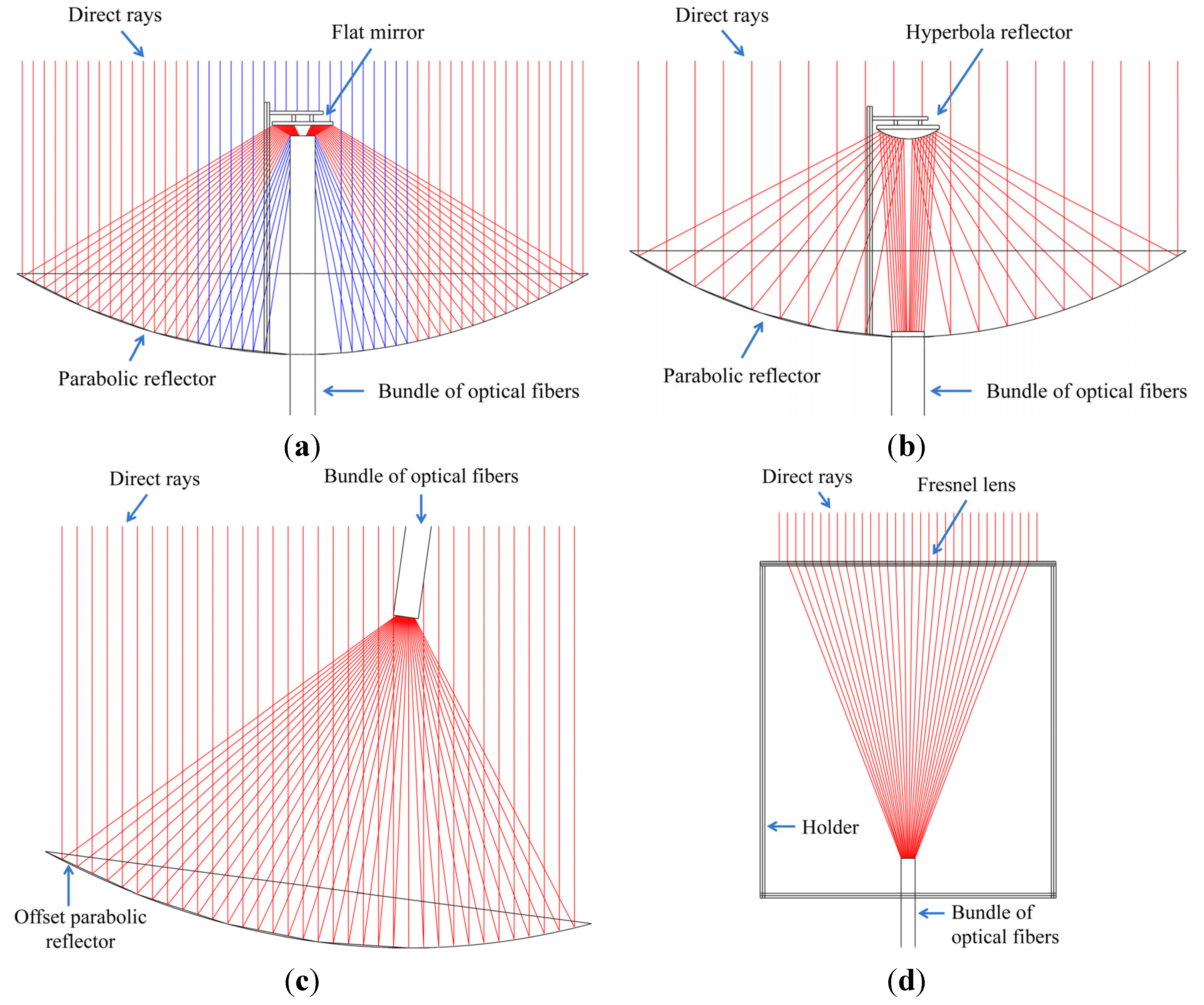
In [25], they used parabolic and hyperbola reflectors to capture sunlight. The light was concentrated through a parabolic reflector and then light was reflected toward the hyperbola reflector. Finally, the light was inserted into optical fibers to transmit it into the interior. In this approach, we found two problems: the heat and non-uniformity. The central optical fibers in the bundle were over shadowed due to the blockage of direct sunlight from the hyperbola reflector, and some optical fibers had high intensity of light, as shown in Figure 1b. Overall, the fiber-bundle was illuminated non-uniformly.
A parabolic dish-based approach was presented in [26]. They concentrated light through an offset parabolic reflector, and then light was focused over the fiber-bundle, as shown in Figure 1c. The optical fibers in the bundle were not well arranged. Since they didn’t use symmetric parabolic reflector, the illumination into each fiber was not uniform. In addition, they did not highlight illuminance on the fiber bundle. Thus, we designed this system and performed simulation to show non-uniformity over fiber bundle.
In the Himawari solar lighting system, Fresnel lens was used to collect sunlight, and only visible light was inserted into optical fibers [27], as shown in Figure 1d. It had two series of models with a different number of lenses and fibers in the bundle. All models contained quartz-glass optical fibers (QOFs) that exhibited low losses during light transmission. However, the system was costly due to the price of QOFs. The system combined six optical fibers in each bundle for light distribution, and the illumination angle from the fiber bundle was 58 degrees. The luminous flux per cable was 1920 lm. Overall, the light capturing and distribution method was not well defined in terms of it achieving uniform illumination.
We demonstrated a system using parabolic reflectors in [13]. Light was concentrated through concave parabolic reflector and reflected toward fiber bundle though convex parabolic reflector. Both reflectors were designed and arranged to produce collimated uniform light for optical fibers. In this approach, we found two problems: shadow, which decreased illuminance, on the fiber bundle and difficult to manufacture and align convex parabolic reflector. To solve these issues, we propose a system using concave parabolic reflector and plano-concave lens in this study.
3. Proposed Daylighting System
In concentrated solar energy applications, the parabolic reflector has gained popularity due to them being widely available for rapid manufacturing. They are “point-focus” concentrators that can achieve very high concentration ratios, sometimes even above 1000 suns. They are used to achieve a high concentration of sunlight in solar concentration systems.
The idea behind the system is to capture sunlight and then focus it over the bundle of optical fibers. As parabolic reflector focused sunlight onto a small area, it didn’t insert maximum light into optical fibers. The light needed to be achieved over the fiber bundle with uniform light flux. Each fiber should have the same intensity of light for the uniform distribution of light. To this end, we proposed a design in which collimated light is produced to solve the above issue. We mounted collimating lens upstream of the focal point of the parabolic reflector to produce uniform illumination.
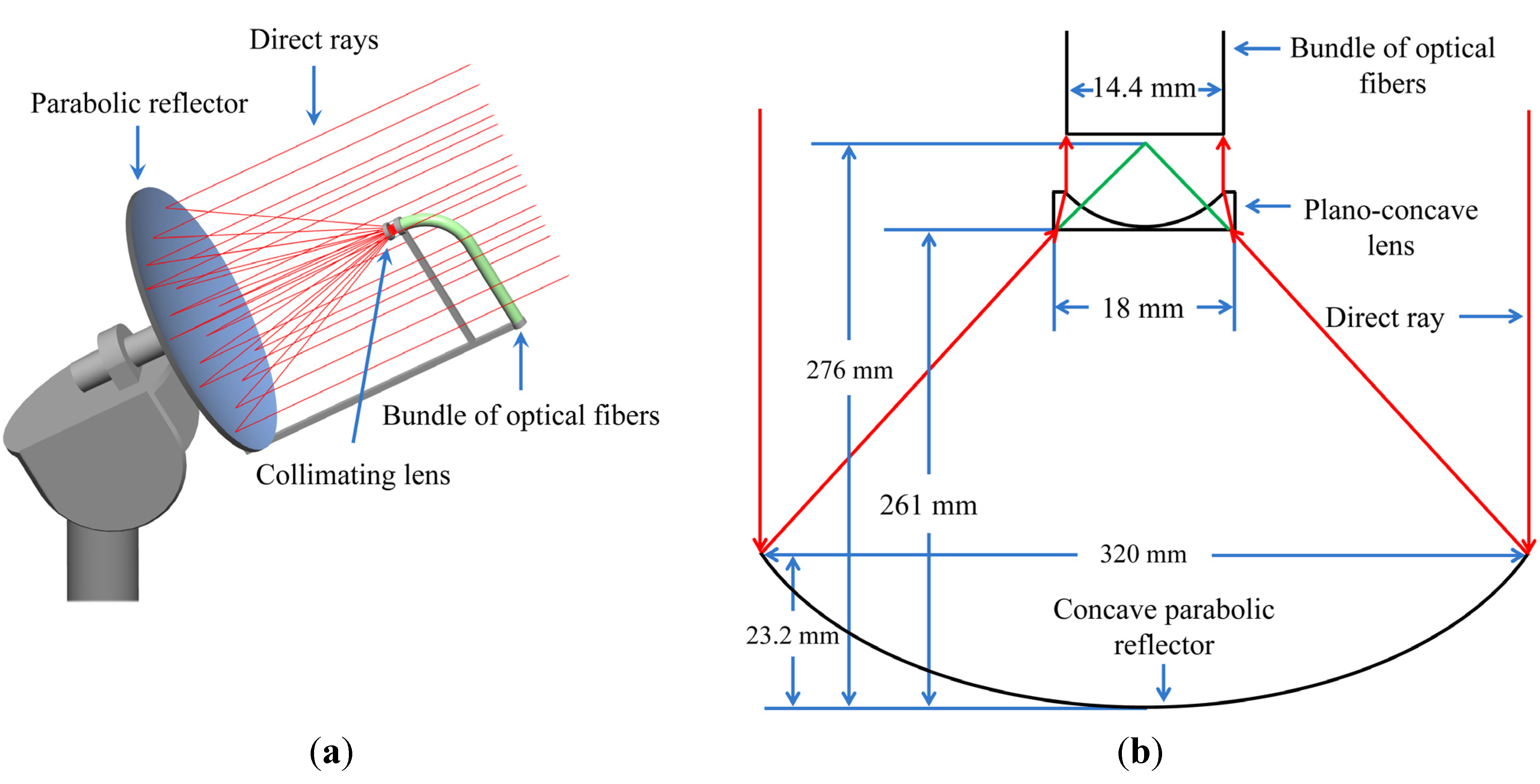
The sunlight collecting unit using the parabolic reflector and collimating lens is shown in Figure 2. Direct sunlight hit the surface of the reflector and reflected toward a collimating lens to produce uniform light. After being collimated, the light was entered into optical fibers. Uniform illumination was accomplished through the collimating lens by:
where Dp is the diameter of the concave region of the plano-concave lens and Dr is the diameter of the receiver (bundle of optical fibers). Both Dr and Dp should be same (14.4 mm) to insert maximum light into optical fibers. If Dp is increased, most of the light will not enter into the optical fibers. Conversely, we shall get non-uniform light and produce heat problem if Dp is decreased. Likewise, we shall lose light by increasing or decreasing the Dr. However, we can modify Dp and Dr, if we change parameters (e.g., focal length and diameter) of the light collector (parabolic reflector) accordingly. The focal length of the collimating lens was calculated by [29]:
where NA is the numerical aperture of the concentrator and D is the diameter of the collimating lens. Measurements of reflectors, lenses, and other parameters are shown in Table 1.
Figure 2.
(a) Scheme of the proposed daylighting system; (b) Schematic diagram of the design to produce collimated illumination.
Figure 2.
(a) Scheme of the proposed daylighting system; (b) Schematic diagram of the design to produce collimated illumination.


| Parameters of diffuser lens | Value (mm) |
|---|---|
| Radius of biconcave lens | 12 |
| Focal length of biconcave lens | 13.2 |
| Focal length of concavo convex lens | 11.3 |
| Radius-1 of concavo convex lens | 12 |
| Radius-2 of concavo convex lens | 3.6 |
4. Daylight Transmission and Distribution
We used silica optical fibers to reduce heat problem, and POFs were used for most of the transmission part due to their low cost, flexibility, strength, and acceptability for complex wiring in buildings. Silica optical fibers (SOFs) and POFs have a core diameter of 1.457 and 1.98 mm and a cladding diameter of 1.8 mm and 2 mm, respectively.
Most of the optical fiber-based daylighting systems had heat problem, which was solved for the parabolic reflector by varying the size of the concentrator and optical fibers in the bundle [13]. As a result, we obtained the best match of the fiber bundle for the concentrator. In the present study, we used same size of the concentrator for the fiber bundle as that of previous system mentioned in [13] to reduce the heat problem.
To install optical fiber in the building, bending limits should be considered to reduce losses for light transmission [30]. In [20], optical fiber with diameter of 3 mm had a critical bending radius of 56 mm. Likewise, light pipe bend may reduce light efficiency by approximately 8% [31].
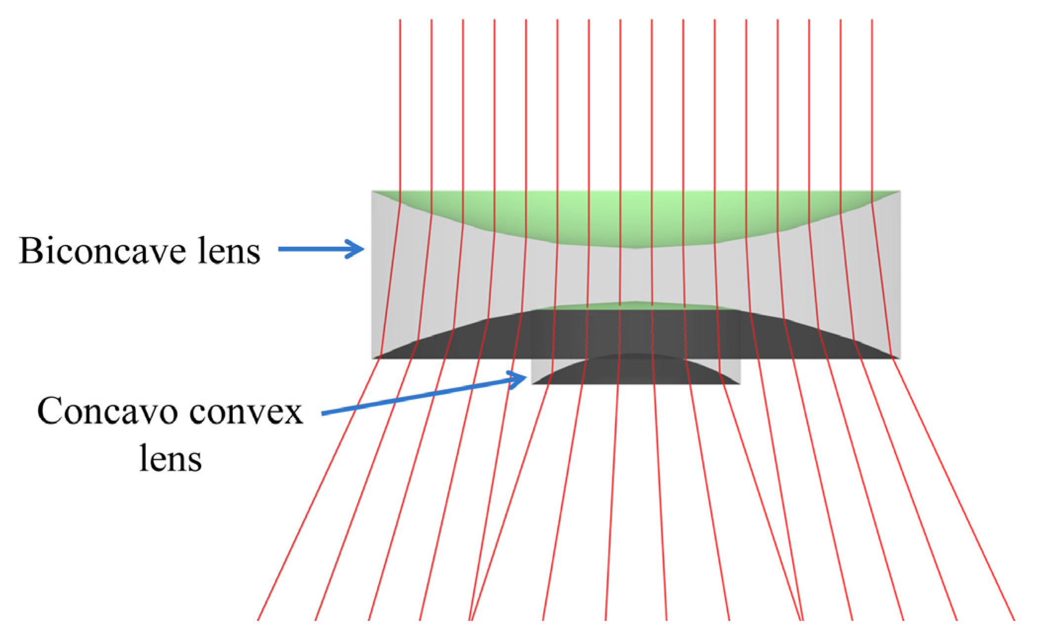
Recently, numerous approaches have been presented to achieve uniform illumination from light sources [32,33]. In solid-state lighting, this issue has gained critical importance. Similarly, uniform illumination is mandatory in daylighting. To spread the light from the optical fibers, which had a high beam of light, they were divided into different bundles, and optical fibers in each bundle were organized into a circular shape. Each fiber bundle covered a surface area of 78.54 mm2. A diverging lens was the best choice for the light distribution, as shown in Figure 3. The focal length of the thin lens can be determined by the lens maker’s formula, which can be written as [34]:
where r1 and r2 are the two radii and n is the refractive index of the material. The lenses had a refractive index of 1.459. Measurements of distributing lenses are mentioned in Table 1. It is noted that we used a biconcave lens at the end side of the fiber bundle to diverge light in the previous approach [13]. In [23], we used a combination of a biconcave lens and a concavo convex lens to spread light in the interior. Because combination of two lenses gave good performance than a single lens, we preferred to use a combination of lenses for the light distribution in the interior space. As a result, we have improved illuminance uniformity in the interior.
Figure 3.
Behavior of the incident light on the diffuser lens.

5. Simulation and Results
We simulated the proposed design using optical software (LightTools®) to evaluate that the daylighting system can offer required illumination. For daylight, lumens was calculated to simulate the entire optical design for indoor by [35]:
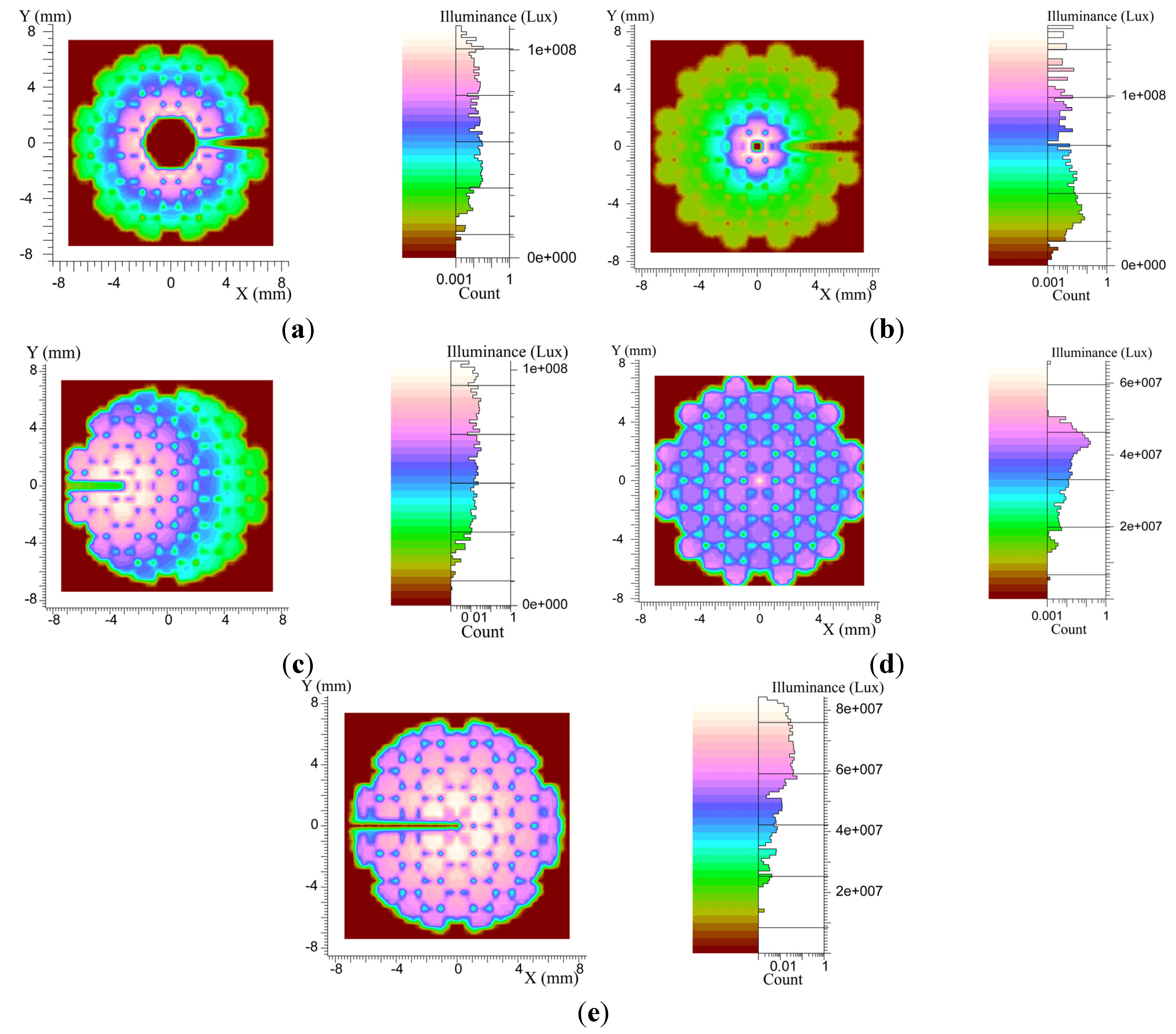
where E' is the measured illuminance, dF is the input luminous flux in lumens, and dS is the area of the concentrator. We calculated the simulated input flux from the measured illuminance by using Equatiom (4). The measured illuminance at different times of the day outdoors and at the calculated flux are mentioned in Table 2. To check illuminance uniformity on the fibers’ ends, 500 K rays were used. In Figure 4, we show simulation results that were achieved from different designs. Each system was designed, and simulation was performed to show the results. As shown in Figure 4a, low illuminance was achieved in the center of the fiber bundle [24]. Therefore, illuminance was not uniform on the fiber bundle. In Figure 4b, high illuminance was attained in the center of the fiber bundle because more light was focused in the center [25], and other fibers had low illuminance. Therefore, this design was not suitable for optical fiber-based daylighting. An offset parabolic reflector gave high illuminance on one side of the fiber bundle [26], as shown in Figure 4c. In Figure 4d, the illuminance is uniform [27], but it is less than the current approach. In our previous approach [13], illuminance over fiber bundle was uniform, but it had less illuminance and more shadow on fiber bundle than the current approach. However, the results in [13] were better than previous approaches [24,25,26,27]. As evident from Figure 4e, uniform illumination was achieved over the fiber bundle using the proposed approach, and each optical fiber had similar illuminance. We have reduced shadow on the fiber bundle and increased illuminance value, as compared to our previous approach for the parabolic reflector [14].
Figure 4.
Uniform illumination on the surface of optical fibers’ ends for the (a) parabolic and flat reflectors; (b) parabolic and hyperbola reflectors; (c) offset parabolic reflector; (d) Fresnel lens and (e) proposed approach.
Figure 4.
Uniform illumination on the surface of optical fibers’ ends for the (a) parabolic and flat reflectors; (b) parabolic and hyperbola reflectors; (c) offset parabolic reflector; (d) Fresnel lens and (e) proposed approach.

Table 2.
Average illuminance at different times of the day and the calculated flux for the concentrator.
| Time | Solar Altitude (°) | Outdoor Illuminance (lx) | Input Flux (lm) |
|---|---|---|---|
| 12:00 | 74 | 110,000 | 11,255 |
| 13:00 | 65 | 105,000 | 10,745 |
| 14:00 | 54 | 100,000 | 10,240 |
| 15:00 | 43 | 80,000 | 8,186 |
| 16:00 | 31 | 60,000 | 6,140 |
| 17:00 | 19 | 40,000 | 4,093 |
| 18:00 | 8 | 20,000 | 2,047 |
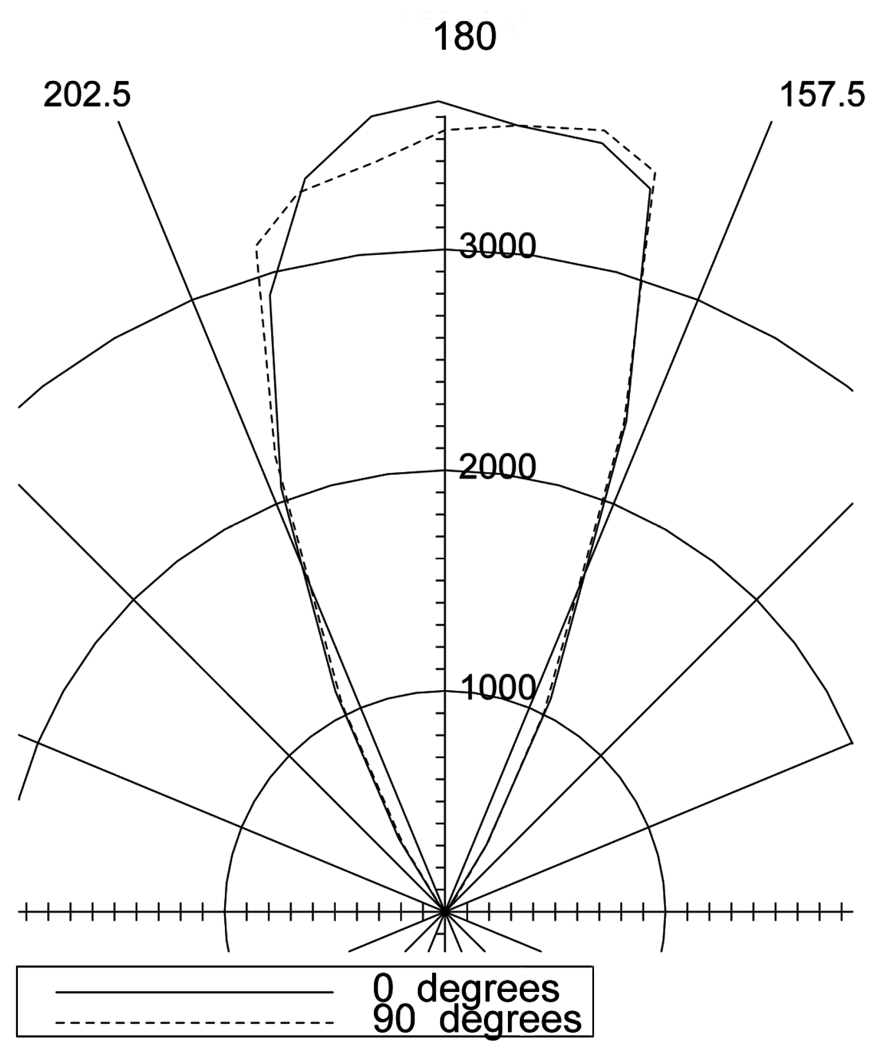
We mounted two daylighting systems using current design to the test office. Since fiber bundle in each system had 55 optical fibers, fibers were arranged into six bundles, and then placed at different positions to illuminate the interior. Our main goal was to illuminate a large area with an average illuminance of more than 500 lx. To use small lenses for the distribution of light, optical fibers in each bundle were organized to form a circular shape. The candle power distribution curve of the fiber bundle, which had nineteen optical fibers, is shown in Figure 5.
Figure 5.
The candle-power distribution curve of the fiber bundle.

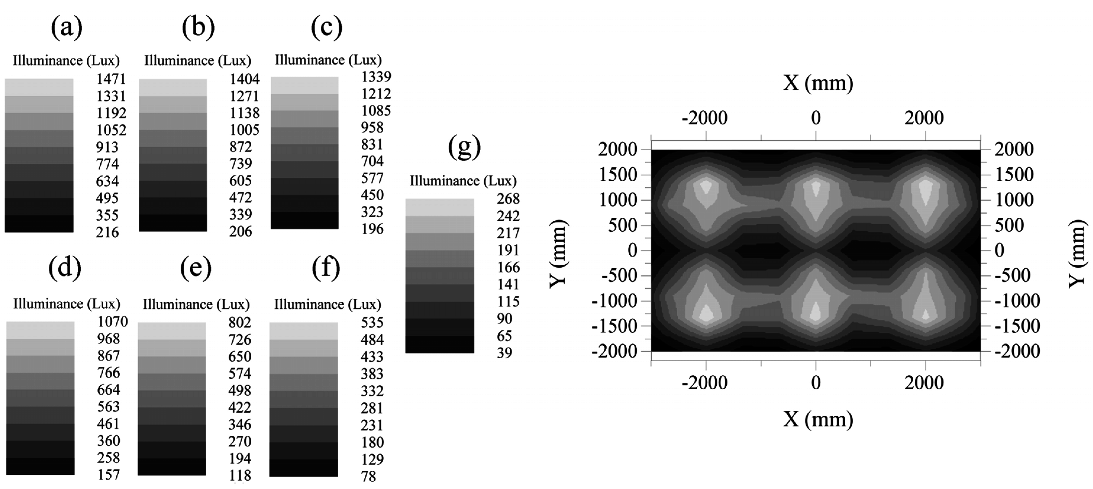
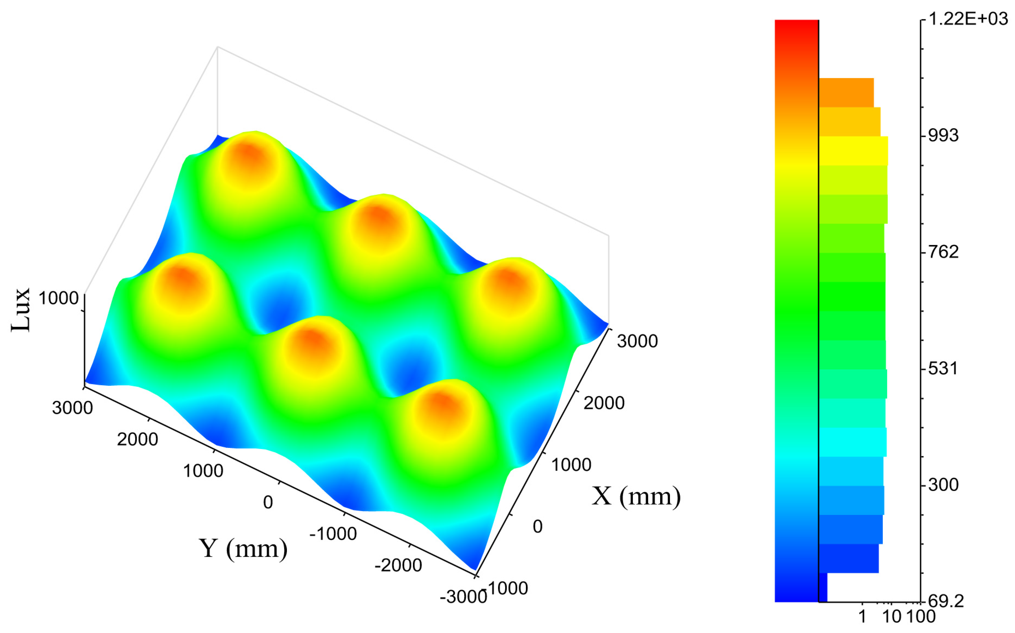
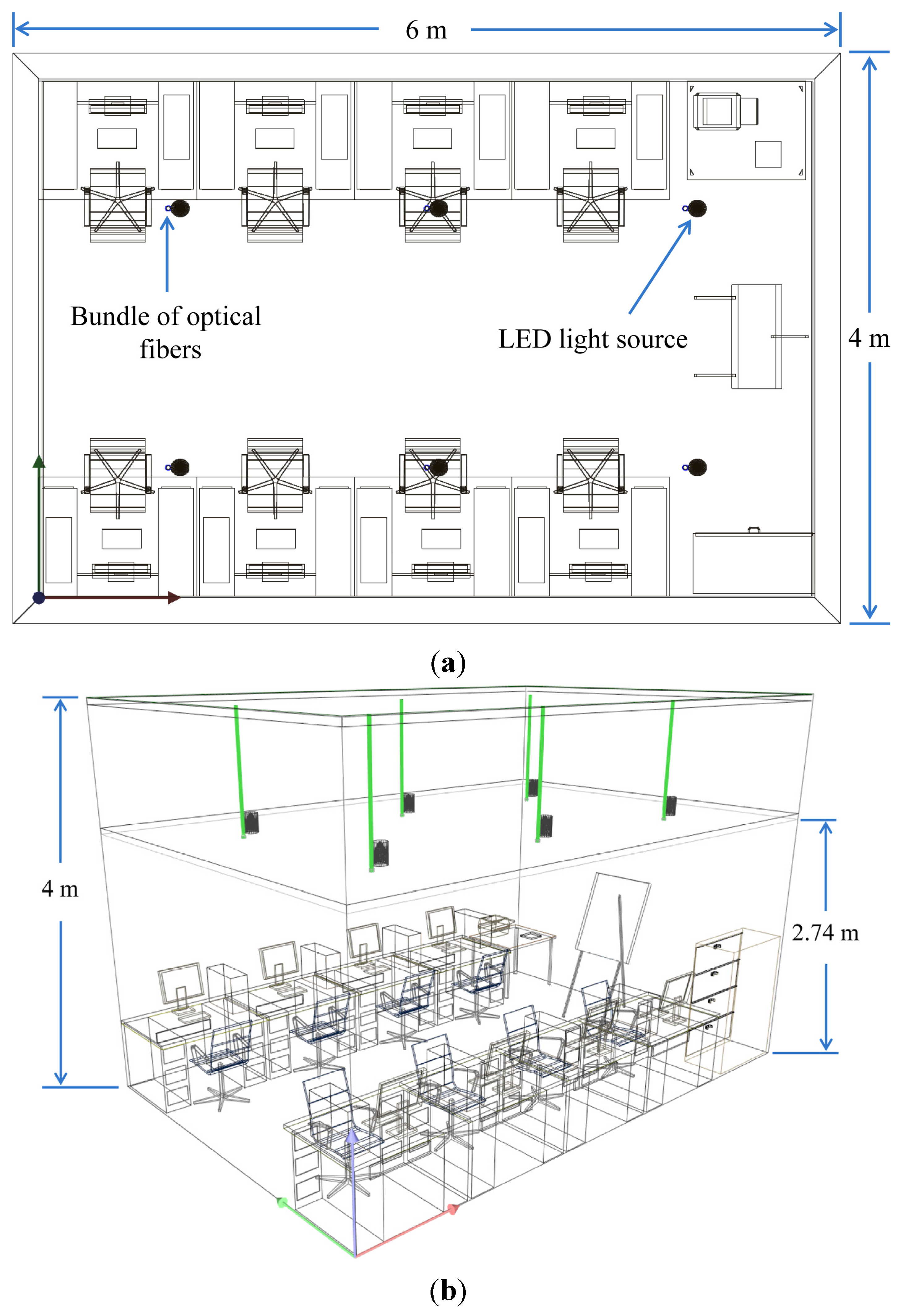
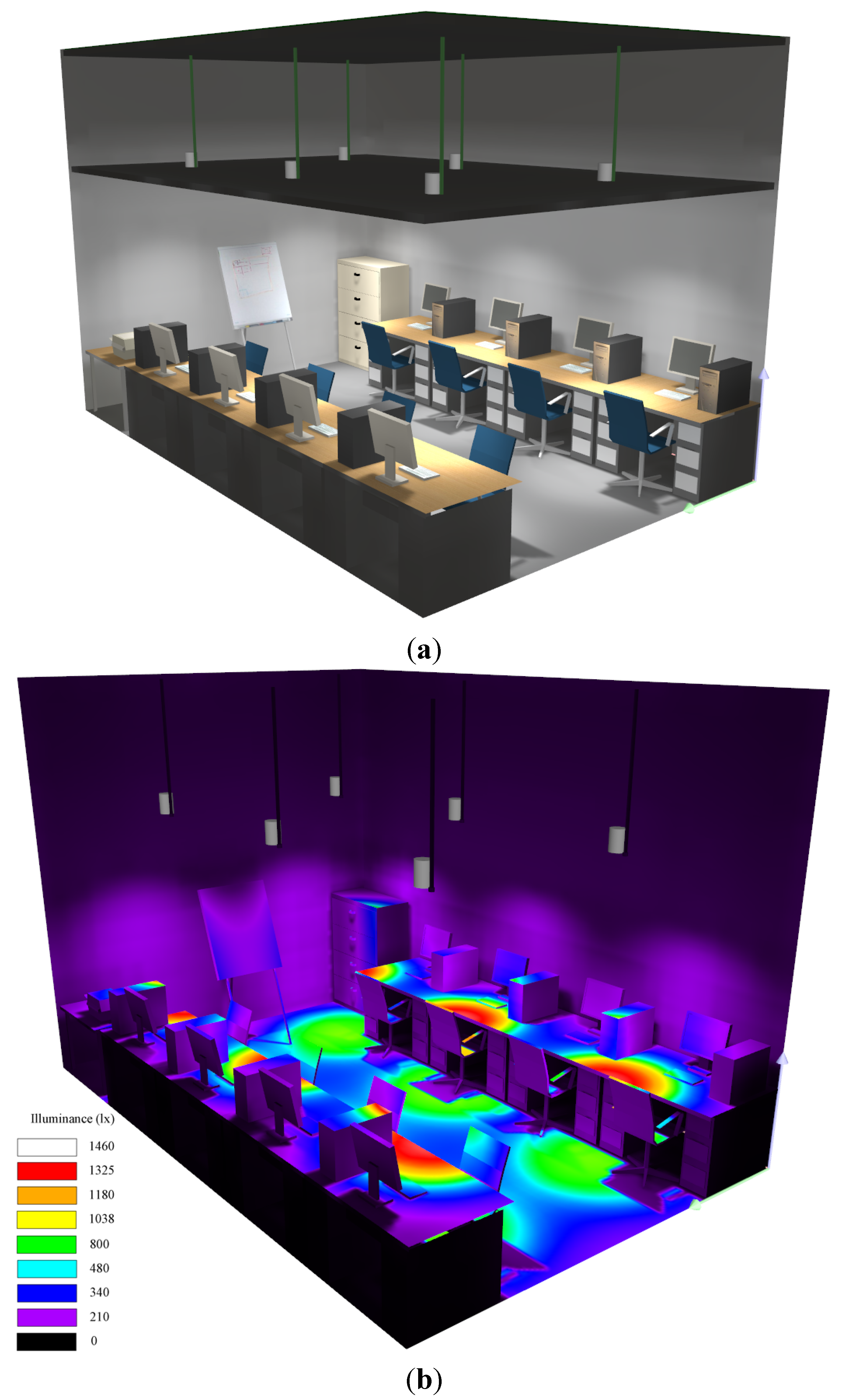
The site (test office) was located at 127° longitude and 37.5° latitude. During the summer solstice, the highest solar altitude (zenith) angle at the site was 76°, and it took place at 12:30, local time. Test office was designed in DIALuxTM software. Dimensions of the office were 6 m long, 4 m wide, and 2.74 m high. Floor plan and section view of the room are shown in Figure 6a,b, respectively. Virtual view of the room’s interior under lighting simulation is shown in Figure 7a. To view the illuminance levels in the room under virtual environment, we show a false color diagram, as shown in Figure 7b. A 2D view of the illuminance levels on the working plane at different times of the day is shown in Figure 8. It can be seen that illuminance at 12:00 is more than the illuminance at 18:00.
Figure 6.
(a) Floor plan of the office and (b) Section view of the interior.
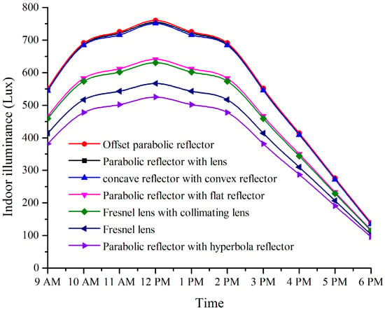
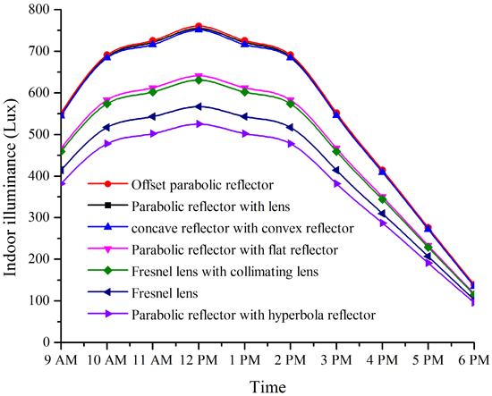
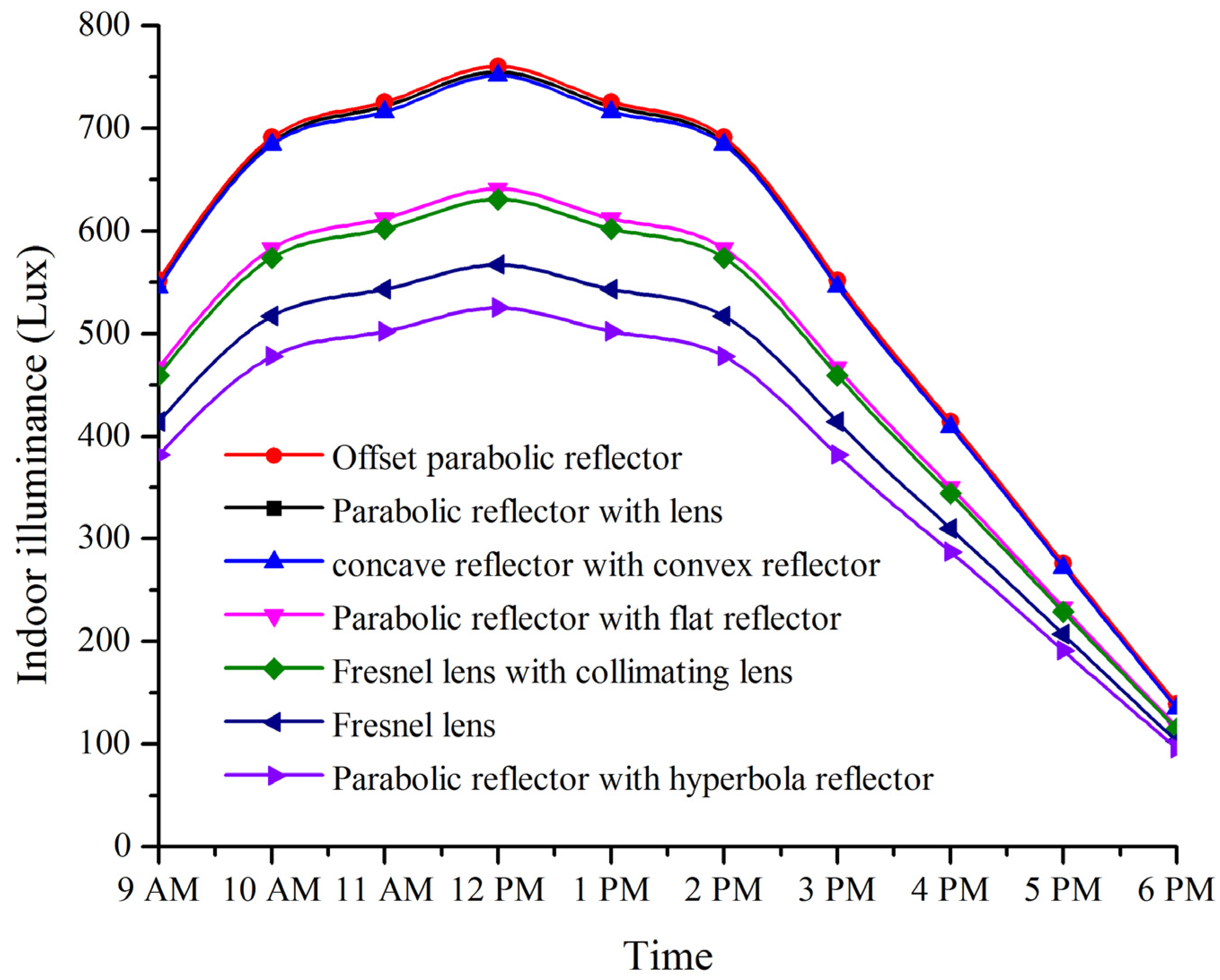
Meanwhile, other daylighting schemes were also simulated to get average illuminance in the interior for comparison. The resulted average illuminance values at different times of the day are plotted in the graph, as shown in Figure 9. Graph shows that two approaches using offset parabolic reflector and concave parabolic reflector with convex parabolic reflector gave similar illuminance like the proposed approach. Other approaches gave low illuminance in the interior. Finally, the proposed approach is better than that of the previous approaches to give high and uniform illumination in the interior.
Figure 7.
Illuminance distribution in the interior (a) lighting view (b) false color view.
The illuminance uniformity of a given space (plane) is calculated by [23]:
where Emin is the minimum level (value) of illuminance and Eavg is the average level (value) of illuminance. We achieved illuminance uniformity of 0.3 and 0.7 on the work plane and floor, respectively.
Figure 8.
Illuminance distribution on the working plane by daylight at (a) 12:00, (b) 13:00, (c) 14:00, (d) 15:00, (e) 16:00, (f) 17:00, and (g) 18:00.
Figure 8.
Illuminance distribution on the working plane by daylight at (a) 12:00, (b) 13:00, (c) 14:00, (d) 15:00, (e) 16:00, (f) 17:00, and (g) 18:00.

Figure 9.
Indoor illuminance on the working plane at different times of the day using different daylighting schemes.
Figure 9.
Indoor illuminance on the working plane at different times of the day using different daylighting schemes.

As lighting has physiological effect on the human body, the most ideal source of illumination is the daylight, with broad emission ranging ultraviolet to infrared. Daylight has correlated color temperature (CCT) of 5500 K, the longest part of the day where it stays the same, but daylight ranges from 2000 to 3000 K at the sunrise [36]. Daylight ranging from warm (<3000 K) to cool light (4000–6500 K) is applied for specific uses in the buildings (e.g., cool light having high contrast compared to warm light is preferred for clear light in kitchens and restroom, while warm light is preferred for indoor lighting, especially in living rooms) [36]. As the proposed daylighting system gives high illuminance value from 10:00 to 14:00, we used OSRAMTM LEDs to reduce changing effect when sunlight is not available as well as to provide same illuminance distribution as that of fiber bundle. In addition, the choice of LEDs depends on specific uses of light in the building (e.g., office, living, etc.) [37].
Lighting energy consumption can be reduced using more efficient lighting sources that produce adequate illuminance using less energy. To attain the required illuminance of 500 lx, which is the minimum requirement [38,39,40,41], in the office when sunlight fell from the required range, we made use of LED light sources. LEDs were placed by feedback from a light sensor. When the daylight was strong, the LEDs were turned off. When illuminance of the daylight was insufficient, LEDs were turned on automatically to meet the deficiency. OSRAMTM LUW W5AM LEDs were used (Table 3) [42]. 24 LEDs were arranged to make a single light source, which illuminated an area of 4 m2. Six LED light sources were arranged to illuminate an area of 24 m2. An average illuminance of 550 lx was achieved through LEDs, as shown in Figure 10.
| Parameters of LED | Value |
|---|---|
| LED Model | LUW W5AM |
| Color, CIE 1931 [43] | Cx = 0.31, Cy = 0.32 |
| Color Temperature | 5700 K |
| Luminous Efficacy | 104 lm/W |
| Luminous Intensity | 35 cd |
Figure 10.
Illuminance distribution on the working plane by LED light.

A control unit was installed to maintain an average illuminance of 500 lx in the interior to provide a constant illuminance at all times [12]. For example, when the average illuminance was 300 lx around 17:00, the remaining illuminance of 200 lx was provided by LEDs through the control unit.
Power consumption of LEDs and energy saving by daylighting are listed in Table 4. We supposed that LEDs were turned on twelve hours without daylight and six hours when daylight was available. An average of more than 50% electric lighting energy can be saved using hybrid daylighting and LED lighting.
| Power Consumption | LEDs (kW·h) | LED and Daylight (kW·h) | Energy Saving (%) |
|---|---|---|---|
| One day | 3.78 | 1.89 | 50 |
| One week | 26.46 | 13.23 | 50 |
| One month | 106.47 | 53.55 | 50 |
| One year | 1279.215 | 644.175 | 50 |
6. Conclusions
In this research, we proposed fiber-based daylighting system in which uniform light was inserted into each optical fiber. The proposed system included light capturing, transmitting, and distributing modules. To capture sunlight, we designed light collecting module using parabolic reflector. A collimating lens was used for uniform illumination over the fiber bundle. We achieved better efficiency in terms of illuminance uniformity and more light flux at the light capturing stage than the previous approaches.
There are three issues in our previous approach [13]: shadow on the fiber bundle, difficult to manufacture and align collimating reflector, and non-uniform illumination through diffuser. In this approach, we reduced shadow over fiber bundle and used collimating lens instead of collimating reflector, which is easy for manufacturing process and aligning purpose. To solve third problem, an optical lens structure was used to spread light on the working plane uniformly. As a result, we achieved uniform illumination at the capturing and distributing stages, and interior area was illuminated with uniform illumination.
A comparative analysis was also carried out for the daylighting performance of the current approach with the previous approaches [24,25,26,27]. It was found that current results that include uniform illumination and high illuminance are better than that of previous approaches. Furthermore, we introduced a hybrid system, which helps to fulfill the minimum required illuminance in the interior by combining daylight and LED light.
To investigate the system, we considered a test office. The system was developed and applied to the test office. Results have shown that the interior of the office was illuminated uniformly with an average illuminance of more than 500 lx at all times. An average of more than 50% electric lighting energy can be saved using hybrid approach.
In the future, we will improve light uniformity in the interior of the building by designing a microstructure diffuser, which would reduce “hot spot” directly under the optical fiber (light source). In addition, glare on the ceiling due to optical fiber with luminance values in high contrast will be reduced.
Acknowledgments
This research is supported by NSC MOST103-2221E011047-, 104-2218E011003, 102-2923I011002MY4, National Taiwan University of Science and Technology (NTUST) Top University Grant Project, EU FP-7 Cost-Effective Tools for Better Indoor Environment in Retrofitted Energy Efficient Buildings (CETIEB) Project, EU FP-7 EcoShopping Project and Bureau of Energy, Ministry of Economic Affairs, Energy Technology Program for Academia under Grant No. 102-E0608.
Author Contributions
Irfan Ullah conducted simulation and made the manuscript, and Allen Jong-Woei Whang supervised this study.
Conflicts of Interest
The authors declare no conflict of interest.
References
- Marks, F.M. Letter to the Editors: Lighting for Different Healthcare Settings. Health Environ. Res. Des. J. 2013, 6, 166–168. [Google Scholar] [CrossRef]
- Annual Energy Outlook 2012; U.S. Energy Information Administration (EIA): Washington, DC, USA, 2012.
- 2010 Buildings Energy Data Book; U.S. Department of Energy: Washington, DC, USA, 2010.
- Martirano, L.A. Smart lighting control to save energy. In Proceedings of the 2011 IEEE 6th International Conference on Intelligent Data Acquisition and Advanced Computing Systems (IDAACS), Prague, Czech Republic, 15–17 September 2011; pp. 132–138.
- Ossa, A.; Gottfried, D.A.; Walsh, T.; Simon, L.N. Sustainable Building Technical Manual: Green Building, Design, Construction and Operations; U.S. Public Technology Inc.: Los Angeles, CA, USA, 1996. [Google Scholar]
- Green Building Rating Systems—Draft Recommendations for a U.S. Rating System; U.S. Green Building Council: Bethesda, MD, USA, 1995.
- CIBSE Code for Interior Lighting, 1994; Chartered Institution of Building Services Engineers (CIBSE): London, UK, 1994.
- Nilsson, A.M.; Jonsson, J.C.; Roos, A. Spectrophotometric measurements and ray tracing simulations of mirror light pipes to evaluate the color of the transmitted light. Solar Energy Mater. Solar Cells 2014, 124, 172–179. [Google Scholar] [CrossRef]
- Ullah, I.; Shin, S. Concept of solar tower for daylighting in multi-floor buildings. J. Green Sci. Technol. 2013, 1, 79–84. [Google Scholar] [CrossRef]
- Oh, S.J.; Chun, W.; Riffat, S.B.; Jeon, Y.I.; Dutton, S.; Han, H.J.; Tsuei, C.; Sun, W.; Kuo, C. Computational analysis on the enhancement of daylight penetration into dimly lit spaces: Light tube vs. fiber optic dish concentrator. Build. Environ. 2012, 59, 261–274. [Google Scholar] [CrossRef]
- Su, Y.; Han, H.; Riffat, S.B.; Patel, N. Evaluation of a lightwell design for multi-storey buildings. Int. J. Energy Res. 2010, 34, 387–392. [Google Scholar] [CrossRef]
- Görgülü, S.; Ekren, N. Energy saving in lighting system with fuzzy logic controller which uses light-pipe and dimmable ballast. Energy Build. 2013, 61, 172–176. [Google Scholar] [CrossRef]
- Ullah, I.; Shin, S. Development of optical fiber-based daylighting system with uniform illumination. J. Opt. Soc. Korea 2012, 16, 247–255. [Google Scholar] [CrossRef]
- Ullah, I.; Shin, S. Uniformly illuminated efficient daylighting system. Smart Grid Renew. Energy 2013, 4, 161–166. [Google Scholar] [CrossRef]
- Wong, I.; Yang, H. Cost study on remote source solar lighting system in high-rise residential buildings in Hong Kong. Build. Environ. 2013, 67, 231–239. [Google Scholar] [CrossRef]
- Han, H.J.; Riffat, S.B.; Lim, S.H.; Oh, S.J. Fiber optic solar lighting: Functional competitiveness and potential. Solar Energy 2013, 94, 86–101. [Google Scholar] [CrossRef]
- Lingfors, D.; Volotinen, T. Illumination performance and energy saving of a solar fiber optic lighting system. Opt. Express 2013, 21, A642–A655. [Google Scholar] [CrossRef] [PubMed]
- Núñez, R.; Antón, I.; Sala, G. Hybrid lighting-CPV, a new efficient concept mixing illumination with CPV. Opt. Express 2013, 21, 4864–4874. [Google Scholar] [CrossRef] [PubMed]
- Song, J.; Yang, Y.; Zhu, Y.; Jin, Z. A high precision tracking system based on a hybrid strategy designed for concentrated sunlight transmission via fibers. Renew. Energy 2013, 57, 12–19. [Google Scholar] [CrossRef]
- Sapia, C. Daylighting in buildings: Developments of sunlight addressing by optical fiber. Solar Energy 2013, 89, 113–121. [Google Scholar] [CrossRef]
- Mayhoub, M.S. Innovative daylighting systems’ challenges: A critical study. Energy Build. 2014, 80, 394–405. [Google Scholar] [CrossRef]
- Sharp, F.; Lindsey, D.; Dols, J.; Coker, J. The use and environmental impact of daylighting. J. Clean. Prod. 2014, 85, 462–471. [Google Scholar] [CrossRef]
- Ullah, I.; Shin, S. Highly concentrated optical fiber-based daylighting systems for multi-floor office buildings. Energy Build. 2014, 72, 246–261. [Google Scholar] [CrossRef]
- Feuermann, D.; Gordon, J.M.; Huleihil, M. Solar fiber-optic mini-dish concentrators: First experimental results and field experience. Solar Energy 2002, 72, 459–472. [Google Scholar] [CrossRef]
- Kribus, A.; Zik, O.; Karni, J. Optical fibers and solar power generation. Solar Energy 2000, 68, 405–416. [Google Scholar] [CrossRef]
- Kandilli, C.; Ulgen, K. Review and modelling the systems of transmission concentrated solar energy via optical fibres. Renew. Sustain. Energy Rev. 2009, 13, 67–84. [Google Scholar] [CrossRef]
- Gilmore, V.E. Sun flower over Tokyo. In Popular Science; Bonnier Corporation: Winter Park, FL, USA, 1988. [Google Scholar]
- Alcini, C.M.; Schiavoni, S.; Asdrubali, F. Simulation of daylighting conditions in a virtual underground city. J. Daylighting 2015, 2, 1–11. [Google Scholar] [CrossRef]
- Malacara, D. Optical Shop Testing; John Wiley & Sons: New York, NY, USA, 1992. [Google Scholar]
- Keiser, G. Optical Fiber Communications, 3rd ed.; McGraw-Hill: New York, NY, USA, 2000. [Google Scholar]
- Wang, C.; Abdul-Rahman, H.; Rao, S.P. Daylighting can be fluorescent: Development of a fiber solar concentrator and test for its indoor illumination. Energy Build. 2010, 42, 717–727. [Google Scholar] [CrossRef]
- Wang, G.; Wang, L.; Li, F.; Kong, D. Design of optical element combining Fresnel lens with microlens array for uniform light-emitting diode lighting. J. Opt. Soc. Am. A 2012, 29, 1877–1884. [Google Scholar] [CrossRef] [PubMed]
- Ullah, I. Development of Fresnel-based concentrated photovoltaic (cpv) system with uniform irradiance. J. Daylighting 2014, 1, 2–7. [Google Scholar] [CrossRef]
- Jenkins, F.A.; White, H.E. Fundamental of Optics; McGraw-Hill: New York, NY, USA, 1957. [Google Scholar]
- Mahajan, V.N. Optical Imaging and Aberrations, Part 1: Ray Geometrical Optics; SPIE Press: Washington, DC, USA, 1998. [Google Scholar]
- Kim, Y.H.; Arunkumar, P.; Park, S.H.; Yoon, H.S.; Im, W.B. Tuning the diurnal natural daylight with phosphor converted white LED—Advent of new phosphor blend composition. Mater. Sci. Eng. 2015, 193, 4–12. [Google Scholar] [CrossRef]
- Ge, A.; Qiu, P.; Cai, J.; Wang, W.; Wang, J. Hybrid daylight/light-emitting diode illumination system for indoor lighting. Appl. Opt. 2014, 53, 1869–1873. [Google Scholar] [CrossRef] [PubMed]
- Light and Lighting—Lighting of Work Places, Part 1: Indoor Work Places; BS EN 12464-1:2002; British Standards Institution: London, UK, 2002.
- Tian, M.; Su, Y. An improvement to calculation of lighting energy requirement in the European Standard EN 15193:2007. J. Daylighting 2014, 1, 16–28. [Google Scholar] [CrossRef]
- Verso, V.R.M.L.; Fregonara, E.; Caffaro, F.; Morisanov, C.; Peiretti, G.M. Daylighting as the driving force of the design process: From the results of a survey to the implementation into an advanced daylighting project. J. Daylighting 2014, 1, 36–55. [Google Scholar] [CrossRef]
- Bellia, L.; Fragliasso, F.; Pedace, A. Evaluation of daylight availability for energy savings. J. Daylighting 2015, 2, 12–20. [Google Scholar] [CrossRef]
- OSRAMTM, LUW W5AM Datasheet. Available online: http://www.osram-os.com/Graphics/XPic6/00089171_0.pdf/LUW%20W5AM.pdf (accessed on 1 January 2014).
- Smith, T.; Guild, J. The C.I.E. colorimetric standards and their use. Trans. Opt. Soc. 1931, 33, 73–134. [Google Scholar] [CrossRef]
© 2015 by the authors; licensee MDPI, Basel, Switzerland. This article is an open access article distributed under the terms and conditions of the Creative Commons Attribution license (http://creativecommons.org/licenses/by/4.0/).
Share and Cite
MDPI and ACS Style
Ullah, I.; Whang, A.J.-W. Development of Optical Fiber-Based Daylighting System and Its Comparison. Energies 2015, 8, 7185-7201. https://doi.org/10.3390/en8077185
AMA Style
Ullah I, Whang AJ-W. Development of Optical Fiber-Based Daylighting System and Its Comparison. Energies. 2015; 8(7):7185-7201. https://doi.org/10.3390/en8077185
Chicago/Turabian StyleUllah, Irfan, and Allen Jong-Woei Whang. 2015. "Development of Optical Fiber-Based Daylighting System and Its Comparison" Energies 8, no. 7: 7185-7201. https://doi.org/10.3390/en8077185