1. Introduction
A microgrid is a small-scale power system, which can operate in two modes: grid-connected mode and islanded mode. Generally, a microgrid is comprised of distributed energy resources (DERs), distributed energy storage systems, and loads [
1,
2]. DERs such as diesel generators, natural gas generators, and fuel cells are placed along with the loads. Besides, renewable energy sources such as solar and wind powers can alleviate the environmental problems caused by burning fossil fuels. However, the drawback of renewable energy sources is the power fluctuations due to the stochastic nature of wind and solar power. The fluctuations must be compensated to meet the power-quality requirements [
3,
4,
5].
In order to reduce wind or solar power fluctuations, short-term energy storage systems such as superconducting magnetic energy storage (SMES) systems, electrical double-layer capacitors (EDLCs), flywheel energy storage (FES) systems, as well as long-term energy storage systems such as battery energy storage systems (BESS) are installed in the microgrid. A fast response is necessary to compensate for the fluctuations in wind power, therefore a BESS might not be a good alternative, as it charges and discharges slowly. A BESS is often used in the microgrid equipped with a solar photovoltaic generator [
6,
7]. FES systems, SMES systems and EDLCs can be used for smoothing the power generated by wind, given their fast response and efficiency [
8,
9,
10,
11,
12,
13,
14,
15,
16,
17,
18,
19,
20,
21]. However, the use of SMES systems and EDLCs is still limited, due to the high initial investment and maintenance costs involved [
13]. This study will focus on FES systems and wind power to show how the fluctuations in wind power are handled by the proposed FES system.
Of late, using an FES system in microgrids is being explored as a potential solution for improving the power quality, as such a system is highly reliable, has short response times, long lives, and low overall costs. The use of an FES system to improve the degree of integration of wind power in alternating (AC) microgrids has already been investigated [
14,
15,
16]. The FES system can control not only the frequency but also the voltage of the microgrid during islanded operation. In the grid-connected mode, the FES system is used to compensate for wind power fluctuations. In addition, the FES system can be coupled with the wind generator using a doubly fed induction generator [
17,
18,
19,
20], for smoothing the wind power. Further, in order to improve the performance of FES systems in direct current (DC) microgrids, Chang has suggested introducing an active disturbance rejection control [
21].
The main components of an FES system are a rotating mass, a motor-generator machine, and converters. Three types of motor-generator machine can be used: a permanent-magnet machine, an induction machine used as a doubly fed induction machine (DFIM), or a switched reluctance machine [
22,
23,
24]. FES systems based on a permanent-magnet machine or a switched reluctance machine require converters with significantly higher power ratings than FES systems based on a DFIM. As a result, the overall cost of FES systems based on a permanent-magnet machine or a switched reluctance machine is higher than that of those based on a DFIM. In 1996, the World’s first low-speed FES system based on a DFIM was installed and commissioned in Japan at the Chujowan substation of the Okinawa Electric Power Company [
25]. This FES system, which has an energy rating of 200 MJ and power of 20 MW, is used to control the frequency of the utility grid. Thus, very large FES systems can be used in microgrids to successfully regulate the frequency. However, the cost of such FES systems is very high, owing to cost of their components such as the mass, shaft, motor/generator, bearings, cooling unit, and containment unit. A small FES system that stores a small fraction of the energy can be suitable for handling wind power fluctuations in grid-connected mode because a relatively small amount of energy is required. However, it might be inappropriate to handle frequency of microgrid in islanded mode due to the need for a larger amount of energy. To overcome this problem, in this paper, we propose a new FES system based on a DFIM and a battery for use in microgrids. This FES system can control its power to compensate for fluctuations in wind power in grid-connected mode, in addition to controlling the frequency and voltage of the microgrid in islanded mode. The efficacy of the proposed FES system is verified via simulations in the MATLAB/Simulink environment.
The rest of this paper is organized as follows:
Section 2 introduces conventional FES system and the proposed FES system. In
Section 3, the proposed FES control system, which has a two-level control scheme, is described.
Section 4 describes the microgrid system used to test the performance of the proposed FES system. In
Section 5, the simulation results for three different scenarios are described. Finally, the main conclusions of the study are summarized in
Section 6.
2. Proposed FES System
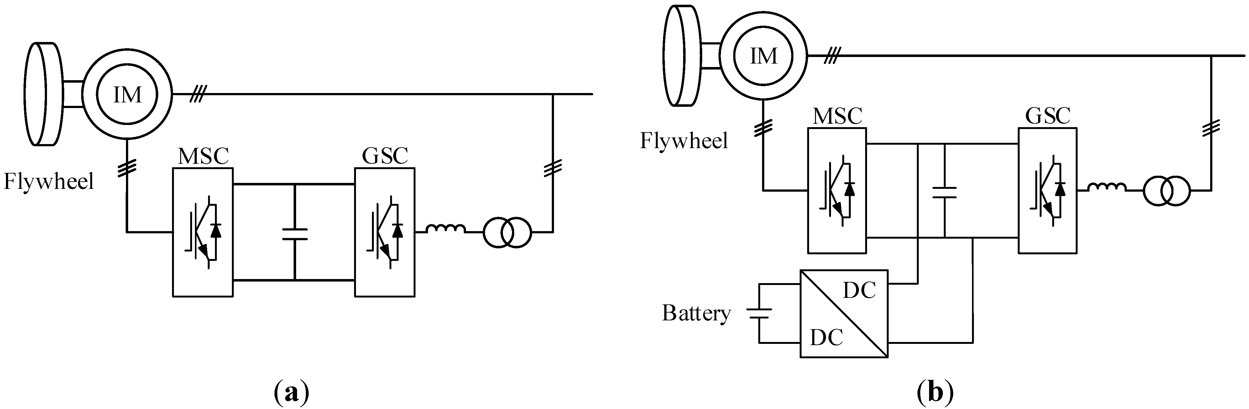
A conventional FES system based on a DFIM and the proposed FES system are shown in
Figure 1. The conventional FES system consists of a flywheel, an induction machine that acts as both a motor and a generator, and a back-to-back converter system. The difference between the proposed FES system and the conventional one is that the former has an additional battery with a boost-buck DC/DC converter connected to the DC-link back-to-back converter system. The back-to-back converter system is divided into two components: a machine-side converter (MSC) and a grid-side converter (GSC). The MSC is connected to the rotor winding while the GSC is connected to the grid through a filter and a transformer.
Figure 1.
FES systems: (a) conventional FES system; (b) proposed FES system.
Figure 1.
FES systems: (a) conventional FES system; (b) proposed FES system.
The operating principle of the FES system is that a rotating mass can be used to store and retrieve energy. The flywheel, which is connected to an induction machine, is a mass with a high inertia. Thus, in this study, an induction machine with a high inertia was used to model the FES system in MATLAB/Simulink. The energy stored by the FES system is in the form of kinetic energy,
E, which can be represented by Equation (1) [
26]:
where
ω is the rotational speed of the FES system and
J is its moment of inertia.
The available energy stored in the FES system, ∆
E, is represented by Equation (2):
where
ωmax and
ωmin are the maximum and minimum speeds of the FES system, respectively.
The power exchanged with the stator circuit and the electrical torque of the induction machine can be expressed as follows [
27]:
where
ωr is the electrical angular velocity (
),
is the stator flux linkage,
Lm is the magnetizing inductance,
Ls is the stator inductance, and
is the conjugate of the rotor current.
In this study, the rotor reference frame was used to convert the abc-frame into a dq-frame using the Clarke and Park transformation. As a result, the rotor current represented in the dq-frame is given by the following expression [
28]:
Substituting
iqdr from Equation (5) in Equations (3) and (4), we get:
The real and reactive powers of the stator are given by:
It can be seen from Equations (7)–(9) that the electrical torque and stator power of an induction machine can be controlled by the rotor current.
4. Test Microgrid
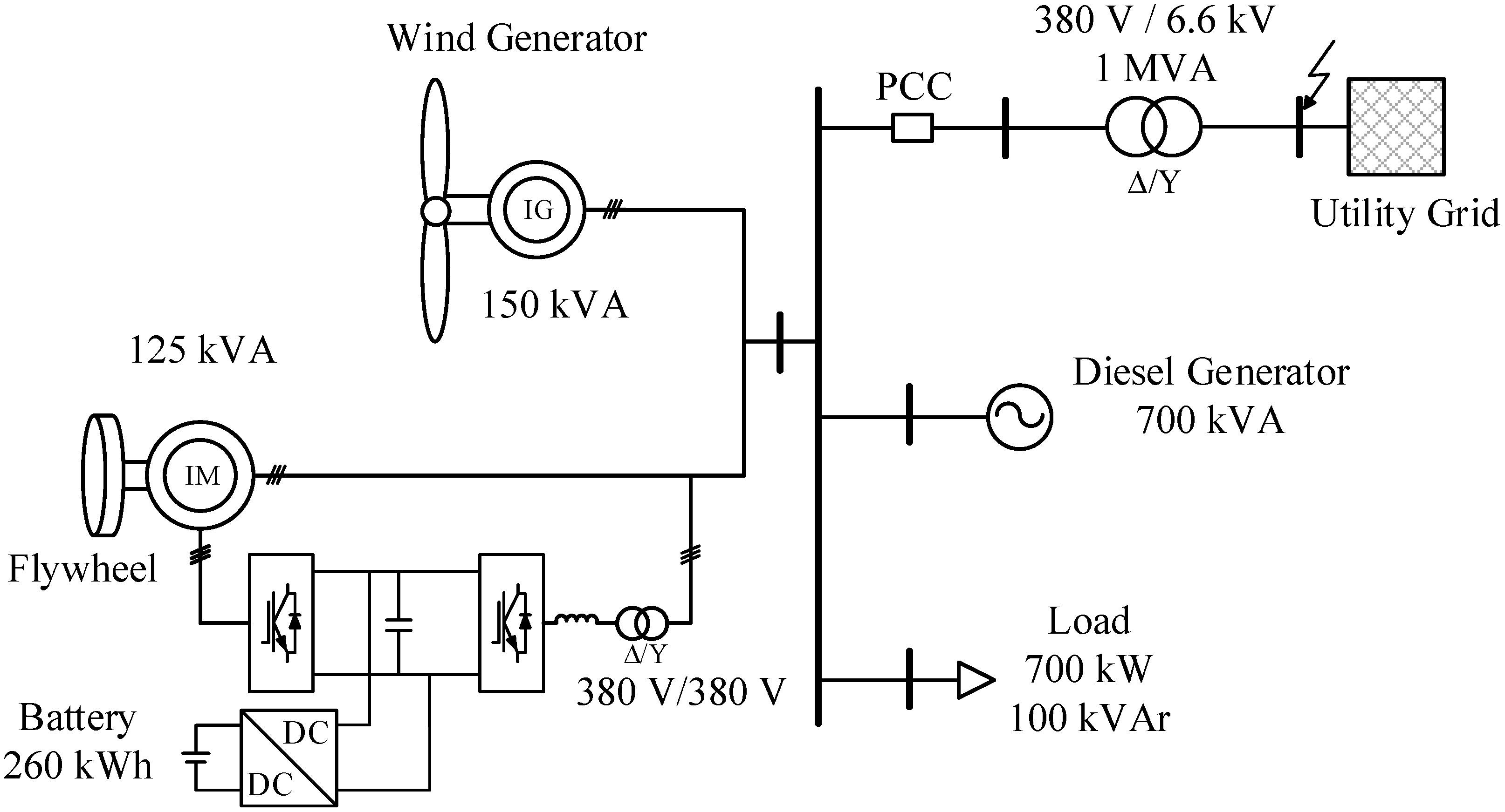
The test microgrid system (
Figure 5) used in the study included several components: a diesel generator, a consumer load, a wind generator, and an FES system. In this study, for the sake of simplicity, we used a fixed-speed wind energy conversion system (WECS) [
32].
Figure 5.
Configuration of the microgrid.
Figure 5.
Configuration of the microgrid.
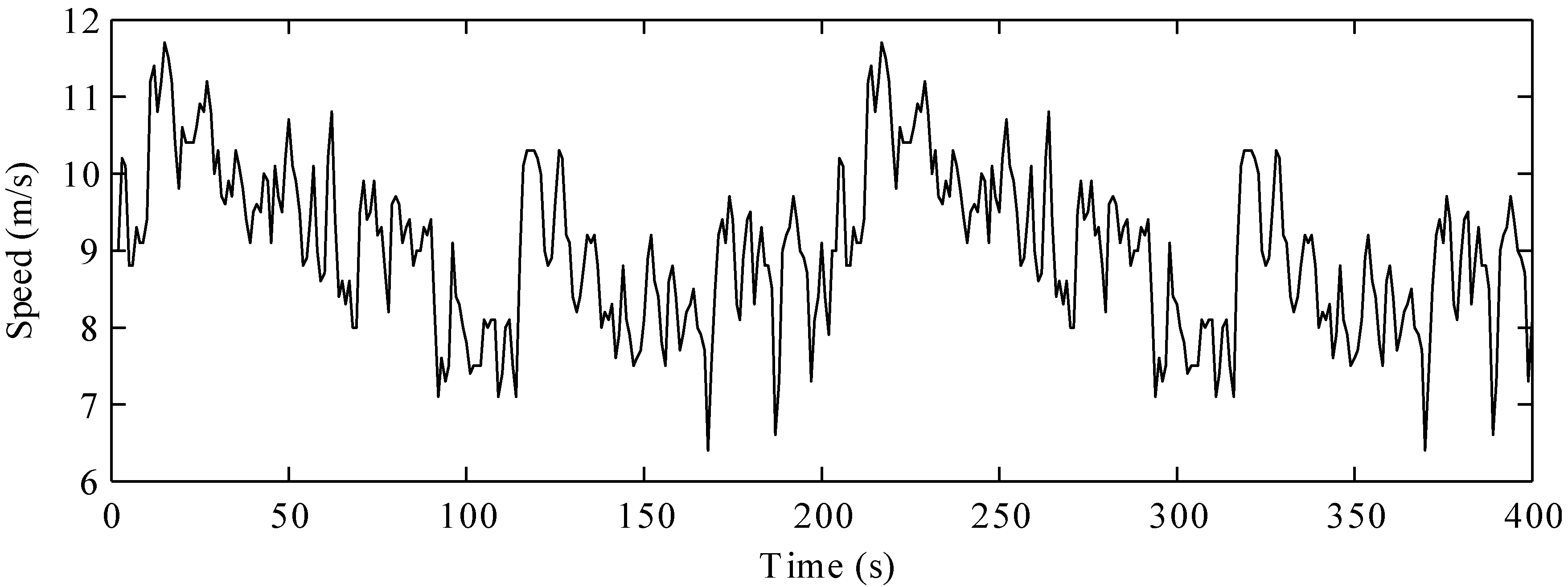
The output power of the wind generator varies with the wind speed.
Figure 6 shows the actual wind speed data; the mean speed was 9 m/s. The output power of the wind generator corresponding to the mean wind speed was 50 kW. An FES system with a speed range of 2520–4680 rpm was installed near the wind generator. According to Equation (2), the available energy stored in the FES system, which had a moment of inertia,
J, of 37.6 kgm2, was 3.2 MJ. In order to eliminate the harmonics generated from the GSC, a filter and a ∆-
Y transformer are installed on the GSC. In the proposed FES system, a 600-V battery is connected to the capacitor through the bi-directional converter, in order to regulate the DC-link voltage at 2200 V. The main power supply is from the diesel generator, which has a rating of 700 kVA. Additional power is supplied from the wind generator and the FES system.
Figure 6.
Actual wind speed data.
Figure 6.
Actual wind speed data.
The microgrid is connected to the utility grid by a step-up transformer. The circuit breaker is placed at the point of common coupling (PCC) to connect or disconnect the microgrid with the utility grid. The circuit breaker is opened when the protection system detects a severe fault or strong oscillations in the power on the utility grid side.
5. Simulation Results
Three scenarios were considered to validate the performance of the proposed FES system. In the first scenario, the microgrid operates in the grid-connected mode; this is carried out to test the performance of the FES system in the smoothing-of-wind-power mode. The second scenario simulates a case where a severe fault occurs on the utility grid side. Thus, the microgrid operates in the islanded mode. The FES system has to maintain the frequency as well as the voltage of the microgrid. Finally, the third scenario considers the rating of the FES system, which is reduced by decreasing its moment of inertia. The conventional FES system is also simulated for a comparison with the proposed FES system. The simulations are performed in the MATLAB/Simulink environment.
5.1. Smoothing-of-Wind-Power Mode
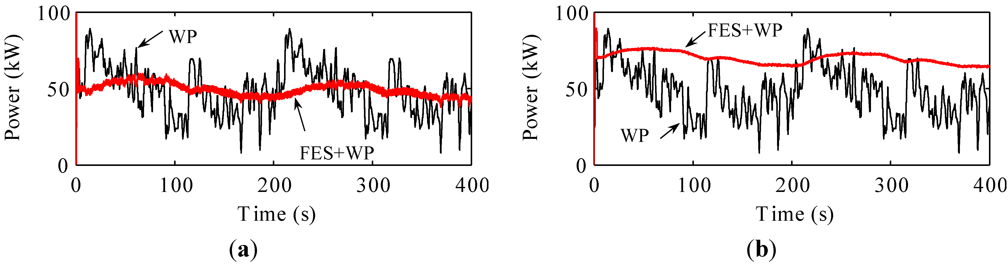
In the grid-connected mode, the MSC controls the real power of the FES system, in order to compensate for the fluctuations in the wind power. The wind power fluctuates with the wind speed. However, by effectively compensating for the variations in the wind power, the total real power of the wind generator and the FES system can be transmitted stably to the microgrid without strong fluctuations, as shown in
Figure 7.
Figure 7.
FES power and wind power: (a) the conventional FES system; (b) the proposed FES system.
Figure 7.
FES power and wind power: (a) the conventional FES system; (b) the proposed FES system.
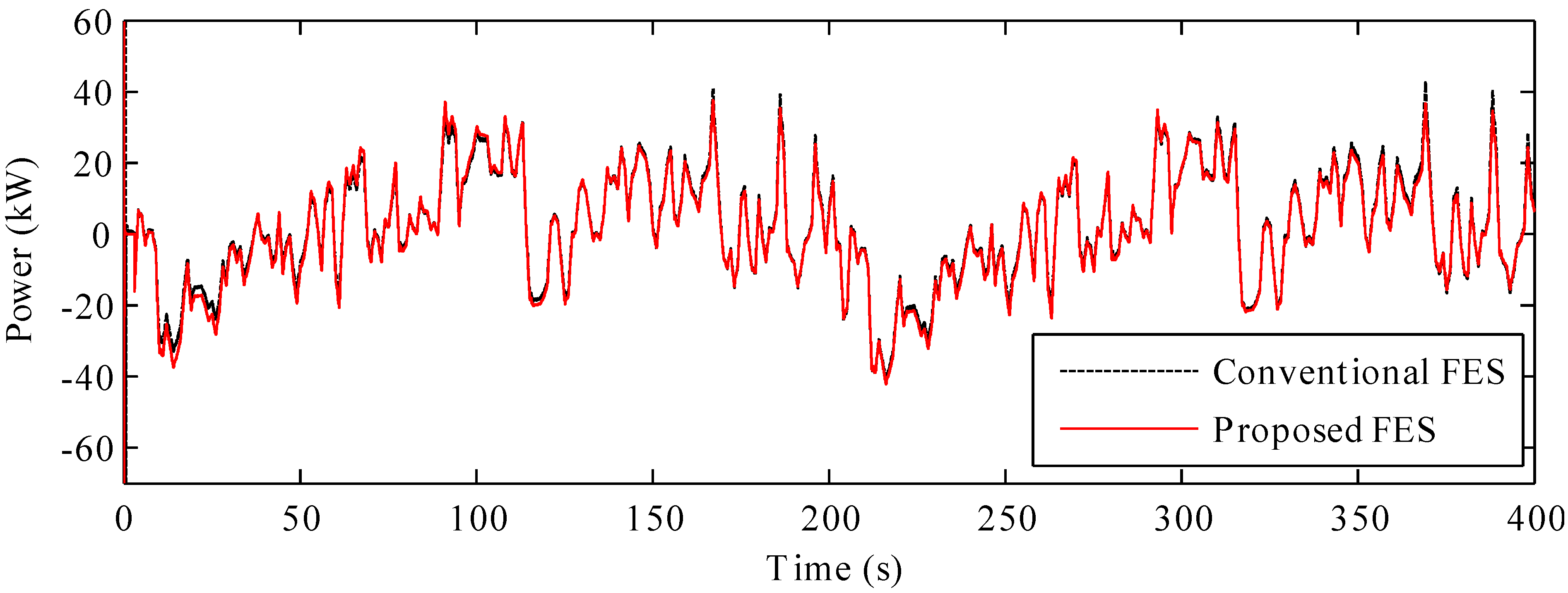
For instance, at approximately 20 s, the wind speed increases to a level above the mean speed, resulting in an increase in the wind power. At this point, the FES system is in the charging mode, in order to absorb the generated wind power. At approximately 100 s, the wind power decreases owing to a drop in the wind speed. Thus, the FES system is in the discharging mode to compensate for the drop in the wind power. As a result, because of the charging and discharging of the FES system, as shown in
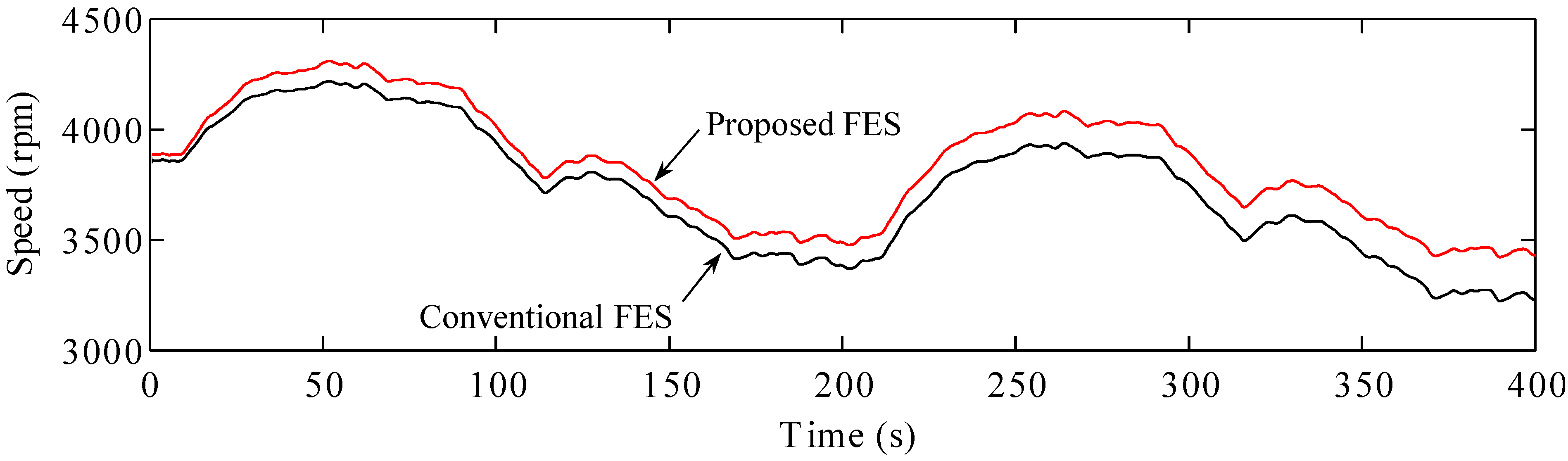
Figure 8, the fluctuations in the wind power can be reduced. The speed of the FES system, shown in
Figure 9, depends on its charging and discharging modes. It can be seen that the speed of the FES system is always in the allowable range.
Finally, both the conventional FES system and the proposed FES system exhibited good performance with respect to the smoothing of wind power. However, for the proposed FES system, the total wind power and the FES power are higher than those of the conventional FES system, because of the constant output power of the GSC.
Figure 8.
Stator powers of the FES systems.
Figure 8.
Stator powers of the FES systems.
Figure 9.
Speeds of the FES systems.
Figure 9.
Speeds of the FES systems.
5.2. Frequency Control and Voltage Control Modes
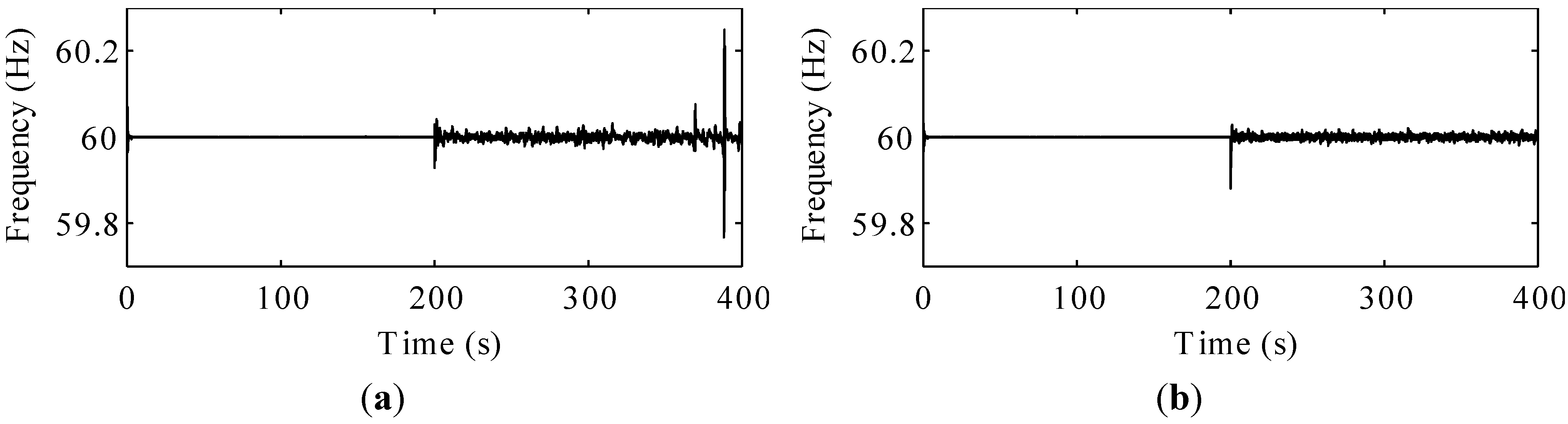
A three-phase-to-ground fault is applied at 200 s on the high-voltage side of a transformer connected to the utility grid. The fault is cleared after five cycles by opening the circuit breaker placed at the PCC. Thus, the microgrid is operated in the islanded mode.
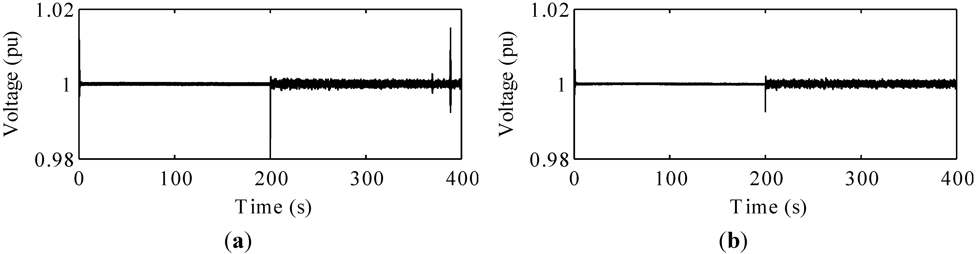
Figure 10 shows the frequency and
Figure 11 shows the AC voltage of the microgrid. The frequency is controlled by the MSC in the case of the conventional FES system and the GSC in the case of the proposed FES system. The voltage is controlled by the MSC in both the conventional FES system and the proposed one. It can be seen that both systems can stably control the frequency as well as the AC voltage of the microgrid.
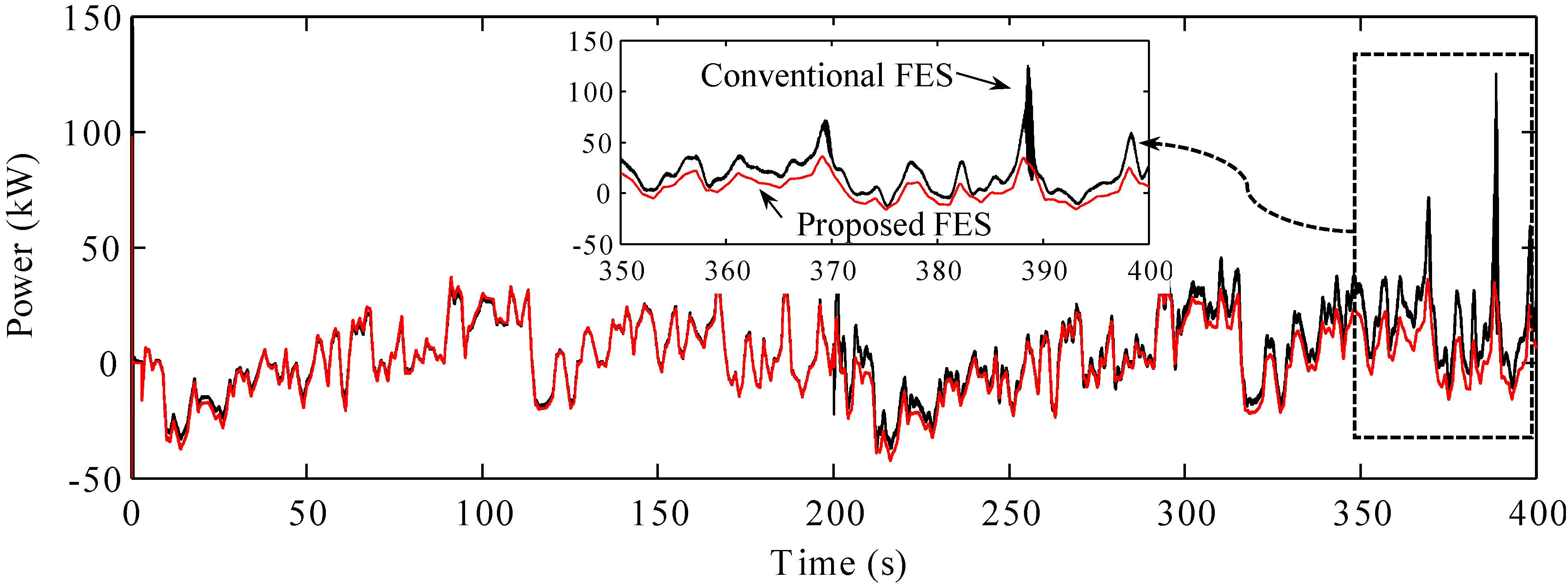
However, in case of the conventional FES system, at approximately 370 s, dramatic changes occur in the frequency and voltage, owing to a sudden fall in the wind speed. These changes can be explained on the basis of the action of the FES system. The sudden drop in the wind speed leads to a marked increase in the FES power, in order to compensate for the drop in the wind power, as shown in
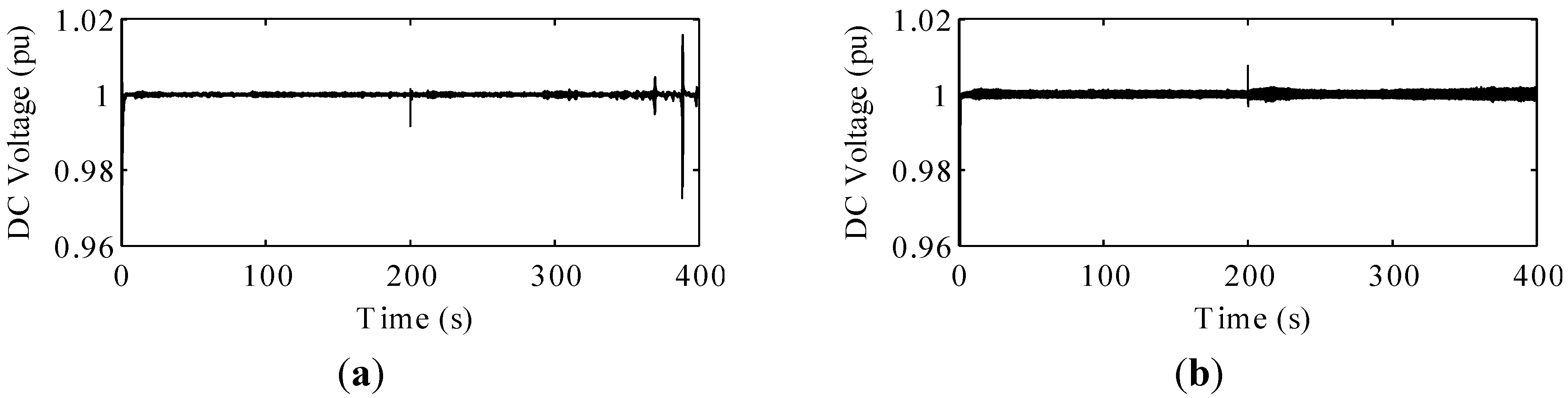
Figure 12. This action of the FES system causes a sudden change in the DC-link voltage of the back-to-back converter (
Figure 13a). The MSC controlled the FES power is affected directly by this sudden change in the DC-link voltage. As a result, the imbalance between the power supply and the power demand causes a dramatic change in the frequency and voltage of the microgrid.
Figure 10.
Frequencies of the microgrid system: (a) microgrid with the conventional FES system; (b) microgrid with the proposed FES system.
Figure 10.
Frequencies of the microgrid system: (a) microgrid with the conventional FES system; (b) microgrid with the proposed FES system.
Figure 11.
Voltages of the microgrid system: (a) microgrid with the conventional FES system; (b) microgrid with the proposed FES system.
Figure 11.
Voltages of the microgrid system: (a) microgrid with the conventional FES system; (b) microgrid with the proposed FES system.
Figure 12.
Stator powers of the FES systems.
Figure 12.
Stator powers of the FES systems.
In comparison, in the case of the proposed FES system, the DC-link voltage is controlled independently by the battery-side converter, as shown in
Figure 13b. Thus, the DC-link voltage is not affected significantly by the dramatic change in the FES power. The MSC control system coordinates with the GSC control system, allowing for stable control of the frequency and voltage of the microgrid. Although the ripple in the DC-link voltage of the proposed FES system is higher than for the conventional FES system, owing to the DC-DC converter in the proposed FES system, the DC-link voltage of the proposed FES system is still in the desirable range.
Figure 13.
DC-link voltages of the back-to-back converter: (a) the conventional FES system; (b) the proposed FES system.
Figure 13.
DC-link voltages of the back-to-back converter: (a) the conventional FES system; (b) the proposed FES system.
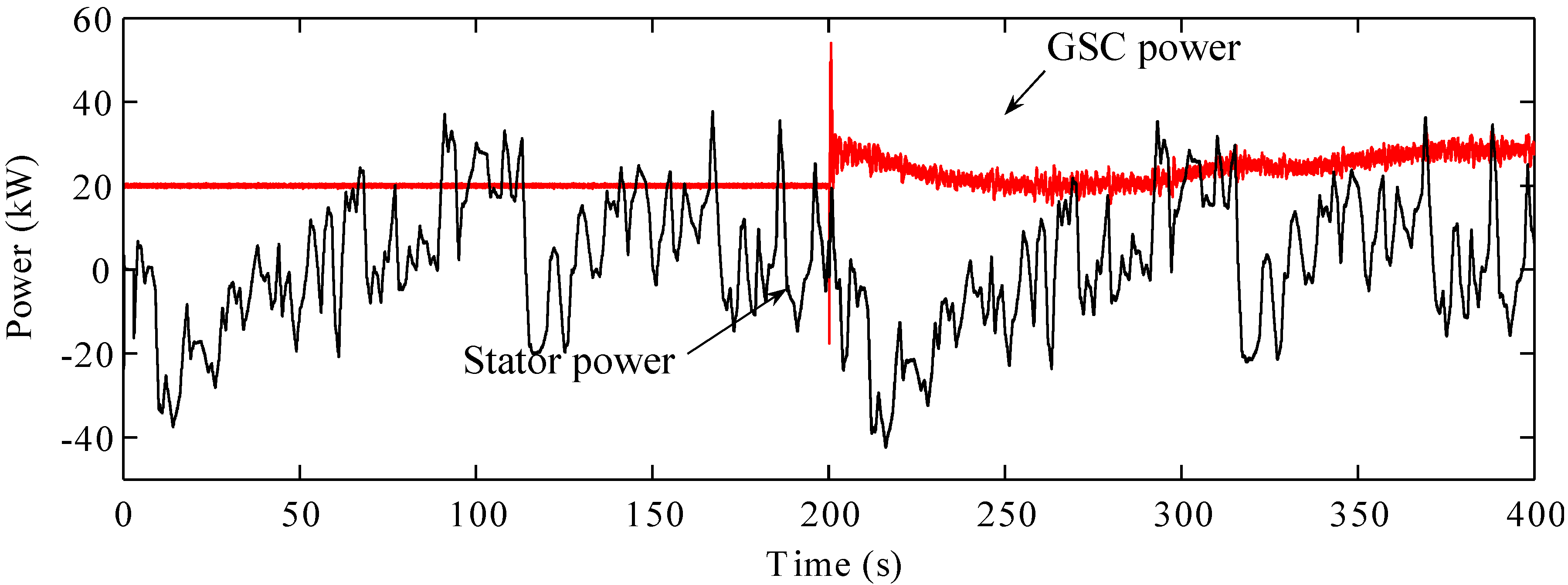
Figure 14 shows the stator and GSC powers of the proposed FES system. As mentioned in
Section 3.3, the MSC controls the stator power to compensate for the wind power during both the grid-connected mode and the islanded mode. The fluctuations in the stator power represent the charging and discharging of the FES system.
Figure 14.
Stator power and GSC power of the proposed FES system.
Figure 14.
Stator power and GSC power of the proposed FES system.
The FES system is a short-term energy storage system that can be frequently charged and discharged. In comparison, the GSC controls the GSC power stored in the battery during the grid-connected mode as well as the frequency during the islanded mode. The frequency of the microgrid represents the relationship between the power supply and the power demand. Strong fluctuations in the frequency represent significant differences in the suppliable power and the power demand. The GSC control system coordinates with the MSC control system in the frequency-control mode. After the smoothing of the wind power, the imbalance between the power supply and the power demand is compensated for by the GSC power. Thus, the frequency of the microgrid can be controlled in a stable manner. The variations in the GSC power reflect the charging and discharging of modes the battery. As shown in
Figure 13, a positive GSC power is indicative of the discharging mode of the battery. The battery cannot charge and discharge frequently, owing to its chemical characteristics.
5.3. Rating of the FES System
In
Section 5.1 and
Section 5.2, we described the performance of an FES system that had an energy of 3.2 MJ. In this section, we consider an FES system that has an energy of 2 MJ (
J = 23.5 kgm
2). The results shown in
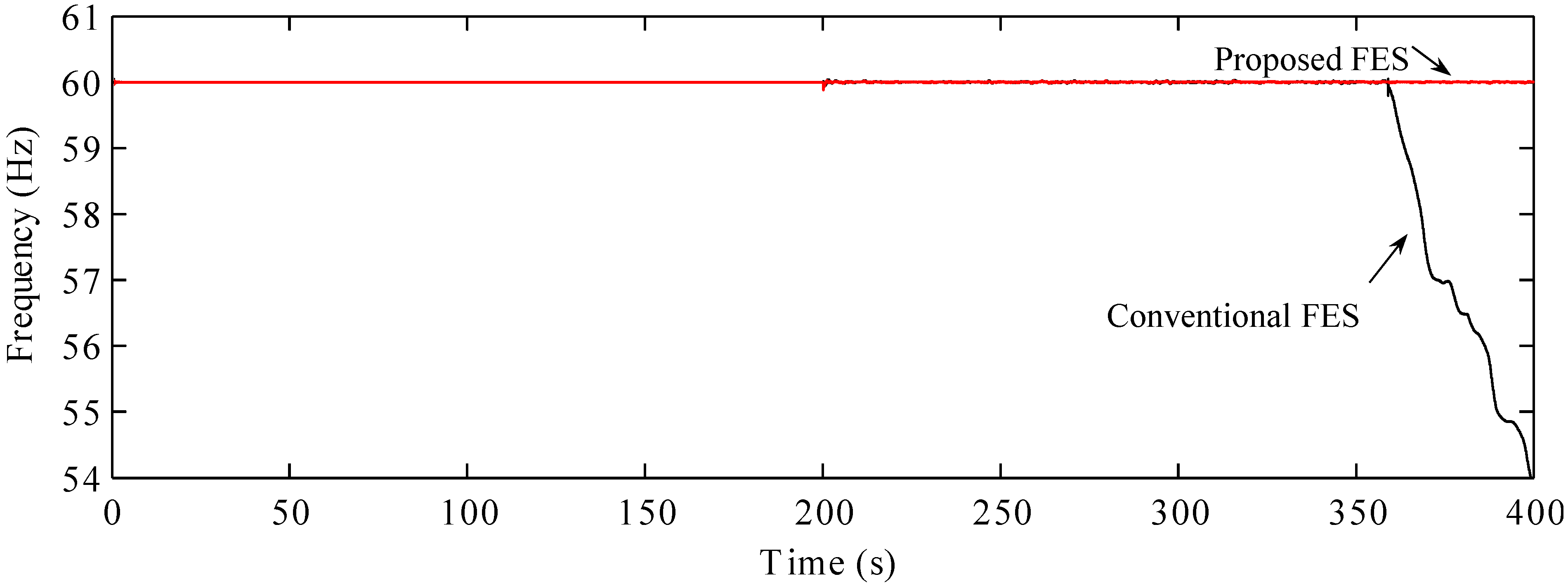
Figure 15 indicate clearly that the proposed FES system exhibited good performance in the islanded mode. In spite of the lower energy rating of this FES system, it could control the frequency of the microgrid in a stable manner. However, in case of the conventional FES system, the frequency could be controlled stably only until the wind speed dropped to the lowest level. A loss of control of the FES system causes a fall in the frequency.
Figure 15.
Frequency of the microgrid.
Figure 15.
Frequency of the microgrid.
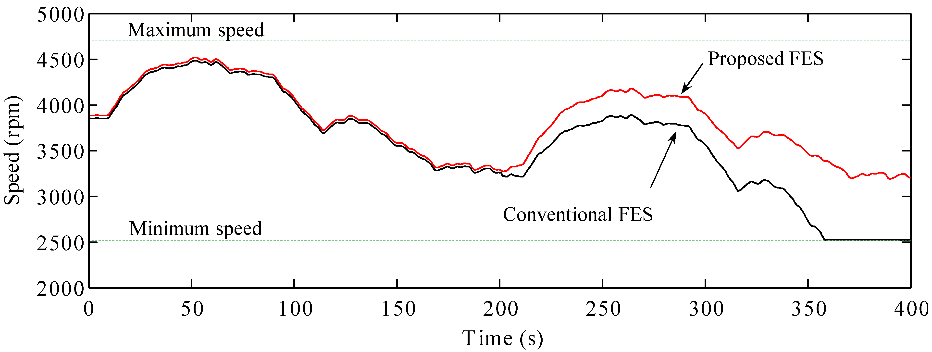
As shown in
Figure 16, the speed of the conventional FES system reduces to the lowest level, leading to the system becoming uncontrollable. The conventional FES system could not control the output power to compensate for the drop in the wind power. Consequently, the power imbalance caused by the loss of one of the power supplies led to the collapse of the microgrid operations.
Figure 16.
Speed of the FES systems.
Figure 16.
Speed of the FES systems.
6. Conclusions
In this paper, we compared the performances of a conventional FES system and a newly proposed one, which had a battery, when used with a microgrid. The addition of an FES system in the microgrid can improve the power quality features, including the frequency and voltage. The fluctuations in the wind power, which have an effect on the frequency of the microgrid, can be reduced by charging or discharging the FES system, as required. In order to control the frequency of the microgrid in a stable manner, very large FES systems are usually required. However, in this paper, we demonstrated that the microgrid power frequency can be controlled stably by using a small FES system such as the one proposed. The coordination of the MSC and GSC control systems in the proposed FES system allows for the rating of the FES system to be lowered. The results of simulations showed that the proposed FES system exhibited better performance than did the conventional FES system.
In the proposed FES system, we assumed an ideal battery whose state of charge was not known. However, it is necessary to take into account the characteristics of the battery in the simulations. Moreover, the control system of the proposed FES system can be integrated into hardware-in-the loop simulations.


