
Power Quality in DC Power Distribution Systems and Microgrids

Abstract
:1. Introduction
2. Sample DC Architectures
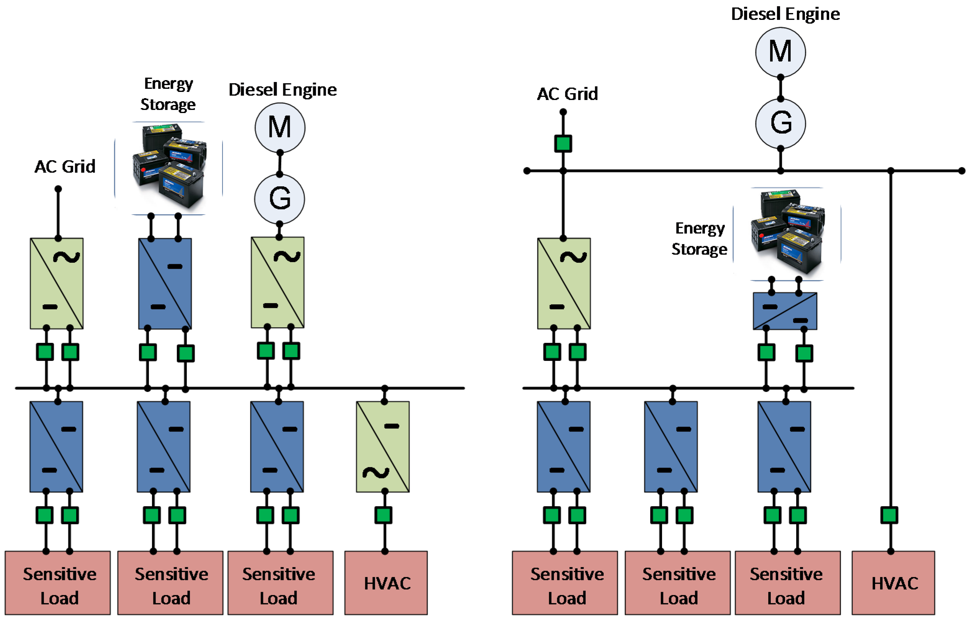
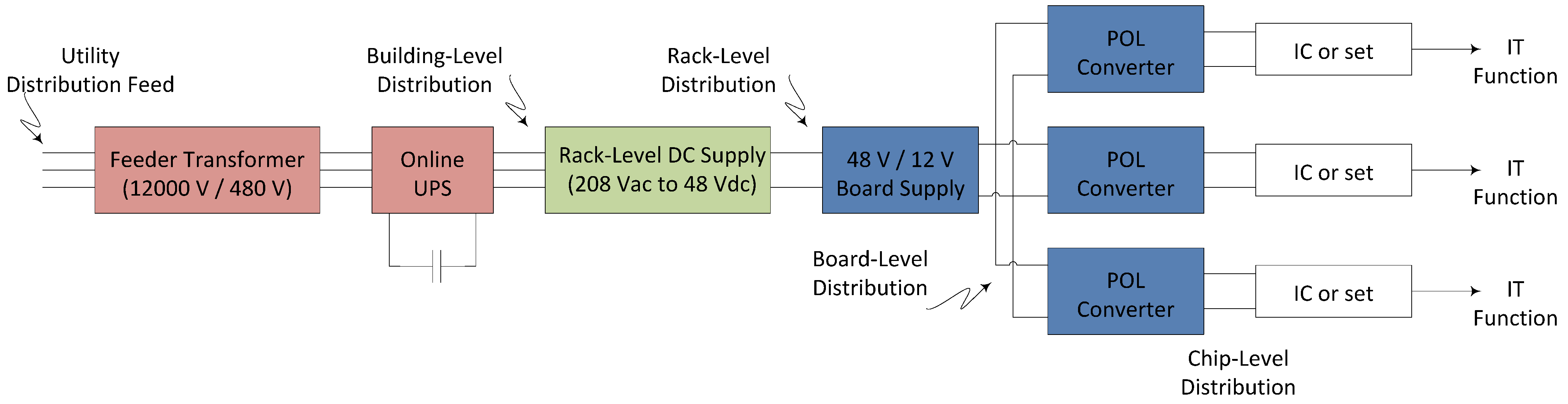
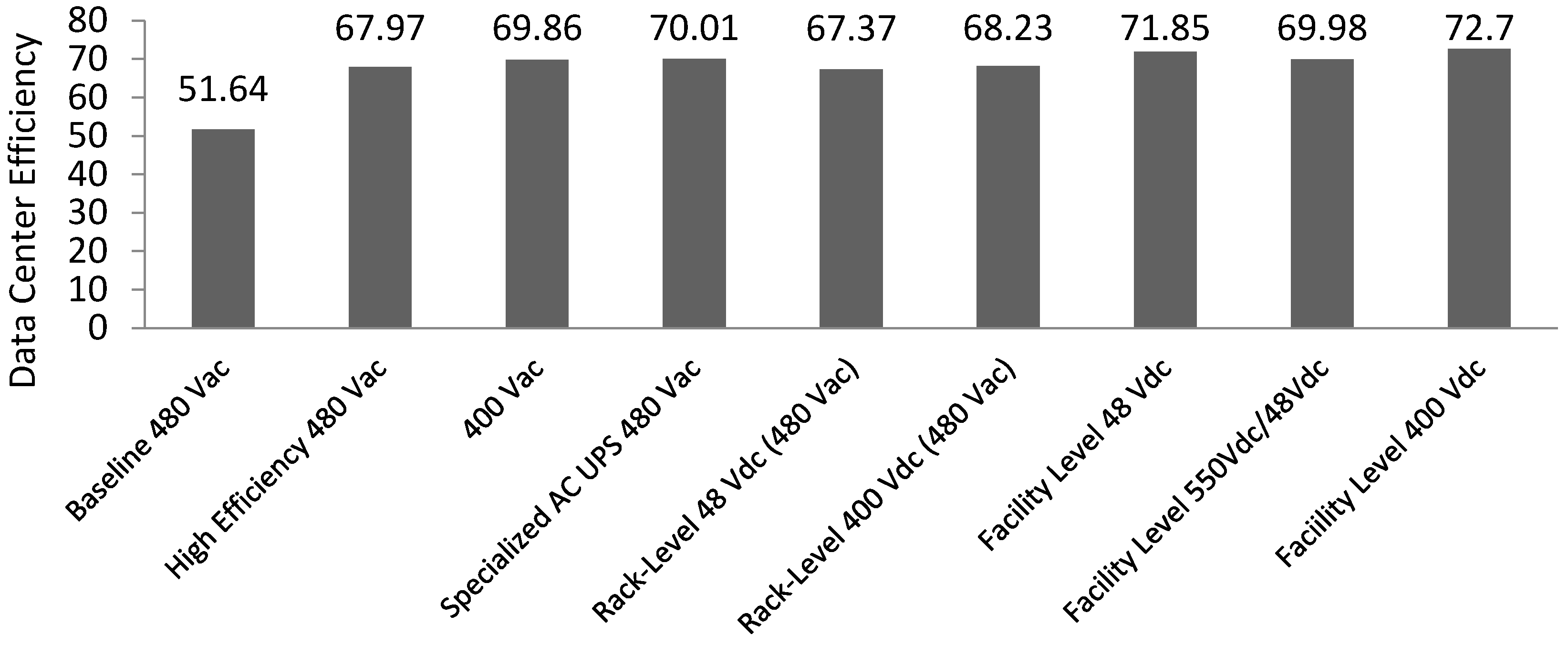
2.1. Data Center Challenges and Approaches towards Improved System Efficiency
2.1.1. State of the Art Data Center Architecture Design for Improved Efficiency


2.1.2. Worldwide DC Data Center Installations and the Need for Standardization
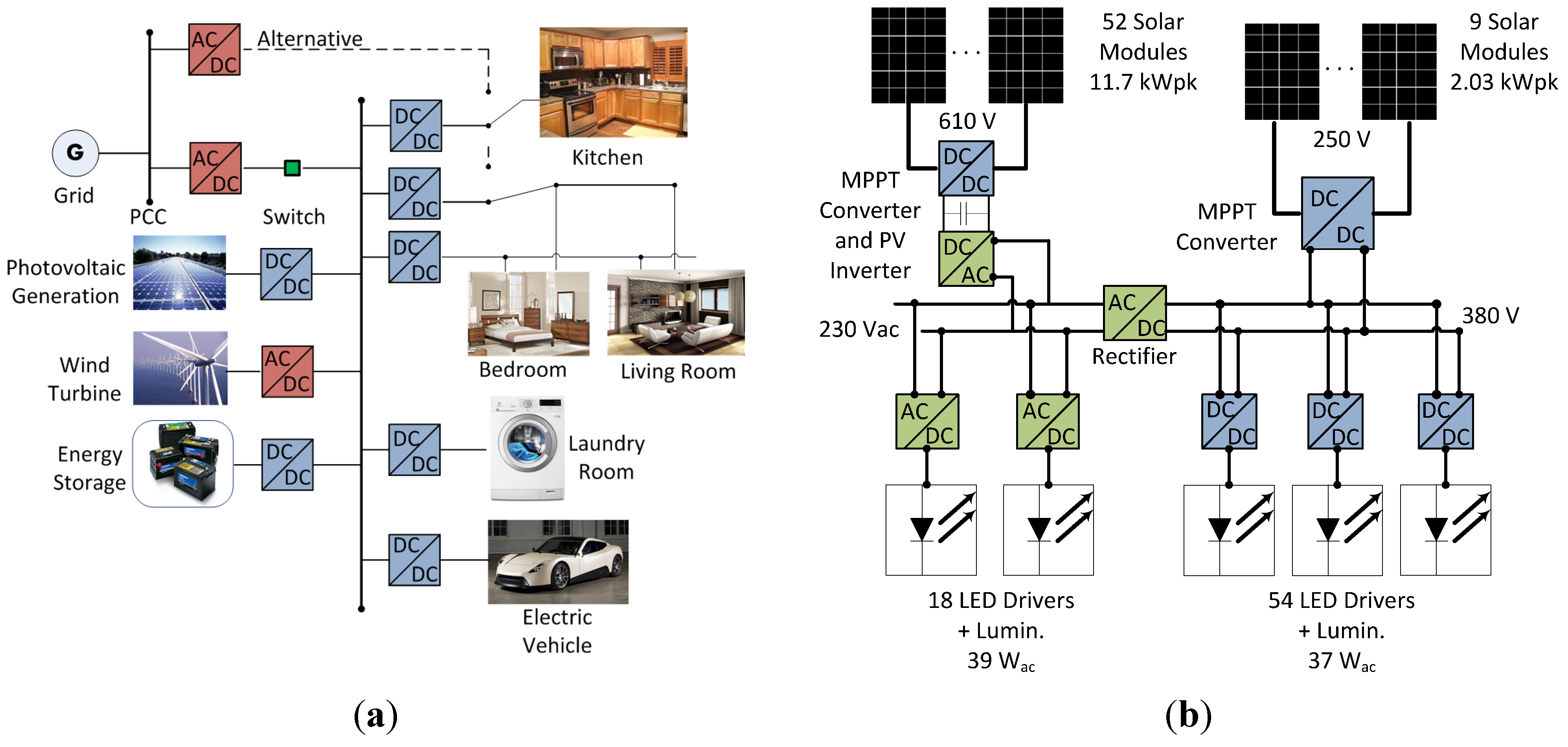
2.2. The Role of DC Microgrids within Commercial Facilities and Residential Homes
2.2.1. Voltage Selection for Home Appliances and Lighting Systems within DC Homes

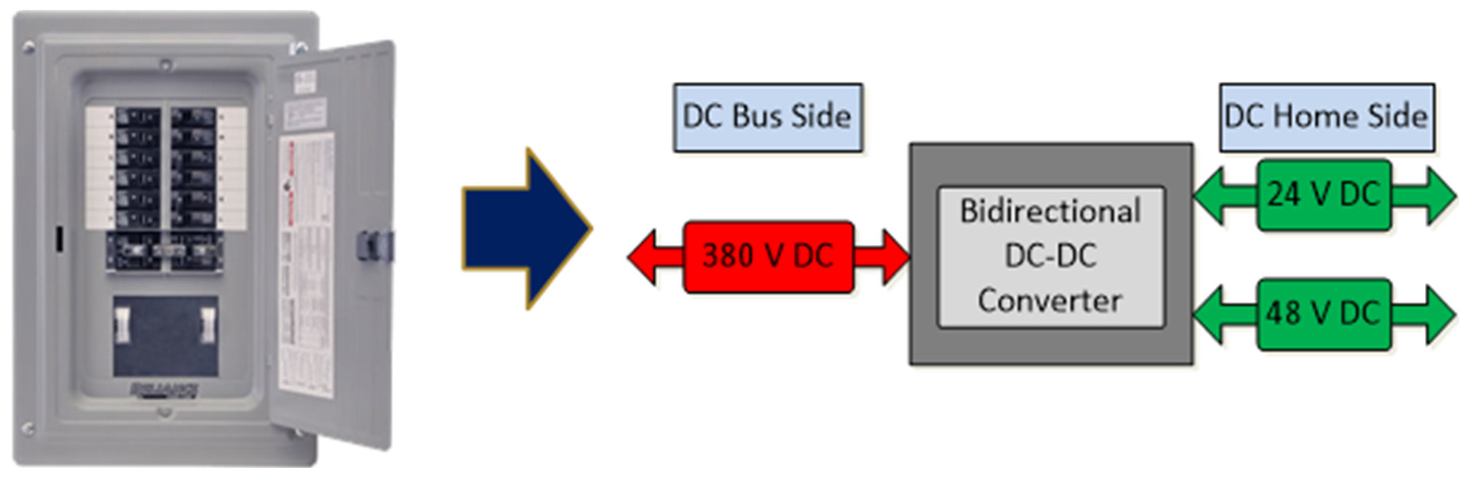
2.2.2. Power Electronic Systems and their Potential Role in Building-Side DC Circuit Breaker Panels
- Achieve bidirectional operation to allow for both traditional power flow from the grid to the home as well as on-site (home-side) renewable generation and energy storage to flow back into the microgrid.
- Provide dynamic protection between the grid and the home from transient electrical phenomenon such as lightning strikes or equipment surges. Currently an isolation stage is mandatory in the United States when interfacing with a power grid with converters as indicated in the National Electric Code so there must be either a low frequency transformer at the input of the PCC between the grid and the microgrid or a high frequency transformer in the converter itself.
- Have the capability to perform as a single-input, multiple-output device with a single 380 V connection to the microgrid DC Bus and two building-side voltages of 24 V [37] and 48 V. A circuit topology to perform these transformations is shown in [43]. These voltage transformations should be accomplished with minimized number and size of magnetic components. For example, new converter topologies have been proposed in the literature using higher frequency switching to reduce transformer size [44].
2.3. DC in Telecommunications Power Systems
2.4. Transmission Level DC Grid Applications
3. AC Power Quality
3.1. Harmonics
3.2. Disturbances
4. Power Quality in DC Distribution Systems and Microgrids
4.1. Harmonic Currents
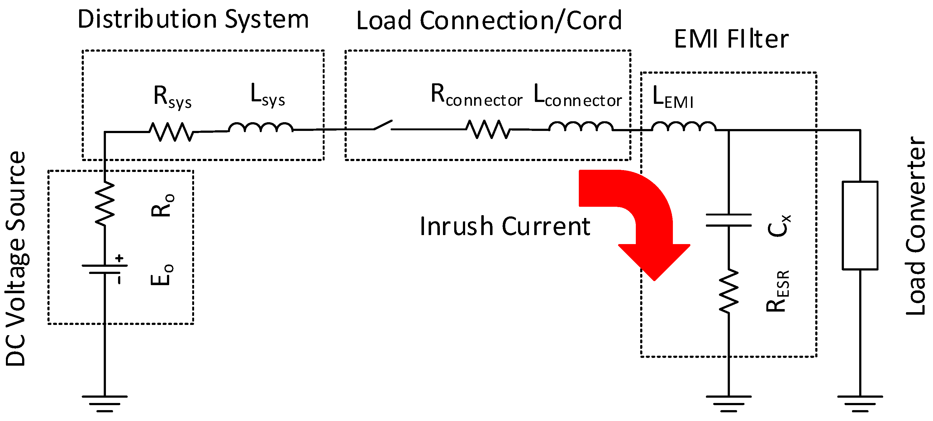
4.2. Inrush Current
4.3. Fault Current
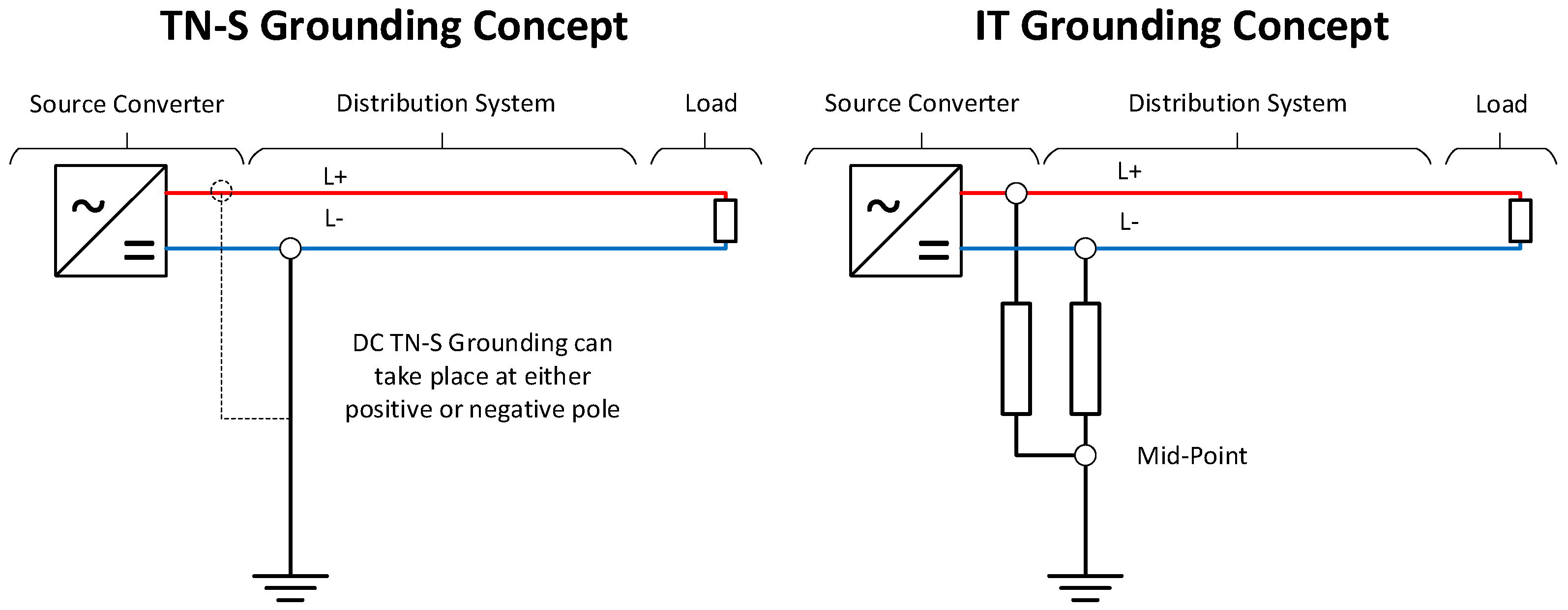
4.4. Grounding

5. Conclusions
Acknowledgments
Author Contributions
Conflicts of Interest
References
- Electric Power Research Institute (EPRI). DC Power Production, Delivery and Utilization; EPRI: Palo Alto, CA, USA, 2006. [Google Scholar]
- Szpek, M.; Sonnenberg, B.J.; Lisy, S.M. 400VDC distribution architectures for central offices and data centers. In Proceedings of the 2014 IEEE 36th International Telecommunications Energy Conference (INTELEC), Vancouver, BC, Canada, 28 September–2 October 2014; pp. 1–6.
- Noritake, M.; Yuasa, K.; Takeda, T.; Hoshi, H.; Hirose, K. Demonstrative research on DC microgrids for office buildings. In Proceedings of the 2014 IEEE 36th International Telecommunications Energy Conference (INTELEC), Vancouver, BC, Canada, 28 September–2 October 2014; pp. 1–5.
- Zhang, W.; Lee, F.C.; Huang, P.-Y. Energy management system control and experiment for future home. In Proceedings of the 2014 IEEE Energy Conversion Congress and Exposition (ECCE), Pittsburgh, PA, USA, 14–18 September 2014; pp. 3317–3324.
- Engelen, K.; Shun, E.L.; Vermeyen, P.; Pardon, I.; D’hulst, R.; Driesen, J.; Belmans, R. The feasibility of small-scale residential DC distribution systems. In Proceedings of the IECON 2006—32nd Annual Conference on IEEE Industrial Electronics, Paris, France, 6–10 November 2006; pp. 2618–2623.
- Ryu, M.-H.; Kim, H.-S.; Kim, J.-H.; Baek, J.-W.; Jung, J.-H. Test bed implementation of 380V DC distribution system using isolated bidirectional power converters. In Proceedings of the 2013 IEEE Energy Conversion Congress and Exposition, Denver, CO, USA, 15–19 September 2013; pp. 2948–2954.
- Kwasinski, A.; Kwasinski, A. Operational aspects and power architecture design for a microgrid to increase the use of renewable energy in wireless communication networks. In Proceedings of the 2014 International Power Electronics Conference (IPEC-Hiroshima 2014—ECCE ASIA), Hiroshima, Japan, 18–21 May 2014; pp. 2649–2655.
- Kwasinski, A.; Kwasinski, A. Role of energy storage in a microgrid for increased use of photovoltaic systems in wireless communication networks. In Proceedings of the 2014 IEEE 36th International Telecommunications Energy Conference (INTELEC), Vancouver, BC, Canada, 28 September–2 October 2014; pp. 1–8.
- Electric Power Research Institute (EPRI). DPQ Executive Summary; EPRI: Palo Alto, CA, USA, 2003. [Google Scholar]
- The Institute of Electrical and Electronics Engineers. Recommended Practices and Requirements for Harmonic Control in Electrical Power Systems; IEEE: Piscataway, NJ, USA, 1993; pp. 1–112. [Google Scholar]
- Prousalidis, J.; Styvaktakis, E.; Kanellos, F.; Perros, S.; Sofras, E. Electric power supply quality in ship systems: An overview. Int. J. Ocean Syst. Manag. 2008, 1, 68–83. [Google Scholar] [CrossRef]
- West, E.G. Analysis of Harmonic Distortion in an Integrated Power System for Naval Applications; Massachusetts Institute of Technology: Cambridge, MA, USA, 2005. [Google Scholar]
- Ericsen, T. Engineering “total electric ship”. In Proceedings of the 2007 IEEE Petroleum and Chemical Industry Technical Conference, Calgary, AB, Canada, 17–19 September 2007; pp. 1–6.
- Moir, I.; Seabridge, A. Aircraft Systems: Mechanical, Electrical and Avionics Subsystems Integration; John Wiley & Sons: Hoboken, NJ, USA, 2011. [Google Scholar]
- Emadi, A.; Rajashekara, K. Power electronics and motor drives in electric, hybrid electric, and plug-in hybrid electric vehicles. IEEE Trans. Ind. Electron. 2008, 55, 2237–2245. [Google Scholar] [CrossRef]
- Lee, Y.H.; Nasiri, A. Analysis and modeling of conductive EMI noise of power electronics converters in electric and hybrid electric vehicles. In Proceedings of the 2008 Twenty-Third Annual IEEE Applied Power Electronics Conference and Exposition, Austin, TX, USA, 24–28 February 2008; pp. 1952–1957.
- Uriarte, F.M.; Hebner, R.E.; Kwasinski, A.; Gattozzi, A.L.; Estes, H.B.; Anwar, A.; Cairoli, P.; Dougal, R.; Dougal, A.; Feng, X.; et al. Technical cross-fertilization between terrestrial microgrids and ship power systems. In Proceedings of the ESRDC 10th Anniversary Meeting, Austin, TX, USA, 4–6 June 2012.
- Masanet, E.R.; Brown, R.E.; Shehabi, A.; Koomey, J.G.; Nordman, B. Estimating the energy use and efficiency potential of U.S. data centers. Proc. IEEE 2011, 99, 1440–1453. [Google Scholar] [CrossRef]
- Candan, E.; Shenoy, P.S.; Pilawa-Podgurski, R.C.N. A series-stacked power delivery architecture with isolated differential power conversion for data centers. In Proceedings of the 2014 IEEE 36th International Telecommunications Energy Conference (INTELEC), Vancouver, BC, Canada, 28 September–2 October 2014; pp. 1–8.
- Krein, P.T. A discussion of data center power challenges across the system. In Proceedings of the 2010 International Conference on Energy Aware Computing, Cairo, Egypt, 16–18 December 2010; pp. 1–3.
- Kwasinski, A. Advanced power electronics enabled distribution architectures: Design, operation, and control. In Proceedings of the 8th International Conference on Power Electronics—ECCE Asia, Jeju, Korea, 30 May–3 June 2011; pp. 1484–1491.
- Kwasinski, A.; Onwuchekwa, C.N. Dynamic behavior and stabilization of DC microgrids with instantaneous constant-power loads. IEEE Trans. Power Electron. 2011, 26, 822–834. [Google Scholar] [CrossRef]
- Salomonsson, D.; Soder, L.; Sannino, A. An adaptive control system for a DC microgrid for data centers. IEEE Trans. Ind. Appl. 2008, 44, 1910–1917. [Google Scholar] [CrossRef]
- Kwasinski, A. Analysis of electric power architectures to improve availability and efficiency of air conditioning systems. In Proceedings of the INTELEC 2008—2008 IEEE 30th International Telecommunications Energy Conference, San Diego, CA, USA, 14–18 September 2008; pp. 1–8.
- Zhang, W.; Guo, B.; Xu, F.; Cui, Y.; Long, Y.; Wang, F.; Tolbert, L.M.; Blalock, B.J.; Costinett, D.J. Wide bandgap power devices based high efficiency power converters for data center application. In Proceedings of the 2014 IEEE Workshop on Wide Bandgap Power Devices and Applications, Knoxville, TN, USA, 13–15 October 2014; pp. 121–126.
- Shenoy, P.S.; Krein, P.T. Differential power processing for DC systems. IEEE Trans. Power Electron. 2013, 28, 1795–1806. [Google Scholar] [CrossRef]
- Pratt, A.; Kumar, P.; Aldridge, T.V. Evaluation of 400V DC distribution in telco and data centers to improve energy efficiency. In Proceedings of the INTELEC 07—29th International Telecommunications Energy Conference, Rome, Italy, 30 September–4 October 2007; pp. 32–39.
- Allen, W.; Natale, S.V. Achieving ultra-high system availability in a battery-less-48VDC power plant. In Proceedings of the 24th Annual International Telecommunications Energy Conference, Montréal, QC, Canada, 29 September–3 October 2002; pp. 287–294.
- Inamori, J.; Hoshi, H.; Tanaka, T.; Babasaki, T.; Hirose, K. 380-VDC power distribution system for 4-MW-scale cloud facility. In Proceedings of the 2014 IEEE 36th International Telecommunications Energy Conference (INTELEC), Vancouver, BC, Canada, 28 September–2 October 2014; pp. 1–8.
- Hirose, K. Consideration of voltage range of a 380 VDC distribution system for international standardization. In Proceedings of the 2013 35th International Telecommunications Energy Conference ‘Smart Power and Efficiency’ (INTELEC), Hamburg, Germany, 13–17 October 2013; pp. 1–6.
- AlLee, G.; Tschudi, W. Edison redux: 380 Vdc brings reliability and efficiency to sustainable data centers. IEEE Power Energy Mag. 2012, 10, 50–59. [Google Scholar] [CrossRef]
- Marnay, C. On voltage standards for DC home microgrids energized by distributed sources. In Proceedings of the 7th International Power Electronics and Motion Control Conference, Harbin, China, 2–5 June 2012; Volume 3, pp. 2282–2286.
- Patterson, B.T. DC, come home: DC microgrids and the birth of the “Enernet”. IEEE Power Energy Mag. 2012, 10, 60–69. [Google Scholar] [CrossRef]
- Office of Electricity Delivery and Energy Reliability. Power Electronics Research and Development Program Plan; Office of Electricity Delivery and Energy Reliability: Washington, DC, USA, 2011; p. 21. [Google Scholar]
- Lucia, O.; Cvetkovic, I.; Sarnago, H.; Boroyevich, D.; Mattavelli, P.; Lee, F.C. Design of home appliances for a DC-based nanogrid system: An induction range study case. IEEE J. Emerg. Sel. Top. Power Electron. 2013, 1, 315–326. [Google Scholar] [CrossRef]
- Thomas, B.A. Edison revisited: Impact of DC distribution on the cost of LED lighting and distributed generation. In Proceedings of the 2010 Twenty-Fifth Annual IEEE Applied Power Electronics Conference and Exposition (APEC), Palm Springs, CA, USA, 21–25 February 2010; pp. 588–593.
- Wunder, B.; Ott, L.; Szpek, M.; Boeke, U.; Weis, R. Energy efficient DC-grids for commercial buildings. In Proceedings of the 2014 IEEE 36th International Telecommunications Energy Conference (INTELEC), Vancouver, BC, Canada, 28 September–2 October 2014; pp. 1–8.
- Thomas, B.A.; Azevedo, I.L.; Morgan, G. Edison revisited: Should we use DC circuits for lighting in commercial buildings? Energy Policy 2012, 45, 399–411. [Google Scholar] [CrossRef]
- Starke, M.; Tolbert, L.M.; Ozpineci, B. AC vs. DC distribution: A loss comparison. In Proceedings of the 2008 IEEE/PES Transmission and Distribution Conference and Exposition, Chicago, IL, USA, 21–24 April 2008; pp. 1–7.
- Reed, G.F.; Grainger, B.M.; Sparacino, A.R. Ship to grid: Medium-voltage DC concepts in theory and practice. IEEE Power Energy Mag. 2012, 10, 70–79. [Google Scholar] [CrossRef]
- Guerrero, J.M.; Vasquez, J.C.; Matas, J.; de Vicuna, L.G.; Castilla, M. Hierarchical control of droop-controlled AC and DC microgrids—A general approach toward standardization. IEEE Trans. Ind. Electron. 2011, 58, 158–172. [Google Scholar] [CrossRef]
- Kwasinski, A. Identification of feasible topologies for multiple-input DC-DC converters. IEEE Trans. Power Electron. 2009, 24, 856–861. [Google Scholar] [CrossRef]
- Behjati, H.; Davoudi, A. A multiple-input multiple-output DC-DC converter. IEEE Trans. Ind. Appl. 2013, 49, 1464–1479. [Google Scholar] [CrossRef]
- Madhusoodhanan, S.; Tripathi, A.; Patel, D.; Mainali, K.; Bhattacharya, S. Stability analysis of the high voltage DC link between the FEC and DC-DC stage of a transformer-less intelligent power substation. In Proceedings of the 2014 IEEE Energy Conversion Congress and Exposition (ECCE), Pittsburgh, PA, USA, 14–18 September 2014; pp. 3702–3709.
- De Doncker, R.W.A.A.; Divan, D.M.; Kheraluwala, M.H. A three-phase soft-switched high-power-density DC/DC converter for high-power applications. IEEE Trans. Ind. Appl. 1991, 27, 63–73. [Google Scholar] [CrossRef]
- Kwasinski, A. Telecommunications outside plant power infrastructure: Past performance and technological alternatives for improved resilience to hurricanes. In Proceedings of the INTELEC 2009—31st International Telecommunications Energy Conference, Incheon, Korea, 18–22 October 2009; pp. 1–6.
- Kwasinski, A.; Kwasinski, A. Increasing sustainability and resiliency of cellular networks infrastructure by harvesting renewable energy. IEEE Commun. Mag. 2015, 53, 110–116. [Google Scholar] [CrossRef]
- Meyer, C.; Hoing, M.; Peterson, A.; de Doncker, R.W. Control and design of DC grids for offshore wind farms. IEEE Trans. Ind. Appl. 2007, 43, 1475–1482. [Google Scholar] [CrossRef]
- Chen, W.; Huang, A.Q.; Li, C.; Wang, G.; Gu, W. Analysis and comparison of medium voltage high power DC/DC converters for offshore wind energy systems. IEEE Trans. Power Electron. 2014, 28, 2014–2023. [Google Scholar] [CrossRef]
- The Institute of Electrical and Electronics Engineers. IEEE Guide for Identifying and Improving Voltage Quality in Power Systems; IEEE: Piscataway, NJ, USA, 2011; pp. 1–70. [Google Scholar]
- Electric Power Research Institute (EPRI). DPQ Report: Surveying Power Quality Levels on U.S. Distribution Systems; EPRI: Palo Alto, CA, USA, 2003. [Google Scholar]
- Guerrero, J.M.; Loh, P.C.; Lee, T.-L.; Chandorkar, M. Advanced control architectures for intelligent microgrids—Part II: Power quality, energy storage, and AC/DC microgrids. IEEE Trans. Ind. Electron. 2013, 60, 1263–1270. [Google Scholar] [CrossRef]
- Siemens AG. Microgrids; Siemens AG: Berlin, Germany, 2011. [Google Scholar]
- Cividino, L. Power factor, harmonic distortion; causes, effects and considerations. In Proceedings of the Fourteenth International Telecommunications Energy Conference—INTELEC’92, Washington, DC, USA, 4–8 October 1992; pp. 506–513.
- Grady, W.M.; Gilleskie, R.J. Harmonics and how they relate to power factor. In Proceedings of the EPRI Power Quality Issues & Opportunities Conference (PQA’93), San Diego, CA, USA, 16–19 November 1993; pp. 1–8.
- Li, Y.W.; He, J. Distribution system harmonic compensation methods: An overview of DG-interfacing inverters. IEEE Ind. Electron. Mag. 2014, 8, 18–31. [Google Scholar] [CrossRef]
- Electric Power Research Institute (EPRI). Distribution System Power Quality Assessment Phase II: Voltage Sag and Interruption Analysis; EPRI: Palo Alto, CA, USA, 2003; Volume 3. [Google Scholar]
- Zhang, R.; Lee, F.C.; Boroyevich, D.; Liu, C.; Chen, L. AC load conditioner and DC bus conditioner for a DC distribution power system. In 2000 IEEE 31st Annual Power Electronics Specialists Conference. Conference Proceedings (Cat. No.00CH37018); IEEE: Piscataway, NJ, USA, 2000; Volume 1, pp. 107–112. [Google Scholar]
- Xu, Z.; Huang, Y.; Li, X.; Wang, F. DC harmonic current calculation for HVDC systems based on the classical transmission line model. In Proceedings of the 2010 International Conference on Power System Technology, Hangzhou, China, 24–28 October 2010; pp. 1–5.
- Graham, A.D. The importance of a DC side harmonic study for a DC distribution system. In Proceedings of the 6th IET International Conference on Power Electronics, Machines and Drives (PEMD 2012), Bristol, UK, 27–29 March 2012; pp. 1–5.
- Zhang, H.; Wheeler, N.; Grant, D. Switching harmonics in the DC link current in a PWM AC-DC-AC converter. In Proceedings of the IAS ’95. Conference Record of the 1995 IEEE Industry Applications Conference Thirtieth IAS Annual Meeting, Orlando, FL, USA, 8–12 October 1995; Volume 3, pp. 2649–2655.
- Bierhoff, M.H.; Fuchs, F.W. DC-link harmonics of three-phase voltage-source converters influenced by the pulsewidth-modulation strategy—An analysis. IEEE Trans. Ind. Electron. 2008, 55, 2085–2092. [Google Scholar] [CrossRef]
- McGrath, B.P.; Holmes, D.G. A general analytical method for calculating inverter DC-link current harmonics. IEEE Trans. Ind. Appl. 2009, 45, 1851–1859. [Google Scholar] [CrossRef]
- Browne, T.J.; Browne, N.R. Power quality considerations for utilities supplying residential DC installations. In Proceedings of the 2008 13th International Conference on Harmonics and Quality of Power, Wollongong, Australia, 28 September–1 October 2008; pp. 1–5.
- Blooming, T.M.; Carnovale, D.J. Application of IEEE STD 519–1992 Harmonic Limits. In Proceedings of the Conference Record of Annual on Pulp and Paper Industry Technical Conference, 2006, Appleton, WI, USA, 18–23 June 2006; pp. 1–9.
- Hoshi, H.; Tanaka, T.; Noritake, M.; Ushirokawa, T.; Hirose, K.; Mino, M. Consideration of inrush current on DC distribution system. In Proceedings of the 2012 IEEE 34th International Telecommunications Energy Conference (INTELEC), Scottsdale, AZ, USA, 30 September–4 October 2012; pp. 1–4.
- Asakimori, K.; Murai, K.; Tanaka, T.; Babasaki, T. Effect of inrush current flowing into EMI filter on the operation of ICT equipment in HVDC system. In Proceedings of the 2014 IEEE 36th International Telecommunications Energy Conference (INTELEC), Vancouver, BC, Canada, 28 September–2 October 2014; pp. 1–5.
- Davies, B. Analysis of inrush currents for DC powered IT equipment. In Proceedings of the 2011 IEEE 33rd International Telecommunications Energy Conference (INTELEC), Amsterdam, The Netherlands, 9–13 October 2011; pp. 1–4.
- Iino, T.; Hirose, K.; Noritake, M.; Nakamura, A.; Kiryu, K.; Sekikawa, J. Characteristics of 400 V dc plug and socket-outlet for DC distribution systems. In Proceedings of the 2012 International Conference on Renewable Energy Research and Applications (ICRERA), Nagasaki, Japan, 11–14 November 2012; pp. 1–6.
- Aoki, T.; Yamasaki, M.; Takeda, T.; Tanaka, T.; Harada, H.; Nakamura, K. Guidelines for power-supply systems for datacom equipment in NTT. In Proceedings of the 24th Annual International Telecommunications Energy Conference, Montréal, QC, Canada, 29 September–3 October 2002; pp. 134–139.
- Lazaroiu, G.C.; Tironi, E.; Popescu, M.O.; Ghita, O.; Dumbrava, V. Transient analysis of DG interfaced low voltage dc system. In Proceedings of 14th International Conference on Harmonics and Quality of Power—ICHQP 2010, Bergamo, Italy, 26–29 September 2010; pp. 1–6.
- Giancaterino, J.A. DC-DC converter plants and their ability to clear distribution fuses. In Proceedings of the 16th International Telecommunications Energy Conference, 1994, INTELEC’94, Vancouver, BC, Canada, 30 October–3 November 1994; pp. 315–320.
- Estes, H.B.; Kwasinski, A.; Hebner, R.E.; Uriarte, F.M.; Gattozzi, A.L. Open series fault comparison in AC & DC micro-grid architectures. In Proceedings of the 2011 IEEE 33rd International Telecommunications Energy Conference (INTELEC), Amsterdam, The Netherlands, 9–13 October 2011; pp. 1–6.
- Uriarte, F.M.; Gattozzi, A.L.; Herbst, J.D.; Estes, H.B.; Hotz, T.J.; Kwasinski, A.; Hebner, R.E. A DC arc model for series faults in low voltage microgrids. IEEE Trans. Smart Grid 2012, 3, 2063–2070. [Google Scholar] [CrossRef]
- Salomonsson, D.; Soder, L.; Sannino, A. Protection of low-voltage DC microgrids. IEEE Trans. Power Deliv. 2009, 24, 1045–1053. [Google Scholar] [CrossRef]
- Cuzner, R.M.; Venkataramanan, G. The Status of DC Micro-Grid Protection. In Proceedings of the 2008 IEEE Industry Applications Society Annual Meeting, Edmonton, AB, Canada, 5–9 October 2008; pp. 1–8.
- European Telecommunications Standards Institute (ETSI). ETSI EN 301 605—Environmental Engineering (EE); Earthing and Bonding of 400 VDC Data and Telecom (ICT) Equipment; ETSI: Nice, France, 2011; Volume 1, pp. 1–85. [Google Scholar]
© 2015 by the authors; licensee MDPI, Basel, Switzerland. This article is an open access article distributed under the terms and conditions of the Creative Commons Attribution license (http://creativecommons.org/licenses/by/4.0/).
Share and Cite
Whaite, S.; Grainger, B.; Kwasinski, A. Power Quality in DC Power Distribution Systems and Microgrids. Energies 2015, 8, 4378-4399. https://doi.org/10.3390/en8054378
Whaite S, Grainger B, Kwasinski A. Power Quality in DC Power Distribution Systems and Microgrids. Energies. 2015; 8(5):4378-4399. https://doi.org/10.3390/en8054378
Chicago/Turabian StyleWhaite, Stephen, Brandon Grainger, and Alexis Kwasinski. 2015. "Power Quality in DC Power Distribution Systems and Microgrids" Energies 8, no. 5: 4378-4399. https://doi.org/10.3390/en8054378