3.1. Numerical Study on Electric Field Distributions
In the experiment, the spatial electric field distributions at various input voltages are simulated using ANSYS 13.0. For simplicity,
Figure 3 only shows the electric field distributions in the vertical cross section along the bomb centerline at the input voltage of −12 kV.
It can be seen in
Figure 3 that the electric fields produced by the high-voltage electrodes are typically non-uniform but their distributions are all symmetrical. The electric field strengths in the horizontal direction are more intense than that in the vertical direction. Meanwhile, the direction of the electric field line mostly points horizontally to the high-voltage electrodes from the vertical bomb centerline and the bomb circumference.
Figure 3.
Electric field distributions at input voltage of −12 kV.
Figure 3.
Electric field distributions at input voltage of −12 kV.
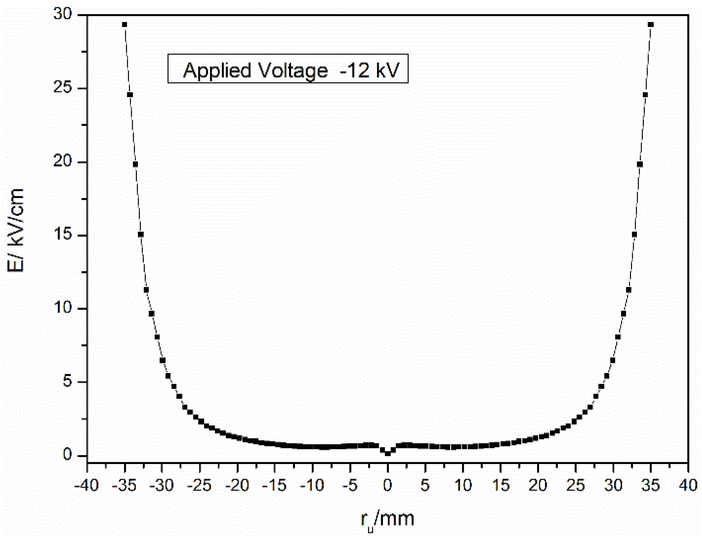
Figure 4 shows the value of electric field strength along the bomb horizontal centerline between the high-voltage electrodes at the input voltage of −12 kV. The electric field strength of each position can be obtained from
Figure 4, and the mean value of the electric field strength is defined as the ratio of the sum of the electric field strength of each position to the number of the electric field strength position. It can be seen that the value of the electric field strength almost monotonous increases from 0.14 × 10
5 V/m (located in the ignition electrodes) to 2.95 × 10
6 V/m (located in the high-voltage electrodes). While the electric fields in the region within 27 mm away from the center are relatively uniform, its mean value being about 1.45 × 10
5 V/m, However, in the region close to the needle tip, the electric field intensity increases significantly, reaching about 2.95 × 10
6 V/m from 2.7 × 10
5 V/m in an interval distance of about 8 mm. The changing trends of the electric field strength at the input voltage of −5 kV and −10 kV are in consistent with that at −12 kV due to the electric field strength proportional to the applied voltages.
Figure 4.
The electric field strength versus the horizontal distance for the case at −12 kV.
Figure 4.
The electric field strength versus the horizontal distance for the case at −12 kV.
3.2. Influence of the Electric Field on the Flame Shape Modification
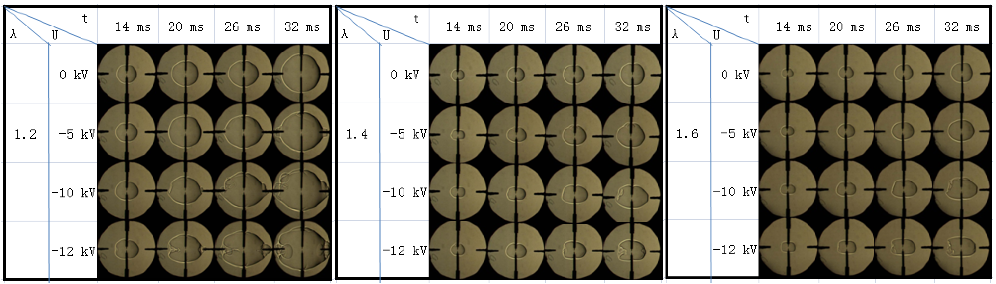
Figure 5 shows images of flame propagation processes at λ = 1.2, 1.4 and 1.6 under the various applied electric fields. The input voltages and the elapsed times after ignition are correspondingly tabulated beside the relevant flame images. At an input voltage of 0 kV,
i.e., in the absence of electric fields, the flame front at any excess air ratio is almost spherical shape and propagates evenly in both horizontal and vertical directions. It also can be seen that the flame propagates relatively slower when the mixture becomes leaner. When the input voltage is −5 kV, the flame front in the horizontal direction is slightly stretched, whereas the flame front almost remains spherical in shape, and the flame surface almost keeps smooth in the process of the flame development. While, when the applied voltage increases to −10 kV, or −12 kV, the horizontal flame front is lengthened markedly and propagates evenly in both the rightward and leftward direction, whereas the vertical flame propagation changes little. In the case of the three excess air ratios, there is an apparent discrepancy between the changes in the flame shape. For λ = 1.2, the flame front shape changes little, and almost retains its previous spherical flame front, while for λ = 1.4 and 1.6, due to the flame front in the horizontal direction is prolonged remarkably, the flame front takes on a prolate sphere shape.
Figure 5.
Images of flame propagation process at excess air ratio of λ = 1.2, 1.4, and 1.6.
Figure 5.
Images of flame propagation process at excess air ratio of λ = 1.2, 1.4, and 1.6.
The lengthening of the flame front in the horizontal direction under the electric field is primarily ascribed to the ionic wind effect,
i.e., a bulk flow movement due to electric-field-induced directional collisions of ions and neutral molecules in flame front [
11,
12]. It is accepted that the positive ions such as H
3O
+, C
2H
4+ and CHO
+ formed in the methane flame contribute more to the ion molecule collision because of their abundance and greater mass compared with electrons [
14]. The ionic wind effect, which increases with electric field intensity and particle number density, generates the momentum transfer of positive ions and the acceleration of neutral molecules with which the ions collide. As a consequence, the ion-neutral collisions within the flame front, the flame propagates more rapidly in the field direction compared to that in the other orientations. As shown in
Figure 3, the applied electric fields are almost horizontally oriented toward the two high-voltage electrodes from the vertical bomb centerline, and the magnitude of the electric field in the horizontal direction is more intense than that in the vertical direction. This indicates that the applied electric field can noticeably accelerate the horizontal flame propagation and stretch the flame front, but has little influence on the vertical flame propagation. Moreover, the electric field enhances the flame propagation from a low input voltage, and the effect gradually increases as the input voltage increases. This results in that the flame shape deforms more significant at high input voltage.
It can be also seen that under the applied electric field, the flame shape modifies more pronounced for the leaner mixture. This can be explained by the fact that the ionic wind effect on the flame development can be relevant to the flame propagation status itself. For leaner mixture, flame propagation would take more time within a certain distance due to its slow flame propagation. This would lengthen the period of the applied electric field influence on the combustion process. According to the theory of ionic wind effect [
22], the amount of accelerated neutral molecules which have collided with the positive ions and gained momentum from them will be increased when the available time is lengthened, and this can markedly enhance the effect of the electric field on flame propagation. In the case of the relatively slow propagation speed without electric field, the increase rate of the flame propagation can be great under the electric field. As a consequence, the stretch of the flame front is relatively larger and the flame shape modification is more significant for the leaner mixture.
3.3. Influence of the Electric Field on Flame Propagation Velocity
As shown in
Figure 5, the flame front propagation can change greatly under the applied electric field. For the three excess air ratios studied here, the flame front propagation in the horizontal direction is remarkably accelerated, while the vertical flame propagation is weakly affected. Therefore, the horizontal flame speed is investigated to elucidate the influence of the applied electric fields on flame propagation. The stretched flame propagation velocity
Sn, reflecting the flame moving speed relative to the motionless combustion wall, is derived from the flame propagation radius
versus time,
. where,
ru is the horizontal flame radius and
t is the elapsed time after spark ignition. In this paper, for the sake of more accurately calculating
Sn,
ru is defined as the mean value of various flame radius from the ignition center to the flame front at the set polar angles of 0°, ±15°, ±165° and 180°, respectively, as shown in
Figure 6. Previous studies showed the ignition energy gave an important influence on the flame at the initial stage of the combustion. While as the flame radius is larger than 5 mm, the influence would disappear [
30]. In addition, in order to avoid the wall and pressure influence (the pressure rise rate is less than 1.0%) in the combustion chamber, the analysis of the flame radius is limited to 25 mm [
30]. The data in this study use those of the flame radius from 5 to 25 mm.
Figure 6.
Data obtained from a flame image. (a) Spherical flame, (b) Stretched flame.
Figure 6.
Data obtained from a flame image. (a) Spherical flame, (b) Stretched flame.
Figure 7 gives the variations of flame radius
versus the time under the electric field. The excess air ratios are 1.2, 1.4 and 1.6, and the input voltages are 0 kV, −5 kV, −10 kV and −12 kV, respectively. For an input voltage of 0 kV, the flame radius increases almost linearly with time and the flame propagates slower as the excess air ratio is increased. Under the applied electric field, the flame radius at a given time is larger than that without electric field, indicating that the input electric field can enhance flame propagation. Additionally, the higher the input voltage, the faster the flame propagates. For the three excess air ratios, the increase in the flame propagation at λ = 1.6 is the largest, and that for λ = 1.4 and 1.2 the less large in return. For example, at the input voltage of −12 kV, when
ru increases to 25 mm, the corresponding time are 12.74, 17.53 and 23.96 ms for λ = 1.2, 1.4 and 1.6,which are advanced by 23.7%, 31.1% and 37.0%, respectively, compared to that when no electric field is applied. These results further reveal that the electric field can significantly stretch the flame front as the input voltage increases, and this phenomenon is the more obvious for leaner mixture.
Figure 7.
Flame radius versus combustion time under various conditions. (a) λ = 1.2, (b) 1.4, and (c) 1.6 with the voltages of 0, −5, −10, −12 kV.
Figure 7.
Flame radius versus combustion time under various conditions. (a) λ = 1.2, (b) 1.4, and (c) 1.6 with the voltages of 0, −5, −10, −12 kV.
Figure 8 gives the relationship between the stretched flame propagation velocity
Sn and the flame radius
ru. In the absence of applied voltage for each excess air ratio, the stretched flame propagation velocity increases slightly with the increase of flame radius, and our experiment results are concordant with that cited in the previous literature [
30,
31]. Under the influence of the electric field,
Sn for any excess air ratio increases rapidly compared with the case without electric field, and the effects are increased with the input voltage increase. The peak values of
Sn are 1.86, 1.34 and 1.06 m/s, occurring at voltage of −12 kV, for λ = 1.2, 1.4 and 1.6, and they are increased by 34%, 56%, 67% compared to the case of no electric field, respectively. Additionally, the influence of the electric field on
Sn increases with the flame propagation. The enhancement of
Sn can be ascribed to the field-induced flame stretch due to the ionic wind effect, whose increase tendency is concordant with the increase of the corresponding flame radius under the same conditions.
Figure 8.
Stretched flame propagation velocity versus flame radius under various conditions. (a) λ = 1.2, (b) 1.4, (c) 1.6 with the voltages of 0, −5, −10, −12 kV.
Figure 8.
Stretched flame propagation velocity versus flame radius under various conditions. (a) λ = 1.2, (b) 1.4, (c) 1.6 with the voltages of 0, −5, −10, −12 kV.
From above the flame shape changes and the increase of the stretched flame propagation velocity, it can be seen that the flame development can be influenced by these so-called stretched effects induced by the electric field. The stretch in flame comprises hydrodynamic stretch and flame stretch. Their detailed definition can be found in Reference [
32]; here we directly adopt the relevant concepts. The hydrodynamic stretch, through the combined effects of the tangential and normal velocity gradient at the flame, displaces the flame surface, distorts the flame geometry, and modifies the volumetric burning rate. The positive hydrodynamic stretch pointes in the upstream direction of the flame (toward the unburned zone), while the negative hydrodynamic stretch pointes in the downstream direction of the flame (toward the burnt zone). The flame stretch can directly affect the normal mass flux entering the reaction zone by the tangential velocity variation in the transport zone. Moreover, through interaction with heat and mass diffusion, the flame stretch can modify the temperature and concentration profiles in the transport zone and consequently the burning intensity. During the flame propagation, the flame stretch and hydrodynamic stretch are strongly coupled in flame, and can affect the flames responses and structure. The present experimental data show that the flame front in the electric field direction is stretched and form the pocket regime convex towards unburned gas. The phenomena indicate that the applied electric field can augment the positive hydrodynamic stretch in flame. In addition, the increase rate of the flame radius propagation at λ = 1.6 is the largest, that for λ = 1.4 the less large and that for λ = 1.2 the smallest. Meanwhile, the increase rate of the corresponding stretched flame propagation velocity also show same change trend. This shows the electric field-induced stretch is enhanced with the increase of input voltage, and the result is relatively greater for leaner mixture.
For the sake of comparison of the effects of the applied electric field on the laminar flame speed as a whole,
Table 1 gives the average flame propagation velocity
Sm at λ = 1.2, 1.4, 1.6 and their increase rate Δ
Sm under different input voltages.
Sm is calculated by
Sm = (
r2 −
r1)/(
t2 −
t1), in which,
r1 = 5 mm,
r2 = 25 mm,
t1 and
t2 is the time that the flame radius increases to
r1 and
r2, respectively. Δ
Sm is defined as follow:
, where
Sm and
Sm0 are the average flame propagation velocity for the case at a certain input voltage and 0 kV, respectively. Without the applied voltage,
Sm gives its maximum value at λ = 1.2, and the value at λ = 1.4 and 1.6 decreases in turn progressively. When the input voltage is applied to the mixtures at any excess air rate,
Sm increases steadily with the increase of the input voltage. Moreover, Δ
Sm for λ = 1.6 is the biggest, while its value becomes less big for λ = 1.4 and 1.2 successively. For example, at the applied voltage of −12 kV,
Sm for λ = 1.2, 1.4, and 1.6 are 1.69, 1.22, and 0.9 m/s, and their corresponding Δ
Sm are 30.0%, 48.8% and 57.9%, respectively. The result indicates the electric field can enhance the flame laminar speed, and the improvement effect is more pronounced when the mixture becomes leaner.
Table 1.
Average flame propagation velocity (m/s) and its increase rate for various excess air ratios.
Table 1.
Average flame propagation velocity (m/s) and its increase rate for various excess air ratios.
| U (kV) | λ = 1.2 | λ = 1.4 | λ = 1.6 |
|---|
| Sm (m/s) | ΔSm (%) | Sm (m/s) | ΔSm (%) | Sm (m/s) | ΔSm (%) |
|---|
| 0 | 1.30 | 0 | 0.82 | 0 | 0.57 | 0 |
| −5 | 1.39 | 6.9 | 0.98 | 19.5 | 0.71 | 24.6 |
| −10 | 1.59 | 22.3 | 1.12 | 36.6 | 0.80 | 40.4 |
| −12 | 1.69 | 30.0 | 1.22 | 48.8 | 0.90 | 57.9 |
3.4. Influence of the Electric Field on Peak Combustion Pressure
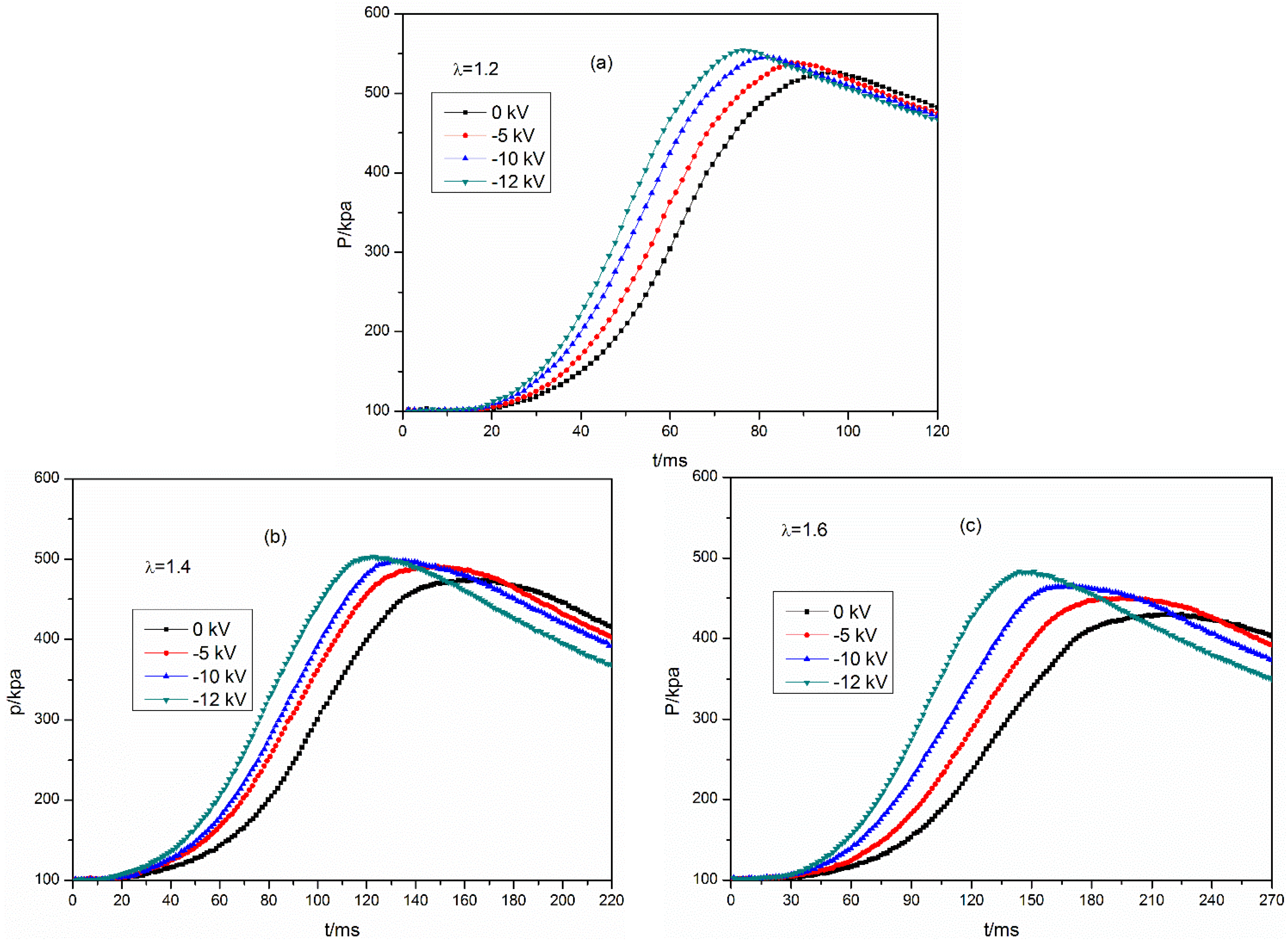
Figure 9 shows the combustion pressure traces under the application of the electric field. The excess air ratios are 1.2, 1.4 and 1.6 and the input voltages are 0 kV, −5 kV, −10 kV, and −12 kV, respectively. It can be seen that in the case of no electric field, the combustion process grows slower with the excess air ratio increasing. In addition, the corresponding value of peak pressure decreases and the timing of the peak pressure is delayed. When the electric field is applied to the mixture at any excess air ratio, the combustion pressure increases rapidly in the early stage and the corresponding value is higher than that without electric fields. Moreover, the peak combustion pressure increases and the timing of the peak pressure is remarkably advanced compared with that in the absence of the electric field. The higher the input voltage, the greater effect of the applied electric field on combustion pressure is.
Table 2 shows the maximum combustion pressure
Pmax, the timing of maximum pressure appearance
tp, and their increase rates Δ
Pmax and Δ
tp which compared to the corresponding case of no electric field. It can be seen that the largest increase of
Pmax and the most significant advancement of
tp are presented at λ = 1.6, that for λ = 1.4 the less pronounced and that for λ = 1.2 the smallest. For example, at the input voltage of −12 kV,
Pmax increases by 5.1%, 5.9% and 12.3%, and
tp is advanced by 20.8%, 25.2% and 31.8%, for λ = 1.2, 1.4 and 1.6, respectively, compared to the corresponding case of no electric fields.
Figure 9.
The combustion pressure records under various conditions. (a) λ = 1.2, (b) 1.4, (c) 1.6 with the voltages of 0, −5, −10, −12 kV.
Figure 9.
The combustion pressure records under various conditions. (a) λ = 1.2, (b) 1.4, (c) 1.6 with the voltages of 0, −5, −10, −12 kV.
Table 2.
Combustion characteristics and the increase rates for various excess air ratios.
Table 2.
Combustion characteristics and the increase rates for various excess air ratios.
| U (kV) | λ = 1.2 | λ = 1.4 | λ = 1.6 |
|---|
| Pmax (kPa) | ΔPmax (%) | tP (ms) | ΔtP (%) | Pmax (kPa) | ΔPmax (%) | tP (ms) | ΔtP (%) | Pmax (kPa) | ΔPmax (%) | tP (ms) | ΔtP (%) |
|---|
| 0 | 527.7 | 0 | 95.8 | 0 | 475.2 | 0 | 163.8 | 0 | 430.4 | 0 | 217.2 | 0 |
| −5 | 538.8 | 2.1 | 89.5 | −6.6 | 491.7 | 3.5 | 144.5 | −11.8 | 450.5 | 4.7 | 191.8 | −11.7 |
| −10 | 546.9 | 3.7 | 81.6 | −14.7 | 498.4 | 4.9 | 133.9 | −18.2 | 465.9 | 8.3 | 167.5 | −22.9 |
| −12 | 554.7 | 5.1 | 75.8 | −20.8 | 503.4 | 5.9 | 122.5 | −25.2 | 483.5 | 12.3 | 148.1 | −31.8 |
The previous sections of this paper concerning the flame propagation have shown that the applied electric fields can accelerate the flame propagation velocity, and the effects increase with the increase of the input voltage. Thus, the whole combustion process is accelerated compared with the case of no electric field. As a consequence, the combustion pressure in initial stage period grows up fast and high, and
tp at any excess air ratio is advanced obvious. The larger the increase of flame propagation speed, the greater
tp is advanced. The increase of peak combustion pressure under the influence of applied electric field is most likely related to the heat release of combustion and the heat loss to the bomb [
24]. As stated before, the applied electric field can augment the positive hydrodynamic stretch in flame (toward the unburned zone), and this result will increase the local volumetric burning rate. Additionally, in the region near the needle tip with intense electric field, the ionic wind effects induce the flame front to appear wrinkles and distortions, and this further enlarge the flame front area and improve the burning rate of combustible mixture. On the other hand, the field-induced flame stretch can strongly influence the flame response and structure for mixtures with unequal diffusivities [
32]. For a stretched flame, the reaction zone in the stretched surface loses thermal energy to the external unburned gas while it gains chemical energy from them due to an increase of deficient reaction concentration. Thus the stretched flame behavior, especially its temperature, depends on the relative rates of heat and mass diffusion. According to the combustion theory, Lewis number (Le) is defined as the ratio of heat diffusivity of the mixture to the mass diffusivity of the deficient reactant. If the heat loss and mass gain are equal such that Le = 1, then the total energy is conserved and the flame temperature is the adiabatic temperature. However, if mass gain exceeds heat loss (Le < 1), then there will be more intensified burning on the stretched surface such that the flame temperature is higher than the adiabatic temperature. Conversely, if Le > 1, the flame temperature is lower than the adiabatic flame temperature. In the case of lean methane-air mixture, Le < 1,
i.e., the mass diffusion exceeds the thermal diffusion. Based on the influence of the non-unity Lewis number in the burning intensity of stretched flames, the field-induced flame stretch will cause the burning more strong and the flame temperature increase. Previous studies [
32,
33] conducted on methane–air flames also demonstrated that the positive flame stretch can lead to the flame temperature increase at Le < 1. This argument still holds even if we just consider the relative mass diffusivities of the fuel and oxidizer. Based on molecular weight considerations, the diffusivities of methane and oxygen relative to nitrogen decrease in turn. Thus positive flame stretch will increase the methane concentration of a lean methane-air mixture at the flame. The reaction zone is consequently rendered more stoichiometric, leading to the enhanced burning intensity. In addition, the increase of flame speed under the electric field markedly enhances the whole combustion process, and shortens the overall combustion duration. Therefore, the heat loss from the flame to the bomb wall could decrease. The combined influence of the above factors gives
Pmax increase relative largely for lean methane–air mixtures. The effect of the electric field on combustion pressure at leaner mixture is more pronounced because the electric field-induced stretch in flame is relatively greater in this case.
3.5. Influence of the Electric Field on the Heat Release Rate
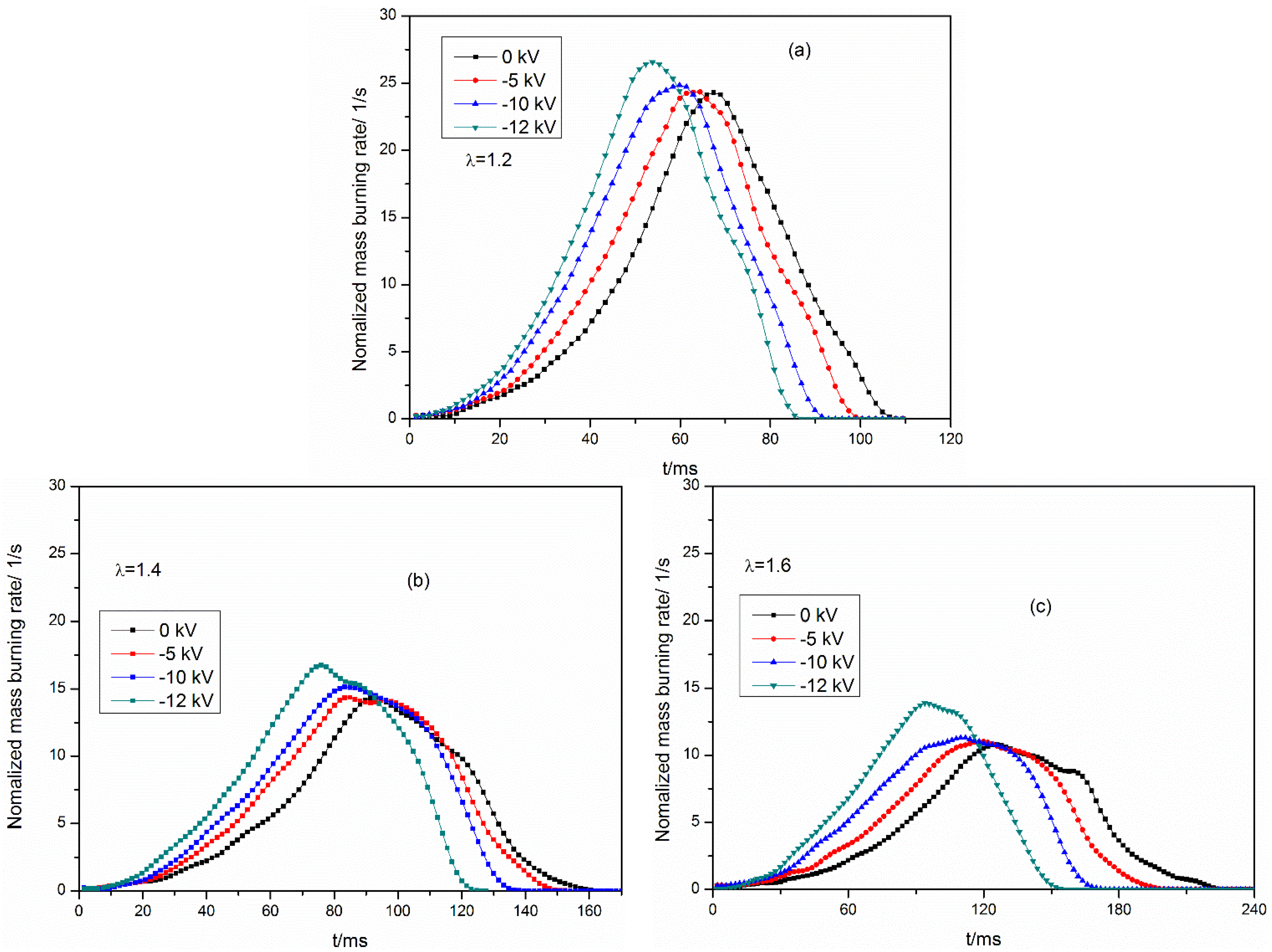
In order to further figure out the effect of the applied electric field on the combustion process,
Figure 10 gives the normalized mass burning rate at λ = 1.2, 1.4 and 1.6 under various input voltages. In this paper, the normalized mass burning rate is defined as (1/
m)(d
mb/d
t), which is calculated based upon foregoing two-zone mode and reflects the burning velocity of the mixture during the combustion process. In the absence of the electric field, the normalized mass burning rate curve has a single peak at any excess air ratio. This illustrates the combustion process flame in the constant volume bomb is mainly based on the premixed mixture burning. For the three excess air ratios, the fast rate and high value of the normalized mass burning rate are presented at λ = 1.2, and the slow rate and low value of the normalized mass burning rate are demonstrated at λ = 1.4 and 1.6 in turn. Under the application of the electric field, the normalized mass burning rate grows up fast, and the whole combustion duration is shortened. Thus, the peak value of the normalized mass burning rate increases, and its appearance time is advanced. Moreover, the enhancement of the normalized mass burning rate for λ = 1.6 is most significant, followed by that at λ = 1.4 and 1.2 in turn. For example, at the applied voltage of −12 kV, the peak value of the normalized mass burning rate increases by almost 9.3%, 16.6% and 28.9%, and its appearance times are advanced by almost 18.5%, 20.2% and 25.4%, for λ = 1.2, 1.4 and 1.6, respectively, when compared to the corresponding case of no electric fields. These results further verify that the electric field can significantly enhance the combustion process of the lean methane–air mixture, and this impact is more pronounced when the excess air ratio is increased. These effects are consistent to the behaviors of pressure records for the three excess air ratios under the electric field.
Figure 10.
Nomalized mass burning rate under various conditions. (a) λ = 1.2, (b) 1.4, (c) 1.6 with the voltages of 0, −5, −10, −12 kV.
Figure 10.
Nomalized mass burning rate under various conditions. (a) λ = 1.2, (b) 1.4, (c) 1.6 with the voltages of 0, −5, −10, −12 kV.
Figure 11 gives the accumulated mass fraction burned at λ = 1.2, 1.4, and 1.6 under various input voltages. When the electric field is applied to the mixture at any excess air ratio, the accumulated mass fraction burned grows up fast with the increase of the applied voltage due to the increase of flame propagation speed. According to the combustion theory, the flame development duration (
ta) is the time interval from the spark ignition to the timing that 10% of mass fraction burned is reached; the rapid combustion duration (
tb) is the time interval from 10% mass fraction burned to the timing of 90% mass fraction burned.
Table 3 shows
ta,
tb, and their increase rates Δ
ta and Δ
tb which compared to the corresponding case without electric field. As can be seen, both
ta and
tb are all reduced with the increase of the applied voltage, and the effect for leaner mixture is more significant. For example, at the input voltage of −12 kV,
ta are decreased by almost 22.3%, 26.2% and 31.5%, and
tb are decreased by 12.6%, 16.0% and 20.8%, for λ = 1.2, 1.4 and 1.6, respectively, compared to the corresponding case of without electric field. This reveals the fact the electric field can enhance the burning speed of the lean methane-air mixture, especially it gives larger influence on decreasing the flame development duration.
Figure 11.
Mass fraction burned as a function of time under various conditions. (a) λ = 1.2, (b) 1.4, (c) 1.6 with the voltages of 0, −5, −10, −12 kV.
Figure 11.
Mass fraction burned as a function of time under various conditions. (a) λ = 1.2, (b) 1.4, (c) 1.6 with the voltages of 0, −5, −10, −12 kV.
Table 3.
Flame development duration and rapid combustion duration and their increase rates for λ = 1.2, 1.4 and 1.6.
Table 3.
Flame development duration and rapid combustion duration and their increase rates for λ = 1.2, 1.4 and 1.6.
| U (kV) | Flame Development Duration | Rapid Combustion Duration |
|---|
| λ = 1.2 | λ = 1.4 | λ = 1.6 | λ = 1.2 | λ = 1.4 | λ = 1.6 |
|---|
| ta (ms) | Δta (%) | ta (ms) | Δta (%) | ta (ms) | Δta (%) | tb (ms) | Δtb (%) | tb (ms) | Δtb (%) | tb (ms) | Δtb (%) |
|---|
| 0 | 39.9 | 0 | 57.3 | 0 | 74.7 | 0 | 47.5 | 0 | 73.3 | 0 | 96.6 | 0 |
| −5 | 36.7 | −8.0 | 51.8 | −9.6 | 66.2 | −11.4 | 45.2 | −4.8 | 69.5 | −5.2 | 90.7 | −6.1 |
| −10 | 32.8 | −17.8 | 46.1 | −20.0 | 56.2 | −24.8 | 43.2 | −9.1 | 66.0 | −10.0 | 85.2 | −11.8 |
| −12 | 31.0 | −22.3 | 42.3 | −26.2 | 51.2 | −31.5 | 41.5 | −12.6 | 61.6 | −16.0 | 76.5 | −20.8 |


