1. Introduction
Features such as low investment, environmental friendliness, high reliability and flexibility make distributed generation (DG) systems an interesting and promising technological option [
1,
2,
3]. As power systems are seeing an increasing DG penetration level, beside the aforementioned advantages, DG units may also bring problems to the utility grid like bidirectional power flow, voltage deviations, and voltage fluctuations. In this sense, a microgrid, which consists on a cluster of loads and parallel-connected DG units in a local area [
4,
5] is a suitable solution to problems caused by the high DG penetration, thus making possible large-scale DG penetration [
6,
7]. A microgrid can be connected to the utility grid at the point of common coupling (PCC), being able to flexibly import/export energy from/to the grid by controlling active and reactive power flows [
8,
9]. When there is a fault in the utility grid or during maintenance, according to IEEE standard 1547.4 [
10], the microgrid must be disconnected from the utility grid, thus operating in islanded mode in order to guarantee the electrical power supply to the critical loads [
11,
12].
In general, the normal DG operation mode is performed connected to the grid, since in this case maximum produced power can be injected into the grid [
13,
14]. The control algorithms for grid-connected DGs have been developed and refined over the years [
15,
16]. Blaabjerg [
17,
18] presented an overview of different control and synchronization techniques for DG systems [
19]. Different control strategies for DG systems under unbalanced condition are given in. Savaghebi, Castilla and Twining [
20,
21,
22] proposed different controllers for DG systems to compensate harmonic components. Guerrero designed control schemes for parallel connected DGs [
23,
24,
25], hierarchical control is discussed in [
26,
27]. Nowadays these control schemes are mature technologies that are available on the market. Therefore, a real microgrid plant often uses commercial DG systems and adds extra customized equipment to provide extra functionalities.
This paper proposes a “microgrid stability controller” (MSC) based on energy storage equipment, which provides islanding operation functionality to conventional DG systems without changing their grid-connected control strategies. In addition, in grid-connected mode, the MSC can smooth the exchanged power at the PCC, thus avoiding voltage fluctuations and other power quality issues in the main grid. This feature is important when prime movers are renewable energy sources which are characterized by having a stochastic and intermittent behavior.
The MSC is expected to operate with high efficiency, low output current total harmonics distortion, and sinusoidal output voltage with a specified frequency and amplitude in all operation modes. In addition to this requirement, the MSC must be robust against disturbances, having good voltage regulation and fast dynamic response. In that sense, many control techniques have been proposed for pulse width modulation (PWM) converters to achieve good dynamic response under different types of loads, including proportional-integral-derivative control, model-based linear control, robust control, and internal model principle based control [
28,
29,
30]. However, uncertainties caused by the operation mode transitions and DG disturbances make the MSC a nonlinear, time-variable system. Therefore, it is difficult to reach ideal control objectives with conventional control techniques due to their multivariable structure and highly coupled nonlinearity of the system. Most of the conventional control techniques only guarantee the desired closed-loop response at the expected operating point, thus degrading their performances outside this point. Hence, it seems natural to explore other nonlinear controls that can overcome the uncertainties problem, and to achieve better compensation and global stability in large-signal sense [
31].
For instance, sliding mode control (SMC) is one of the most effective nonlinear robust control approaches, since it provides to the system a dynamics with an invariance property to uncertainties once the system dynamics is controlled in the sliding mode [
32,
33,
34,
35,
36]. Reference [
37] applies the SMC scheme to a three-phase AC-to-DC voltage source boost converter to provide a constant level output voltage while keeping unity power factor. Reference [
38] applies SMC in a single phase inverter and designs different control schemes in stand-alone and grid connected modes. Reference [
39] uses SMC in the voltage control loop of a voltage-sourced rectifier, which provides quasi unity power factor operation, low harmonic content and fast dynamic response. While hysteretic control is applied in the current control loop, so that the switching frequency is variable, also named
chattering.
In practical control systems, parameter variation, uncertainties, external disturbances and the limitation of detection make it difficult to acquire an accurate mathematical model. Consequently, the traditional SMC can hardly achieve outstanding results. Therefore, this work proposes an adaptive robust total sliding-mode control (ARTSMC) system for the MSC, which colligates the advantages of adaptive control and SMC. The total sliding surface eliminates the control error and gets a sliding motion through the whole state trajectory [
40,
41]. Furthermore, the use of PWM avoids variable switching frequency.
This paper is organized as follows: in
Section 2 the configuration of a microgrid including the proposed MSC is presented. In
Section 3 the model of the proposed MSC is derived for the system operating in both islanded and grid-connected modes.
Section 4 presents the ARTSMC system for both voltage control and current control used in islanded and grid-connected modes respectively.
Section 5 validates the proposed approach by means of simulation results, and
Section 6 present the experimental results extracted by an AERTSMC-controlled MSC of 3 kVA. Finally,
Section 7 concludes the paper.
2. Proposed MSC-Based Microgrid
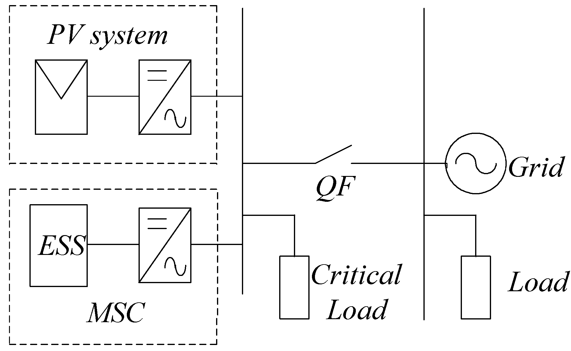
Figure 1 shows the circuit topology of a microgrid including a photovoltaic (PV)-based DG unit and critical loads connected to an AC bus. The microgrid is connected to the electrical distribution network through a circuit breaker
QF. The MSC, which consists of an energy storage system, a bidirectional DC-to-AC converter with an inductor-capacitor (LC) filter, is connected to the AC bus together with the DG unit and the critical load inside the microgrid.
Figure 1.
Microgrid including the proposed MSC.
Figure 1.
Microgrid including the proposed MSC.
As the MSC is based on an energy storage system (ESS) and full controlled converter, it can flexibly import/export power from/to the grid. When the microgrid operates in grid-connected mode, the MSC can compensate the power variations or reduce the power fluctuations caused by the DG unit or the critical loads inside the microgrid. When the microgrid is disconnected from the main grid, thus operating in islanded mode, the MSC fixes the microgrid output voltage and frequency, which are the references to be used by the DG. Note that when the microgrid operates in islanded mode, it is a weak AC power system, consequently, the DG output power variations or load disturbances are more likely to cause voltage fluctuations or voltage sags. These problems may enforce DG units and/or sensitive load disconnection from the AC line. Therefore, it is necessary to use the MSC to balance active and reactive in the microgrid in order to maintain voltage and power quality.
3. MSC Modeling
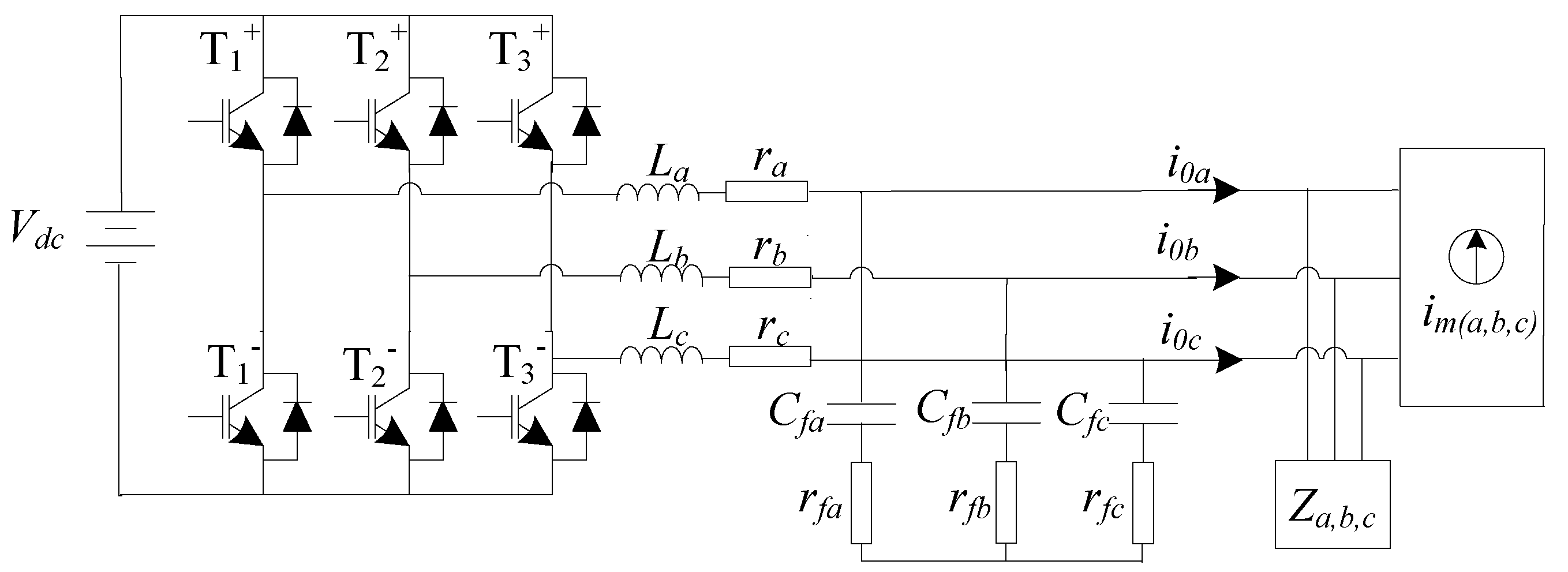
Figure 2 shows the power stage of the MSC when the microgrid operates in islanded mode. In this figure,
v0a,
v0b,
v0c are the AC bus voltages (per phase) and
i0a,
i0b,
i0c are the AC currents (per phase) of the MSC;
La,
Lb,
Lc and
Cfa,
Cfb,
Cfc are the filter inductor and capacitor values, respectively;
ra,
rb,
rc represent the equivalent series resistor (ESR) of the converter, inductor, and power line;
rfa,
rfb,
rfc represent the ESR of the filter capacitor; and
ima,
imb,
imc represent the aforementioned disturbances in the microgrid.
Figure 2.
Power stage of the MSC.
Figure 2.
Power stage of the MSC.
The states of the switches of the n-th leg (n = 1, 2, 3) can be represented by the time-dependent variable Sn, defined as:
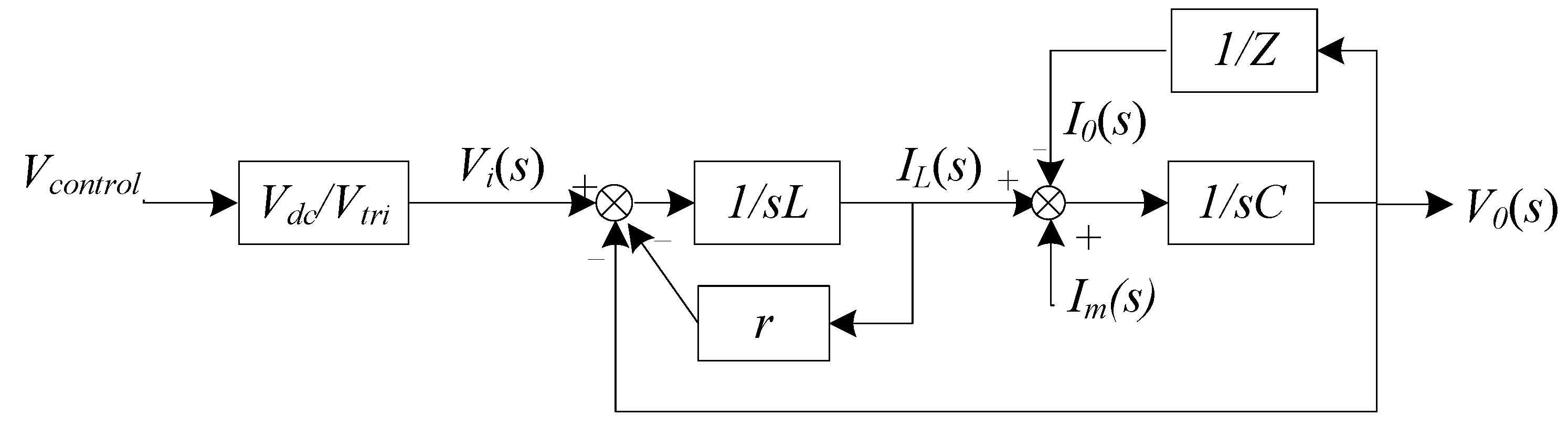
This switching strategy, together with a small dead-time generator, will avoid internal shorts between the two switches of each bridge leg, as the switches will always be in complementary states. Assuming that the switching frequency is high enough compared to the modulation and natural frequencies, the equivalent dynamic model of
Figure 2 can be obtained as shown in
Figure 3, where
s is the Laplace operator, the power gain can be defined as
kPWM =
Vd/vtri, and
vtri is the amplitude of a triangular carrier signal.
Figure 3.
Equivalent dynamic model.
Figure 3.
Equivalent dynamic model.
3.1. System Modeling in Islanding Mode
When the microgrid operates in islanded mode, the dynamic Equation of the MSC during the positive-half period can be represented as:
where
,
,
,
,
,
,
,
,
,
vcontrol1k is the control signal,
k = a, b, c.
According to the aforementioned discussion, the microgrid is a nonlinear, time-variable system and there are uncertainties in the MSC system, which are caused by parametric variations or external disturbances. Therefore, Equation (2) should be modified as follows:
∆Ak,
∆Bk,
∆Dk represent the system parameter variations and they satisfy the matching condition which is
∆Ak =
BkGk,
∆Bk =
BkHk,
∆Dk =
BkJk,
FkImk =
BkKk. In order to analyze conveniently, define:
Thus, rearranging Equation (4) as:
The bound of the uncertainty is assumed to meet the following inequality:
where
q1k and
q2k are unknown positive constants and
ek is the voltage control error, which is defined as:
where
vrefk is the output voltage reference, which is set to the nominal value.
3.2. System Modeling in Grid-Connected Mode
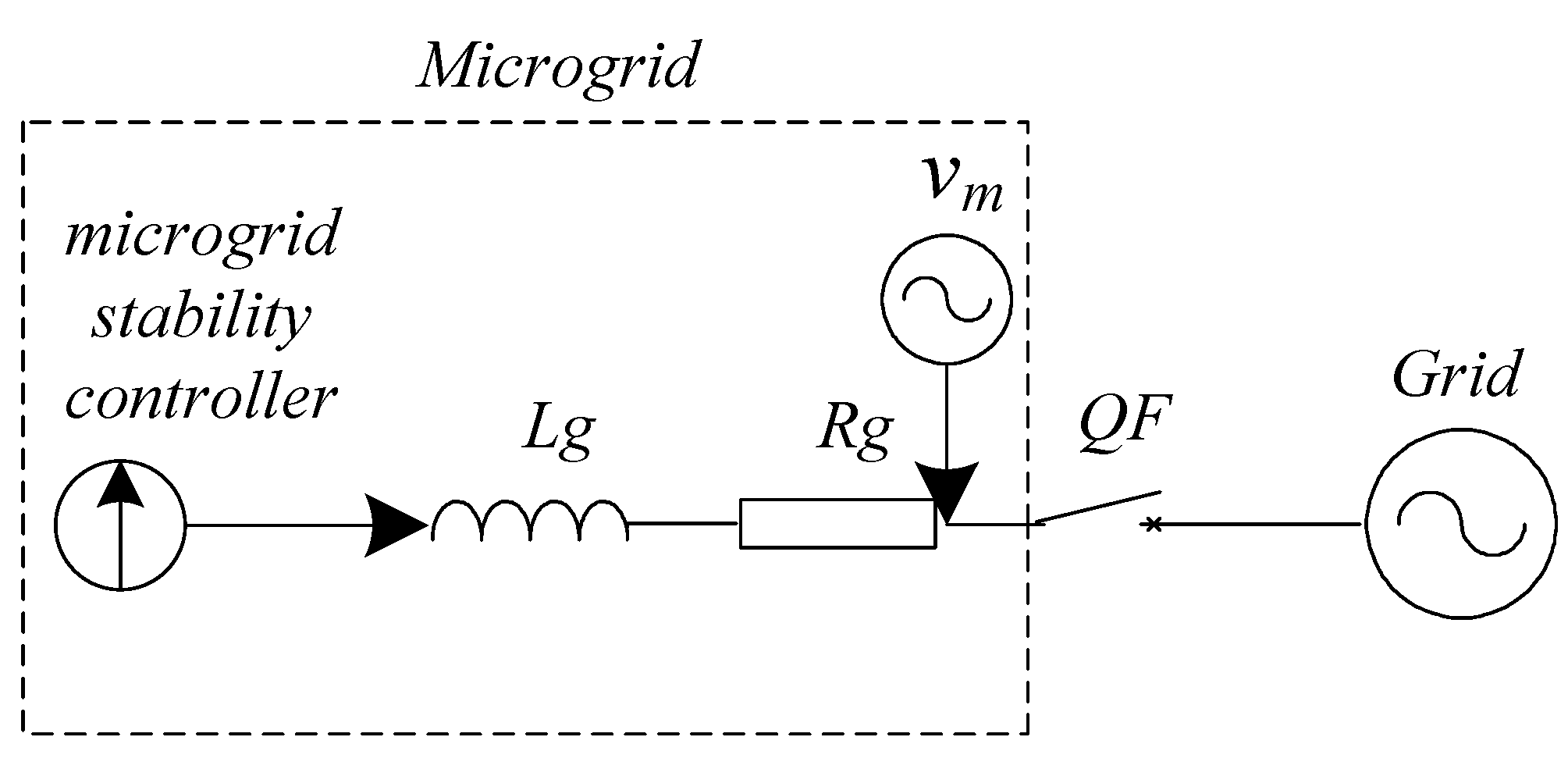
When the microgrid operates in grid-connected mode, it is connected to the utility grid through
QF as shown in
Figure 4.
Figure 4.
Block diagram of the grid-connected microgrid.
Figure 4.
Block diagram of the grid-connected microgrid.
In order to provide the desired power to the grid, we propose use the MSC to compensate power variations and to reduce power fluctuations caused by the DGs and/or loads in the microgrid. The dynamic Equation of the MSC during the positive-half period is represented as:
Equation (8) can be rearranged as follows:
where
Lg =
diag(
Lga,
Lgb,
Lgc),
i0 =
diag(
i0a,
i0b,
i0c),
Rg =
diag(
Rga,
Rgb,
Rgc),
,
v0 =
diag(
v0a,
v0b,
v0c),
vm =
diag(
vma,
vmb,
vmc), being
ucontrol2 =
diag(
ucontrol2a,
ucontrol2b,
ucontrol2c) the control signal;
Lga,
Lgb,
Lgc and
Rga,
Rgb,
Rgc represent inductors and their respective ESRs;
v0a,
v0b,
v0c and
i0a,
i0b,
i0c are the AC voltage and current (per phase) respectively; and
vma,
vmb,
vmc represent disturbances or uncertainties in the microgrid. Equation (9) can be rearranged as:
where
a =
diag(−
Rga/
Lga, −
Rgb/
Lgb, −
Rgc/
Lgc),
b =
diag(
kPWM/
Lga,
kPWM/
Lgb,
kPWM/
Lgc),
c =
diag(−1/
Lga, −1/
Lgb, −1/
Lgc). Due to the parametric variations or external disturbances, Equation (10) should be modified as:
∆a,
∆b,
∆c represent the system parameter variations and they satisfy the matching condition which is
∆a =
bf,
∆b =
bm,
∆c =
bn,
vm/Lg =
bg. In order to analyze conveniently, define:
where
w is the uncertainty. Therefore Equation (11) is modified as:
The bound of the uncertainty is assumed to meet the following inequality:
Being q = diag(qa, qb,q c) an unknown positive constant.
4. ARTSMC System
The proposed ARTSMC is insensitive to parametric uncertainties and external disturbances. The total sliding surface ensures stability and robustness through the entire state trajectory. Hence, the system dynamics in the reaching phase is not influenced by uncertainties. The control law encompasses a state feedback term, a robust control term, and an adaptive compensation term. The state feedback term takes advantage of the pole assignment and state feedback, while simplifying the sliding surface design. The robust control term decides the basic structure of the uncertain nonlinear system. Uncertainties in the MSC system do not have a fixed value, so that it is difficult and impractical to measure real-time uncertainties. Thus, a logical solution is to apply an adaptive strategy. Instead of fixing a boundary of uncertainties, an adaptive compensation term is introduced in order to adjust the uncertainties in real-time. According to the difference between the nominal nonlinear system and the uncertain nonlinear system, the sliding surface and other parameters compose the adaptive law which satisfies the global Lyapunov stability condition.
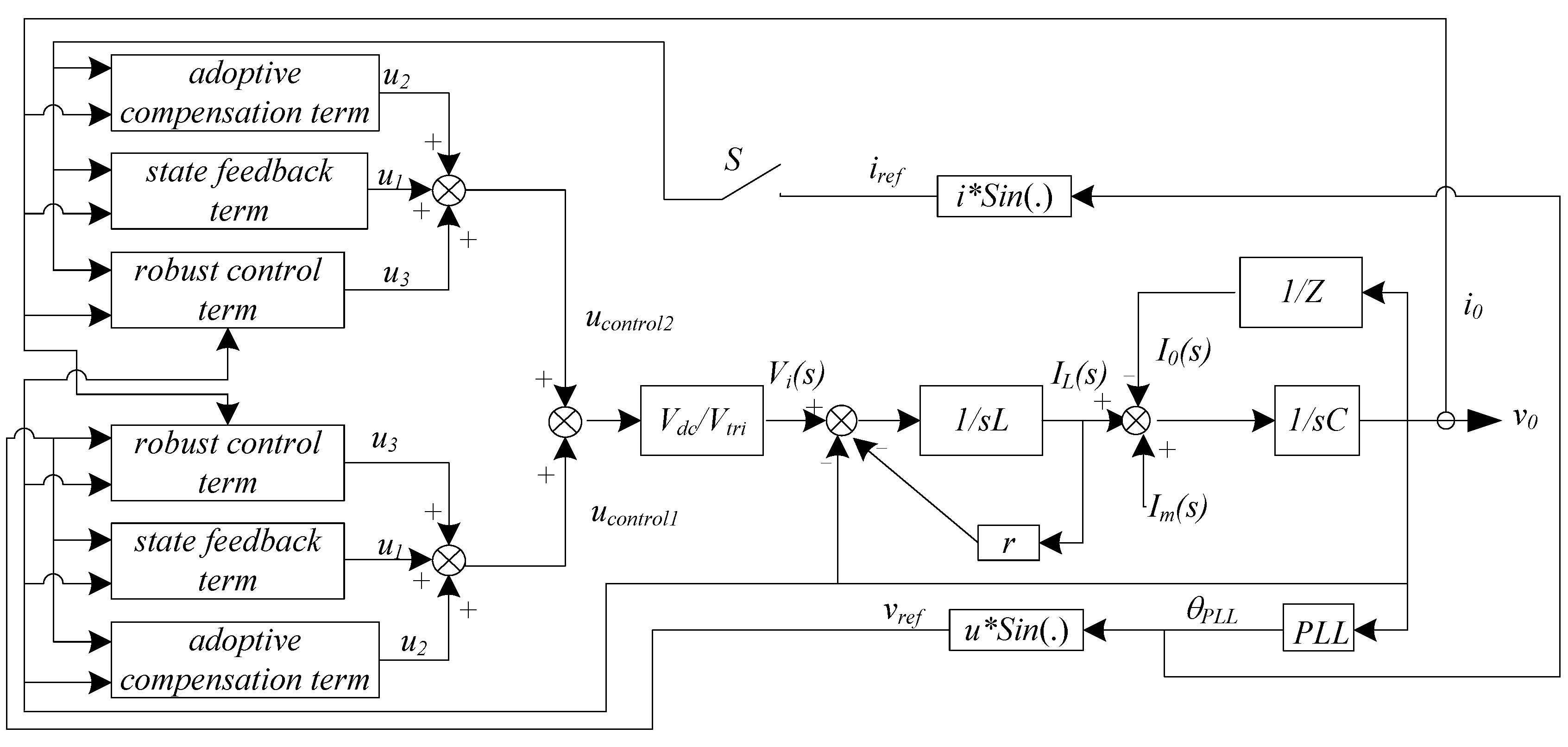
The proposed ARTSMC system is divided into two main parts, as illustrated in
Figure 5. The first part is the ARTSMC based voltage control loop, which produces the control signals
ucontrol1a,
ucontrol1b and
ucontrol1c. The second part is the ARTSMC based current control loop, which produces the control signals
ucontrol2a,
ucontrol2b, and
ucontrol2c. When the microgrid operates in grid-connected mode, the current control loop determines the output power of the MSC by controlling its output current. In this scenario, its output voltage
v0a,
v0b, and
v0c is equal to the grid voltage (
vga,
vgb,
vgc), which is assumed to be the nominal value, meaning that
v0a,
v0b,
v0c equal to
vrefa,
vrefb,
vrefc, thus the voltage control loop is automatically disabled. When the microgrid operates in islanded mode, the voltage control loop enforces the output voltage of the MSC to track the reference value
vrefa,
vrefb,
vrefc and to keep the microgrid voltage constant. The output power of the MSC is determined by the power balance among DGs, loads, and losses in the microgrid. Under this circumstance, the current control loop is not necessary and therefore the switch
S is open.
Figure 5.
Block diagram of the MSC model and its ARTSMC.
Figure 5.
Block diagram of the MSC model and its ARTSMC.
4.1. ARTSMC Based Current Control Loop
The main task of the ARTSMC-based current control loop is to control the output power of the MSC by regulating its AC current. Specifically, it has to enforce
i0a,
i0b,
i0c to track the output current reference
irefa,
irefb,
irefc. Thus, a PLL structure is applied in order to generate the output current reference
irefa,
irefb,
irefc, to achieve unity power factor. It is important to notice that the power factor can be adjusted by modifying θ
PLL. The current control loop is synthesized as follows. The first step is to define a sliding surface [
35,
36]:
where
ei =
diag(
i0a−
irefa,
i0b−
irefb,
i0c−
irefc),
s =
diag(
sa,
sb,
sc) and β is the state feedback coefficient.
eio is the initial state of
ei. The second step is to design the control to enforce the system state trajectories to go toward the sliding surface (15) and to stay on it:
where:
Being
u1 the state feedback term,
u2 the robust control term, and
u3 the adaptive compensation term; ε is a small positive constant number;
sign(s) =
diag(
sign(
sa),
sign(
sb),
sign(
sb)) and
sign(·) is the sign function;
abs(·) is the absolute value function;
is the estimated value of
q; the parameter deviation is defined as
; and the adaptive law is:
Proof: The existence condition of the sliding mode can be derived by using Lyapunov stability analysis, by consider the Lyapunov function candidate as:
By taking the derivative of Equation (15) along Equation (13) and substituting Equation (16) and Equation (20) into Equation (22), it yields:
Therefore, , when . It implies that the asymptotically stable behavior for the sliding mode system on the sliding surface (15) can be ensured.
Once the system trajectory reaches the sliding surface,
:
Then, the equivalent control can be obtained from the following equation:
By substituting Equation (24) into Equation (13), it yields:
It implies that by properly selecting the state feedback coefficient β, the robustness of sliding mode (25) can be guaranteed, and the main dynamics features of the MSC such as rising time and maximum overshoot can easily be designed.
4.2. ARTSMC Based for Voltage Control Loop
The main function of the ARTSMC-based voltage control loop is to force the MSC output voltage to track its reference value
vrefa,
vrefb,
vrefc, thus keeping the microgrid voltage constant when the microgrid operates in islanded mode. In order to eliminate the control error and to get a sliding motion through the entire state trajectory, let us define a sliding surface as:
where
C is a full rank constant matrix,
CB is nonsingular, and
β is state feedback control coefficient matrix,
eko is the initial value of
ek. The system state trajectories are forced toward the sliding surface (26) and stay on it, by designing the control scheme as follows such that:
where:
where
u1k is the state feedback term,
u2k is the robust control term,
u3k is the adaptive compensation term;
;
ε is a small positive constant and sign(·) is the sign function;
,
are estimated values of
,
. The parameter deviations are
,
. Choose adaptive law as:
Proof: By considering a Lyapunov function candidate as:
Taking the derivative of Equation (31):
Substituting Equation (27) into (32), it yields:
Consequently, the asymptotically stable behavior for the sliding mode system on the sliding surface (26) can be guaranteed.
Once the system trajectory reaches the sliding surface:
Therefore, the equivalent control can be obtained from Equation (34) which is:
Substituting Equation (34) into Equation (5), it yields:
This implies that with a properly designed state feedback coefficient β, the robustness of sliding mode (35) can be determined. The strictly logical and rigorous proof illustrates the ARTSMC system is insensitive to parametric uncertainties and external disturbances.
5. Simulation Results
A simulation platform under PSCAD/EMTDC environment is developed based on
Figure 1 to study the performance of the MSC and to verify the proposed ARTSMC system.
Table 1 shows the electrical parameters of MSC under study. The AC output voltage reference
vref is set to 220 V at 50 Hz, and the AC output current reference
iref is set according to the desired power exchange value at the PCC. Based on the sliding surfaces (15) and (26), the state feedback coefficients are designed to guarantee the robustness of the sliding modes (25) and (35), while determining the control performance and system stability, the parameters are given as: β = 30, β = [0.00270]. The
DGPV system in
Figure 1 is connected to the same AC bus with the MSC through a DC-to-AC inverter, which is in phase with the grid voltage, and injecting power to the microgrid.
Table 1.
Parameters of the MSC.
Table 1.
Parameters of the MSC.
| Parameter | Value |
|---|
| DC voltage (Energy storage equipment) | 800 V |
| filter capacitance | 3 μF |
| filter inductance | 1.5 mH |
| output voltage (RMS) (phase) | 220 V |
| output frequency | 50 Hz |
The microgrid operates in grid-connected mode and delivers 30 kW to the power grid. The output power of DGPV is set to 40 kW and the critical load inside the microgrid is 30 kW. At 0.5 s, the output power of DGPV increases to 50 kW and at 1 s the microgrid disconnects from the utility, thus operating in islanded mode. At 1.5 s the output power of DGPV decreases to 20 kW, and at 1.75 s the 30 kW critical load is connected to the microgrid.
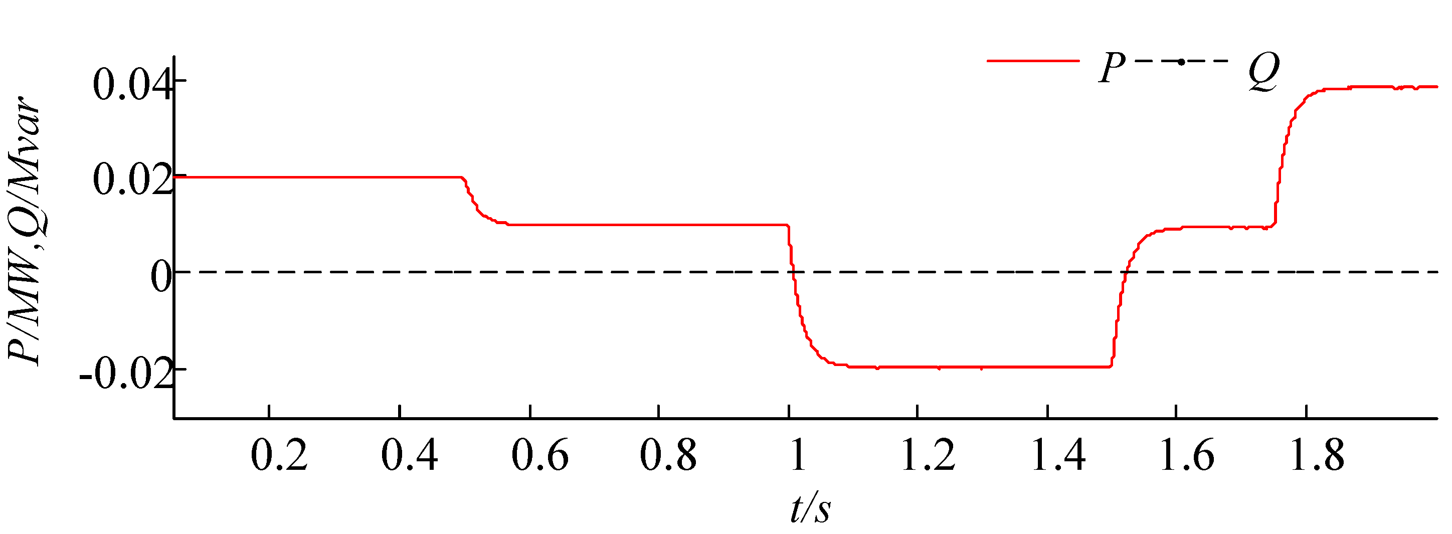
Figure 6 presents output power of the MSC, which is 20 kW at the beginning, and then it goes down to 10 kW at 0.5 s. The MSC switches to charge mode at 1 s as there is 20 kW excess of power when the microgrid operates in islanded mode from 1 s. When the output power of
DGPV decreases to 20 kW at 1.5 s, the MSC starts injecting 10 kW of active power to the microgrid, and its output power raise to 40 kW as the critical load in the microgrid increases to 60 kW at 1.75 s, while the output power of the
DGPV remains constant.
Output active and reactive powers of the MSC.
Figure 6.
Output active and reactive powers of the MSC.
Figure 6.
Output active and reactive powers of the MSC.
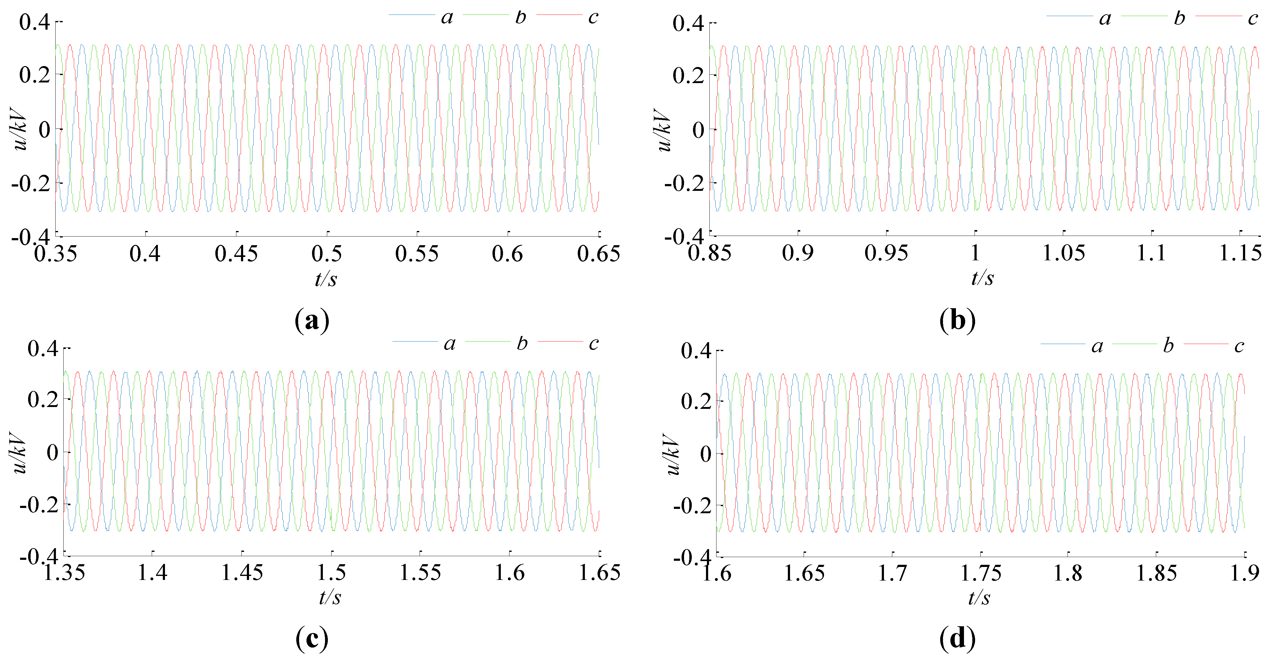
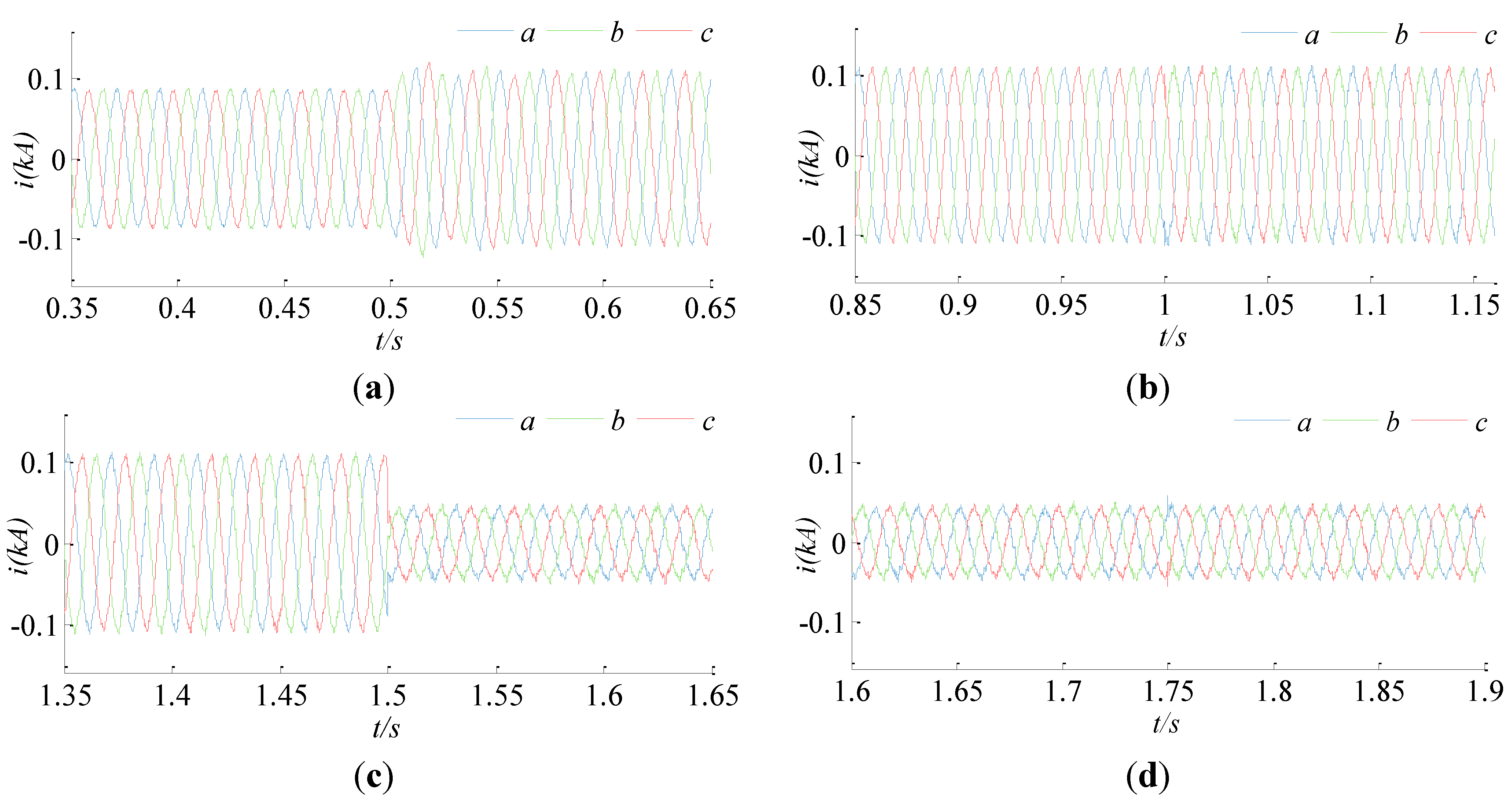
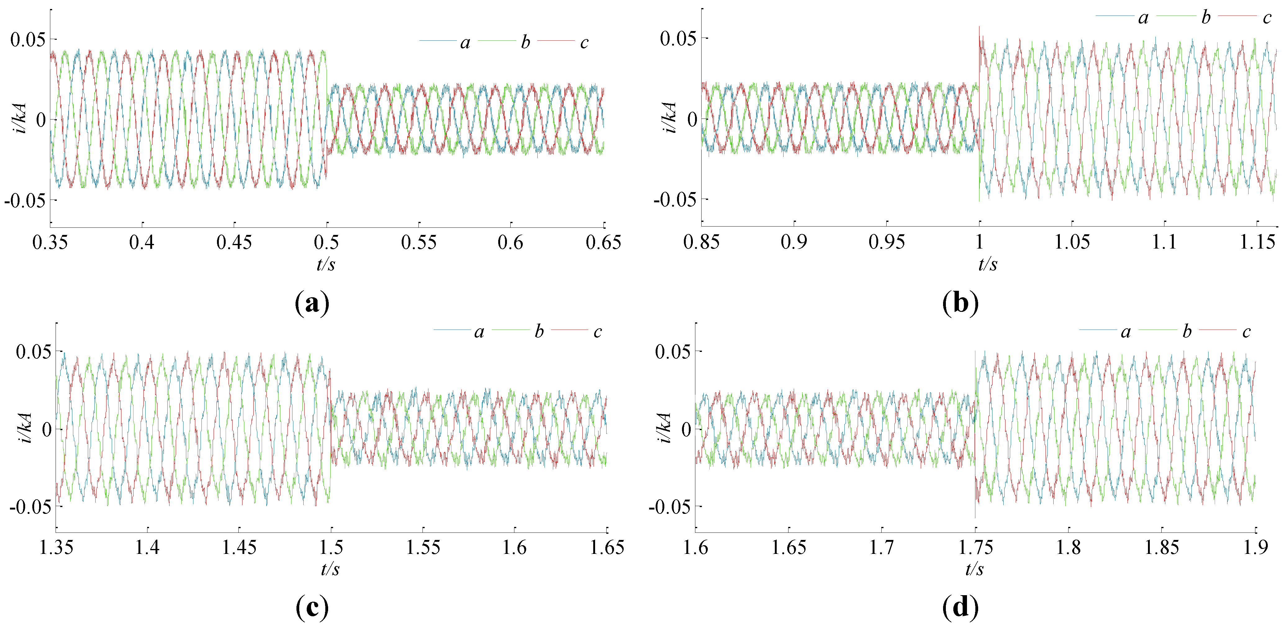
The voltage and current waveforms of the MSC at its AC side are shown in
Figure 7 and
Figure 8. The output current of the MSC does not have any inrush spikes during the entire transition period. Furthermore, there is no voltage perturbation along the operation. Due to the parallel connection of the MSC, the critical load and the
DGPV, the microgrid voltage remains stable in all situations.
Figure 7.
(a) Voltage waveform of the MSC between 0.35 s and 0.65 s; (b) Voltage waveforms of the MSC between 0.85 s and 1.15 s; (c) Voltage waveforms of the MSC between 1.35 s and 1.65 s; (d) Voltage waveforms of the MSC between 1.6 s and 1.9 s.
Figure 7.
(a) Voltage waveform of the MSC between 0.35 s and 0.65 s; (b) Voltage waveforms of the MSC between 0.85 s and 1.15 s; (c) Voltage waveforms of the MSC between 1.35 s and 1.65 s; (d) Voltage waveforms of the MSC between 1.6 s and 1.9 s.
Figure 8.
(a) Current waveforms of the MSC between 0.35 s and 0.65 s; (b) Current waveforms of the MSC between 0.85 s and 1.15 s; (c) Current waveforms of the MSC between 1.35 s and 1.65 s; (d) Current waveforms of the MSC between 1.6 s and 1.9 s.
Figure 8.
(a) Current waveforms of the MSC between 0.35 s and 0.65 s; (b) Current waveforms of the MSC between 0.85 s and 1.15 s; (c) Current waveforms of the MSC between 1.35 s and 1.65 s; (d) Current waveforms of the MSC between 1.6 s and 1.9 s.
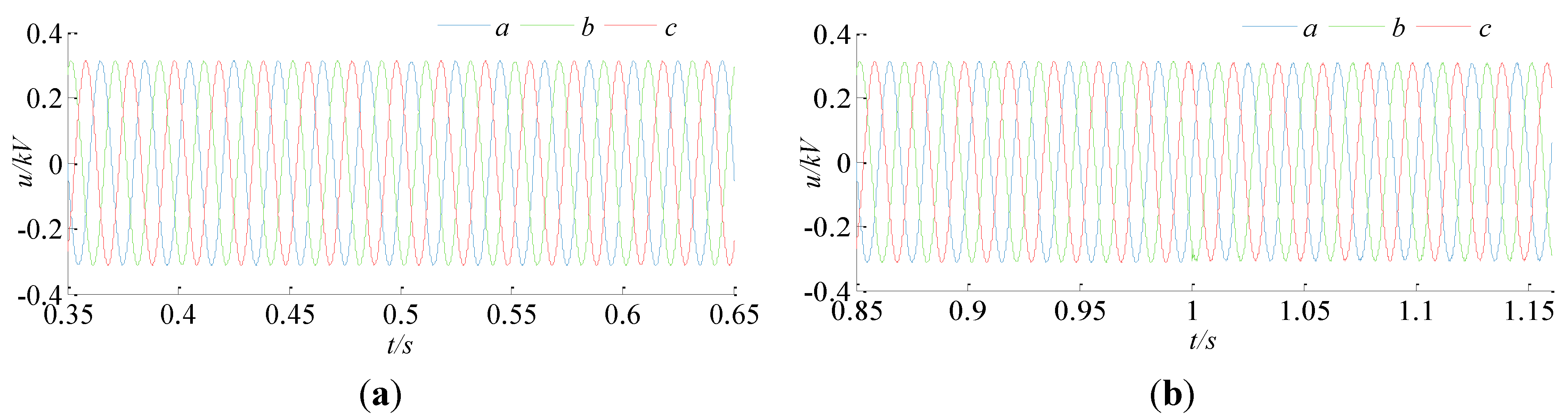
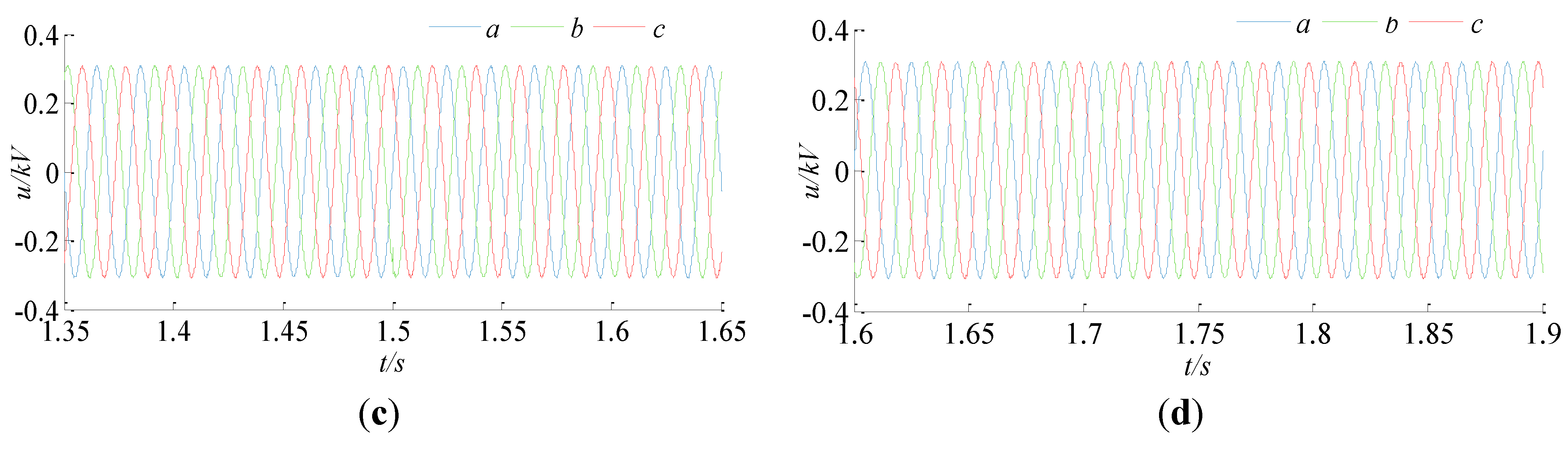
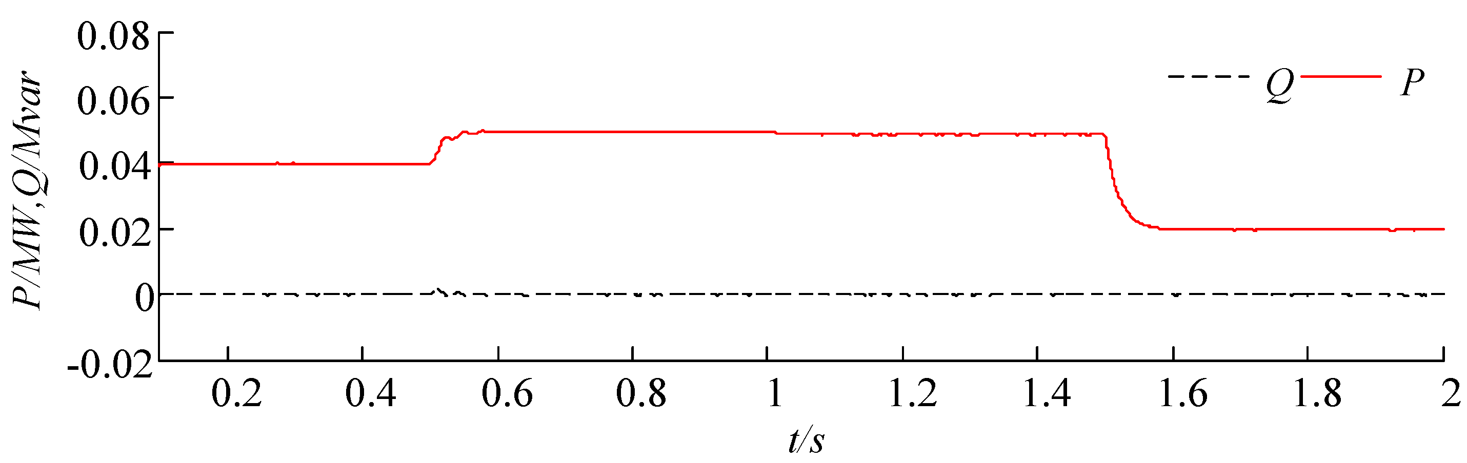
Figure 9 gives the output power of the
DGPV.
Figure 10 and
Figure 11 present the output voltage and current waveforms of the
DGPV. Their output voltage keep steady, while the output current increases at 0.5 s and reduces at 1.5 s with no inrush current. The simulation results indicate smooth transaction and stable operation of the DG system. It shows that MSC provides
DGPV additional islanded operation functionality without changing their inner control strategies conceived for grid-connected mode.
Figure 9.
Output power of the MSC.
Figure 9.
Output power of the MSC.
Figure 10.
(a) Output voltage waveforms of DGPV between 0.35 s and 0.65 s; (b) Output voltage waveforms of DGPV between 0.85 s and 1.15 s; (c) Output voltage waveforms of DGPV between 1.35 s and 1.65 s; (d) Output voltage waveforms of DGPV between 1.6 s and 1.9 s.
Figure 10.
(a) Output voltage waveforms of DGPV between 0.35 s and 0.65 s; (b) Output voltage waveforms of DGPV between 0.85 s and 1.15 s; (c) Output voltage waveforms of DGPV between 1.35 s and 1.65 s; (d) Output voltage waveforms of DGPV between 1.6 s and 1.9 s.
Figure 11.
(a) Output current waveforms of DGPV between 0.35 s and 0.65 s; (b) Output current waveforms of DGPV between 0.85 s and 1.15 s; (c) Output current waveforms of DGPV between 1.35 s and 1.65 s; (d) Output current waveforms of DGPV between 1.6 s and 1.9 s.
Figure 11.
(a) Output current waveforms of DGPV between 0.35 s and 0.65 s; (b) Output current waveforms of DGPV between 0.85 s and 1.15 s; (c) Output current waveforms of DGPV between 1.35 s and 1.65 s; (d) Output current waveforms of DGPV between 1.6 s and 1.9 s.
6. Experimental Results
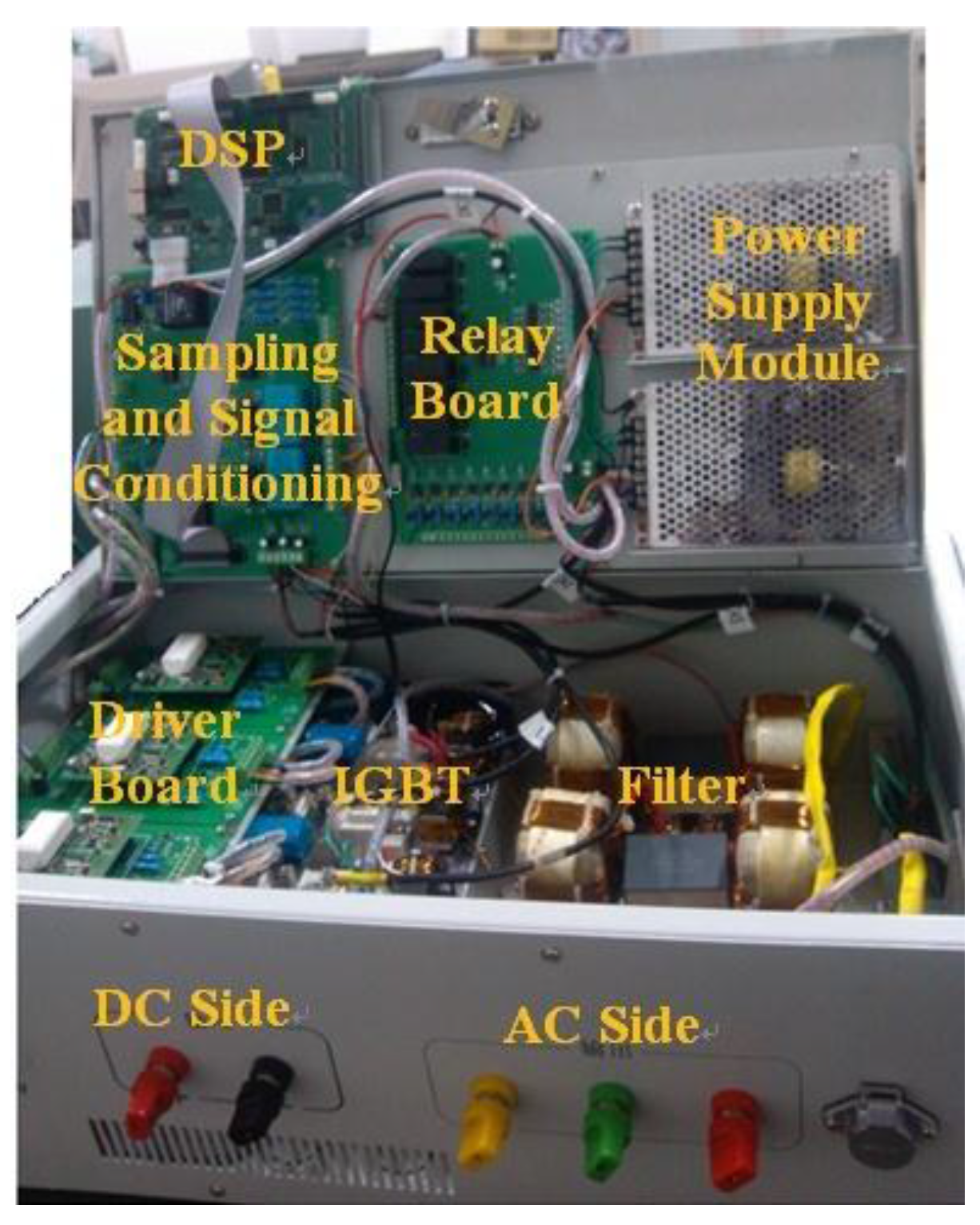
A 3kVA experimental MSC setup is shown in
Figure 12. The converter used in the MSC is built based on IGBTs and the proposed control strategy is carried out by using a digital signal processor (DSP) TMS320F28335 produced by Texas Instruments Inc. (Dallas, TX, USA). The switching frequency of the PWM gating signal is 12 kHz, and the main circuit devices have the same value as in the simulation model.
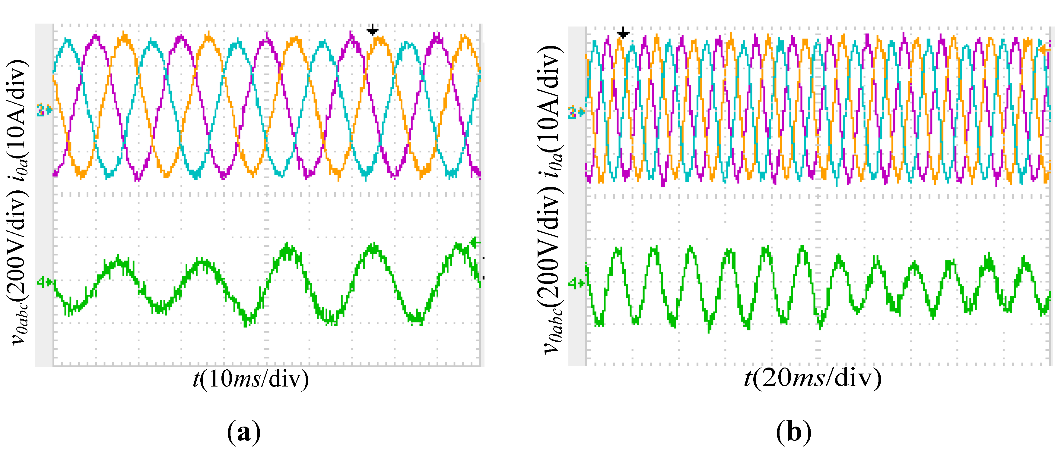
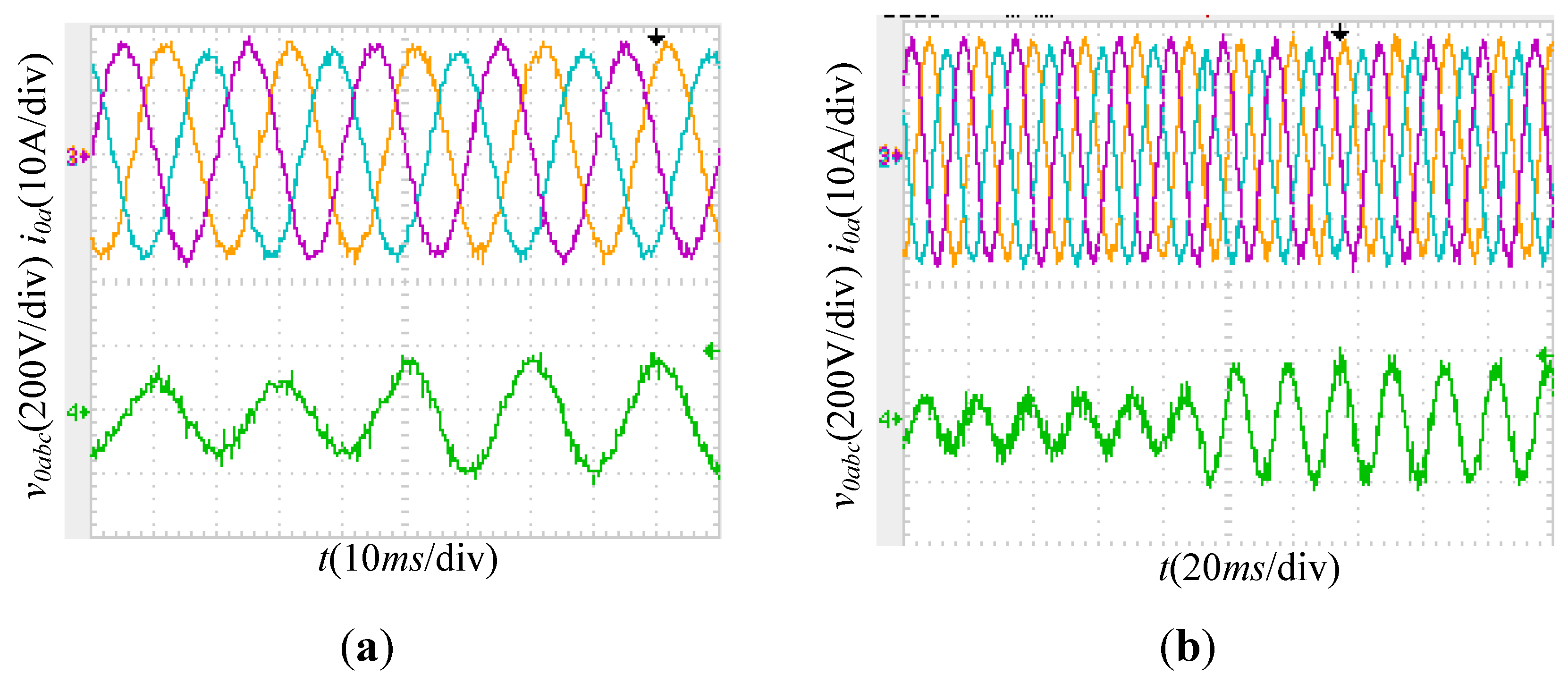
Figure 13 and
Figure 14 give experimental results of the MSC under different conditions. The upper waveform is the voltage waveform of the MSC at the AC side and the lower one is the current waveform of phase A.
Figure 12.
Laboratory setup to test the controller performance.
Figure 12.
Laboratory setup to test the controller performance.
Figure 13.
(a) Experimental results from grid-connected to islanding modes; (b) Experimental results from islanded to grid-connected modes.
Figure 13.
(a) Experimental results from grid-connected to islanding modes; (b) Experimental results from islanded to grid-connected modes.
Figure 14.
(a) Experimental results in grid-connected mode; (b) Experimental results in islanded mode.
Figure 14.
(a) Experimental results in grid-connected mode; (b) Experimental results in islanded mode.
The experimental results of MSC when the microgrid transfers between the two operation modes are shown in
Figure 13. In
Figure 13a, the microgrid operates in grid-connected mode and transfers to islanded mode, while in
Figure 13b the microgrid operates in islanded mode and reconnects to the utility. The output power reference of the MSC is set at 2 kW when the microgrid operates in grid-connected mode. If it is disconnected from the utility grid, the MSC supplies a 3 kW load. It can be seen that in
Figure 13 the output power is controlled to be follow the reference value, and the voltage is controlled to track the voltage reference (220 V, 50 Hz). Note that the output voltage and current of the MSC do not have any inrush spikes during the entire transition period, thus indicating a smooth transition.
Figure 14a presents the experimental results when the microgrid operates in grid-connected mode, the output power reference value of MSC is set at 2.5 kW at first and then increases to 3 kW. Note that its output current is increased and the output voltage is stable. During islanded mode, the MSC feed a 1.5 kW load, and then another 1.5 kW load is connected to the microgrid. The experimental results are given in
Figure 14b, showing clearly that the voltage remains stable during the whole period.


