1. Introduction
In the case of a hydropower station either along a long tailrace tunnel or at a low downstream water level, an open channel often follows the tailrace tunnel [
1,
2]. The adoption of open tailrace channel can make the layout of pipelines easier on the one hand, and can reduce the project investment on the other [
3,
4]. However, the superposition of the gravity wave in an open channel, the mass wave (
i.e., the mass/volume of the fluid in the pipe and surge tank) due to water level fluctuation in the surge tank, and the water hammer wave in the pressurized tailrace tunnel will impact the stability and regulation quality of the hydro-turbine governing system under the condition of load disturbance, and make the operation and regulation of the hydropower station extremely complicated.
For the regulation quality for hydro-turbine governing system of hydropower station without open tailrace channel, many researchers have carried out correlational studies. For instance, Guo
et al. [
5,
6,
7,
8,
9] discussed the effects of a surge tank and penstock on regulation quality. Fu
et al. [
10] studied the dynamic performance of regulation system with a tailrace surge chamber. Wang and Yang [
11] studied the hydraulic control simulation and parameters optimization for water diversion systems. In addition, some novel regulation methods, such as chaos [
12], computational fluid dynamics and visualization [
13] and multivariable generalized predictive theory [
14], have been proposed. But for hydropower stations with open tailrace channel, few current achievements on regulation quality for hydro-turbine governing system can be found.
To evaluate the dynamic performance of the regulation of hydro-turbine governing system in a hydropower station under load disturbance, the whole water and power generation system contain several mathematical sub-models,
i.e., the pipeline, the generator, the turbine, and the governor system [
15,
16,
17]. These mathematical models can be combined in the form of a transfer function to develop an integral governing system along with block diagram for transient numerical simulation and/or for system stability analysis. The water system can always be simulated in the form of a linearized/nonlinear model and is based on either rigid or elastic water hammer phenomenon, but it is only applicable to a pressurized conduit system [
18,
19,
20,
21]. In the case of a partial differential equation for the hydraulic transient in an open channel, it is hard to draw a simple expression of pressure at the cross-section of discharge, in a similar fashion to that of a pressurized conduit system, as the discharge is associated with both the water depth and the flow velocity. Hence, it is difficult to carry out the study on the regulation quality for hydro-turbine governing system of hydropower station without open tailrace channel.
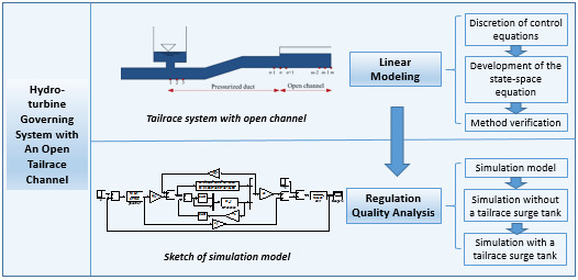
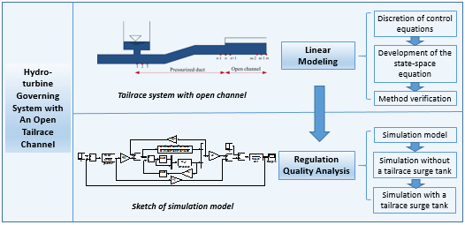
Aiming to overcome the above problem and difficulty, this article: (1) evaluates the sectional linearized discretion of the control equations for the transient flow both for the pressurized conduit and for the open channel, and (2) attempts to develop a response-based relationship between the input and the output quantities at a designated section of the state–space equation. Then, the state equations for the pressurized conduit and the open channel are coupled, and the model of the water system, as either a module of the time-domain simulation or frequency-domain stability analysis of a hydropower station along with the pressurized flow, the open channel system, and the free flow alternative system of surface pressure is improved. This paper is organized as follows.
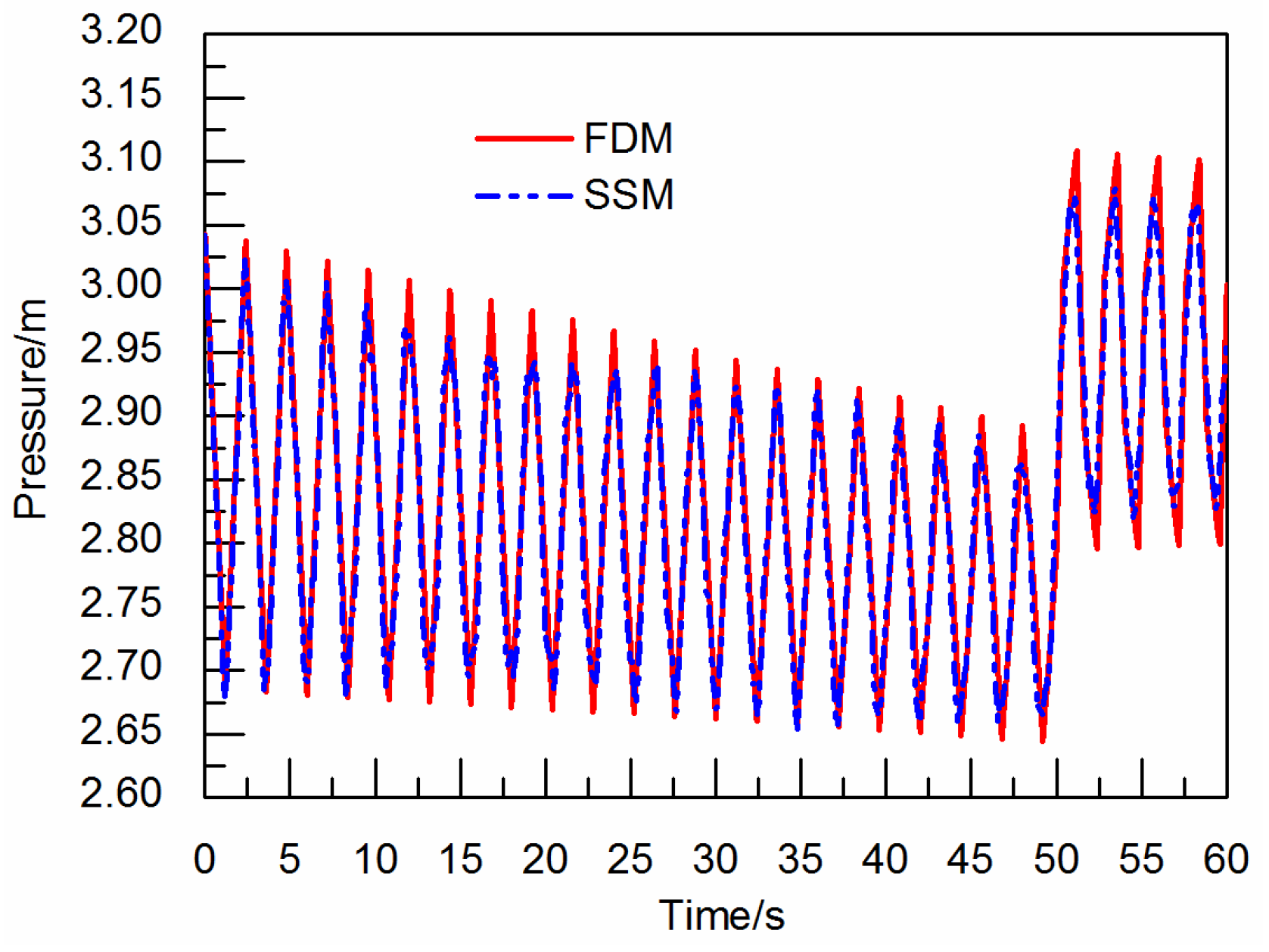
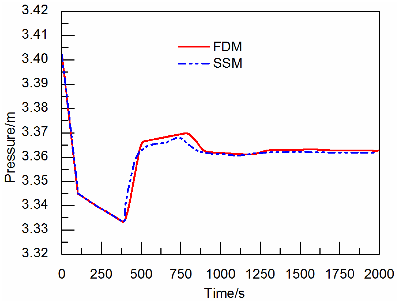
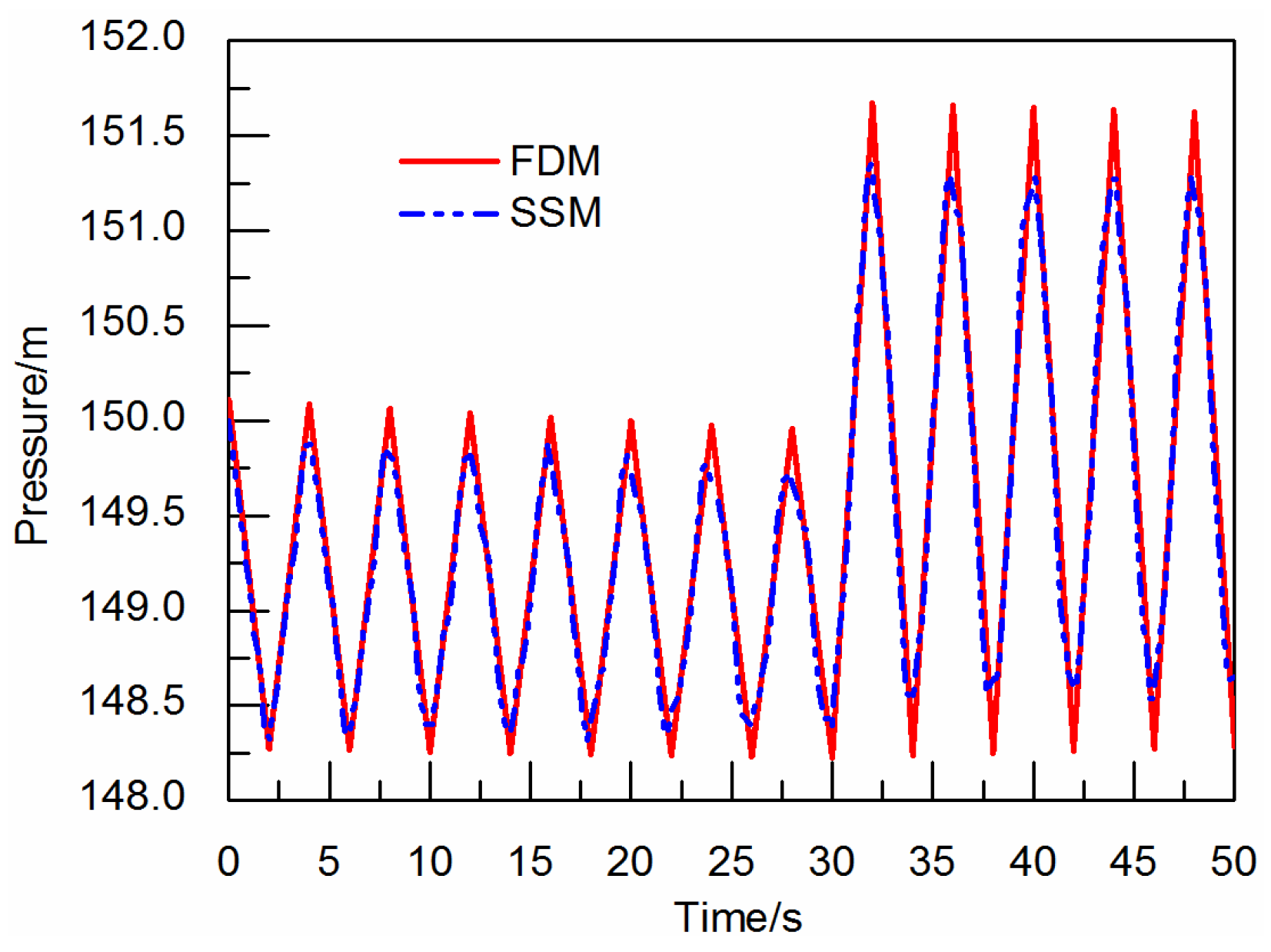
Section 2: on the basis of the state–space method (SSM), a novel linear mathematical model of the unsteady flow for the tailrace system with an open channel is proposed. The validity of the model has been verified by several examples of numerical simulation.
Section 3: the complete mathematical model for the hydro-turbine governing system of hydropower station with an open tailrace channel, which is used for simulating the transient process of the hydro-turbine governing system under load disturbance, is established. According to the complete model, the regulation quality for hydro-turbine governing system with an open tailrace channel under load disturbance is studied, and the effects of open tailrace channel and tailrace surge tank on regulation quality are analyzed.
3. Simulation and Regulation Quality Analysis of Hydro-Turbine Governing System
3.1. Simulation Model
The simulation model for the regulation quality analysis of hydro-turbine governing system under load fluctuation in a transient flow mainly includes four sub-models, i.e., the mathematical model of the water system, the turbine model, the generator-grid model and the governor model, which are demonstrated by the following relations:
Generator rotation model [
22,
23]:
Governor model [
22,
23]:
where
Y(
s) and
xc(
s) are the Laplace transformations of the opening and rotation speed of a guide vane. The nomenclatures in Equations (6)–(8) are presented in the
Appendix.
The numerical model has been developed by combining and connecting the models of the water system, the turbine model, the generator model and the governor model. The upstream unit of pipeline is simulated as a four-order elastic water hammer linear model [
3]. The downstream pressurized-open channel tailrace system is expressed in a state–space equation. The pressure section and the open channel section are separately divided into 10 equal segments. We can solve the 41-order state–space equation in the Simulink of MATLAB as a self-defining function. The effects of
bp and
Ty are not considered in the governing model. The
Ts is the time constant for the surge tank. When
Ts = 0, no surge tank is arranged in the tailrace system. The values of the other coefficients are as follows:
ex = 1,
ey = 1,
eh = 1.5,
eqy = 1.0,
eqh = 0.5,
eqx = 0.0,
en = 1.0,
Ta = 10.32 s,
bp = 0,
Ty = 0 s.
3.2. Simulation without a Tailrace Surge Tank
By considering a hydropower station as an example, its rated head and rated discharge are assumed equal to 120 m and 665 m
3/s, respectively, the upstream pipeline of its headrace and power generation system is 200 m long circular conduit of 12 m in diameter. The downstream section is a tailrace system with an open channel, of which, the pressurized tailrace tunnel is a circular conduit of 14 m in diameter, followed by a flat bottom open channel: 14 m wide at the bottom with a slope ratio of 1:0.5. It is pertinent to mention that the open channel joined the downstream river channel. The initial water level in the open channel is mainly controlled by the downstream river water level, where no surge tank is provided in the tailrace system. By using the above input parameters, the numerical model of power plant regulation system for the tailrace system with an open channel is developed. The step response of the given load disturbance is −0.1.
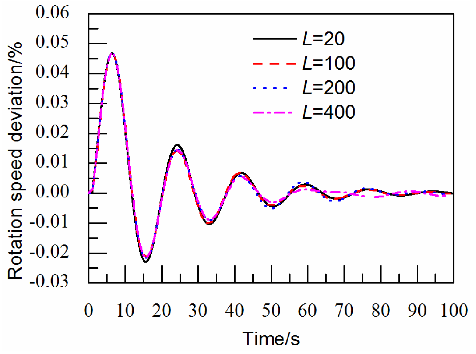
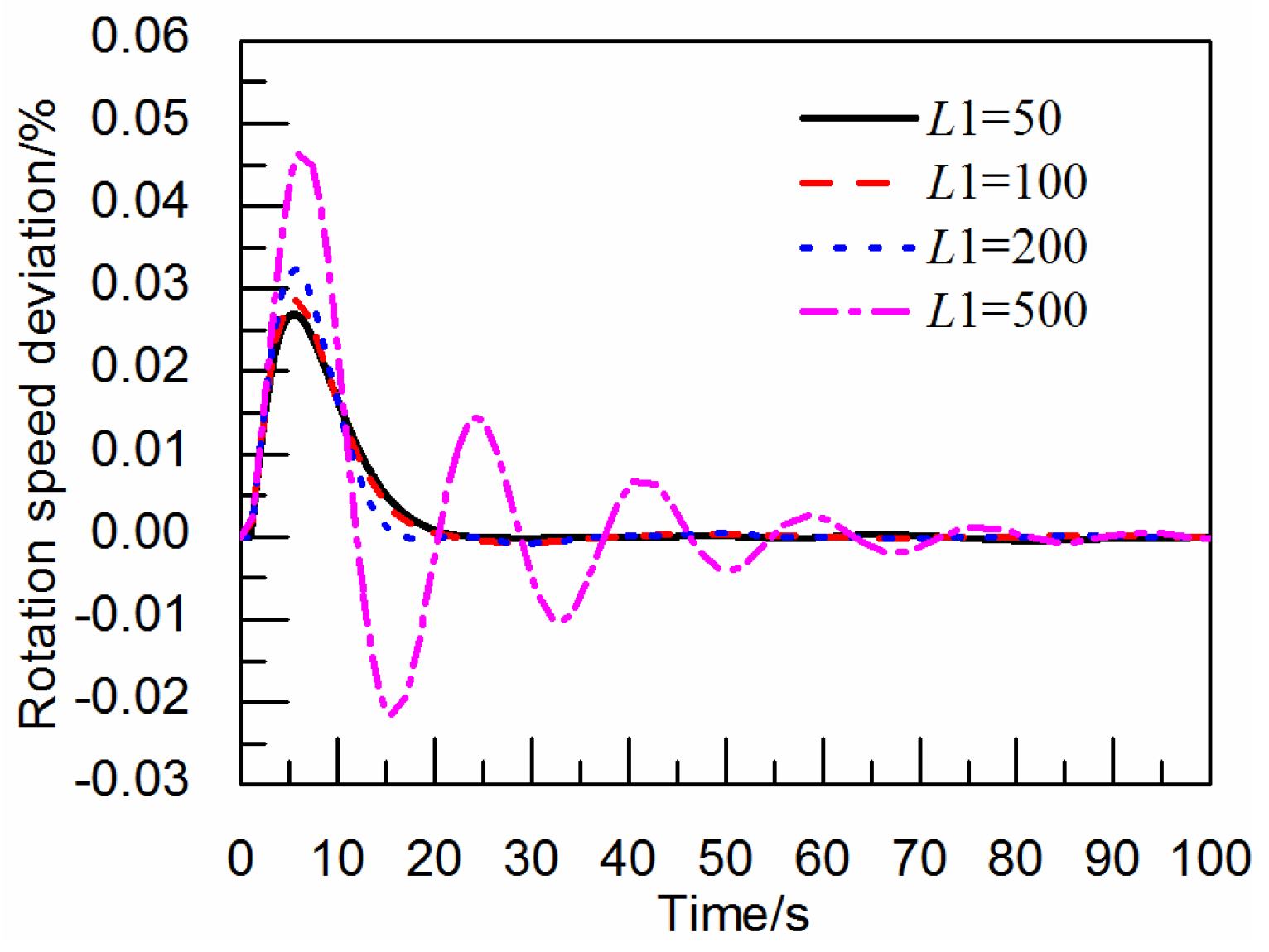
Figure 5 shows the influence of the length of an open channel on the unit rotation speed, when the length of a pressure tailrace tunnel is 500 m, the initial water depth of the open channel is 15 m,
bt = 0.4 and
Td = 6.0 s.
Figure 6 shows the influence of the length on the pressure tailrace tunnel on the basis of unit rotation speed, when the open channel length is 100 m, the initial water depth of the open channel is 15 m,
bt = 0.4 and
Td = 6.0 s.
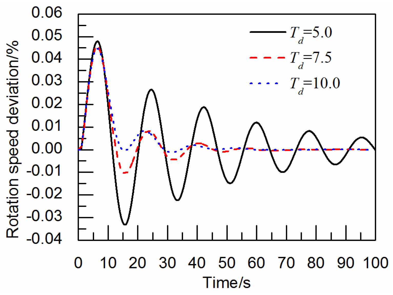
Figure 7 shows the influence of the governing parameter
Td on the unit rotation speed, when the length of the pressure tailrace tunnel is 500 m, the open channel length is 100 m, the initial water depth of the open channel is 15 m and
bt = 0.4.
The wave speed of water hammer in the pressurized conduit may be much faster than that of the wave speed under gravity in the open channel, when there is no surge tank in the tailrace system and the pressurized conduit directly joins the open channel. The fluctuation in the water level in the open channel may not exert substantial influence on the stability of the hydro-turbine governing system. As shown in
Figure 5, the influence of the length variation of the open channel and the fluctuation of the unit rotation speed is small. For the influence of the pressure tailrace tunnel length on the unit rotation speed, as indicated in
Figure 6, the shorter the pressure tailrace tunnel length is, the smaller the water flow inertia time constant would be; the faster the rotation speed attenuation, the better the regulation quality. Then, as shown in
Figure 7, the larger the governor parameters are, the easier the governing system will be operated under stable conditions. Keeping this in view, the regulation quality of the governing system depends on the tailrace tunnel length and the governor parameters, when the tailrace system has an open channel but no surge tank, and, when the influence of the water level fluctuation in an open channel is weak.
Figure 5.
The influence of an open channel length (m) on the unit rotation speed.
Figure 5.
The influence of an open channel length (m) on the unit rotation speed.
Figure 6.
The influence of a pressure flow length (m) on the unit rotation speed.
Figure 6.
The influence of a pressure flow length (m) on the unit rotation speed.
Figure 7.
The influence of Td (s) on the unit rotation speed.
Figure 7.
The influence of Td (s) on the unit rotation speed.
3.3. Simulation with a Tailrace Surge Tank
In the case of the tailrace system having a surge tank, the period of mass waves in the surge tank is the same order of magnitude as the period of gravity waves in the open channel. The fluctuation of water level in the open channel has a noticeable effect on the surge level fluctuations in the surge tank. Next, the fluctuating process of the unit rotation-trailing wave is affected by the level fluctuation in the surge tank, and the period of these two fluctuations are fairly close to each other. Therefore, the effect of the rotation speed on the regulation quality can be analyzed in an indirect way by analyzing the effects of relevant parameters on the wave surge in the surge tank.
Basic parameters of the earlier described example are principally the same, except that a tailrace surge tank has been introduced in front of the pressurized conduit.
3.3.1. The Influence of the Length Variation of an Open Channel on the Regulation Quality
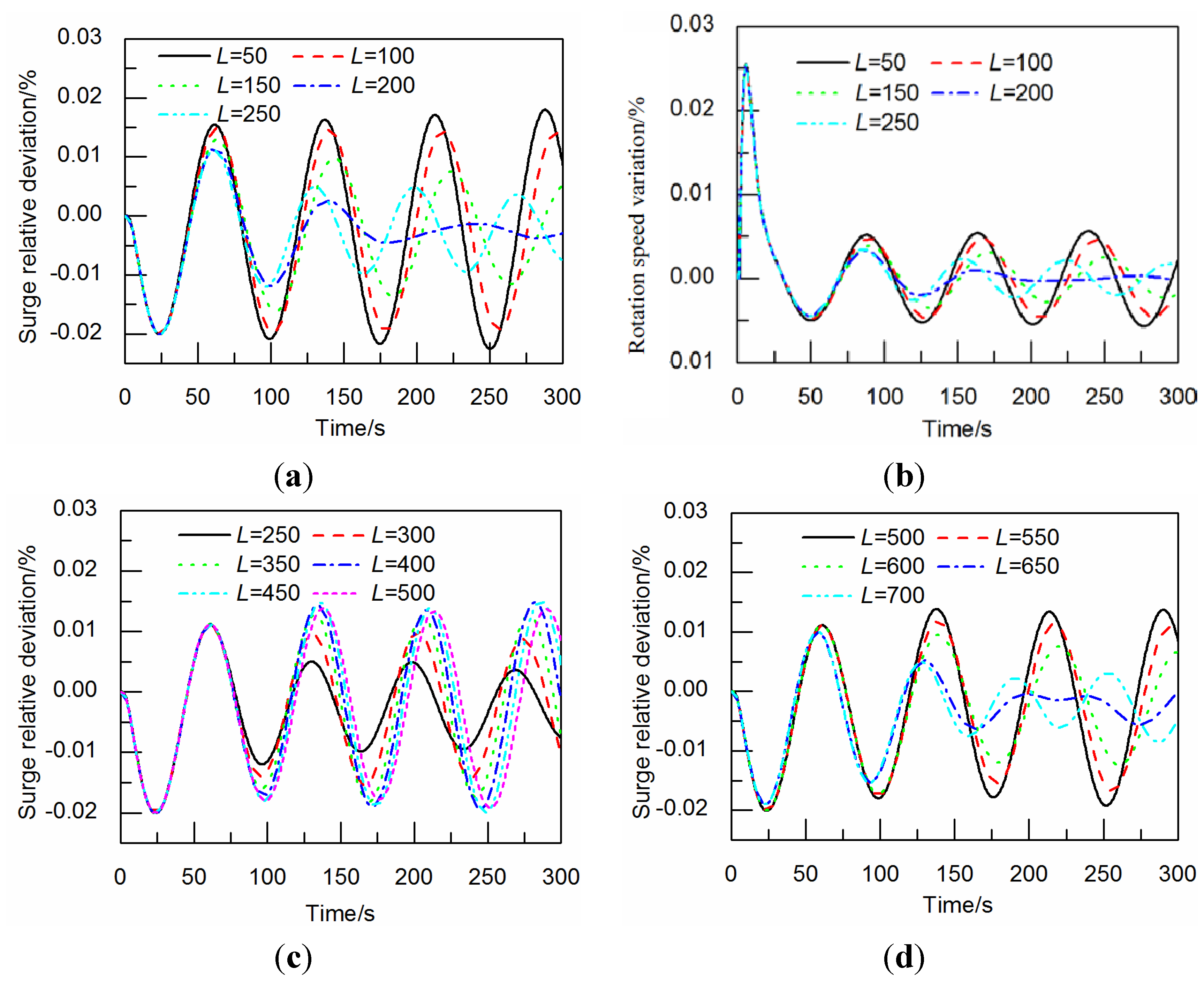
Figure 8 and
Figure 9 show the influence of the length variation of an open channel on the fluctuations of surge level in a surge tank. In this regard, the following two aspects are important: (1) the influences of the length variation of the open channel on the amplitude and period of the surge level fluctuation in the surge tank reflect certain stage periodicity. In some specific lengths of the open channel, water level fluctuation in the open channel would noticeably affect the surge level fluctuation in the surge tank, the waveforms of the surge level fluctuation in the surge tank would show a non-sinusoidal feature, and these specific lengths (shown in the following examples) often turn out to be turning points of the level amplitude variation in the surge tank. For instance, when the length of the open channel increases gradually from 50 m to 200 m, the period of the surge level fluctuation in the surge tank get longer while its amplitude reduces. When the length of the open channel increases gradually from 250 m to 450 m, the period of the surge level fluctuation in the surge tank get longer. When the length of the open channel increases gradually from 500 m to 700 m, the period of the surge level fluctuation in the surge tank get longer while its amplitude reduces. It is pertinent to note that with the increase of the length of the open channel, the period of the surge level fluctuation in the surge tank grows in a periodical manner, not in a persistent way. For example, when the open channel length is 200 m, the surge level fluctuation period in the surge tank may be larger than that of the 250 m long open channel. (2) Because of the stage periodicity of the influence of an open channel length on the surge level fluctuation in the surge tank, it may either attenuate or intensify alternately when the open channel length increases. This suggests the complexity of the influence of an open channel length on the regulation quality.
3.3.2. The Influence of the Open Channel Water Depth on the Regulation Quality
The water depth in the open channel is pertinent for the propagation speed of the gravity wave and is influenced by the surge level fluctuation in the surge tank.
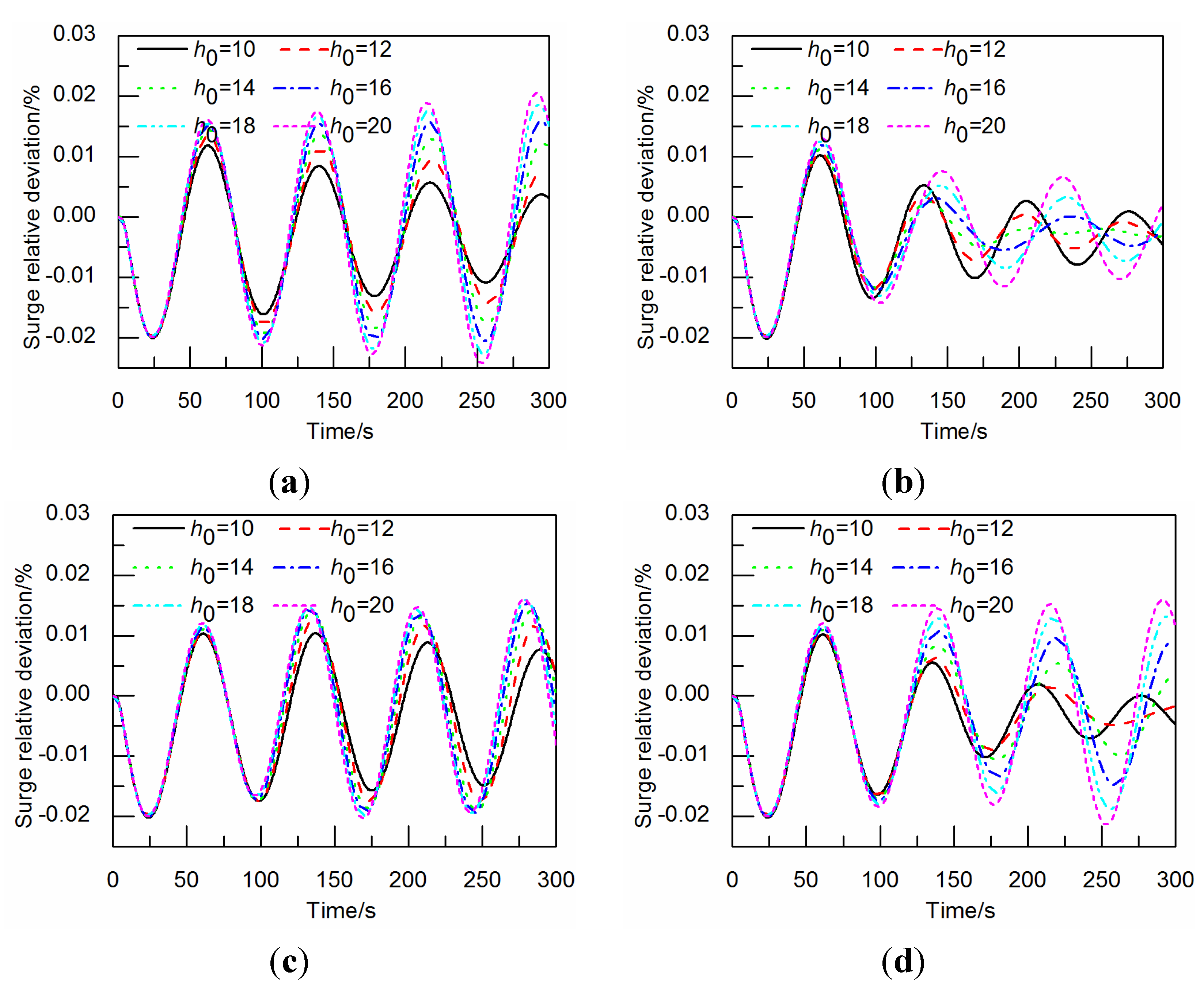
Figure 10 shows the influence of initial water depth on the surge level fluctuation under the different channel lengths. Within a possible range of variation (
i.e., 10–20 m, because the shallow water equations used in the formulations is reasonable for that variation range of the water depth in the open channel, as the velocity is only 1.385 m/s when the water depth is 20 m) for the water depth, the amplitude of surge level fluctuation in the surge tank may increase gradually along with the deepening of the initial water depth in the open channel.
The influence of the water depth in the open channel on the regulation quality is noticeable, which can be represented in the following ways: (1) When the surge tank area and the open channel length are definite, with the increase of water depth in the open channel, the regulation quality gets worse and the surge level fluctuation in the surge tank may take on a gradual transition trend from attenuation to intensification, as shown in
Figure 10. (2) Some specific open channel lengths can still guarantee the hydro-turbine governing system has a sound regulation quality. For instance, when the open channel length is 200 m, as shown in
Figure 10b, even if the initial water depth in the open channel rises to 20 m, the surge level in the surge tank still shows an attenuating trend.
Figure 8.
The influence of an open channel length (m) on surge and rotation speed: (a) surge variation, when open channel length (L) is ranged between 50 m and 250 m; (b) rotation speed variation, when open channel (L) is ranged between 50 m and 250 m; (c) surge variation, when open channel length (L) is ranged between 250 m and 500 m; (d) surge variation, when open channel (L) is ranged between 500 m and 700 m.
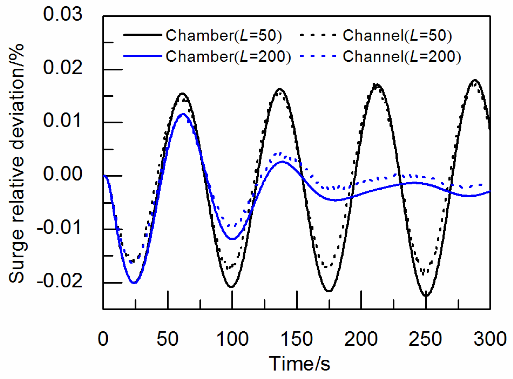
Figure 9.
Comparison of surge waves at surge tank and at open channel head.
Figure 9.
Comparison of surge waves at surge tank and at open channel head.
Figure 10.
The influence of water depth in the open channel on the regulation quality: (a) L = 100 m; (b) L = 200 m; (c) L = 400 m; (d) L = 600 m.
Figure 10.
The influence of water depth in the open channel on the regulation quality: (a) L = 100 m; (b) L = 200 m; (c) L = 400 m; (d) L = 600 m.
3.3.3. Influence of the Surge Tank Area on the Regulation Quality
The initial water depth in the open channel is maintained at 15 m, and the surge tank area increases from 300 m
2 to 500 m
2. With the increase of the surge tank area, the surge level fluctuation attenuation gradually accelerates, the period gradually becomes longer, and the regulation quality gradually gets better. Besides considering the open channel length variation, the increase of surge tank area will also affect the improvement of regulation quality. As shown in
Figure 11, when the open channel length values 100 m and 400 m, respectively, with the increase of surge tank area, the waving shapes (mainly mean the amplitude of the wave) in the surge tank show an attenuation tendency from intensification. When the open channel length values 200 m, the waving shapes in the surge tank attenuate quickly, and the fluctuation overlapping shows favorable effects on the regulation quality.
3.3.4. The influence of Considering an Open Channel or not on the Regulation Quality
When the water depth in the open channel values 15 m,
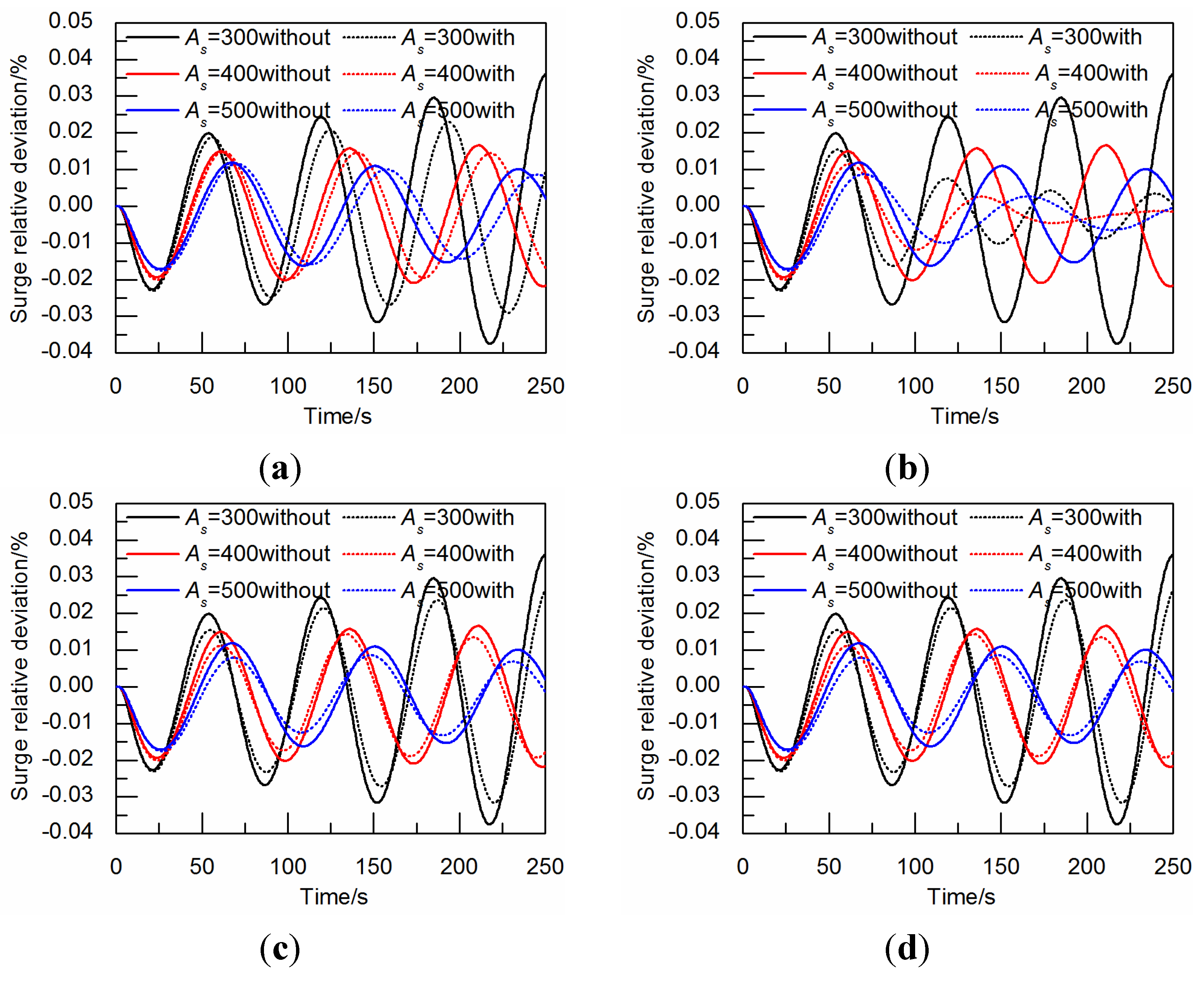
Figure 12 shows the influences of considering an open channel or not on the regulation quality: (1) When the surge tank area is variable, the consideration of the open channel has a favorable influence on the regulation quality; and (2) when the open channel length is variable, the regulation quality becomes better if the open channel effect is considered. However, in some specific channel lengths, such as
Figure 12b, when the open channel length is 200 m, the regulation quality of hydro-turbine governing system with an open channel is obviously superior to that without an open channel.
Figure 11.
The influence of surge tank area on the regulation quality: (a) L = 100 m; (b) L = 200 m; (c) L = 400 m; (d) L = 600 m.
Figure 11.
The influence of surge tank area on the regulation quality: (a) L = 100 m; (b) L = 200 m; (c) L = 400 m; (d) L = 600 m.
Figure 12.
The influence of considering an open channel or not on the regulation quality: (a) L = 100 m; (b) L = 200 m; (c) L = 400 m; (d) L = 600 m.
Figure 12.
The influence of considering an open channel or not on the regulation quality: (a) L = 100 m; (b) L = 200 m; (c) L = 400 m; (d) L = 600 m.
4. Conclusions
By using SSM, a novel elastic water hammer model is developed along with other models of hydro-turbine governing system for the case of the tailrace system with an open channel. Then, a numerical model for load disturbance transient process is established. Finally, according to the complete model, the regulation quality for hydro-turbine governing system with an open tailrace channel under load disturbance is studied, and the effects of open tailrace channel and tailrace surge tank on regulation quality are analyzed. The major conclusions are summarized as follows:
(1) The SSM can reliably be applied to the computation and analysis for the regulation quality of hydro-turbine governing system with an open tailrace channel under load fluctuation.
(2) For the case of a hydropower station without tailrace surge tank, the influence of the open tailrace channel on the regulating quality of hydro-turbine governing system under disturbance can be neglected.
(3) Under load disturbance, the open tailrace channel influences the regulating quality of hydro-turbine governing system by affecting the surge level fluctuation in the surge tank, and its length is a dominant factor. The regulation quality of hydro-turbine governing system can be improved by considering the influence of the water level fluctuation in the open channel.
In future work, this model and method should be improved to be applied for a greater range of the operating conditions, such as load rejection, unit starting up, load adjustment, and frequency adjustment.

