1. Introduction
The doubly fed induction generator (DFIG) is one of the most popular types of generators used in large scale wind turbines with several advantages compared to other wind turbine generators (WTGs) [
1]. However, because the stator windings are directly connected to the grid, DFIG WTGs are quite sensitive to grid disturbances. In the past, WTGs were allowed to disconnect from the grid during low voltage conditions. However, with the rapidly increased penetration of wind power and concentrated wind power installation, disconnection of WTGs due to low voltage conditions can cause serious problems on the power system stability. After the low voltage fault is cleared, high voltage conditions may be induced if there is no fast automatic control of the reactive power, and more wind turbines will be tripped due to the high voltage conditions. Many grid codes require wind power plants (WPPs) to remain connected to the grid during low or high voltage conditions, referred to as low voltage ride through (LVRT) or high voltage ride through (HVRT) requirements [
2,
3].
In recent studies, the characteristics of voltage sags at the point of common coupling (PCC) of WPPs are studied with consideration of grid-angel jumps [
4,
5,
6,
7]. In [
6,
7], the effects of phase-angel jump on transient DFIG operation are discussed, and it is shown that large phase-angel jumps have significant impacts on DFIG transient behaviour. These studies are based on the voltage divider model with different
X/
R ratios of impedance and the detailed discussion is focused on the amplitude of the fault voltage and grid-fault angel. However, the overvoltage conditions during the voltage recovery period have not been investigated.
The transient behaviour of DFIG WTGs under grid fault conditions has been comprehensively investigated by analysing the transient electromagnetic force characteristic of stator flux [
8,
9,
10,
11,
12], and the oscillating response of the DC link voltage was studied in [
13,
14]. Many solutions have been proposed to solve the LVRT problem for DFIGs, which can be categorized into two types including “the crowbar protection method” and “the demagnetizing method”. An additional hardware crowbar circuit with resistors can protect the rotor side converter (RSC) from rotor overcurrent [
15,
16,
17]. A similar circuit called ‘DC-chopper’ is used to protect the DC link from overvoltage [
18,
19]. However, the existing methods have not considered the voltage swell faults under phase-angel jump conditions. In addition to the hardware solutions, many control strategies have been developed for improving the transient response performance of DFIG WTGs under grid voltage sags [
20,
21,
22]. However, most methods have not considered that the converter capacity limitations can influence the DC-overvoltage especially for HVRT and are difficult to implement without considering the phase-angel jump.
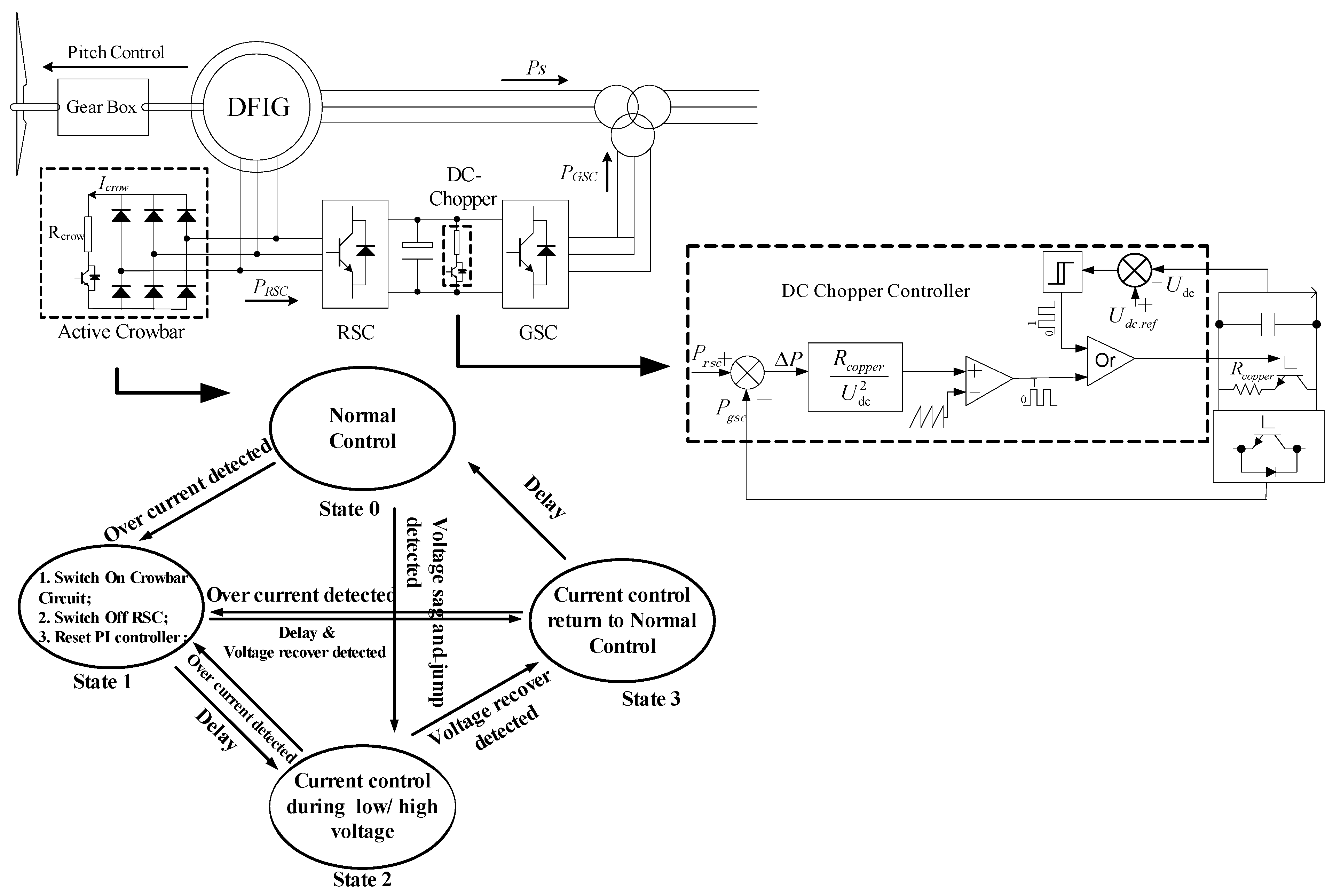
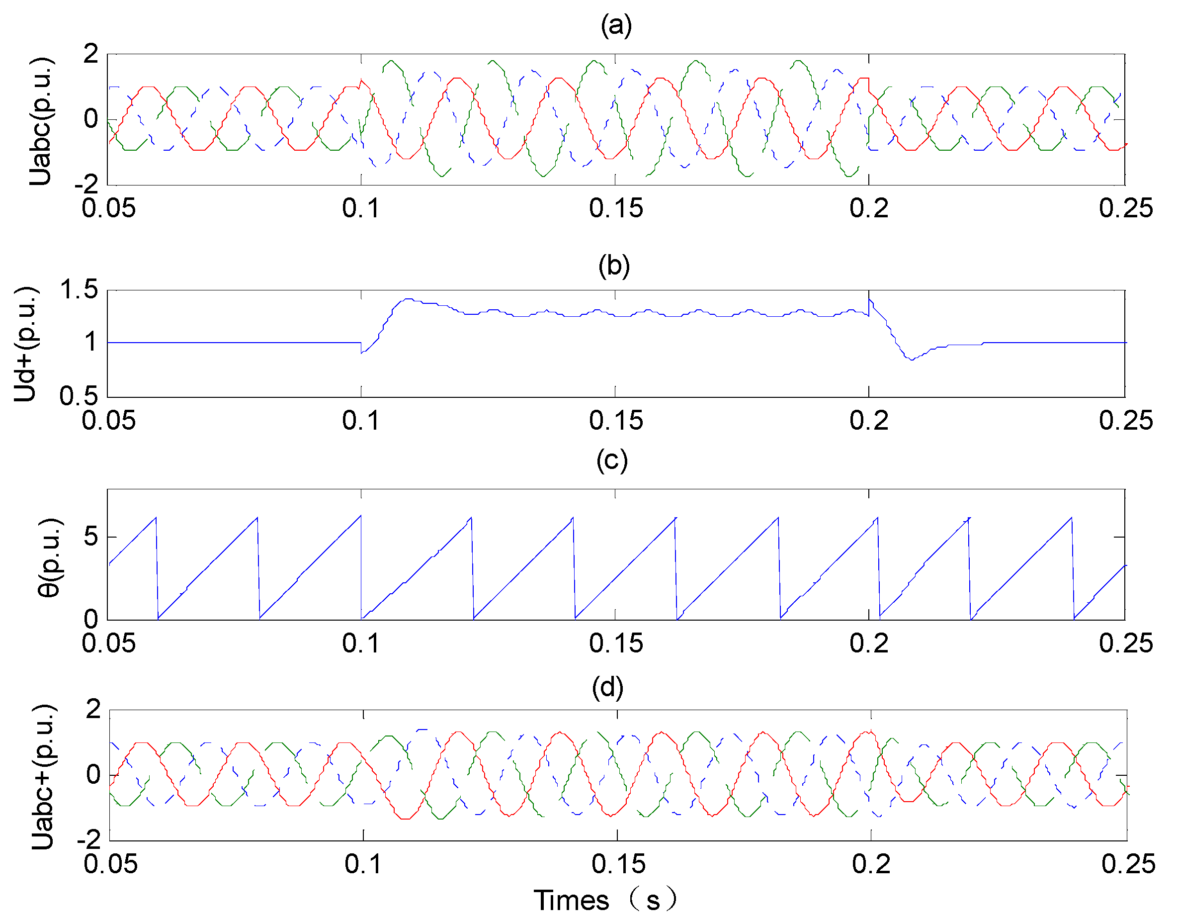
This paper aims to further analyse the transient response of DFIG WTGs with consideration of phase-angel jumps under both grid voltage sags and swells. A rotor crowbar protection scheme used for voltages sag or swell is developed, and a new DC chopper protection scheme coordinated with the active power of the RSC and grid side converter (GSC) is proposed, which can prevent DC links from overvoltage and voltage oscillation. A voltage assessment method considering phase-angel jumps is used in this paper, and the amplitude of the fault voltage and the phase angel for vector control of converters can be obtained correctly. The transient stator flux compensation component is used as feed-forward factor for the vector control, which can improve the transient performance of the RSC controller. In order to keep the DC voltage under the maximum threshold during the grid voltage swell, a reactive current control scheme of the GSC is proposed in this paper. Case studies using Matlab-Simulink (The MathWorks, Natick, MA, USA) have been conducted in order to verify the effectiveness of the proposed protection schemes and control strategies.
The paper is organized as follows: the analysis of the grid fault conditions is described in
Section 2. The behavior of the DFIG WTG and GSC under voltage sag and swell conditions is discussed in
Section 3. The protection schemes of DFIGs for fault ride through (FRT) are explained in
Section 4 and the enhanced GSC and RSC control of DFIGs is presented in
Section 5. The case studies are described and discussed in
Section 6. Finally, the conclusions are drawn.
2. Analysis of Grid Fault Conditions
This section analyzes both grid voltage sag and swell fault conditions at the point of common coupling (PCC) of a wind farm. The voltage-divider model is widely used in the analysis of characteristics of grid faults in radial systems [
4,
5,
6,
7] and is used for the grid voltage sag and swell fault conditions at the PCC of a wind farm.
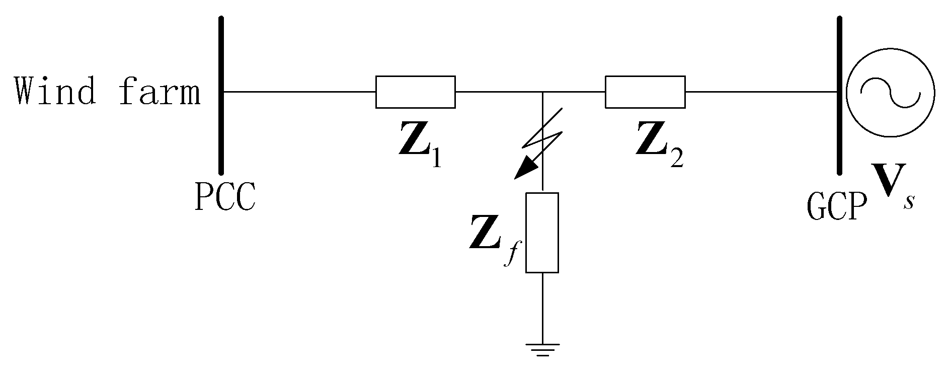
Figure 1 shows the voltage-divider model with the impedance between the wind farm and the fault location where
Vs is the pre-fault voltage,
Z1 is the impedance between the wind farm and the fault location,
Z2 is the impedance between the grid connection point (GCP) and the fault location, and
Zf is the impedance between the fault location and ground. In the voltage-divider model, the wind farm current before as well as during the fault is neglected [
4]. The voltage at the PCC during grid faults can then be defined as:
where
Vsag is the voltage at the PCC during the fault.
Figure 1.
Voltage-divider model.
Figure 1.
Voltage-divider model.
The sum of
Z1 and
Z2 is the equivalent impedance of the external grid and can be defined as
Zs which can be expressed as:
where α
s is the impedance angel of
Zs, and
S is the installed capacity of the wind farm, and
k is the ratio of the system strength to the wind farm installed capacity. Define
p as the ratio of the distance between the fault location and the PCC to the distance between the PCC and the GCP, and consider
Zs is linear by step on the transmission line,
Z2 can be expressed as:
Similarly, by defining
q as the ratio of
Zf to
Zs, which depends on the fault location,
Zs and
Zf have the following relation:
where α
f is the impedance angel of
Z2, λ represents the relative fault distance, and α is fixed for any given source [
4], such as 0° (the most common value for transmission systems), −20° (typical value for distribution systems), or −60° (the minimum value for wind farms located offshore with submarine alternating current (AC) cables). Using Equations (1) and (4), the voltage at the PCC during grid faults can be obtained as follows:
2.1. Symmetrical Voltage Sag Fault
It is shown from Equation (2) to Equation (5) that
Vsag depends on λ and α. For voltage sags under symmetrical fault conditions (Type A),
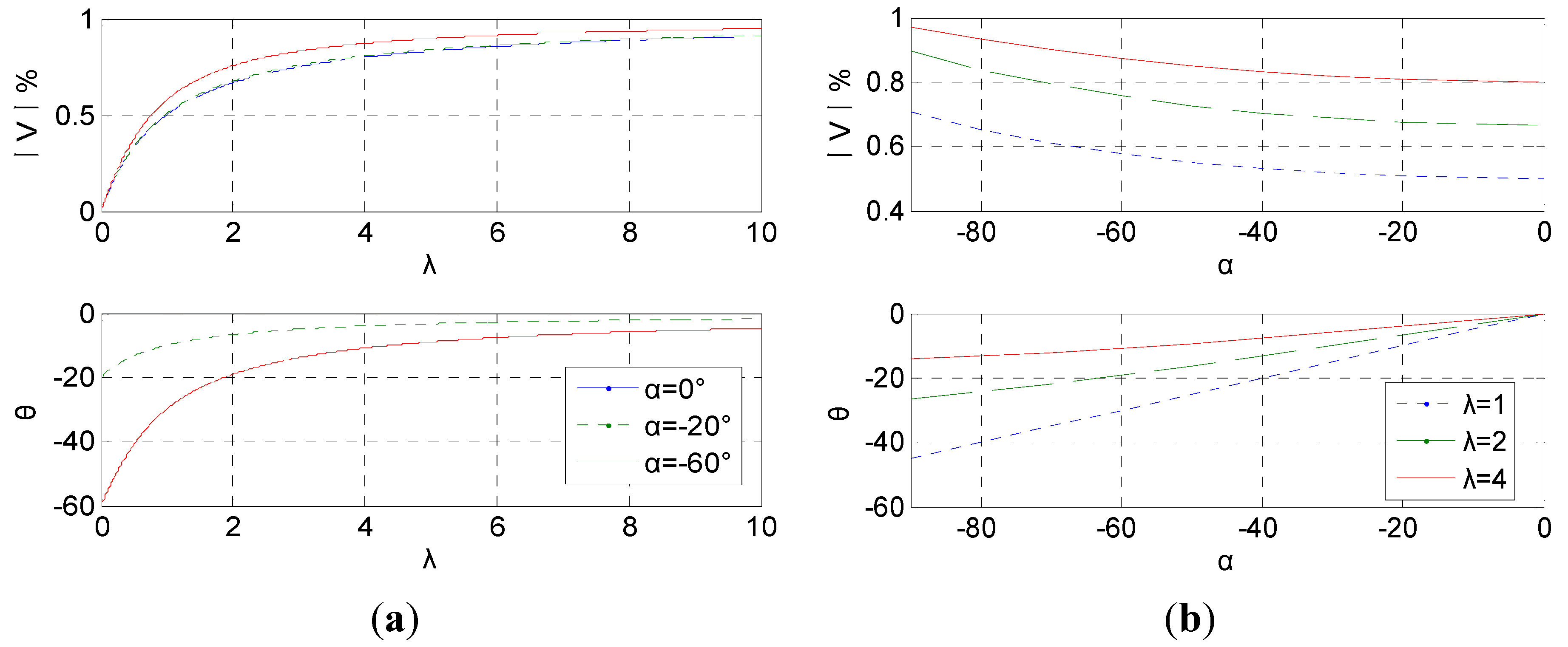
Figure 2 shows the voltage magnitude and phase-angel jump with respect to the change of λ or α.
Figure 2.
Magnitude and phase-angel jump under grid fault Type A. (a) α is fixed; (b) λ is fixed.
Figure 2.
Magnitude and phase-angel jump under grid fault Type A. (a) α is fixed; (b) λ is fixed.
It is shown in
Figure 2a, with the same impedance angel α, both fault depth (1-magnitude of fault voltage) and phase-angel jump decreases as λ increases; it is shown in
Figure 2b, with the same relative fault distance λ, phase-angel jump decreases as |α| decreases (when α = 0°, no phase-angel jump), however, decreasing |α| will increase fault depth.
2.2. Voltage Swell Condition
There are many situations causing voltage swells in the grid, such as load shedding or unbalanced grid faults. According to the analysis of the data from the fault recorders, voltage swells may occur during the low voltage fault recovery period. The cascading wind turbine tripping in China shows that the large scale wind turbine tripping was initially triggered by a low voltage condition caused by an electric component phase to phase fault and quite a number of wind turbines tripped. After the fault was cleared, high voltage condition was induced because there was no automatic control of reactive power compensation within WPPs and more wind turbines tripped due to the over-voltage conditions.
The resulting over-voltage condition may have different magnitudes and durations, depending on the disturbance. Similar to the grid voltage dip analysis results, overshoot of amplitude and phase-angel jump may occur during the voltage recovery, depending on the impedance angel α, the relative fault distance λ, the type and capacity of reactive power compensation equipment.
3. Behavior of DFIG WTG and GSC under Voltage Sag and Swell
This section is to analyze the dynamic responses of the DFIG WTG and GSC under voltage sag and swell conditions, and evaluate the impact on both the RSC and the GSC.
3.1. DFIG Model and GSC Model
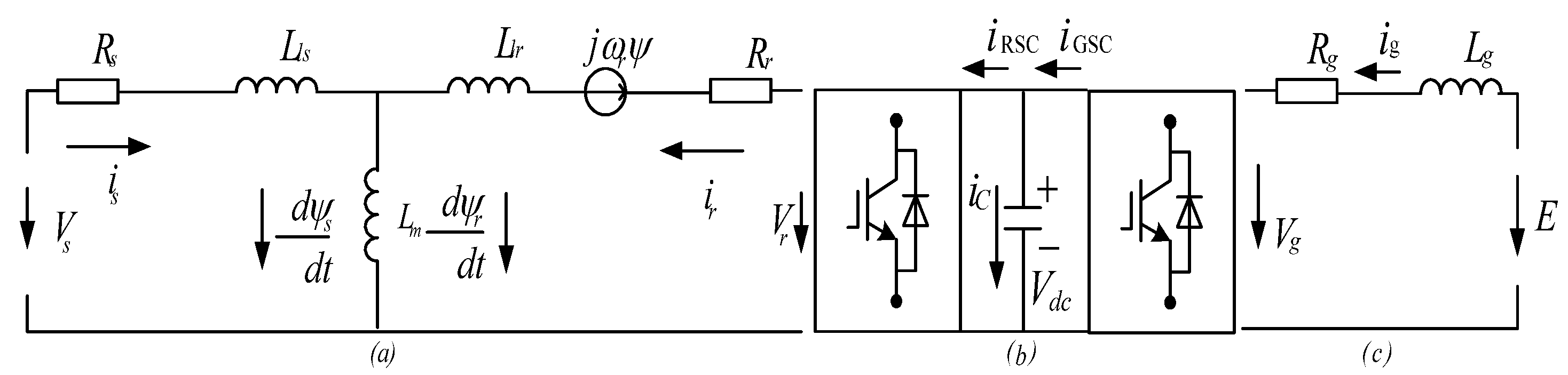
Figure 3a shows the “Γ-form” equivalent circuit of a DFIG following the motor direction. The stator- and rotor-side vectors in the stator reference frame with all the parameters converted to the stator are:
where ω
r is the rotor speed, and subscripts
s and
r indicate stator and rotor.
Figure 3.
Equivalent circuit of: (a) DFIG from the stator side; (b) DC link; and (c) External grid.
Figure 3.
Equivalent circuit of: (a) DFIG from the stator side; (b) DC link; and (c) External grid.
The flux linkage equations of the stator and rotor are:
where
Ls,
Lr and
Lm are the stator inductance, rotor inductance and mutual inductance, respectively.
Using Equations (6) and (7), the rotor voltage vector and the stator flux are obtained as Equations (8) and (9):
where σ = 1 −
Lm2/
Ls·
Lr is the linkage coefficient.
It is shown from Equation (8) that the rotor voltage can be decomposed into two parts (the electromotive force (EMF) and the voltage drop caused by rotor current) [
8].
Figure 3b shows the circuit of DC link. The equation of the DC link voltage is:
Figure 3c shows the grid side equivalent circuit. Neglecting the line side resistance
Rg, the terminal voltage of the GSC is:
where
Lg is the line side inductance of the GSC. In the voltage oriented reference frame, the d- and q-components of the GSC voltage are:
3.2. Behavior of the DFIG WTG under Voltage Sag Condition
Considering the magnitude of the DFIG parameters (about 10
−3), the last part of Equation (9) can be neglected, then Equation (9) is simplified as a first-order differential equation to the stator flux, and the boundary condition is:
where
t0 is the moment when voltage sag or jump occurs. The solution of Equation (9) is obtained as:
where τ =
Ls/
Rs is the time constant of the stator flux, ω
s is the stator angular frequency, and
Vs_
dc is derived by Equation (10), which is a DC component and excited only during the dynamic operation. During normal operation, neglecting the stator resistance, the stator flux can be expressed as follows:
In the analysis, the flux imposed by the stator voltage can be calculated by Equations (11) and (12):
where
P is the depth of the voltage sag or swell, θ is the phase-angel jumps of the voltage.
In
Figure 4a,b, it is shown that the dynamic response of the DFIG and the DC link voltage is independent of the voltage phase when faults occur. With the phase-angel jump increasing, the overshoots of the rotor flux and the rotor current increases, as
Figure 4c shows. By solving Equations (8) and (16), the rotor voltage in the rotor frame is:
Where
![Energies 07 04140 i019]()
is the EMF part:
Figure 4.
Simulation results for three-phase faults (0.5 p.u.) with different voltage phase when faults occur and phase-angel jumps (a) phase angel jump θ = 0°, ωt = kπ; (b) phase angel jump θ = 0°, ωt = (k + 0.25)π; and (c) phase angel jump θ = 60°, ωt = kπ.
Figure 4.
Simulation results for three-phase faults (0.5 p.u.) with different voltage phase when faults occur and phase-angel jumps (a) phase angel jump θ = 0°, ωt = kπ; (b) phase angel jump θ = 0°, ωt = (k + 0.25)π; and (c) phase angel jump θ = 60°, ωt = kπ.
Under a severe situation (P = 1, θ = 0), for example, before and after the fault occurs, the aptitude of Vr0 changes from [Lm·Vs·|s|/Ls] to [Lm·(1−s)·Vs/Ls] according to Equation (18). Assuming s = 0.3, the overvoltage value of Vr0 is 2.3 times of the nominal value, and it is 4.3 times assuming s = −0.3. The results show that when grid faults occur, a large rotor voltage is required to control the rotor current. Since the performance of the RSC controller is restricted by its capability, the rotor current cannot follow such a reference, which leads to over current, and then the over current protection of the RSC is activated. Since the active power output of the GSC is substantially reduced after a grid fault, a large quantity of energy from the RSC flows into the DC link which causes the DC voltage to increase and oscillate.
3.3. Behavior of the DFIG WTG under Voltage Swell Conditions
Figure 5 shows the simulation results considering the voltage magnitude and the phase-angel jump during the grid fault recovery. It is shown that the operating characteristics of the DFIG WTG under voltage swells are similar to those under voltage sags. However, after the transient oscillation, the DC voltage increases up to a high value because the line side voltage exceeds the maximum voltage of the GSC, which is:
where
M is the maximum voltage utilization. The minimum value of
vdc is determined by
M and |
vglms| (
M =
![Energies 07 04140 i030]()
for SVPWM; =
![Energies 07 04140 i031]()
for SPWM; and = 1.35 for diode rectification, which is the minimum limitation). Based on Equation (19), the minimum DC voltage value increases with the high grid voltage, which may exceed the maximum controllable DC voltage range of the GSC, and lead to continuous overvoltage of the DC link during the whole process of the high voltage condition.
Figure 5.
Simulation results for three-phase faults (1.3 p.u.) with different voltage phases when faults and phase-angel jump occur (a) phase angel jump θ = 0°, ωt = kπ; (b) phase angel jump θ = 0°, ωt = (k + 0.25)π; and (c) phase angel jump θ = 60°, ωt = kπ.
Figure 5.
Simulation results for three-phase faults (1.3 p.u.) with different voltage phases when faults and phase-angel jump occur (a) phase angel jump θ = 0°, ωt = kπ; (b) phase angel jump θ = 0°, ωt = (k + 0.25)π; and (c) phase angel jump θ = 60°, ωt = kπ.
6. Case Studies
The case studies were carried out with a 1.5-MW DFIG WTG to verify the efficacy of the proposed LVRT and HVRT protection schemes, and the enhanced control methods using Matlab/Simulink Simpower Systems. The parameters of the WTG are listed in the Appendix. The threshold of the rotor current to activate the crowbar protection is 2 p.u., and the threshold of the DC voltage to activate the chopper protection is 1.15 p.u., and 1.05 p.u. to deactivate. Three case studies were conducted and compared. The case study scenarios are listed in
Table 1. For the case studies, a three-phase fault is applied at 2 s with 200 ms duration causing the grid voltage drop of 0.2 p.u. and the voltage swell of 1.3 p.u. during the grid fault recovery (starting at 2.2 s).
Table 1.
Control schemes for case studies.
Table 1.
Control schemes for case studies.
| Case | LVRT and HVRT Protection | LVRT and HVRT Control |
|---|
| 1 | Crowbar disabled DC_Chopper disabled | RSC without enhanced control GSC without enhanced control |
| 2 | Crowbar disabled DC_Chopper disabled | RSC with enhanced control
GSC with enhanced control |
| 3 | Crowbar enabled DC_Chopper enabled | RSC with enhanced control
GSC with enhanced control |
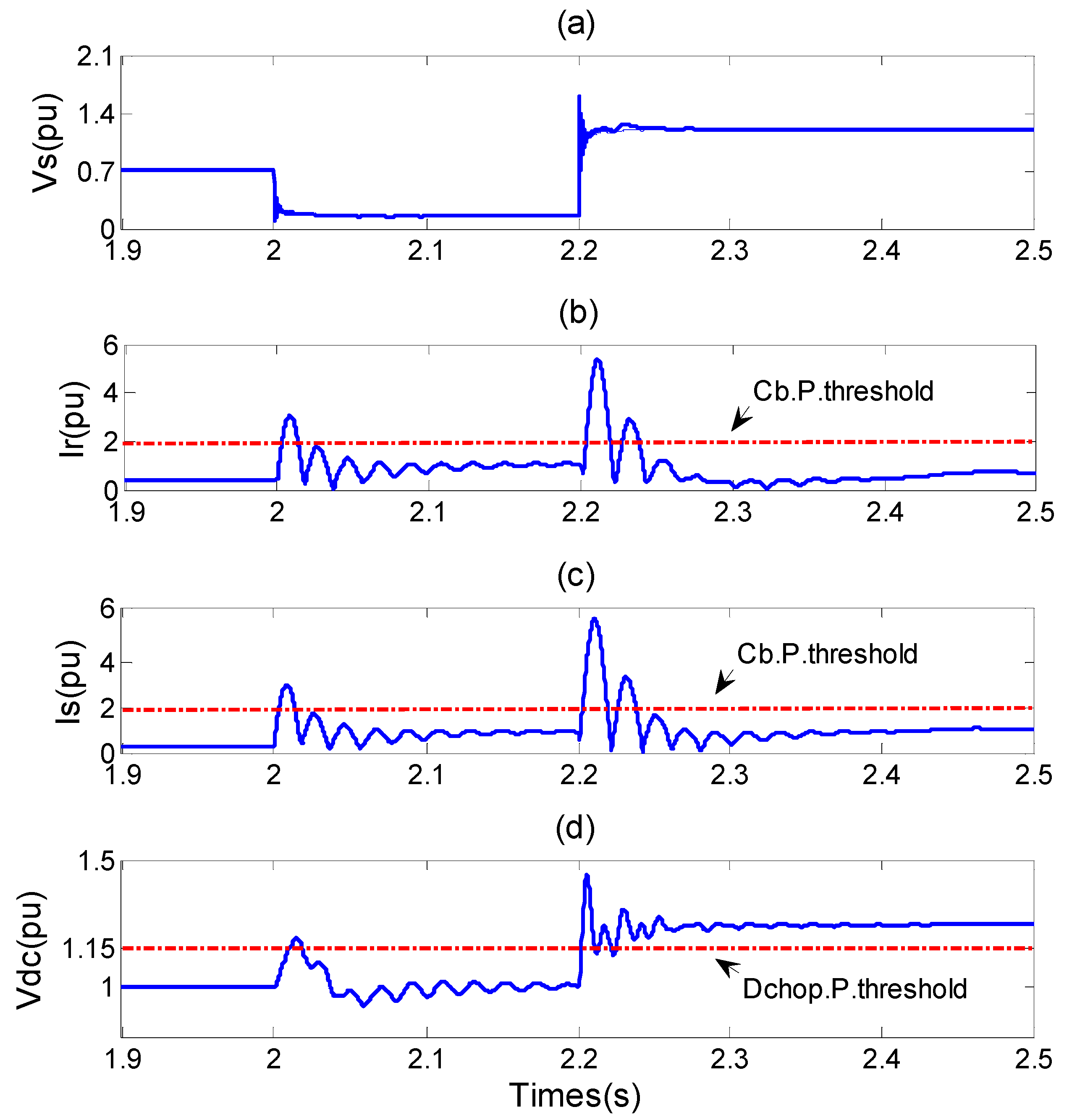
Figure 11 shows the simulation results of Case 1 which does not have the crowbar or the DC chopper protection scheme or the enhanced converter control schemes.
Figure 11a shows the voltage profile of the pre-fault, fault and recovery periods. It is shown in
Figure 11 b,c and d that the rotor current, stator current and the DC link voltage exceeded the protection settings and the WTG would have tripped due to this.
Figure 11.
The responses of the DFIG WTG for case 1: (a) stator voltage; (b) rotor current; (c) stator current; and (d) DC voltage.
Figure 11.
The responses of the DFIG WTG for case 1: (a) stator voltage; (b) rotor current; (c) stator current; and (d) DC voltage.
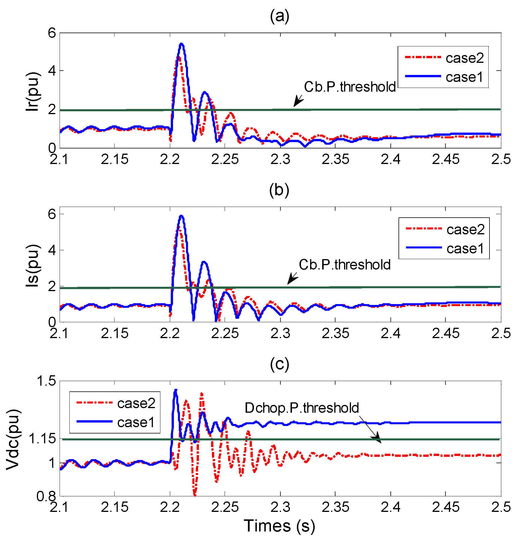
The simulation results of Case 2 are shown in
Figure 12. The comparison results of rotor and stator currents with and without the enhanced RSC and GSC control are shown in
Figure 12a,b. It is shown that the current overshooting has been reduced by the enhanced RSC and GSC control. The DC link voltage with and without the enhanced RSC and GSC control is shown in
Figure 12c and it is shown that the DC link voltage can decrease below the threshold after about 180 ms from the starting point of the recovery. However, the DC link over-voltage is still an issue.
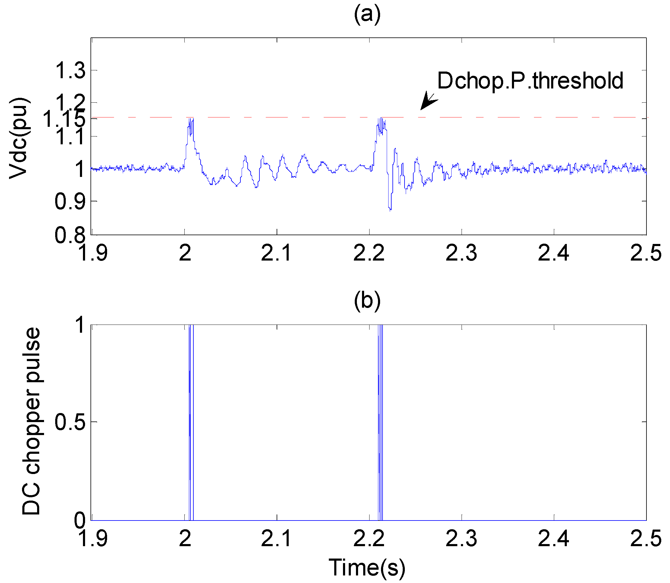
The DC link voltage and the DC chopper pulse of case 3 are shown in
Figure 13. It is shown that the DC link voltage can be kept below the threshold by the combination of the crowbar scheme, and the enhanced RSC and GSC control and the DFIG WTG can successfully ride through the low voltage conditions and the high voltage conditions.
Figure 12.
The responses of the DFIG WTG for case 2. (a) rotor current; (b) stator current; (c) DC voltage.
Figure 12.
The responses of the DFIG WTG for case 2. (a) rotor current; (b) stator current; (c) DC voltage.
Figure 13.
The DC link voltage of case 3: (a) DC voltage; (b) DC chopper circuit control pulses.
Figure 13.
The DC link voltage of case 3: (a) DC voltage; (b) DC chopper circuit control pulses.
7. Conclusions
This paper analyses the transient response of the DFIG WTG with consideration of the phase-angel jump under both grid voltage sag and swell conditions. The rotor crowbar protection scheme coordinated with DC chopper protection scheme is developed to deal with both voltage sag and voltage swell. With the voltage detection method considering the phase-angel jump, the fast coordinated control of the RSC and GSC has been developed. Simulation results show that, by adding the transient stator flux compensation feed-forward factors for the vector control, the transient performance of the RSC controller can be improved. By the reactive current control of the GSC, the DC link voltage can be maintained below the threshold. With the developed crowbar protection scheme, DC chopper protection scheme, and the enhanced RSC and GSC control, the DFIG WTG can successfully ride through the continuous low voltage and high voltage conditions.


 is the EMF part:


 for SVPWM; =
  for SPWM; and = 1.35 for diode rectification, which is the minimum limitation). Based on Equation (19), the minimum DC voltage value increases with the high grid voltage, which may exceed the maximum controllable DC voltage range of the GSC, and lead to continuous overvoltage of the DC link during the whole process of the high voltage condition.

 ), so the positive voltage can be calculated as:


