Development of a Direct Methanol Fuel Cell with Lightweight Disc Type Current Collectors

Abstract
: The direct methanol fuel cell (DMFC) adopts methanol solution as a fuel suitable for low power portable applications. A miniature, lightweight, passive air-breathing design is therefore desired. This paper presents a novel planar disc-type DMFC with multiple cells containing a novel developed lightweight current collector at both the anode and cathode sides. The present lightweight current collector adopts FR4 Glass/Epoxy as the substrate with the current collecting areas located at the corresponding membrane electrolyte assembly (MEA) areas. The current collecting areas are fabricated by sequentially coating a corrosion resistant layer and electrical conduction layer via the thermal evaporation technique. The anode current collector has carved flow channels for fuel transport and production. The cathode current collector has drilled holes for passive air breathing. In order to ensure feasibility in the present concept a 3-cell prototype DMFC module with lightweight disc type current collectors is designed and constructed. Experiments were conducted to measure the cell performance. The results show that the highest cell power output is 54.88 mW·cm−2 and successfully demonstrate the feasibility of this novel design.1. Introduction
The direct methanol fuel cell (DMFC) has many advantages, such as high efficiency, low pollution and noise, easy portability and handling system simplicity and near-room operating temperature. It is specifically suitable for 3C applications. A thin, lightweight DMCF design is desired [1,2]. The current collector/bipolar plate plays a major role for fuel cells in terms of weight, volume and cost. As graphite has superior electrical conductivity and chemical stability, it is widely adopted as the bipolar plate material, but graphite has the disadvantages of being brittle, expensive, difficult to machine and bulky, such that it might limit miniaturization in portable applications. Many researchers are therefore committed to developing current collectors/bipolar plates using new materials, geometry, fabrication, processing materials and methods [3–5].
Conventionally, the DMFC is designed to be serially interconnected via bipolar plates which act simultaneously as the anode on one side and the cathode on the other. The cells are then connected in a front-to-back orientation, forming a stack [3]. In order to shrink the DMFC volume for low power portable applications, a side-by-side configuration that connects the cells in a lateral direction forms a planar type DMFC. This configuration has been intensively explored in recent years as an alternative to the vertical stack. This configuration allows more flexibility in the DMFC design. The main side-by-side configurations are the banded configuration and the flip-flop configuration. In the banded configuration the electrodes overlap. The cathode of one cell is strapped across the membrane electrode assembly (MEA) of the anode of the next adjacent cell. The flip-flop configuration could eliminate the need to cross the MEA via one-side bipolar films allowing the DMFCs to be used in planar array fuel cells [6,7]. Therefore, more varied techniques have been increasingly applied in the development of planar type DMFCs for portable applications.
Printed circuit board (PCB) technology, a mature and well-established mass production process, is used to produce a planar-type fuel cell that could shrink the cell size and integrate the electric circuits more easily into the energy management system [8–10]. In the PCB DMFC the thermal and mechanical properties of the metallic current collectors and the FR4/Epoxy substrate are quite different, sometimes leading to a mismatch of components and assembly difficulties. The related techniques for the microelectromechanical system (MEMS) have also been gradually applied to miniaturize the size of DMFCs. A micro DMFC was developed by Lu et al., via fabricating a silicon wafer with deposited metal layers that could collect and conduct electrons [11]. A type of all-polymer micro-DMFC was proposed by Cha et al., which adopted a UV-sensitive photoresist and applied UV lithography, lift-off and metallization processes [12]. A silicon-based micro-scale DMFC system was presented by Yao et al. [13] This system used a silicon wafer with arrays of etched holes selectively coated with a non-wetting agent to collect cathode water, a silicon membrane micro pump to pump the collected water from the cathode to the anode and a passive liquid-gas separator to remove CO2 bubbles. A MEMS-based DMFC using nano-imprint technology was developed by Zhang et al. [14]. As silicon is brittle, the mechanical strength of the silicon-based micro DMFCs may be low. Adopting silicon as a substrate might restrict micro-DMFC fabrication and assembly due to this fragility. It is important to experiment with different substrate materials and fabrication processes in the development of micro-DMFCs. In the previous paper we proposed a type of lightweight DMFC current collector using FR4/Epoxy substrate with two metal layers, coated using thermal evaporation techniques [15]. Finally, no circular geometric design for portable direct methanol fuel cell (DMFC) modules has been proposed; therefore, in this study, the concept of notebook CD-ROM (Compact Disc Read-Only Memory) devices was referenced to design a module. Because of the current demand for notebooks that are light in weight, the CD-ROM device in some notebooks can be removed. This paper describes how a disc-type DMFC module can be used to replace a CD-ROM device and supply power. To reduce the thickness and weight of notebooks, a microelectromechanical system (MEMS) technique was extended to fabricate DMFC current collectors from a single cell into a disc module featuring multiple cells.
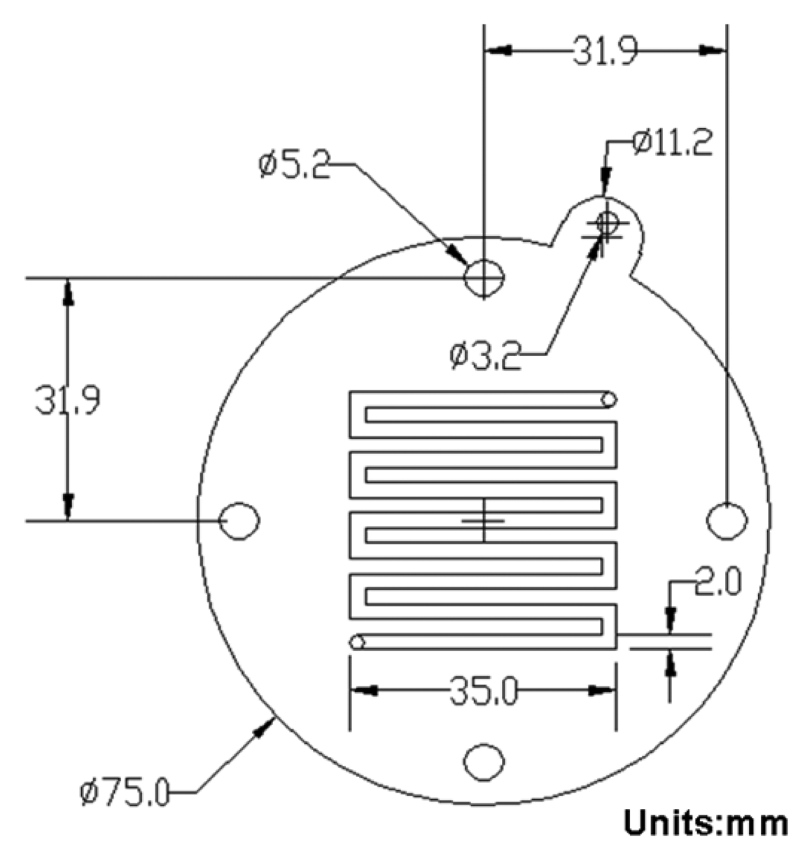
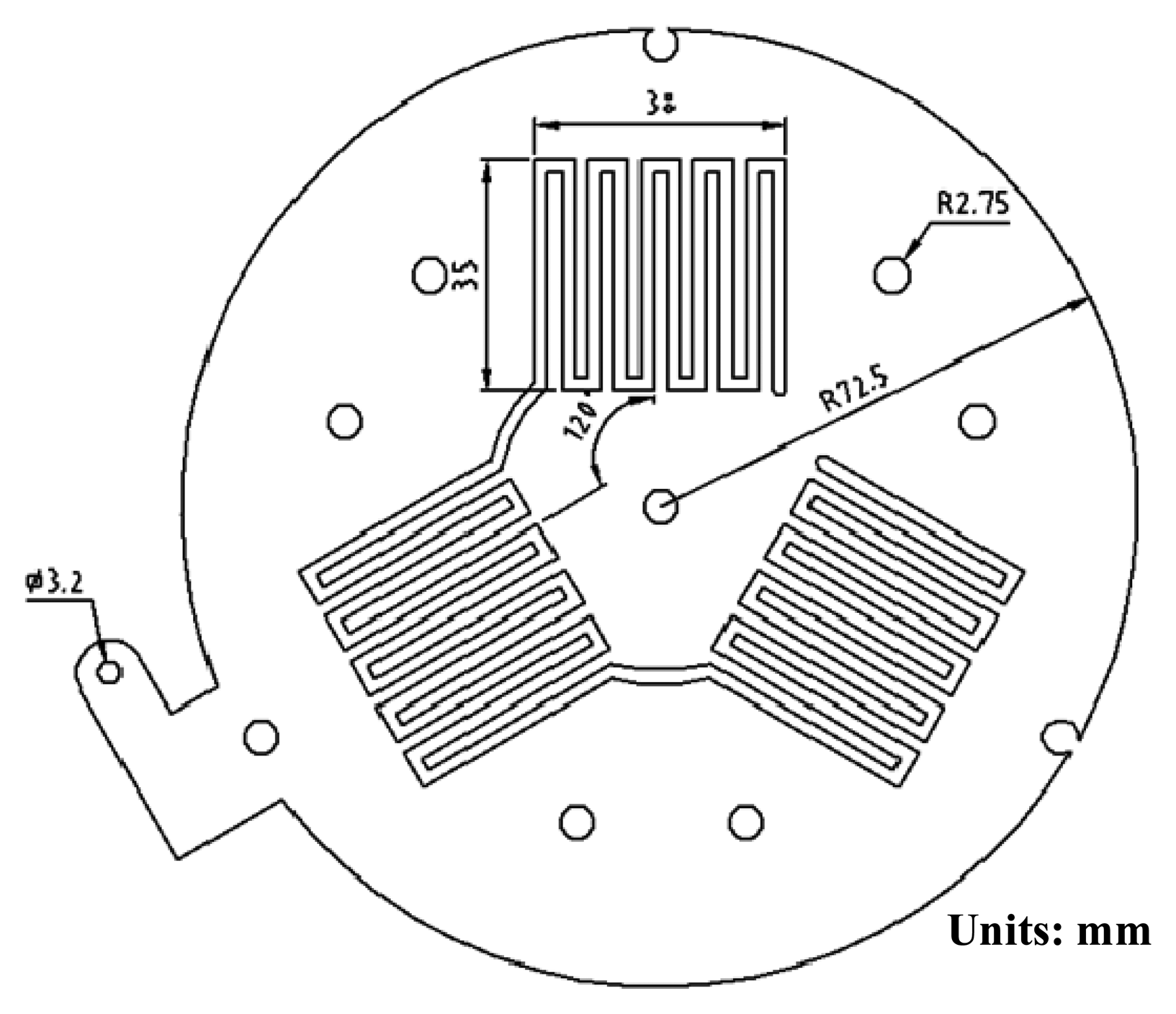
2. Design and Fabrication of Current Collectors
The geometries of the current collectors were drawn using AutoCAD software (Autodesk Inc., San Rafael, CA, USA) and converted into CNC (Computer Numerical Control) code, and the code was sent to a milling machine control box. An FR4/Epoxy plate was placed at the working surface. The outlines, flow channels and holes were carved or drilled using an end milling tool with the path controlled by the CNC code. The MEA was composed of Nafion® 117 (DuPont Fuel Cells, Wilmington, DE, USA) as the electrolyte and carbon cloth for the diffusion layers. The catalyst load at the anode was 1 mg·cm−2 Pt/0.5 mg·cm−2 Ru, and the catalyst load at the cathode side was 1 mg·cm−2 Pt. The reactive area of the MEAs adopted in this paper is 35 mm × 35 mm. The corresponding current collectors were placed around this area. This study began with a single cell to determine the suitable parameter controls for the thermal coating process and then the work was extended to three-cell module fabrication. Figure 1 shows the geometry and key dimensions of a circular single-cell DMFC. Figure 2 shows the geometry and key dimensions of a circular 3-cell DMFC module. Both thicknesses are 2 mm. The geometries of the anode and cathode substrates are the same for either the single-cell or 3-cell DMFC module.
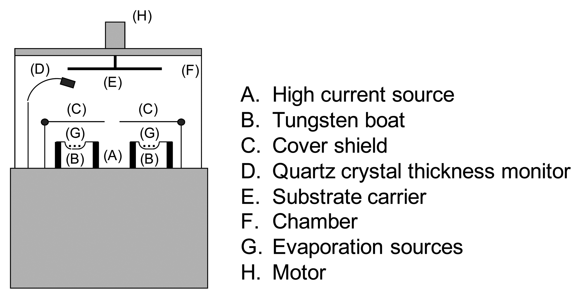
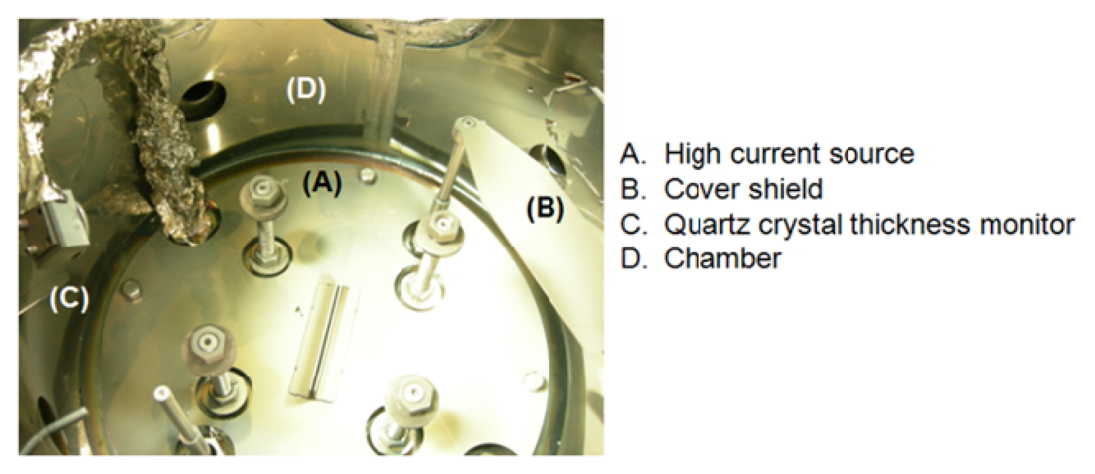
Thermal evaporation is started after the machining process is completed. This is a two-stage process. The first stage involves coating a metal thin film as the electricity conduction layer. The second stage coats a second metal thin film onto the electricity conduction layer as the corrosion resistance layer. A sketch of the thermal evaporation machine is shown in Figure 3. Figure 4 shows the inside of the thermal evaporation machine. FR4/Epoxy substrate is held by the substrate carrier in the top of the chamber. The evaporation sources, metal ingots, are placed in the tungsten boat. The chamber is evacuated to 5 × 10⁻⁵ torr during the thermal evaporation process. The cover shields are originally set to block the metal ingots. The metal ingots are heated by a high current source through the tungsten boat. The metal ingots are gradually vaporized. Once the metal ingots are well vaporized, the cover shields are unblocked from the tungsten boat and the metal vapor is released into the chamber. A metal film is then coated onto the surface of the FR4/Epoxy substrate. A quartz thickness monitor is placed in the chamber to estimate the thickness of the coated metal thin film. When the coated metal thin film reaches the desired thickness, the high current source is cut off and the chamber starts the breaking vacuum stage. The thermal evaporation process is then completed.
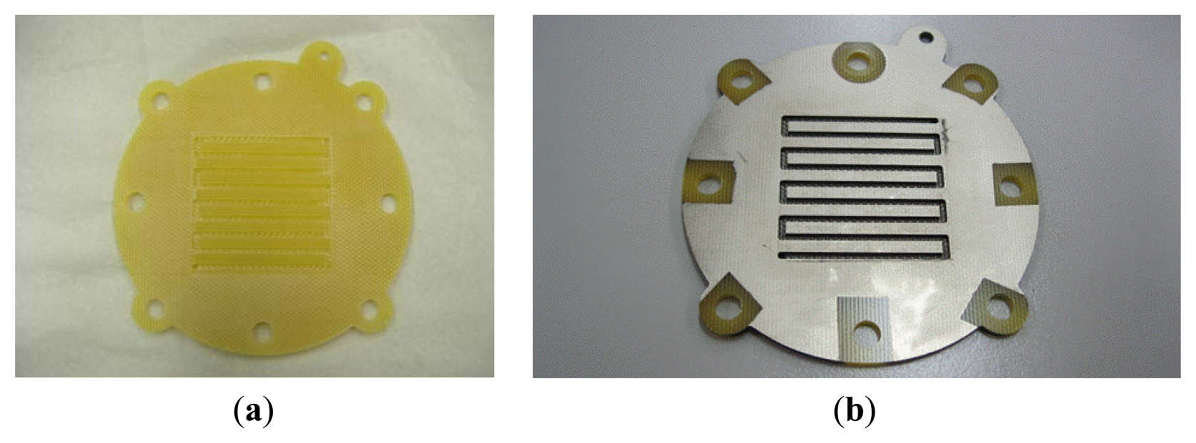
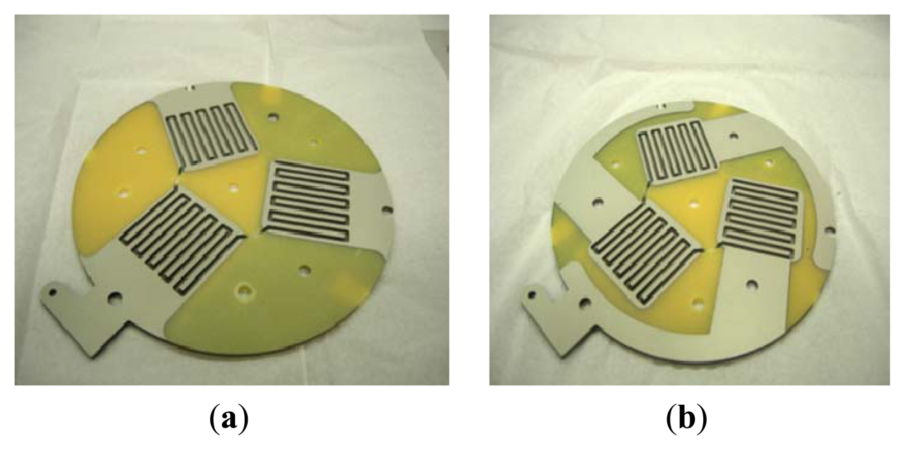
As there are two metal thin films coated onto the substrate surface, each current collector needs to go through the thermal evaporation process twice and different metal ingots are used in each process. The material adopted for the electricity conduction layer is copper. The material adopted for the corrosion resistance layer is nickel. To increase the amount of electricity received from the MEA, the thickness of the copper was greater than that of the nickel because the cost and melting point of copper are lower than those of nickel. Figure 5a shows the completed single-cell current collector is shown in Figure 5b. The completed anode and cathode current collectors for the 3-cell DMFC module are shown in Figure 6a,b, respectively.
3. Disc-Type Direct Methanol Fuel Cell (DMFC) Fabrication
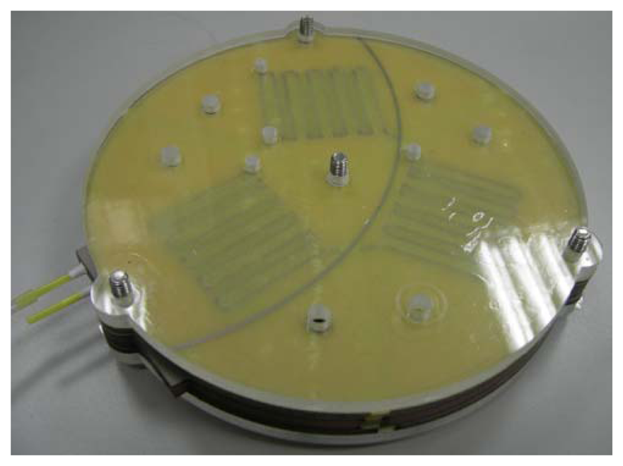
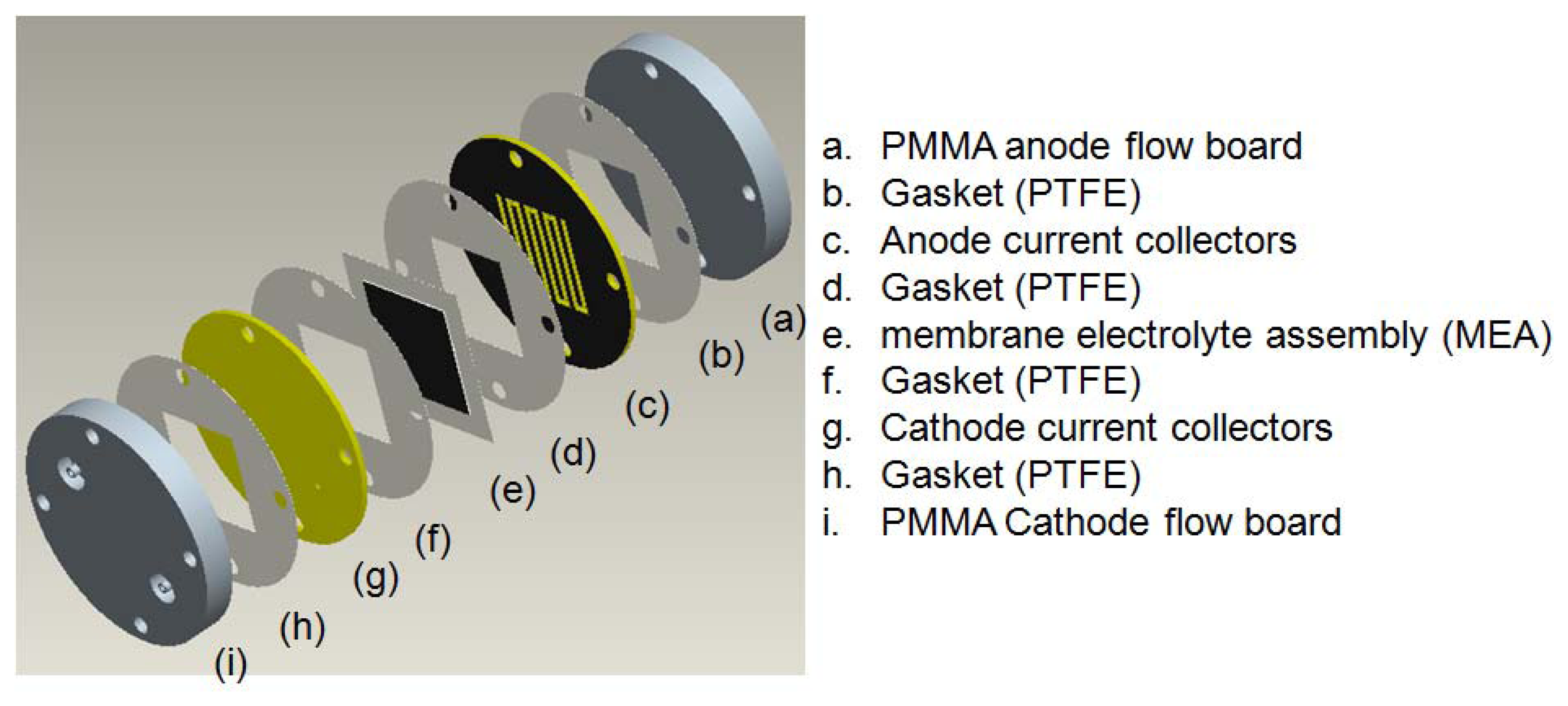
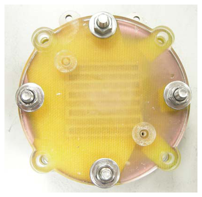
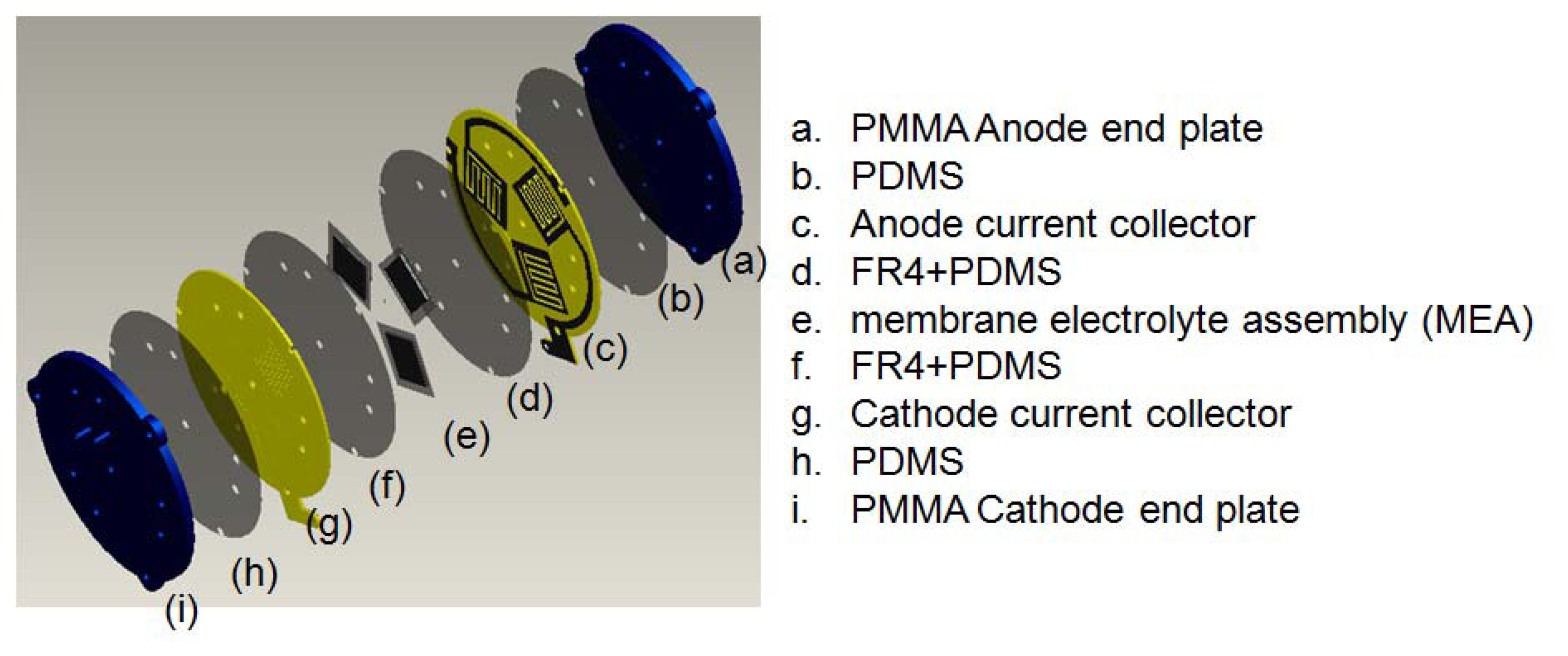
After the DMFC current collector fabrication is completed the next step is to assemble the disc-type DMFC. In order to determine suitable thermal evaporation parameters, first a single-cell DMFC is constructed. An exploded 3D CAD drawing is shown in Figure 7. The anode and cathode current collectors are fabricated using the method described above. The MEA is sandwiched between the anode and cathode current collectors. A gasket made of polydimethylsiloxane (PDMS) coated at the FR4/Epoxy plate is placed between the two layers to prevent leakage. Both anode and cathode end boards are made of polymethylmethacrylate (PMMA) and assembled at the sides of the two ends. All components are screwed together. A picture of the assembled single-cell disc-type DMFC is shown in Figure 8. After the single-cell disc-type DMFC is studied a 3-cell disc-type DMFC module is fabricated. Like the single-cell disc-type DMFC, the exploded 3D CAD drawing of the 3-cell disc-type DMFC module is shown in Figure 9. All components are also screwed together. A picture of the assembled 3-cell disc-type DMFC is shown in Figure 10.
4. Results and Discussion
4.1. Resistance Comparison of the Single-Cell DMFC Current Collector
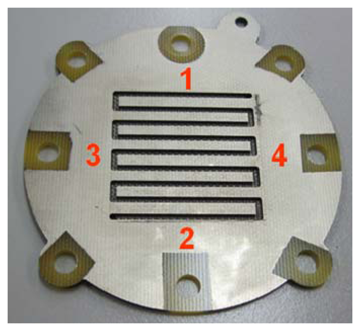
To determine the electrical resistivity of the current collectors of different metal thin film thicknesses made through the thermal evaporation processes, four points were selected and measured for the single-cell DMFC collector. The selected four monitoring points for the single-cell DMFC current collector are shown in Figure 11. The copper thin film thickness, the electricity conduction layer, was set at 15, 20 and 25 KÅ. The nickel thin film thickness, the corrosion resistance layer, was set at 2, 4 and 6 KÅ. The results are shown in Table 1. According to the results, the resistivity is quite low for any combination, with the range from 1.35 to 3.50 mΩ. Compared to the nickel thin film thickness, the copper thin film thickness dominates the effect. If the copper thin film is thicker, the electricity resistivity becomes lower. This is because copper has higher electrical conductivity than nickel. If the copper thin film thickness is increased from 15 to 20 KÅ, the electrical resistivity decreases significantly compared with that from increasing the copper thin film thickness from 20 to 25 KÅ.
4.2. Single-Cell Disc-Type DMFC Performance Comparison
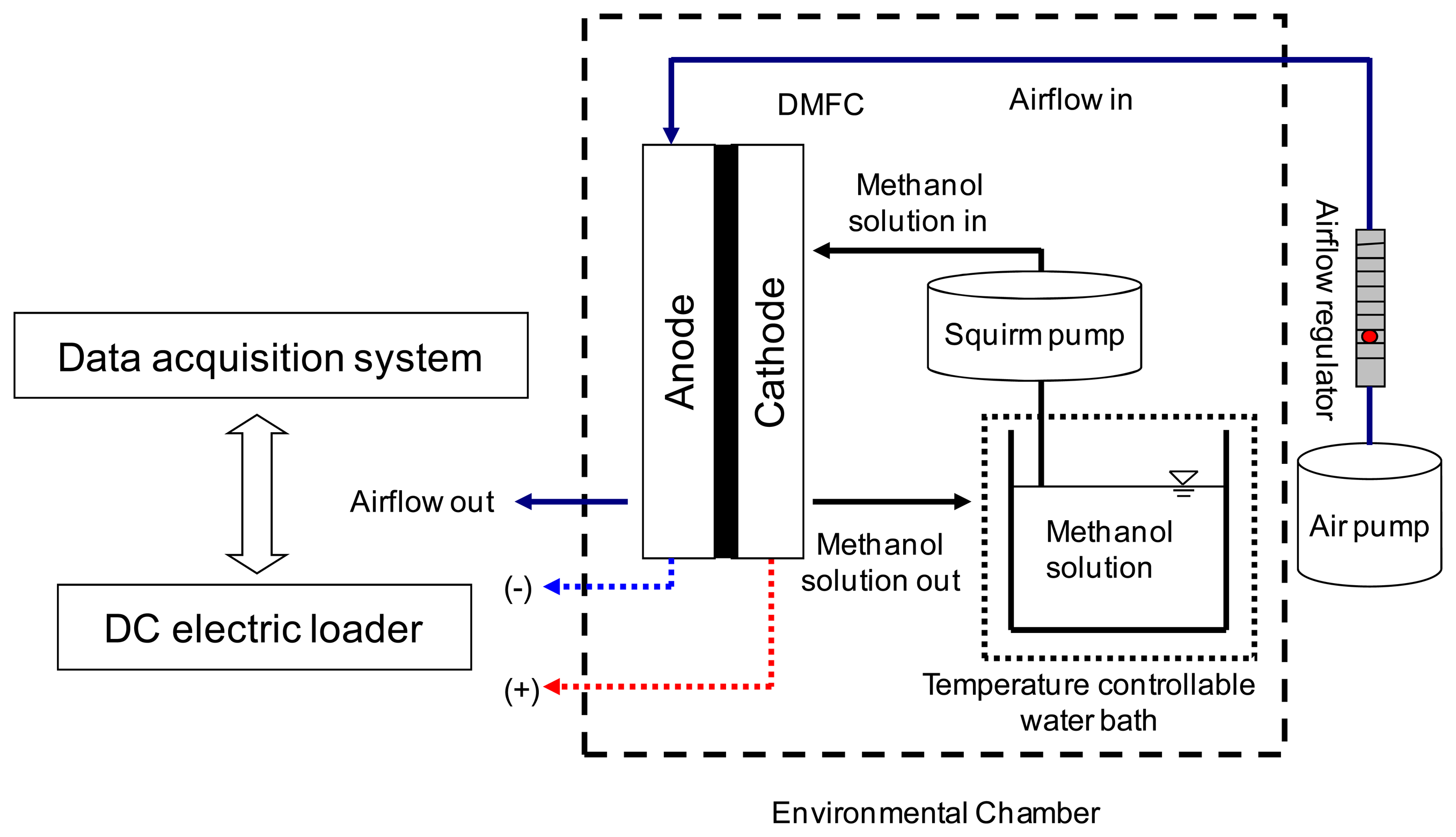
Polarization curves were measured to evaluate the performance of a single-cell disc-type DMFC with the current collectors using different thermal evaporation conditions. A sketch of the experimental setup is shown in Figure 12 to illustrate the measurement of the DMFC polarization curves. The DMFC was placed into an environmental control chamber. A methanol solution was placed in a beaker, and a temperature controllable water bath was adopted to preheat the methanol solution. A squire pump was used to pump and control the methanol solution into the DMFC anode. An air pump, with an airflow regulator, was used to pump and control the airflow over the DMFC cathode. The DMFC was loaded using a DC electric loader connected to a data acquisition card to record the related data. In the single-cell test, all experiments were conducted at 55 °C and 60% RH (Relative Humidity) in a 2 M methanol/DI (De-ionized water) water solution. The anode fuel flow rate was kept at 2 cc·min−1, and the cathode airflow rate was kept at 200 cc·min−1.
Figure 13 shows the performance comparison of a single-cell disc-type DMFC with current collectors under different conditions. All of the DMFCs with the proposed light weight current collectors showed higher cell performance than the DMFCs with stainless 316 L current collectors, a major type of convectional material. The thicker copper thin film yielded higher cell performance. The current collectors with Cu 25 kÅ/Ni 4 kÅ and Cu 25 kÅ/Ni 2 kÅ thin film layers had the highest cell performance. Although the cell performance of the current collectors with Cu 20 kÅ/Ni 2 kÅ thin films was not the highest, it is quite close to the highest cell performance. Consider the time needed for thermal evaporation processes and the amount of material consumed. Further study of the 3-cell disc-type DMFC module will adopt current collectors with Cu 20 kÅ/Ni 2 kÅ thin films.
4.3. Performance Measurements of the Three-Cell Disc-Type DMFC Module
The polarization curves of a 3-cell disctype DMFC module were measured. The current collectors of the disc-type DMFC module were coated Cu 20 kÅ/Ni 2 kÅ thin films. The experimental setup was similar to the single-cell measurement, which is shown in Figure 12. In the 3-cell DMFC module tests, all experiments were conducted at 55 °C and 60% RH in a 2 M methanol/DI water solution. The anode fuel flow rate was kept at 6 cc·min−1, and the cathode airflow rate was kept at 1000 cc·min−1. An AC (Alternating Current) liquid pump and DC (Direct Current) air pump were used to constantly supply methanol fluid and air. However, to fabricate a portable module, a diaphragm air–liquid micropump [16], which supplies both liquid and air without requiring a substantial amount of power, can be installed. The polarization curves of the current collectors using different thermal evaporation conditions were measured. The DMFC was placed into an environmental control chamber. The methanol solution was contained in a beaker, and a temperature controllable water bath was adopted to preheat the methanol solution. A squire pump was used to pump and control the methanol solution into the DMFC anode. An air pump, with an airflow regulator, was used to pump and control the airflow over the DMFC cathode. The DMFC was loaded using a DC electric loader connected to a data acquisition card to record the related data.
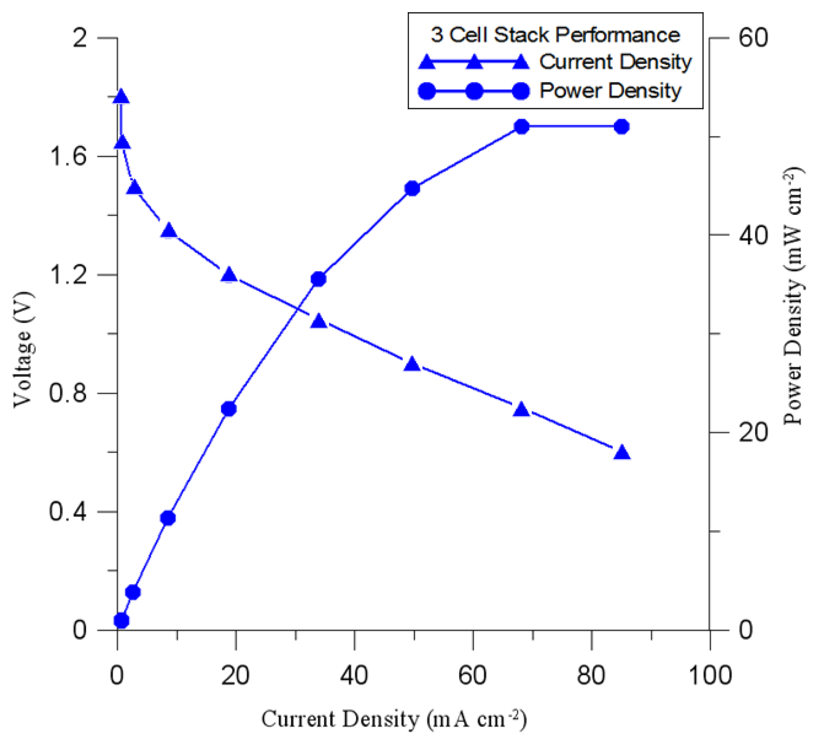
Polarization curves were measured to evaluate the single-cell disc-type DMFC's performance with current collectors using different thermal evaporation conditions. The original design adopted the PTFE as the gaskets between each layer. The measurement of the polarization curve of the 3-cell disc-type DMFC module using PTFE as the gaskets is shown in Figure 14. The current density and power density under 0.6 V electric loading were about 1.47 mA·cm−2 and 54.88 mW·cm−2, respectively. Therefore, the feasibility of the lightweight current collectors applied to the 3-cell DMFC has been successfully demonstrated.
5. Conclusions
This paper describes a three-cell disc-type DMFC module featuring lightweight (only 10 g) current collectors developed in the laboratory (the weight of SS316L current collectors is 700 g). The current collectors developed in this paper adopt FR4/Epoxy plates as the substrates. The surface of each current collector is coated with a copper thin film as the electrical conduction layer and a nickel thin film as the corrosion resistance layer. The copper thin film thickness dominates the electrical resistivity effect of the current collector. A thicker, copper thin film yields lower electrical resistivity. The performance of single-cell disc-type and SS316L current collectors was evaluated, and the results indicated that the performance of the disc-type current collector was more favorable than that of the SS613L current collector. In consideration of the cost and the time required for thermal evaporation, the three-cell disc-type DMFC module was composed of current collectors coated with Cu 20 kÅ/Ni 2 kÅ thin films. For the three-cell disc-type DMFC module, the current under a 0.6 V electrical load was approximately 1.47 mA·cm−2 (1.8 A and electrical load of each cell was 0.2 V). The performance of the three-cell module was almost identical to that of the single–cell module. Thus, the number of cells can be increased to 6, and a DC-DC converter can be used to increase the output voltage to 5 V. In summary, the developed lightweight current collectors were successfully applied to the 3-cell disc-type DMFC module and have full potential for a variety of applications in the future.
Acknowledgments
The authors would like to acknowledge financial support from the National Science Council of Taiwan. (NSC 99-2221-E-167-017-MY2 and NSC 101-2628-E-167 -001 -MY3).
Conflicts of Interest
The authors declare no conflict of interest.
References
- Larminie, J.; Dicks, A. Fuel Cell Systems Explained, 2nd ed.; John Wiley & Sons Ltd.: West Sussex, England, UK, 2003. [Google Scholar]
- Kamarudin, S.K.; Achmad, F.; Daud, W.R.W. Overview on the application of direct methanol fuel cell. Int. J. Hydrog. Energy 2009, 34, 6902–6916. [Google Scholar]
- Mehta, V.; Cooper, J.S. Review and analysis of PEM fuel cell design and manufacturing. J. Power Sources 2003, 114, 32–53. [Google Scholar]
- Middelman, E.; Kout, W.; Vogelaar, B.; Lenssen, J.; de Waal, E. Bipolar plates for PEM fuel cells. J. Power Sources 2003, 118, 44–46. [Google Scholar]
- Zhao, T. Micro Fuel Cells Principles and Applications; Elsevier Inc.: Burlington, MA, USA, 2009. [Google Scholar]
- Kumar, A.; Reddy, R.G. Materials and design development for bipolar/end plates in fuel cells. J. Power Sources 2004, 129, 62–67. [Google Scholar]
- Padhy, B.R.; Reddy, R.G. Performance of DMFC with SS 316 bipolar/end plates. J. Power Sources 2006, 153, 125–129. [Google Scholar]
- O’Hayre, R.; Braithwaite, D.; Hermann, W.; Lee, S.-J.; Fabian, T.; Cha, S.-W.; Saito, Y.; Prinz, F.B. Development of portable fuel cell arrays with printed-circuit technology. J. Power Sources 2003, 124, 459–472. [Google Scholar]
- Schmitz, A.; Traintz, M.; Wagner, S.; Hahn, R.; Hebling, C. Planar self-breathing fuel cells. J. Power Sources 2003, 118, 162–171. [Google Scholar]
- Schmitz, A.; Wagner, S.; Hahn, R.; Uzun, H.; Hebling, C. Stability of planar PEMFC in printed circuit board technology. J. Power Sources 2004, 127, 197–205. [Google Scholar]
- Lu, G.A.; Wang, C.Y.; Yeh, T.J.; Zhang, Z. Development and characterization of a silicon-based micro direct methanol fuel cell. Electrochim. Acta 2004, 49, 821–828. [Google Scholar]
- Cha, H.-Y.; Choi, H.-G.; Nam, J.-D.; Lee, Y.; Cho, S.M.; Lee, E.-S.; Lee, J.-K.; Chung, C.-H. Fabrication of all-polymer micro-DMFCs using UV-sensitive photoresist. Electrochim. Acta 2004, 50, 795–799. [Google Scholar]
- Yao, S.-C.; Tang, X.; Hsieh, C.-C.; Alyousef, Y.; Vladimer, M.; Fedder, G.K.; Amon, C.H. Micro-electro-mechanical systems (MEMS)-based micro-scale direct methanol fuel cell development. Energy 2006, 31, 636–649. [Google Scholar]
- Zhang, Y.; Lu, J.; Shimano, S.; Zhou, H.; Maeda, R. Development of MEMS-based direct methanol fuel cell with high power density using nanoimprint technology. Electrochem. Commun. 2007, 9, 1365–1368. [Google Scholar]
- Sung, M.-F.; Kuan, Y.-D.; Chen, B.-X.; Lee, S.-M. Design and fabrication of light weight current collectors for direct methanol fuel cells using the micro-electro mechanical system technique. J. Power Sources 2007, 196, 5897–5902. [Google Scholar]
- Lee, S.-M.; Kuan, Y.-D.; Sung, M.-F. Diaphragm air–liquid micro pump applicable to the direct methanol fuel cell. J. Power Sources 2013, 238, 290–295. [Google Scholar]


| Items | Point 1 | Point 2 | Point 3 | Point 4 | Average |
|---|---|---|---|---|---|
| Cu:15 kÅ; Ni:2 kÅ | 2.75 | 3.57 | 3.28 | 2.87 | 3.12 |
| Cu:15 kÅ; Ni:4 kÅ | 2.86 | 3.00 | 3.50 | 2.47 | 2.96 |
| Cu:15 kÅ; Ni:6 kÅ | 2.46 | 2.05 | 2.45 | 1.93 | 2.22 |
| Cu:20 kÅ; Ni:2 kÅ | 2.19 | 2.29 | 2.44 | 1.78 | 2.18 |
| Cu:20 kÅ; Ni:4 kÅ | 1.96 | 2.20 | 2.38 | 2.15 | 2.17 |
| Cu:20 kÅ; Ni:6 kÅ | 1.95 | 2.20 | 2.38 | 2.15 | 2.17 |
| Cu:25 kÅ; Ni:2 kÅ | 2.50 | 2.21 | 1.86 | 1.67 | 1.81 |
| Cu:25 kÅ; Ni:4 kÅ | 1.50 | 1.87 | 1.53 | 1.87 | 1.69 |
| Cu:25 kÅ; Ni:6 kÅ | 1.53 | 1.68 | 2.00 | 1.35 | 1.64 |
© 2014 by the authors; licensee MDPI, Basel, Switzerland.. This article is an open access article distributed under the terms and conditions of the Creative Commons Attribution license ( http://creativecommons.org/licenses/by/3.0/).
Share and Cite
Kuan, Y.-D.; Lee, S.-M.; Sung, M.-F. Development of a Direct Methanol Fuel Cell with Lightweight Disc Type Current Collectors. Energies 2014, 7, 3136-3147. https://doi.org/10.3390/en7053136
Kuan Y-D, Lee S-M, Sung M-F. Development of a Direct Methanol Fuel Cell with Lightweight Disc Type Current Collectors. Energies. 2014; 7(5):3136-3147. https://doi.org/10.3390/en7053136
Chicago/Turabian StyleKuan, Yean-Der, Shin-Min Lee, and Ming-Feng Sung. 2014. "Development of a Direct Methanol Fuel Cell with Lightweight Disc Type Current Collectors" Energies 7, no. 5: 3136-3147. https://doi.org/10.3390/en7053136