Battery Management System—Balancing Modularization Based on a Single Switched Capacitor and Bi-Directional DC/DC Converter with the Auxiliary Battery


Abstract
: Lithium-based batteries are considered as the most advanced batteries technology, which can be designed for high energy or high power storage systems. However, the battery cells are never fully identical due to the fabrication process, surrounding environment factors and differences between the cells tend to grow if no measures are taken. In order to have a high performance battery system, the battery cells should be continuously balanced for maintain the variation between the cells as small as possible. Without an appropriate balancing system, the individual cell voltages will differ over time and battery system capacity will decrease quickly. These issues will limit the electric range of the electric vehicle (EV) and some cells will undergo higher stress, whereby the cycle life of these cells will be shorter. Quite a lot of cell balancing/equalization topologies have been previously proposed. These balancing topologies can be categorized into passive and active balancing. Active topologies are categorized according to the active element used for storing the energy such as capacitor and/or inductive component as well as controlling switches or converters. This paper proposes an intelligent battery management system (BMS) including a battery pack charging and discharging control with a battery pack thermal management system. The BMS user input/output interfacing. The battery balancing system is based on battery pack modularization architecture. The proposed modularized balancing system has different equalization systems that operate inside and outside the modules. Innovative single switched capacitor (SSC) control strategy is proposed to balance between the battery cells in the module (inside module balancing, IMB). Novel utilization of isolated bidirectional DC/DC converter (IBC) is proposed to balance between the modules with the aid of the EV auxiliary battery (AB). Finally an experimental step-up has been implemented for the validation of the proposed balancing system.1. Introduction
Battery management systems (BMSs) are an important part of the battery system in electric vehicles (EVs) and hybrid electric vehicles (HEVs). The aim of the BMS is to protect the battery system from damage, to predict and increase batteries life, and to maintain the battery system in an accurate and reliable operational condition. The BMS performs several tasks, such as measuring the system voltage, current and temperature (VIT), the cells' state of charge (SoC), state of health (SoH) and remaining useful life (RUL) determination, protecting the cells, thermal management, controlling the charge/discharge procedure, monitoring, storing historical data, data acquisition, communication with on-board and off-board modules (may be charger), and most importantly is the cell balancing [1].
Battery systems are affected by many factors, a key one being the cells unbalancing. Imbalance of cells in a battery pack is an essential factor affecting of battery system life. Without a balancing system, the individual cell voltages will drift apart over time. The capacity of the total pack will also decrease more quickly during operation and the battery system will fail prematurely [2]. Thus, cell balancing is important for preserving the battery life. Quite a lot of cell balancing/equalization methods have been proposed such [1–39]. Furthermore, these BMS are reviewed in [1–7].
The cell imbalance is caused by internal and external sources, according to [37]. The internal sources include manufacturing variance in charge storage volume, variations in internal impedance and differences in self-discharge rate. External sources are mainly caused by some multi-rank pack protection integrated circuits (ICs), which drain charge unequally from the different series ranks in the pack. In addition the thermal difference across the pack results in different self-discharge rates of the cells [2].
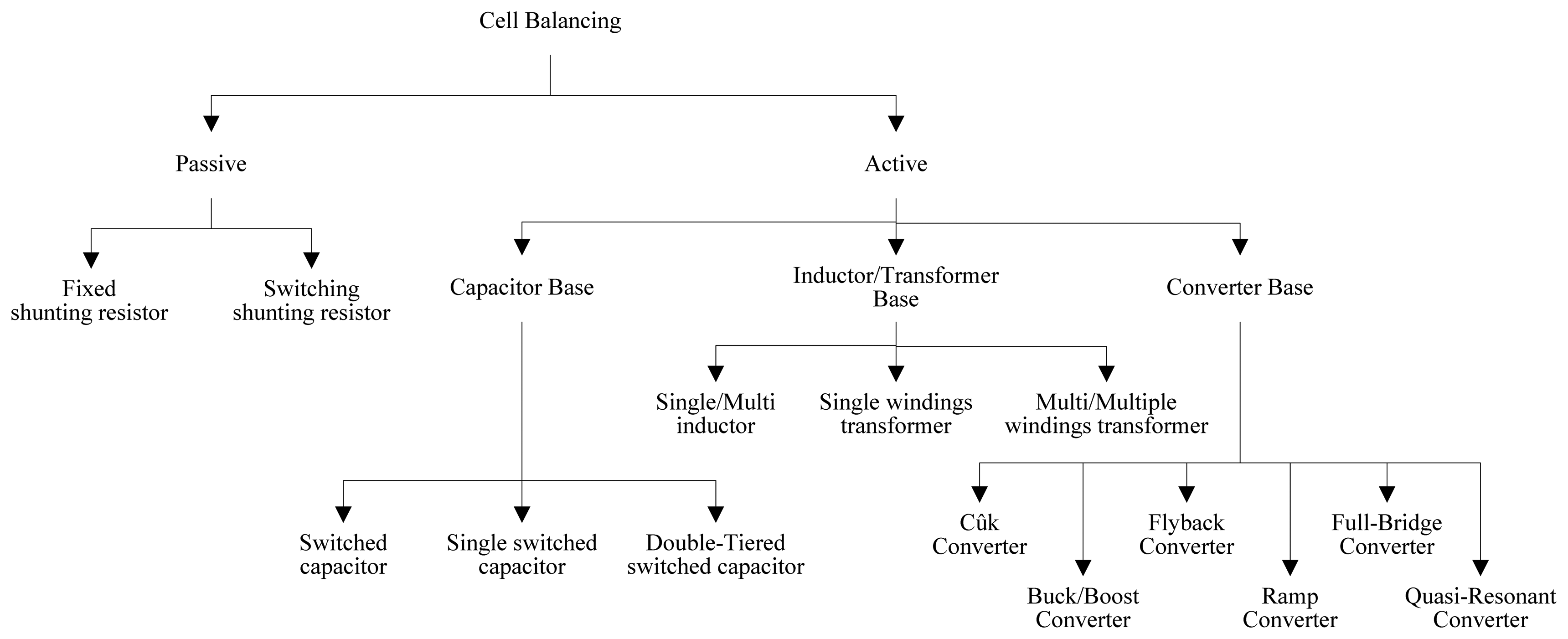
The balancing topologies can be categorized into passive and active balancing, as shown in Figure 1. The passive balancing methods remove the excess charge from the fully charged cell(s) through a passive element, resistor, until the charge matches those of the lower cells in the battery pack or matches a charge reference. The resistor element will be either in fixed mode such as [7,8] or in switched mode according the system as presented in [1–7,9–11].
The active cell balancing methods remove charge from higher energy cell(s) and deliver it to lower energy cell(s). According to this energy transfer between cells active balancing is more efficient than passive balancing. Different topologies are used according to the active element used for storing the energy such as capacitor and/or inductive component as well as controlling switches or converters as reported in [1–7,14–41].
In this paper, an intelligent BMS is proposed. The design and the implementation of the battery pack (BP) prototype are described in details. The proposed BMS includes a novel cell balancing system based on battery pack modularization. Furthermore, the selection of the system's components (such as switches, isolation circuits, gate drivers, voltages, currents, temperatures sensing circuits, microcontrollers, and interfacing circuit) are described in detail. Finally, the experimental results are presented and analyzed.
The paper is divided into nine sections: the first section presents a general introduction; the second section explores the BMS construction and tasks; the third section deals battery balancing based on pack modularization; the fourth section describes the proposed modularized balancing system; the fifth section describes the BMS simulation results; the sixth section presents experimental prototype implementation including the system's elements details; the seventh section illustrates the experimental results with various cells types and balancing techniques; the eighth section presents a suggested price for the proposed BMS; finally, the summary and conclusions are presented in the ninth section.
2. BMSs
Battery technology has been used since the invention of the first voltaic cell in the 1800s and a lot of researches have been performed for batteries and applications [40–47]. Because of the increased interest in hybrid vehicles and battery EVs, a BMS has become one of the chief components in these vehicles. The main goal of BMS is to minimize the variation between the cells in the battery pack. Therefore, the run-time per cycle can be increased, and in addition, a higher number of cycles can be achieved [48].
The functions of a BMS in HEVs and plug-in hybrid EVs (PHEVs) are multifaceted. They include monitoring the conditions of individual cells that make up the battery, maintaining all the cells within their operating limits, protecting the cells from out-of-tolerance conditions, compensating for any imbalances in cell parameters within the battery chain, providing information about the SoC, SoH, RUL of the battery, providing the optimum charging algorithm and responding to changes in the vehicle operating mode [48].
BMSs Architecture and Tasks
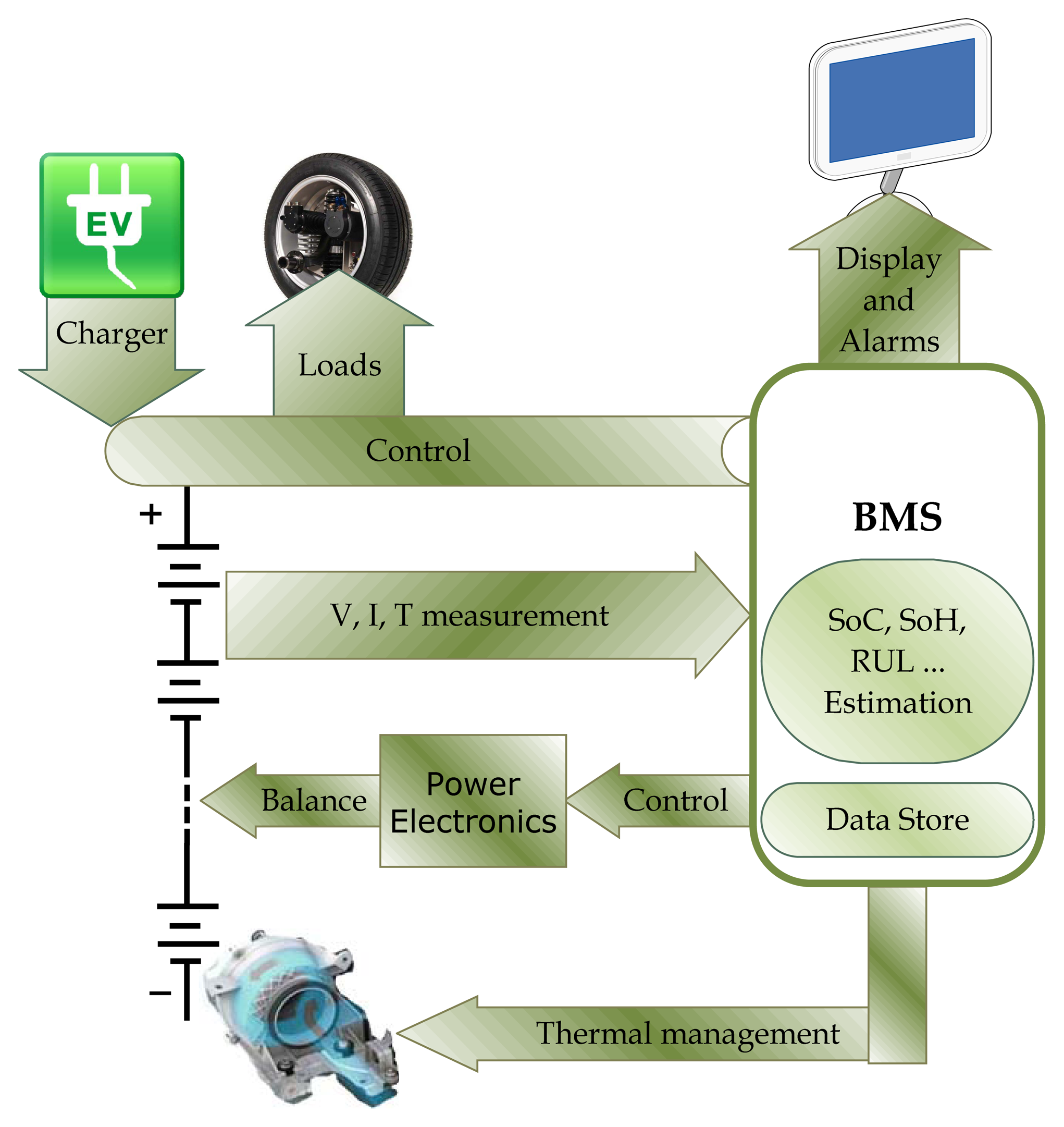
The BMS can have many configurations according to the tasks that should be performed. An example of a BMS in specify applications is shown in Figure 2.
The BMS protects the battery system from damage, predicts and increases battery life, and maintains the battery system in an accurate and reliable operating condition. Battery pack cells imbalance is a vital issue in the battery system life. The BMS performs several tasks such as measuring the system VIT, the cells' SoC, SoH, and RUL estimation as [50–54], protecting the cells, thermal management, controlling the charge/discharge procedure, data acquisition, communication with on-board/off-board modules, monitoring, storing historical data and most important task is the cell balancing [1].
3. Battery Balancing Systems Based on Pack Modularization
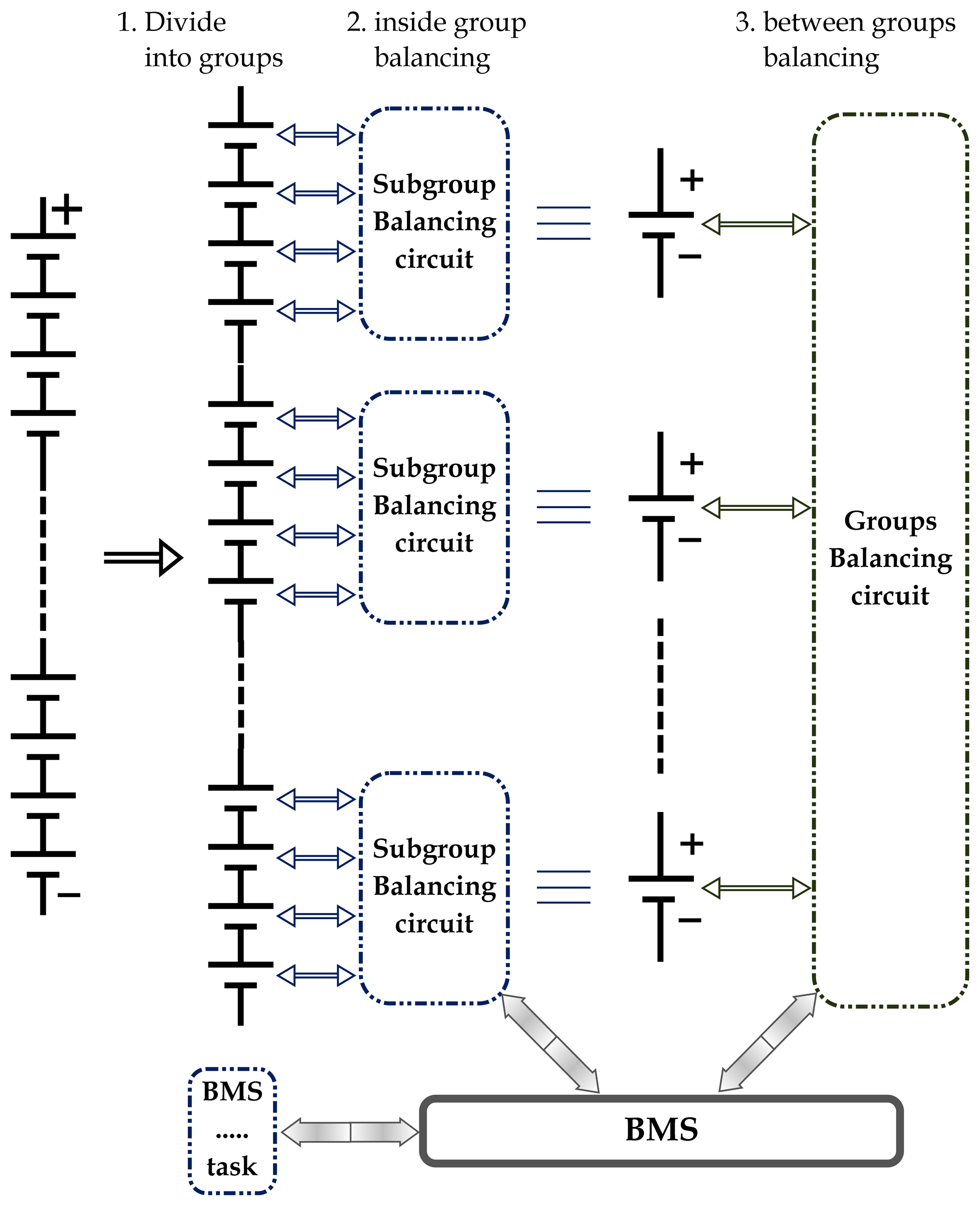
The general idea of the battery balancing topologies based on a modularization aspect is performed by dividing the battery pack into groups of cells. Inside each group there is an equalization system to balance the subgroup's cells. In addition, outside the groups there is another equalization system, which balances between the groups as shown in Figure 3, which illustrates the BMS, which includes battery balancing based on modularization. The BMS controller can be implemented by using one processing system, which manages the subgroups and balances the various groups. In addition, the master-slaves control topology can be implemented with the cells groups. Each subgroup balancing circuit is controlled by one slave controller, as well as, the groups balancing circuit is controlled by another slave controller and the BMS block reflects the master controller.
3.1. Battery Pack Modularization Review
Several modularized balancing systems were proposed. Inside these subgroups (modules), different balancing schemes were proposed such as switched resistor, switched capacitor, single switched capacitor (SSC), single switched inductor (SI) and single switched transformer. The balancing systems between the modules are the switched capacitor, SSC, SI, single SI and DC/DC converters, which can be implemented.
In [17], a modularized balancing topology is proposed, which gives fast balancing using the multi-winding transformer. It uses the multi-winding transformer (MWT) for balancing inside and outside the modules. Moreover, it proposes the switching capacitor equalization system as another balancing system for comparison. Unfortunately, using the switched capacitor outside the modules will increase the balancing system size and cost. In addition, there are losses in the transformer of the MWT balancing system.
In [55], the buck, boost and buck-boost (bi-directional) DC/DC converters are used for energy transfer between battery pack's cells. Unfortunately, with the long battery pack stack (100 cells for a typical battery pack system of 330 V nominal voltage) the usage of the DC converters for each cell will be very expensive. Dividing the battery pack into groups will allow the use of the DC converters for balancing between the groups that will reduce the balancing system cost and result in a high-energy efficiency. Here, in these cases the balancing system must have another cell balancing technique and protection system inside the modules.
Several DC converter topologies are used for cell (module) balancing. Some converters (e.g., buck) balancing are based on transferring the energy from battery pack to the cell(s). Other converters (e.g., boost converters) utilize energy transfer from cell(s) to the battery pack. Third converters (bi-directional) are balance between cells or modules. Another converter (bi-directional) topology is based on balancing between cell(s) and DC-link bus.
3.2. Battery Pack Modularization Advantages
Modularization of large battery pack (e.g., with 100 cells or more) is done by dividing the pack's cells into groups, often corresponding to physical multi-cell modules. The battery pack modularization topologies (cells grouping) have several advantages such as:
Dividing the battery pack into groups that will reduce the balancing control strategy complexity by performing the tasks from one controller over several controllers. In addition, it makes the control system structure simple.
It increases the battery system efficiency by decrease the energy losses during energy transfer along the battery string. Especially if the balancing uses cell-to-cell equalization, such as switched capacitor (SC) and SI, with a long battery string.
Using different balancing topologies inside and outside the modules offer the benefits of these various topologies, such as, low cost, high energy efficiency, fast balancing time, etc.
The cell(s) or module(s) can easily be installed and removed.
Reducing the switches' voltage and/or current stress.
Reducing the active balancing element (capacitor, inductor) size and cost, e.g., using SSC with 16 V is smaller, safer and cheaper than using SSC with 50 V or higher.
4. Proposed Battery Balancing Modularization Based on SSC and Bi-Directional DC Converter with the EV's Auxiliary Battery (AB)
Proceeding from the advantages of the modularized balancing system and combining them with the advantages of the shuttling capacitor and the DC converters active balancing systems, an innovative balancing system is established.
Usually in the EVs, there is an isolated buck DC converter. It is connected between the main battery pack (high voltage) and the EV small AB (low voltage). The AB is used for lighting, low power applications and the control systems. This converter is used for recharging the AB. It must be isolated DC-DC converter to separate the high voltage battery pack and the low voltage AB, the EV's body, as well.
The proposed balancing system is based on battery pack modularization with an isolated bi-directional DC-DC converter (IBC) and SSC balancing according to the following steps:
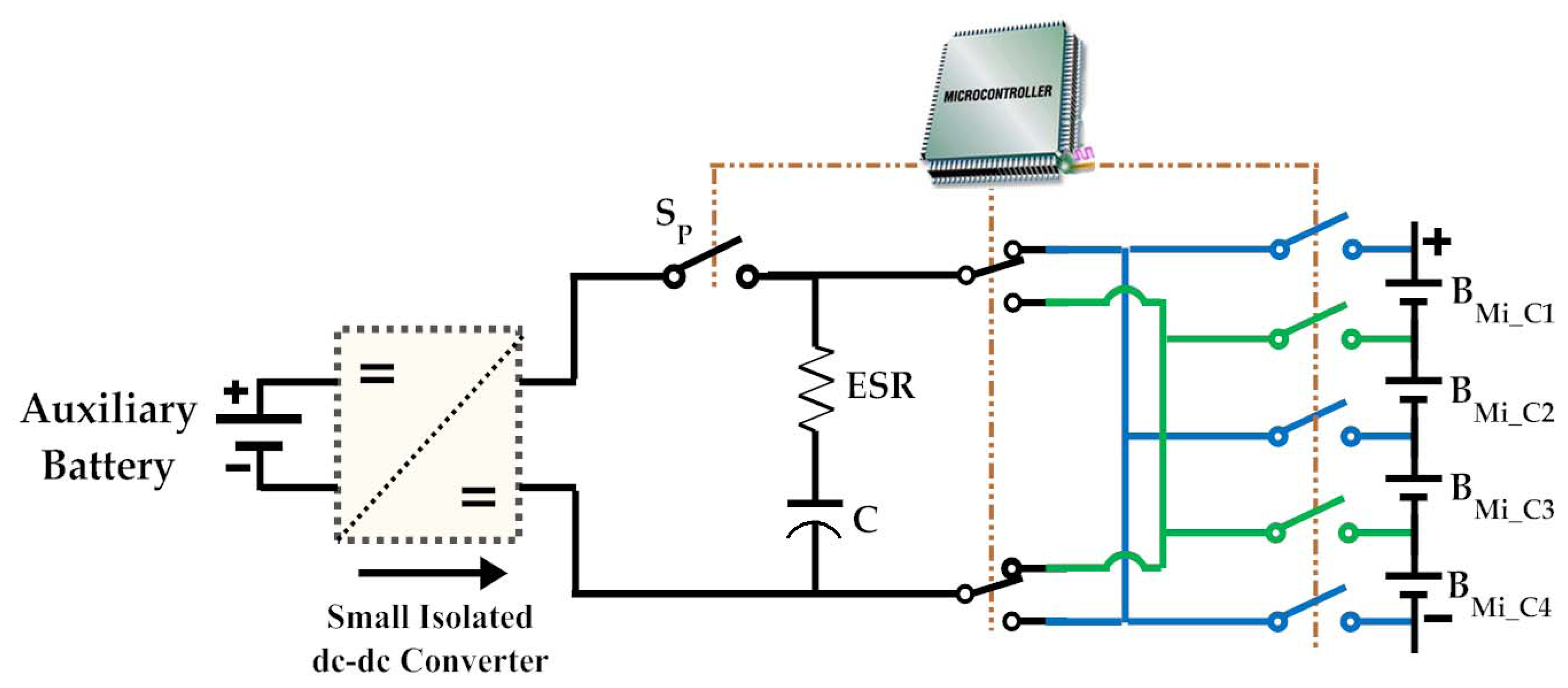
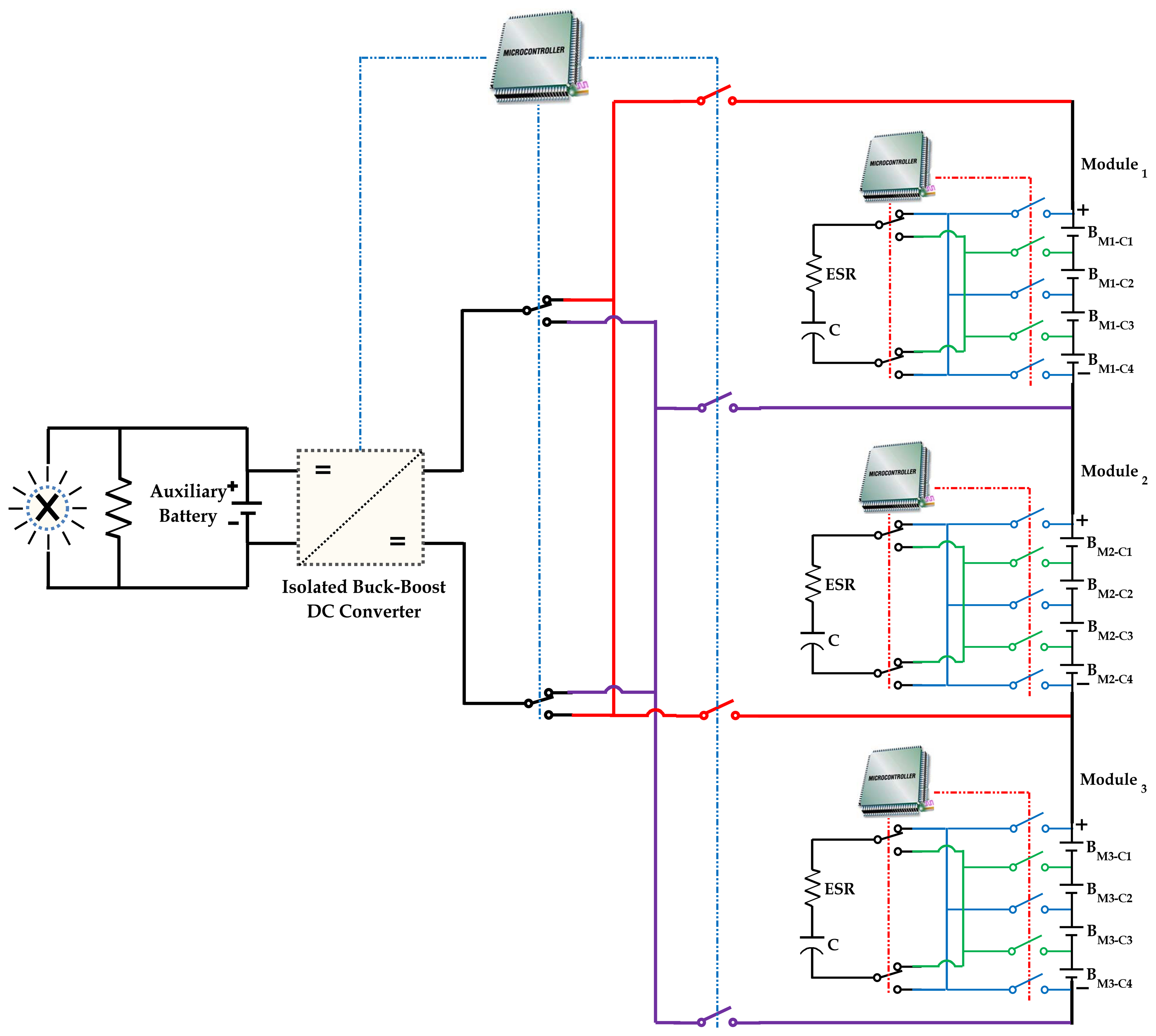
Dividing the battery pack into modules (set of cells) and construct the corresponding switching system. By using one IBC as shown in Figure 4, the energy can be transferred between the modules and the AB. This balancing topology is based on transferring the excess energy from the higher module into the AB through the IBC, and then it transfers the energy again to the lower module till the modules are balanced well. In this configuration, there is no need for the conventional buck converter, where the AB can be recharged by using the proposed bi-directional balancing converter. As a result, no high cost will be added into EV when replacing the conventional buck converter by the proposed IBC.
The second part of the proposed balancing system is using the SSC balancing circuits as illustrated in the right-hand side part of Figure 4, for balancing between the cells inside the module. So that, there is one SSC balancing circuit per module.
The complete modularized balancing system is shown in Figure 4. A prototype of 12 lithium-ion cells of 20 A·h is proposed for simulation and experimental prototype. The pack is divided into three modules with four cells per module. The balancing system consists of three SSC circuits, which will balance between cells inside the modules and one isolated bi-directional DC-DC converter to balance between the modules through the AB.
The proposed control system approach is based on master-slaves strategy, where the balancing inside the groups has been managed by one slave controller (e.g., microcontroller). Also, the balancing between the modules has been achieved by using another slave microcontroller. All these slaves are connected and managed by one master microcontroller. The tasks of the master and slaves are described below:
The first slaves' (inside modules) microcontroller tasks: these microcontrollers record the subgroup cells information (voltages V, current I, and temperature T). According to these data, the microcontroller takes the decision of subgroups cells balancing. If the cells need balancing, the controller select the higher and the lower energy cells then start balancing by proposed control strategy to the corresponding switches. In addition, if the module's temperature is high, the microcontroller activates the cooling system.
The second section is the master microcontroller. It reads the cells/modules data (V, I and T) from the slaves. Then it sends the modules (V, I and T) data to the slave No. 4 (the converter's slave). In addition, the master microcontroller controls the interfacing between the modules, user interfacing keypad and display screen.
The converter's microcontroller. This slave microcontroller reads the modules and the AB information from the master controller. If the modules need to be balanced, the battery pack and the AB can perform the balancing. The slave microcontroller selects the higher energy module and connects it to the AB for a certain time. Then it connects the lower energy module to the AB at the same time as well. In addition, the slave microcontroller controls the cooling of the electronic circuits.
5. Modularized SSC/Bidirectional DC/DC Converter (BC) Balancing System Simulation
In this section the proposed balancing system as described in Section 4 is simulated by using MATLAB/Simulink®. This kind of simulation is performed for verifying the power circuits' validity. In other words, it simulates the battery pack including the SSC and BC balancing for cells' energy transferring verification (power circuit).
5.1. SSC Modules Internal Balancing Model
The prototype consists of 12 cells in series. Each cell has a capacity of 20 A·h and rated voltage of 3.65 V, while the package voltage is around 43.8 V. This battery pack is divided into 3 series of modules with four cells per module.
Sub-module or inside module balancing (IMB) system is realized by using a modified single-switched capacitor balancing system. The proposed system can achieve the balancing between the cells inside each module. It means that each module has its own SSC balancing system. The proposed SSC balancing-system schematic diagram is shown in Figure 5.
Figure 5 shows the model of one SSC-IMB. The model consists of: four cells of the module, AB (for the SSC capacitor boosting), balancing capacitor, switching devices, and the controller. As shown in Figure 5, the SSC-MIB can be described as follows:
The SSC uses nine (n + 5) switches to balance the cells of the module “No. i”, where i indicates the module number 1, 2 and 3. The switches shown in Figure 5 are five at the battery output; two for each bidirectional switch block and one “Sp” for the capacitor boosting. All switches are bidirectional switches expect the switch, which is named as “Sp”. In one case, this switch can be connected to the cell +ve terminal. However, in another case it can be connected to another cell −ve terminal. In other word, the current will path in both directions during charging and discharging operating modes.
The AB supplies the small isolated DC-DC converter (for capacitor boosting), as well as the whole BMS electronics circuits.
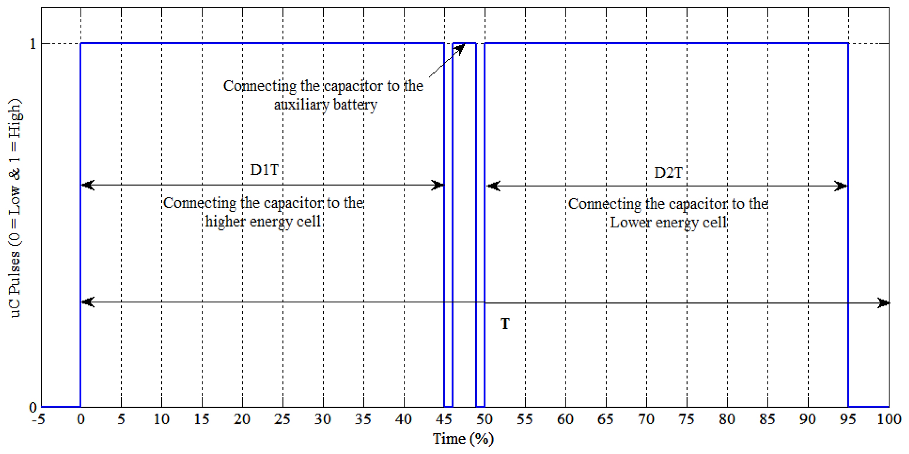
The control of these switches has been implemented by the control pulses as shown in Figure 6. The control pulses are generated in each module according to the following phases:
Selecting the higher and the lower energy cells;
Connecting the capacitor to the higher charged cell during the period D1T or DT (capacitor charging);
Rest period (determined according to the cells capacity and the energy difference between cells);
Connecting the capacitor to the AB for capacitor voltage boosting through a small DC/DC converter (capacitor boosting);
Rest period, it means that all switches are turned-off;
Connecting the capacitor to the lower charged cell during the period D2T = DT (capacitor discharging);
Rest period.
5.2. BC, MB Model
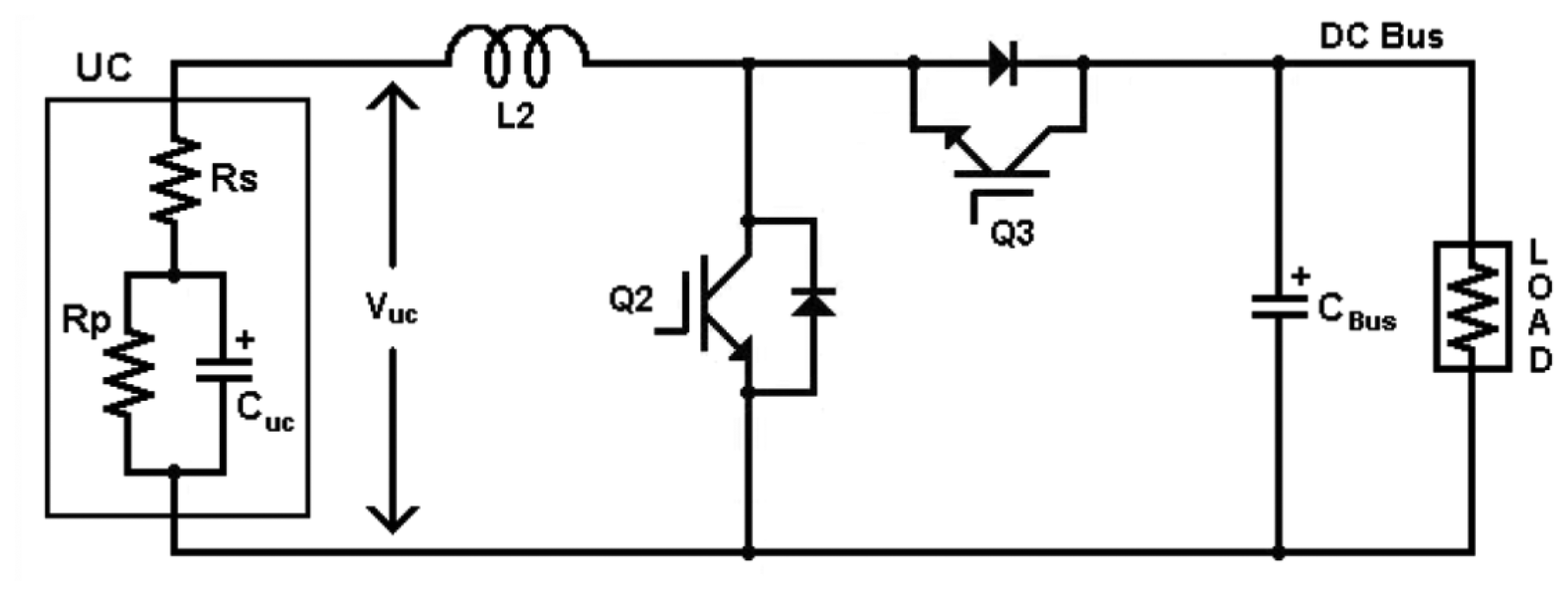
The module balancing (MB) or the balancing between the modules (module ↔ converter ↔ AB) utilizes one BC with the auxiliary. The Simulink model of the BC is designed as proposed in [56,57]. The simulated DC/DC converter is a non-isolated BC as shown in Figure 7. The BC simulation is done by using one non-isolated BC as shown in Figure 7 with the aid of MATLAB/Simulink tools with full control system.
The control of converter is implemented by using another slave controller. The master controller collects the models cells' voltages from the slaves then it sends the modules voltages to the converter slave controller. According to these measurements, the converter's controller connects the higher energy module into the AB (buck mode or high module discharging) for a certain time e.g., 1 min. After that the controller connects the AB into the lower energy module (boost mode or low module charging) for the same time 1 min.
The cell charging and discharging timing is changed according to the cells nominal capacities and the difference between the modules. As the cells capacity or the modules voltage differences are decreasing as the converter connecting periods are decreasing too.
5.3. Simulation Results
Two simulations tests are performed into the proposed balancing system (the whole battery pack) to analyze the balancing system performances:
The first simulation is executed by using the modularization system with the SSC balancing only. Taking into account that this SSC balancing did not use the boosting technique;
The second simulation is performed by using the modularization system with the internal SSC (including boosting technique) balancing and the BC balancing between the modules.
The simulations are obtained according to the next assumed conditions:
The initial SoC of the modules' cells are:
- ○
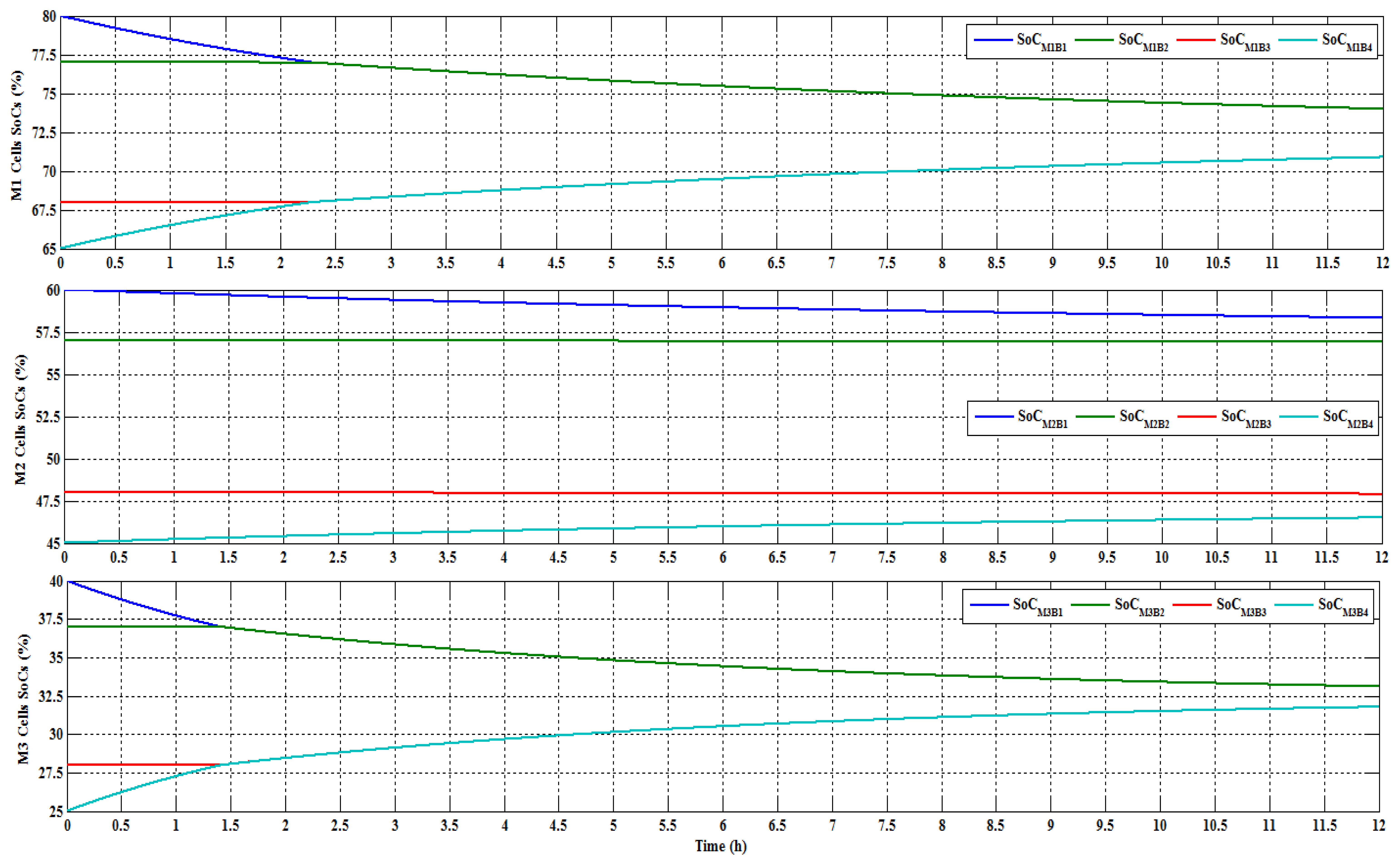
Module 1, 80%, 77%, 68% and 65% SoC for Cell 1, 2, 3 and 4, respectively;
- ○
Module 2, 60%, 57%, 48% and 45% SoC for Cell 5, 6, 7 and 8, respectively;
- ○
Module 3, 40%, 37%, 28% and 25% SoC for Cell 9, 10, 11 and 12, respectively.
The module's cells balancing are occurred when the maximum difference of the cells' SoC is around 5%.
Each module has its SSC balancing with individual control systems.
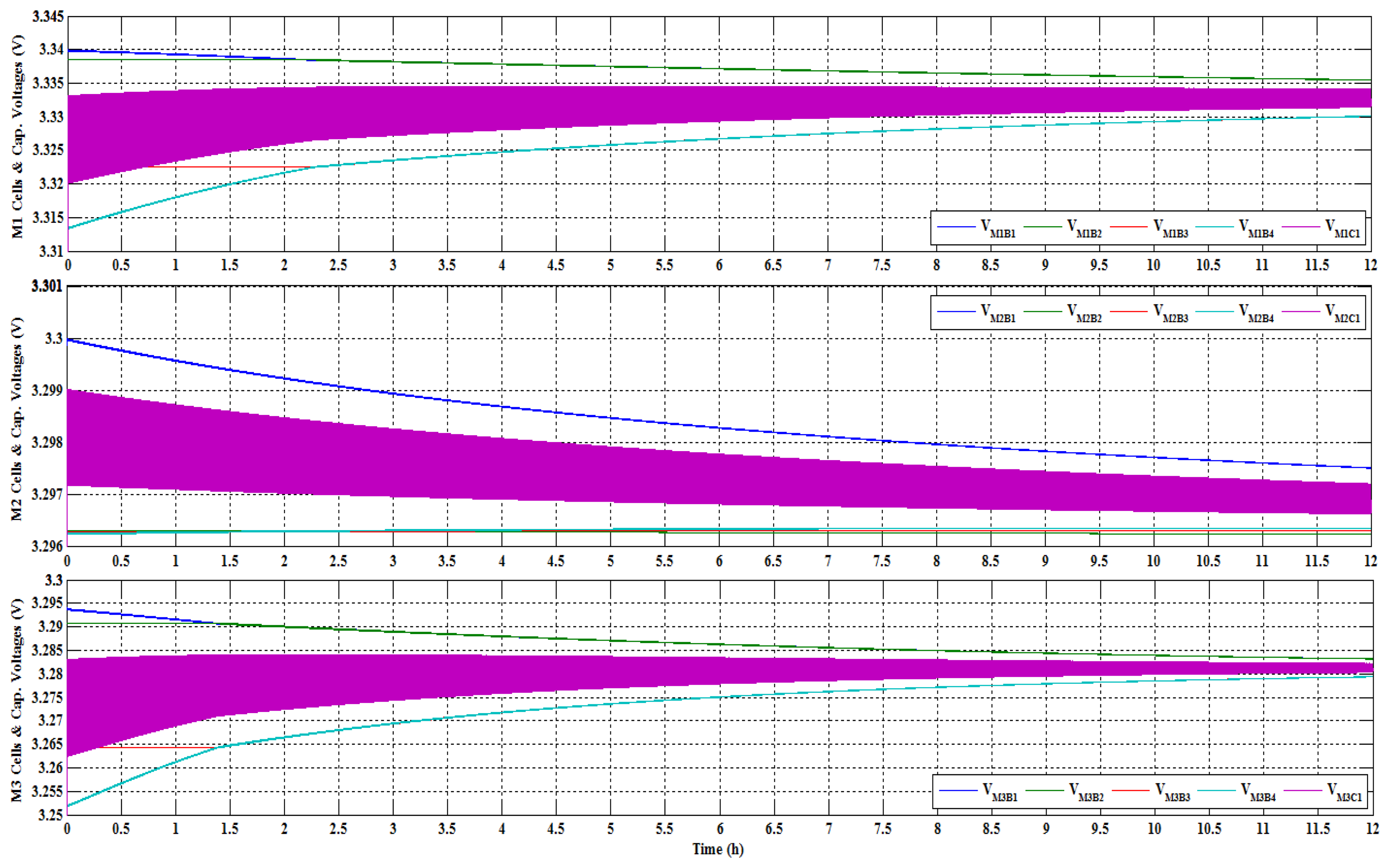
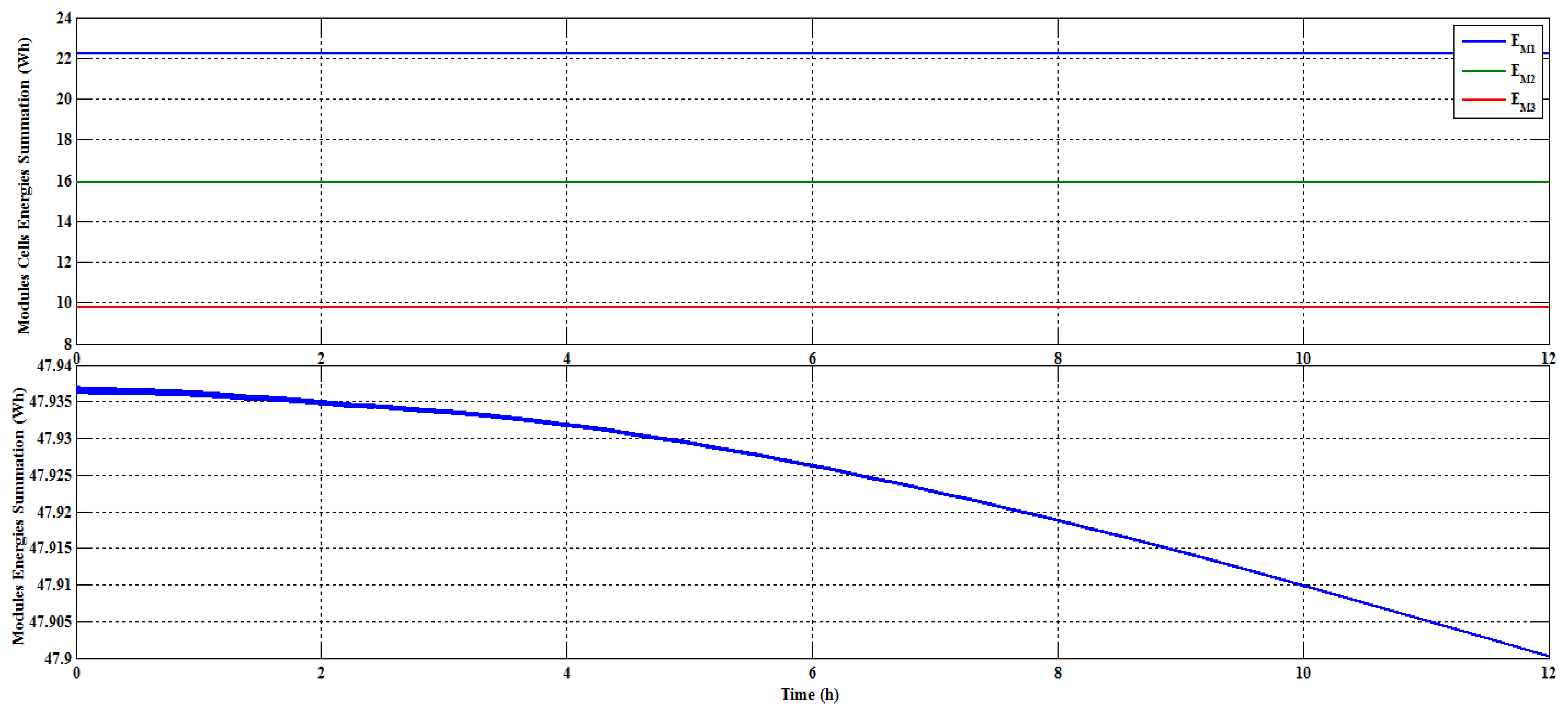
Figures 8, 9 and 10 show the simulation results. Figure 8 shows the cells voltages for the three modules including the SSC voltage of each module. Figure 9 presents the cells SoCs in each module. Finally, Figure 10 shows the modules energies and the modules energies summation.
As initial conclusions of the first simulation results, the figures show that:
- ○
The second module result, located in the middle section of Figure 9, gives a bigger SoC difference than the other two modules. Because these modules' cells are located in the lithium iron phosphate (LFP) flat voltage region. Therefore small voltage difference gives high SoC differences.
- ○
The system energy as shown at the bottom of Figure 10 is 47.937 W·h when the balancing starts and 47.9 W·h at end of balancing. That means the energy losses during the test are 0.037 W·h. This gives an energy efficiency of 99.9%.
The conclusions of the analyzed simulation results are presented in Table 1.
Figure 11 shows the cells voltages for the three modules including the SSC voltage for each module. Figure 12 presents the cells SoCs in each module. Finally, Figure 13 shows the modules energies, modules energies summation and AB energy.
The proposed balancing system presented in the second simulation runs only for nearly 3 h. As a reason of the huge memory and long simulation time of the BC and SSCs complicated systems are needed by the simulation system. According to the second simulation results as shown above, other conclusions are cleared as follows:
- ○
The DC/DC converter transfers high amount of energy (6.1 W·h) from the first module into the module in a very small time (5 min) with balancing current of 8 A. It is clear that the converter reduces the balancing time significantly.
- ○
The maximum differences of modules SoCs as shown in Figure 9 at time t = 2.75 h are 12%, 13% and 12%, respectively. The same maximum differences of modules SoCs as illustrated in Figure 12 at the same time are 8%, 14% and 7%, respectively.
The conclusions of the simulation results are presented in Table 1. Table 1 gives the comparison between the 12 cells battery pack modularization balancing using the SSC for each module only and using the SSC with the BC.
As can be seen from the previous Figures and Table 1, following conclusions can be summarized:
The first simulation results:
- ○
This simulation has internal MB system only, and there is no balancing between the modules. Therefore, there are big differences between the modules energies.
- ○
Modules one and three give very small SoC differences at end of balance (3% and 1.5%).
- ○
The SSC balancing without the boosting technique did not give acceptable results for the middle module. Where the maximum SoC difference was 12% after 12 h of balancing. Because these modules' cells are located in the FLP flat voltage region.
- ○
The system energy shown at the bottom of Figure 10 is 47.937 W·h when balancing starts and 47.9 at the end of test. Consequently the energy loss during the test is 0.037 W·h. This gives an energy efficiency of 99.9%.
The second simulation results based on the first 2.75 h of balancing:
- ○
As shown in Figure 11 and Table 1, the DC/DC converter operates only in the first 5 min of the balancing process. It transfers the energy from the higher module (M1) to the lower module (M3). Thus these three modules have nearly the same energies.
- ○
The middle module (M2; has a maximum SoC difference of 13% using the proposed SSC balancing against 14% in the first test using the traditional SSC balancing.
- ○
The first and the third modules (M1 and M3) have higher maximum SoC difference (12% and 12%) than the same results of the first test (8% and 7%). The reason is that after the converter balancing, the two modules are going to the open-circuit-voltage versus SoC (OCV-SoC) flat region. Thus the cells voltage difference and balancing current become smaller.
- ○
The converter can take the second and the third module upper away from this OCV-SoC flat region. In this case the balancing of the three modules is faster.
6. Modularized SSC/BC Balancing System Prototype
This section describes the Proteus/ISIS® (Labcenter Electronics Ltd., Grassington, UK) models implementation, as well as the experimental setup including the system component description and selection.
As explained in the previous sections (specify) the prototype battery pack of 12 cells in series with 20 A·h and 43.8 V has been implemented experimentally. The SSC is used for achieving the IMB. However, the balancing between the modules is realized by using BC.
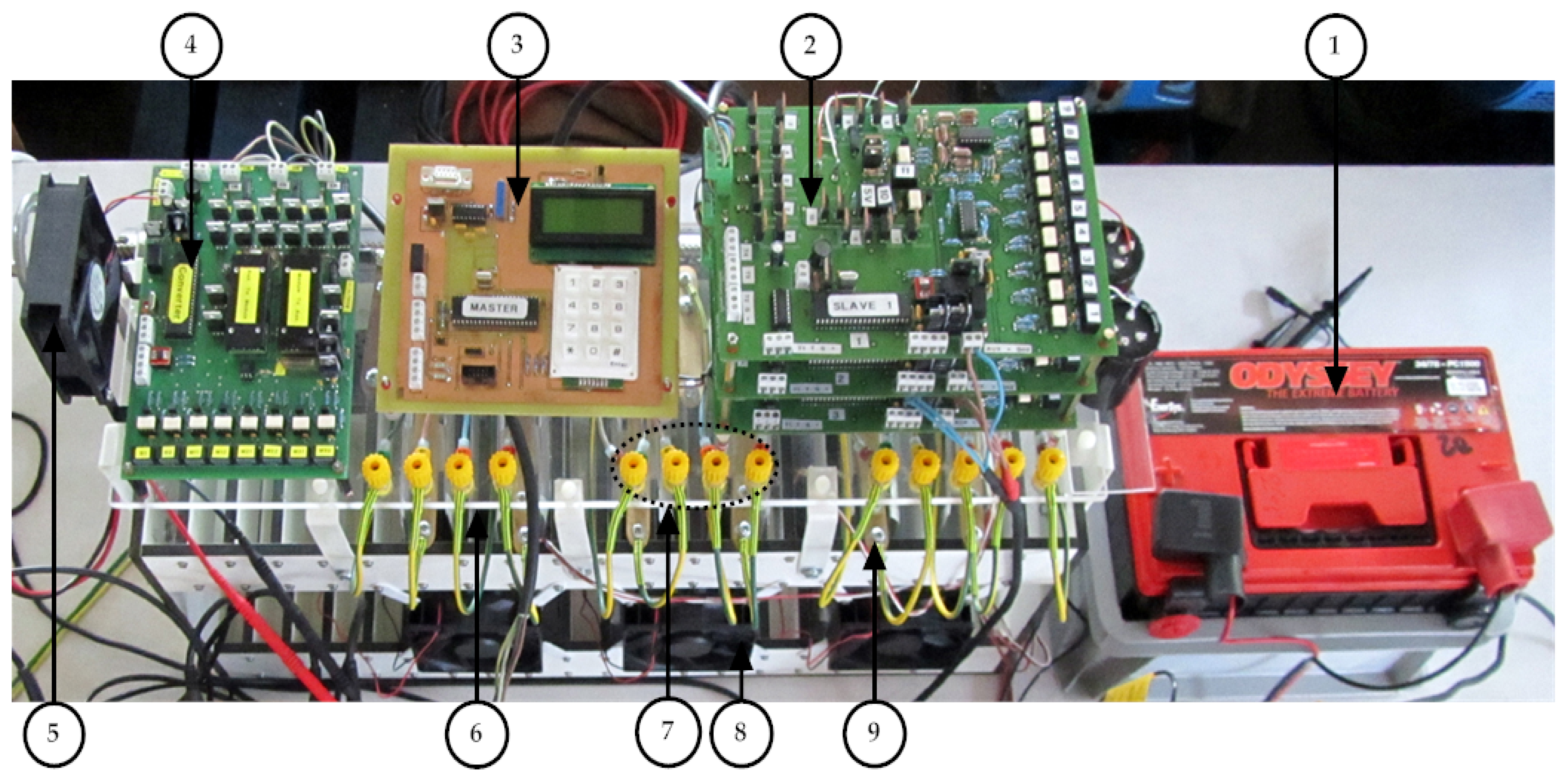
The prototype consists of three modules (four cells per module) with one control circuit per module, which is controlled by using one slave microcontroller. In addition, another slave circuit is used for controlling the BC balancing. The four slaves are monitored by the master microcontroller, which controls the interfacing between the slaves. In addition, the master microcontroller circuit has an input/output user interface. The complete prototype is shown in Figure 14.
Figure 14 shows the battery pack prototype with the proposed modularization balancing system. As shown the system consists of the following items:
- (1)
An AB;
- (2)
Three slaves control circuits for IMB (SSC balance circuit);
- (3)
The master circuit with user interfacing keypad and display screen;
- (4)
IBC converter control circuit;
- (5)
Fan for system circuits cooling;
- (6)
Battery pack modules (three modules, four cells/module, 20 A·h);
- (7)
Cells external connectors;
- (8)
Fans for modules cooling;
- (9)
Cells gathering connectors.
The prototype circuits are described in the following sections in detail.
6.1. SSC Modules Internal Balancing Circuit Implementation
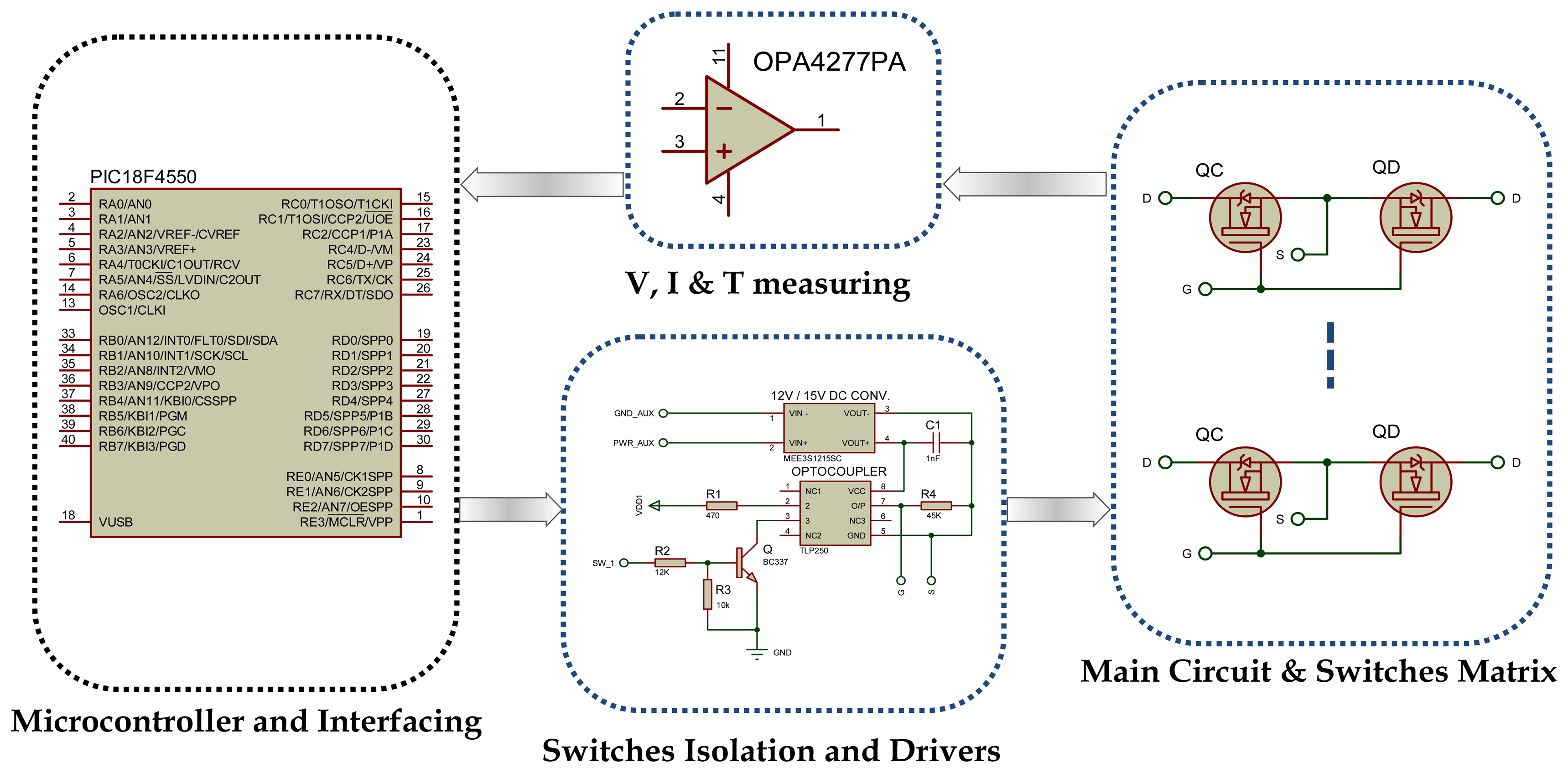
The SSC balancing slaves (1, 2 and 3) control circuits are simulated by using Proteus/ISIS simulation program. The simulation using the ISIS program is the primary step to implement the experimental control circuit. This simulation model can investigate the proposed control strategy by using the microcontroller. The circuits' PCB can be generated by using ISIS program as well. The circuit of each slave explanation is divided into four parts as shown in Figure 15.
As shown in Figure 15, the slave circuit comprises four parts, which are given as follow:
The SSC main circuit including the cells connectors, the switches matrix and the capacitor;
The switches isolation opto-couplers and driving circuit;
Power supply circuit, sensors (current, voltage temperature sensors) and fan control circuit;
The microcontroller circuit including I2C interfacing.
6.2. Switches, Isolation and Driving Circuit
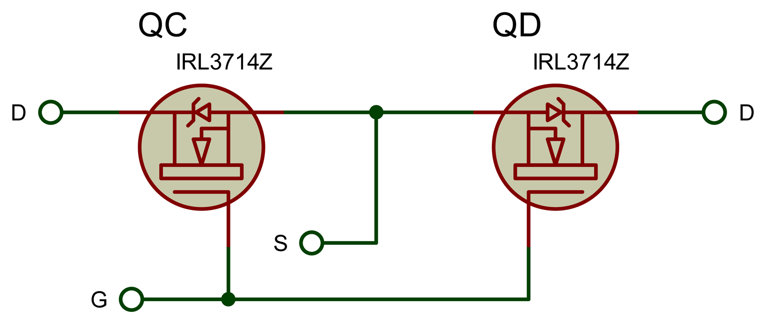
SSC's bidirectional switches matrix. The power flow through the switches is in both directions. Therefore the switches must be bidirectional. The bidirectional switches are implemented by using two anti-series MOSFETs “IRFB3806PBF” (see Figure 16) with a rating of 60 V, 43 A and 15 mΩ (maximum on-resistor) [49].
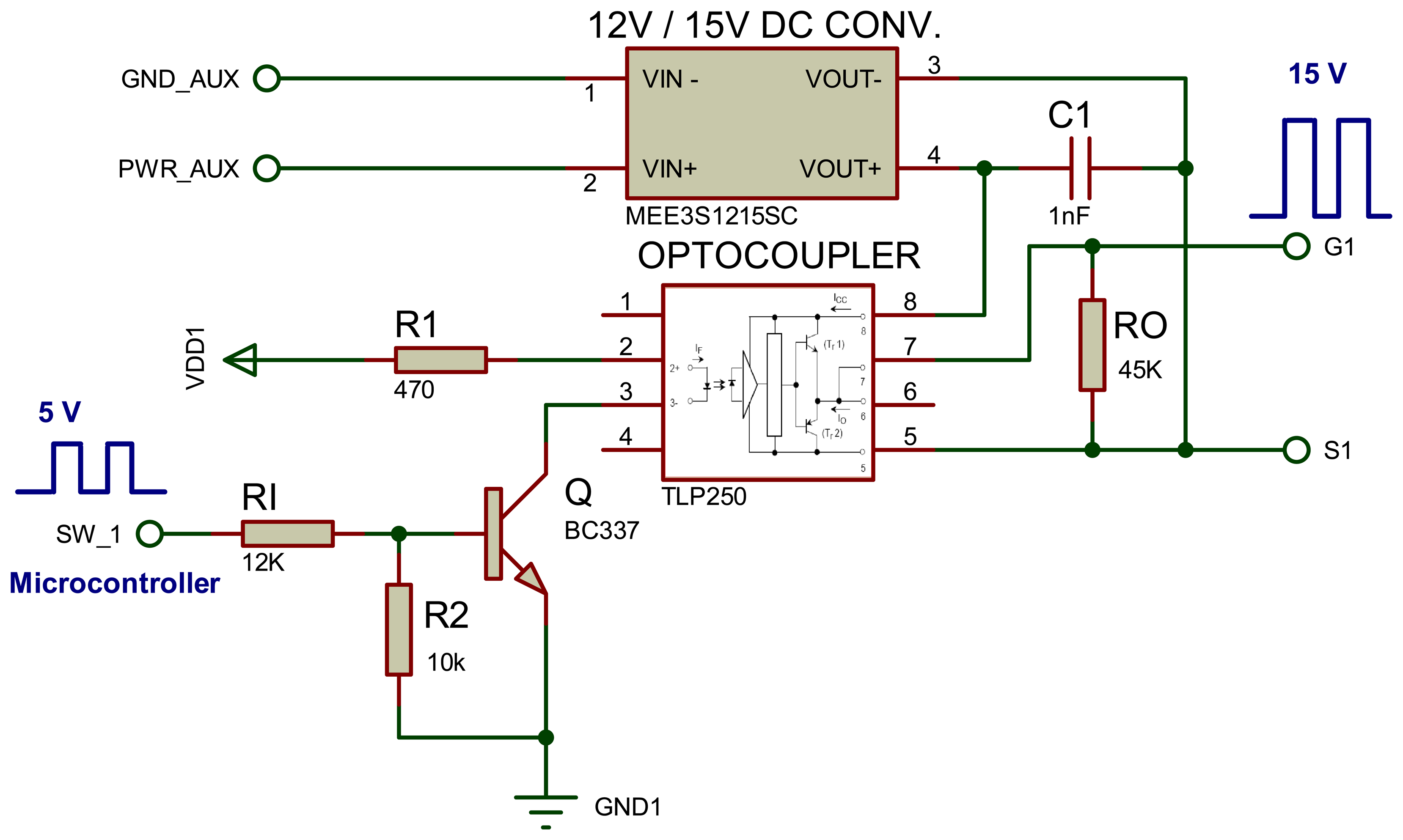
The second part of the SSC slave-control circuit is shown in Figure 17. It illustrates the switches isolation and driver circuits. This circuit provides the isolation between the control circuit (microcontroller) and the power circuits (switches), as well as, isolation between the matrix switches. The implementation of the switches isolation driver-circuit is tested by using TLP250, opto-coupler as shown in Figure 17 [49].
As shown in Figure 17, the DC source of each opto-coupler's output is obtained from a small isolated DC/DC converter, which is mentioned before (MEE3-series family, MEE3S1215SC) but with 12/15 V voltage ratio and 0.2 A output current rating (3 W) [49]. These driver converters are supplied from the AB. One converter for each bidirectional switch is implemented to ensure the full isolation between the power circuits.
6.3. Power Supply, Cooling Fan, Current, Voltage and Temperature Measurements
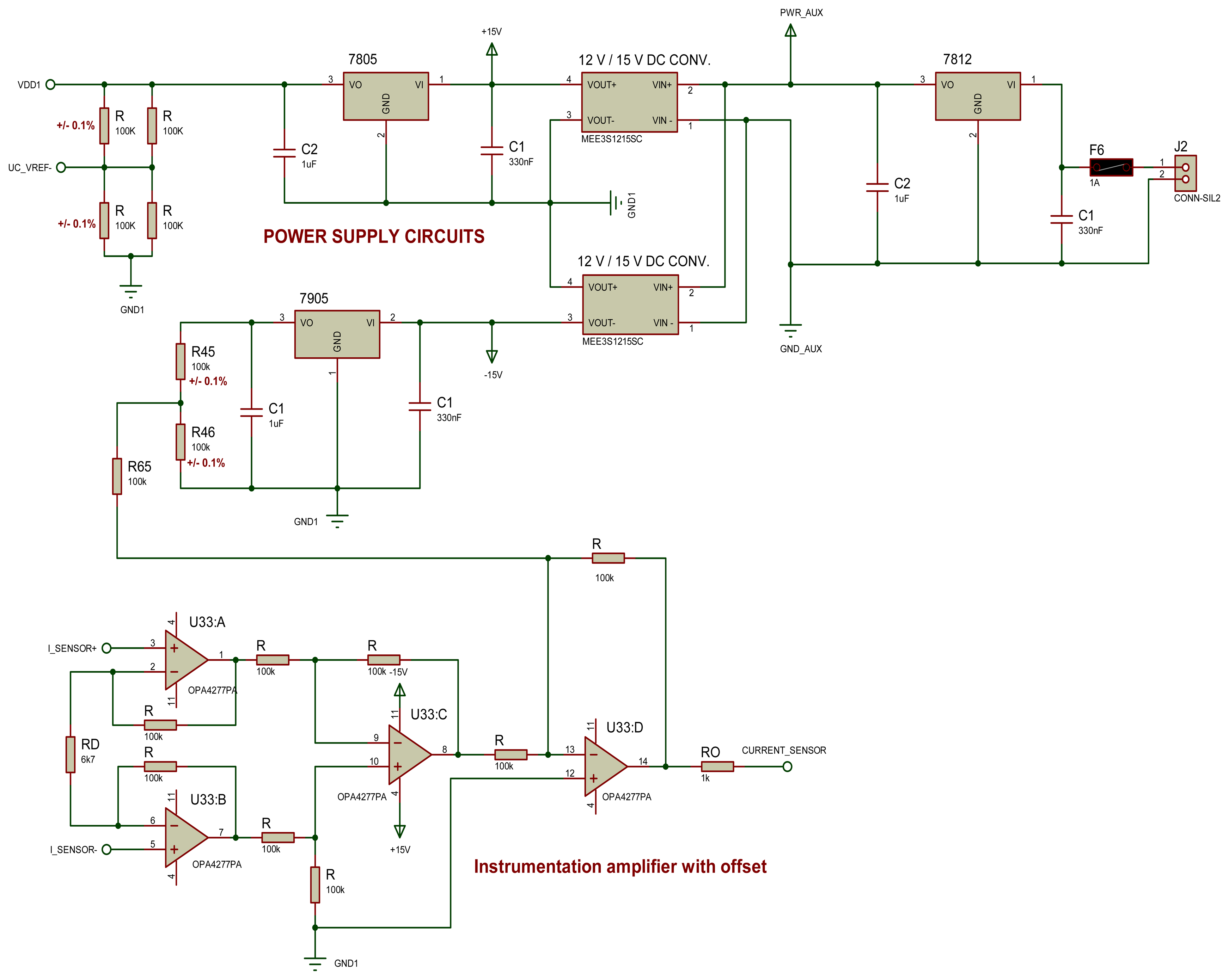
The third section of SSC slave-control circuit is the circuit power supply, cooling fan circuit, VIT sensing implementation. The SSC power supply and the capacitor balancing current sensing are shown in Figure 18.
The slave circuit power supply is shown in the top of Figure 18. The power circuit is supplied from the AB through a 7812-voltage regulator. Then two MEE3S1215SC 3 W isolated converters are implemented to have ±15 V sources. One of these converters (+15 V) is followed by a 7805-voltage regulator to have +5 V (VDD) for the microcontroller. In addition, voltage divider resistors are implemented to have +2.5 V as a reference for the microcontroller ADC in order to increase the accuracy of the VIT measurements. The second converter (−15 V) is followed by a 7905-voltage regulator to have −5 V for current sensing circuit.
Current sensor amplifier is illustrated in the bottom of Figure 18. The SSC balancing current is measured through Rs with 10 mΩ resistor, which is serially connected to the capacitor. Then this current is amplified and reversed through three amplified modules. After that, this amplified reversed current is summed with an additional offset and reversed again. Consequently, changes of the negative current values into positive values to be measurable by the microcontroller. This circuit is executed using one op-amp module “LM324AN” that has four internal built-in op-amps internally [49].
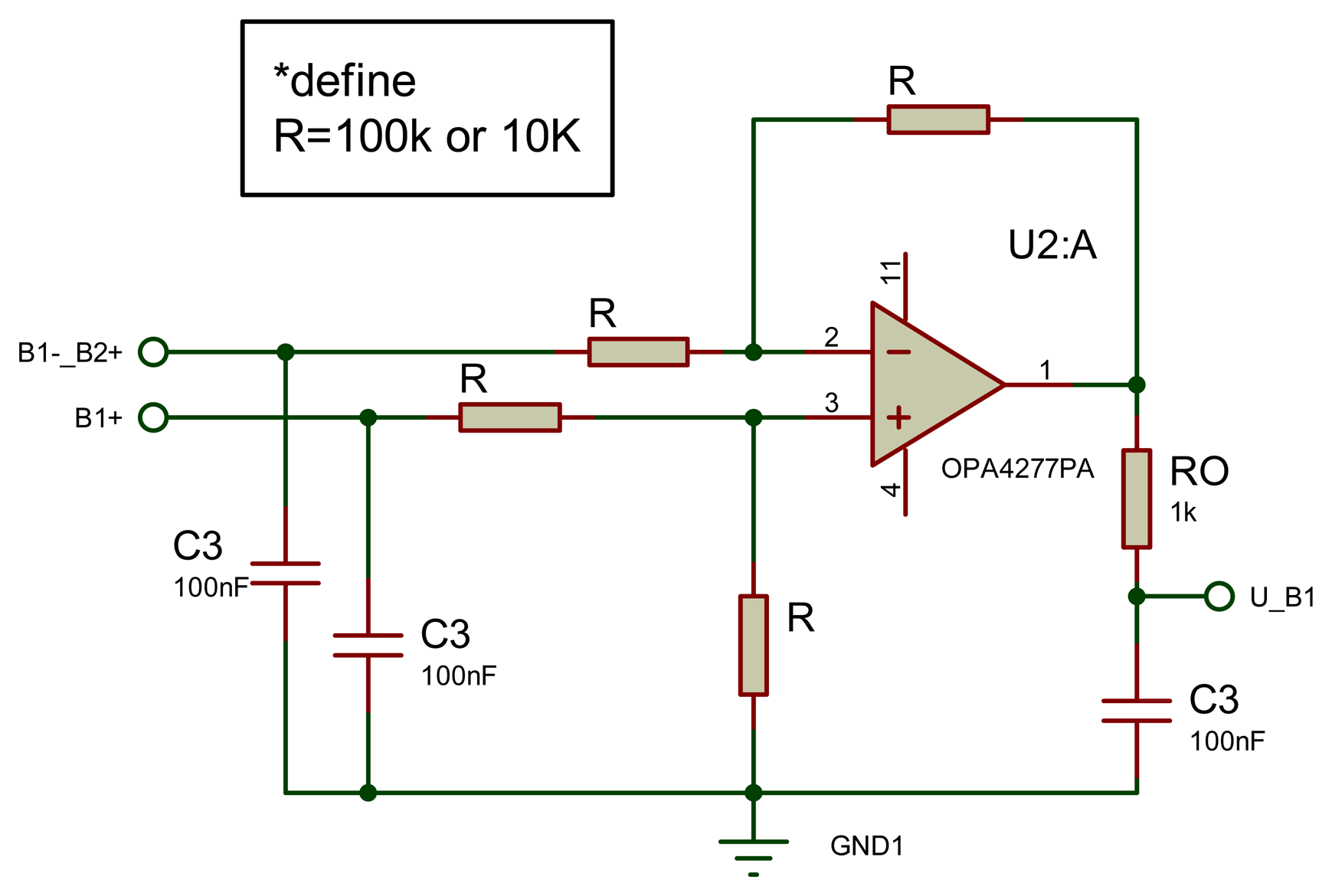
Cells voltage sensors are shown in Figure 19. The four cells' voltages are measured by using a differential method (except the second cell, which is connected directly to the microcontroller's ADC). A high precision operational amplifier “OPA4277PA”, with four op-amps inside is used for this purpose and its outputs is connected directly to microcontroller's ADC.
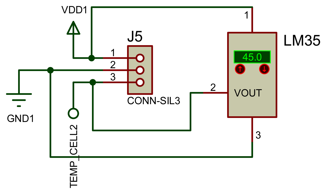
Temperature sensor is illustrated in Figure 20. Its connectors send a signal with 5 V to the thermometer “LM35DT”, as shown in Figure 20 and get the temperature value. They are four connectors to measure the four cells' temperatures.
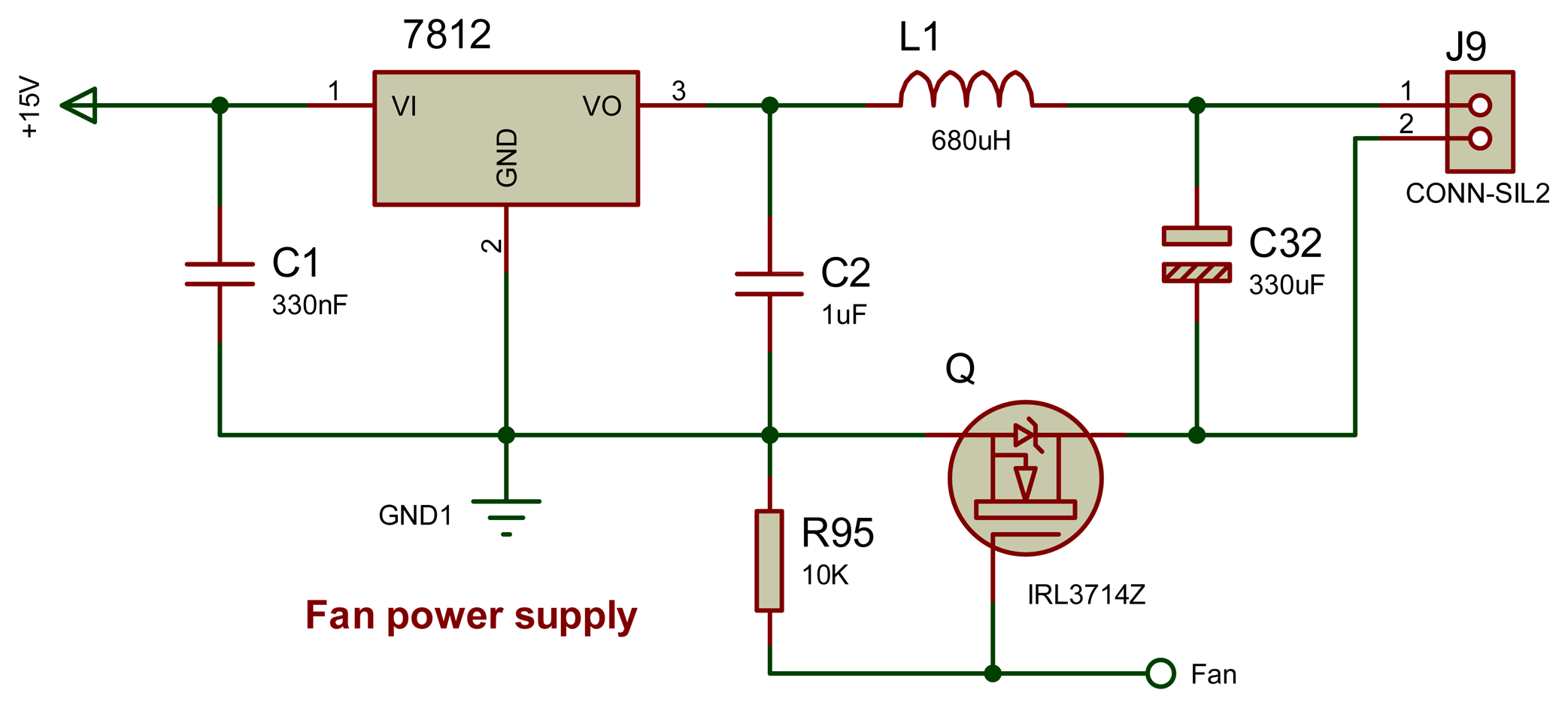
The power supply of the cooling fan and its speed control circuit are shown in Figure 21. The fan power supply utilizes a 12 V (7812) voltage regulator. The fan speed is controlled by PWM output from the slave microcontroller.
6.4. Implemented BC
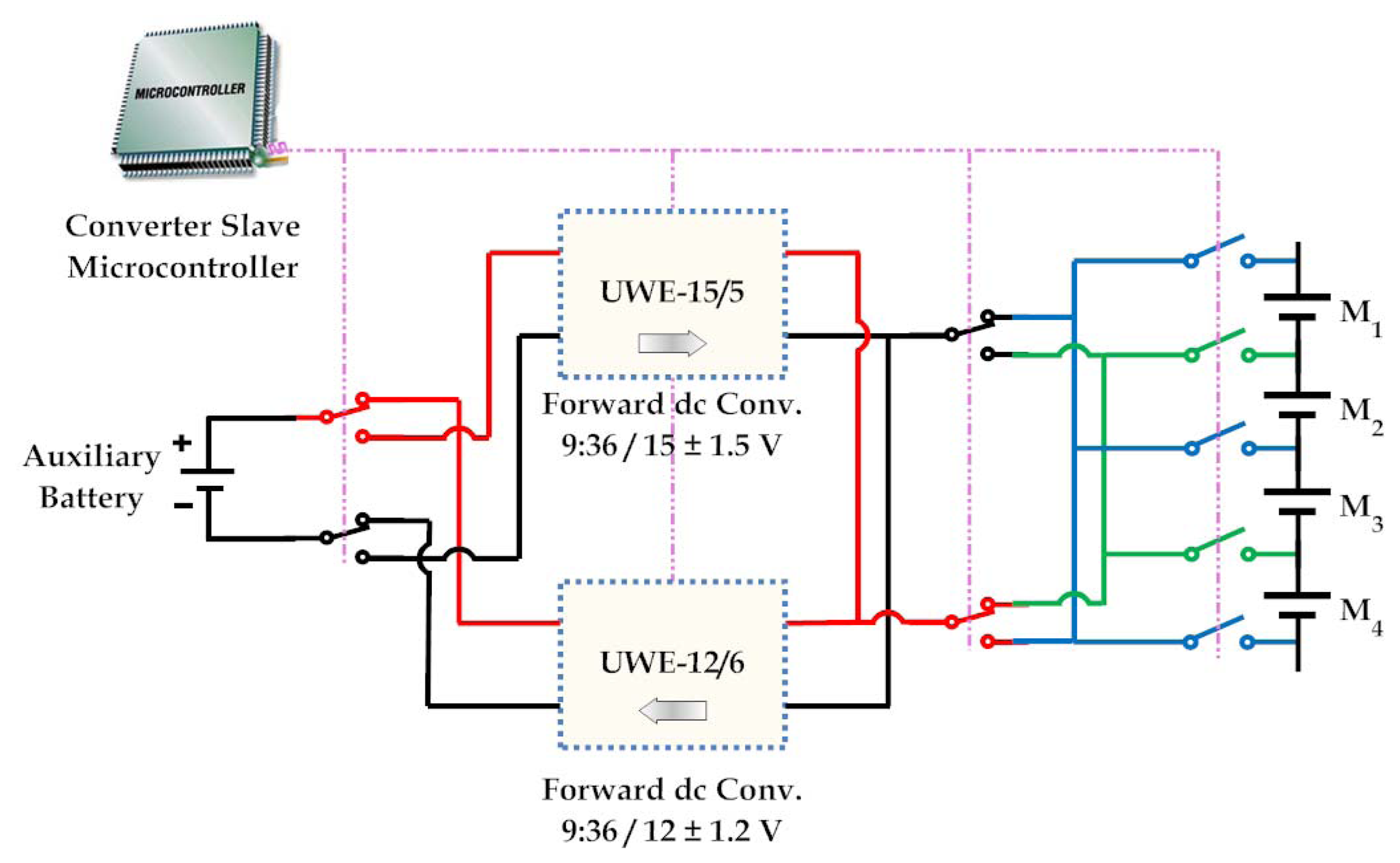
The balancing between the modules, as mentioned before is experimentally implemented by using two isolated forward converters modules “UWE-12/6” and “UWE-15/5” as is shown in Figure 22.
The simulation model of the two converters modules (UWE-12/6 and UWE-15/5) with their control circuit is simulated by using Proteus/ISIS program.
The MB, i.e., between the modules and through the AB, is implemented experimentally by using two forward converter modules “UWE-12/6” and “UWE-15/5”, as presented in Figure 23. The first converter module “UWE-12/6” has the properties of wide input voltage range (from 9 V to 36 V) and output voltage (12 ± 1.2 V) with 6 A rating. It is used for transferring the energy from the battery pack higher modules to the AB. The second converter module is “UWE-15/5”. It also has wide input voltage range as well (from 9 V to 36 V) and output voltage (15 ± 1.5 V) with 5 A rating. It is used for the reverse energy transfer from the AB to the battery pack lower module.
6.5. Master Control Circuit Experimental Implementation
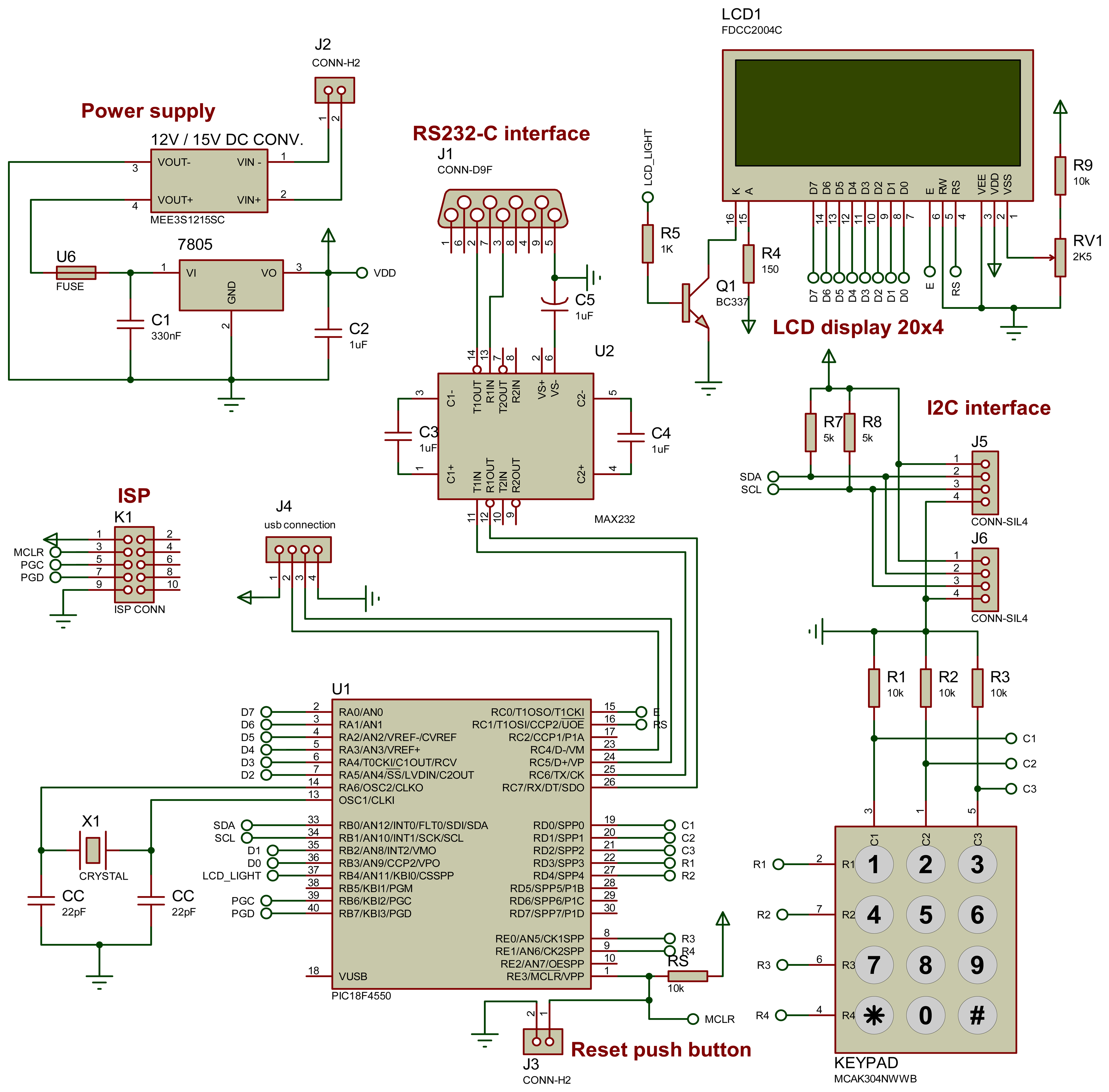
The simulation model of the master control circuit is designed by using the Proteus/ISIS program as shown in Figure 24. The master control circuit consists of:
The master microcontroller (PIC18F4550) with 20 MHz crystal.
Keypad and display screen, they are used for user interfacing.
The circuit ICs' power supply. It utilizes a 7805-voltage regulator.
I2C interfacing connectors to achieve the connection between the master and the slaves' microcontrollers.
RS232 interfacing for connecting the master microcontroller with the personal computer. It uses the “MAX232” dual EIA-232 drivers/receivers to adjust the voltage difference level between the microcontroller and the computer's RS232 port.
7. Experimental Results
This section presents the experimental results of the proposed modularization balancing prototype. These experimental tests are divided into two categories:
- 1st
results are obtained from the tests, which are carried out on two series LFP Li-Ion cells rated as 2.3 A·h capacities and 3.3 V nominal voltages. In these tests, the cells are balanced by using the SSC balancing system without modularization to observe the influences of the switching frequency, capacitor values, the cells voltage difference and the proposed boosting technique into the balancing performance.
- 2nd
experimental results are obtained based on the battery pack prototype of 12 Li-ion cells. The pack cells are defined with 20 A·h and 3.65 V each. This pack can be balanced using the modularized SSC balancing system. These results are obtained based on the SSC balancing without using the BC balancing and the SSC balancing operates with the BC MB.
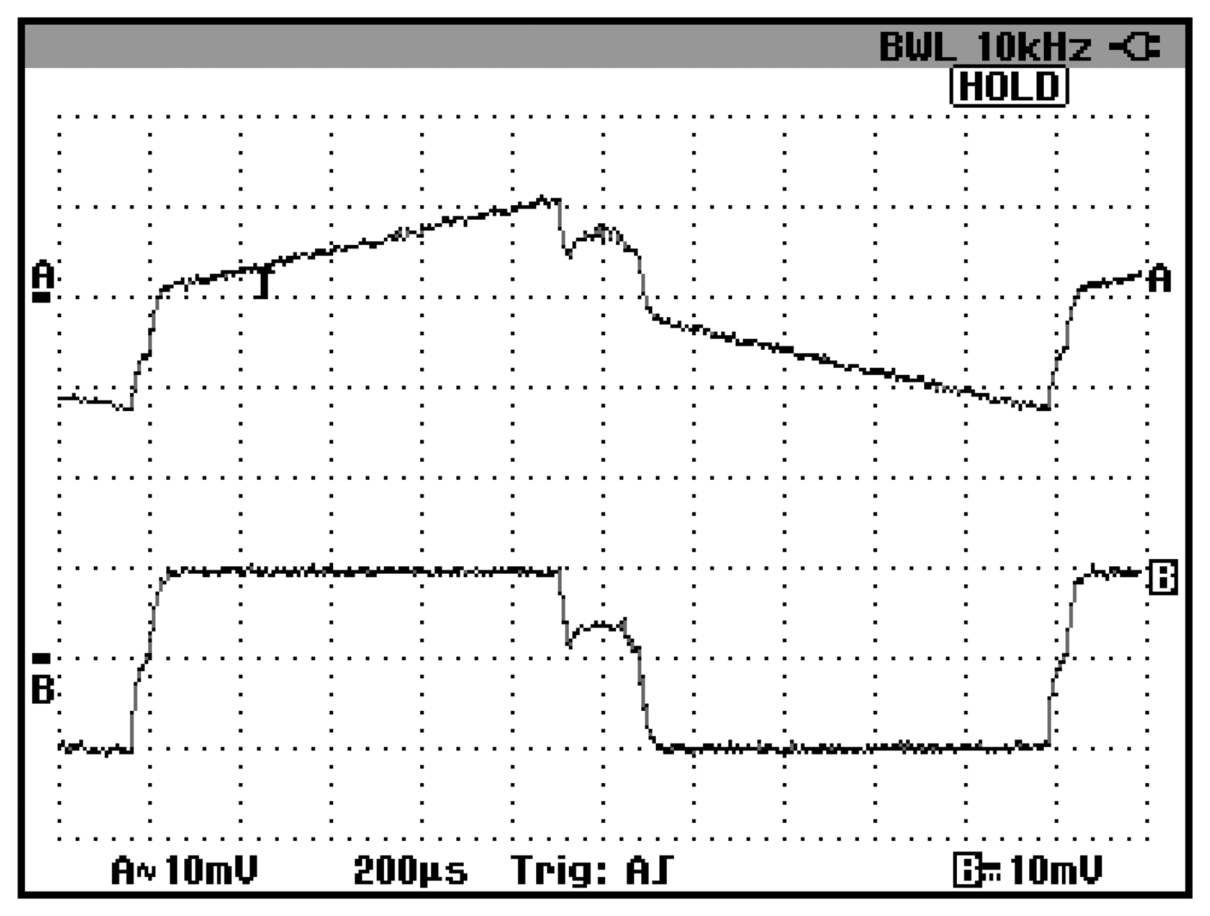
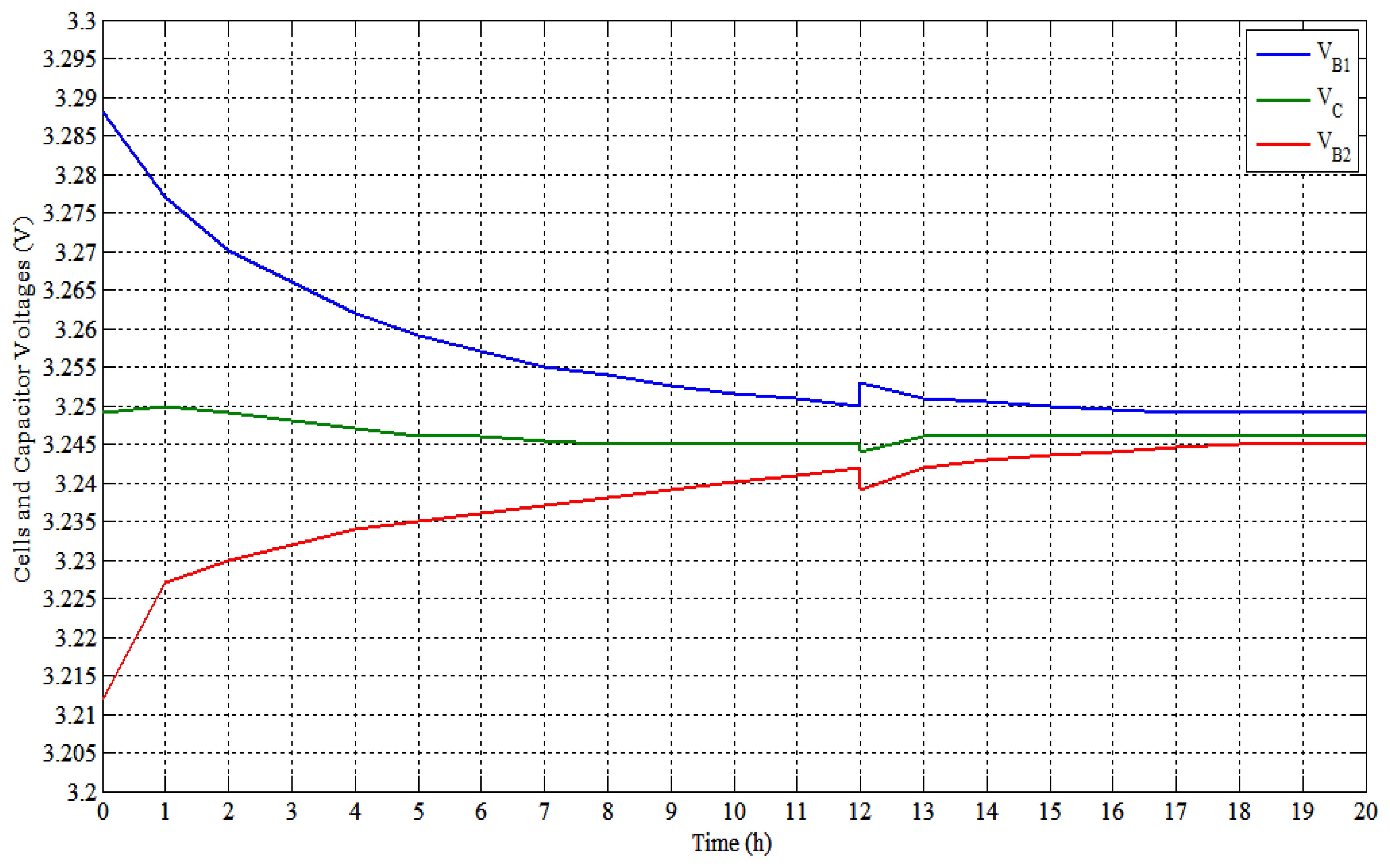
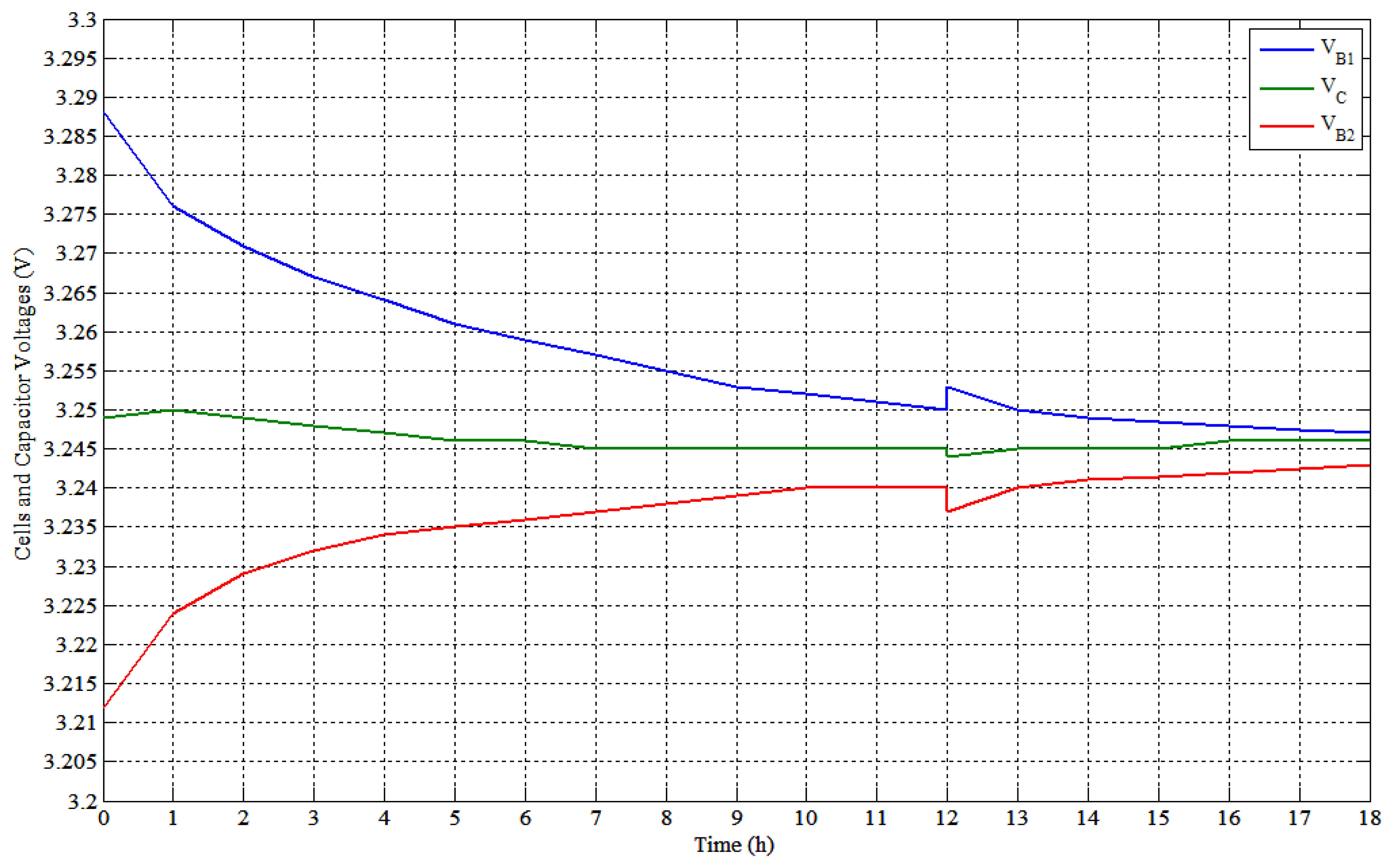
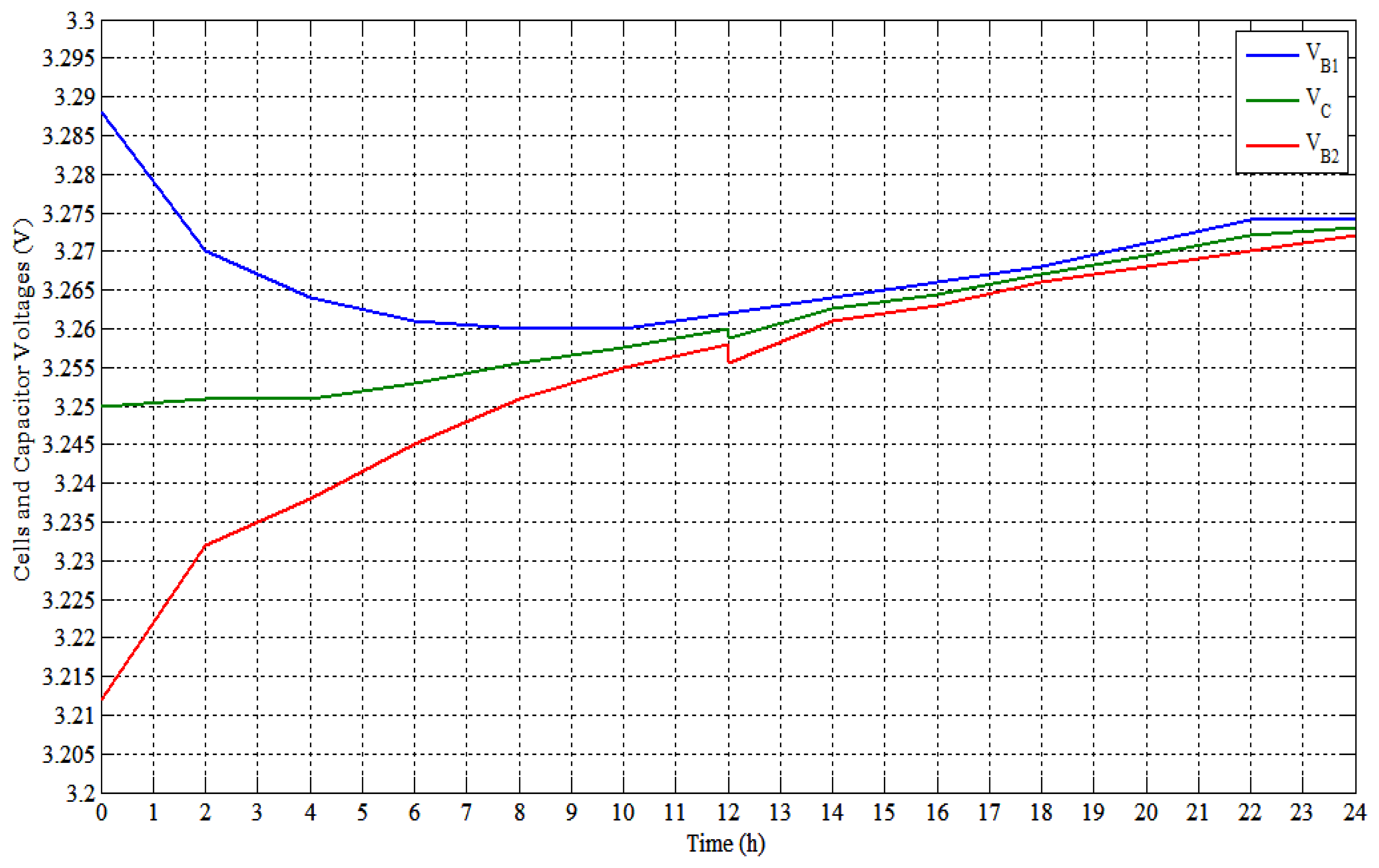
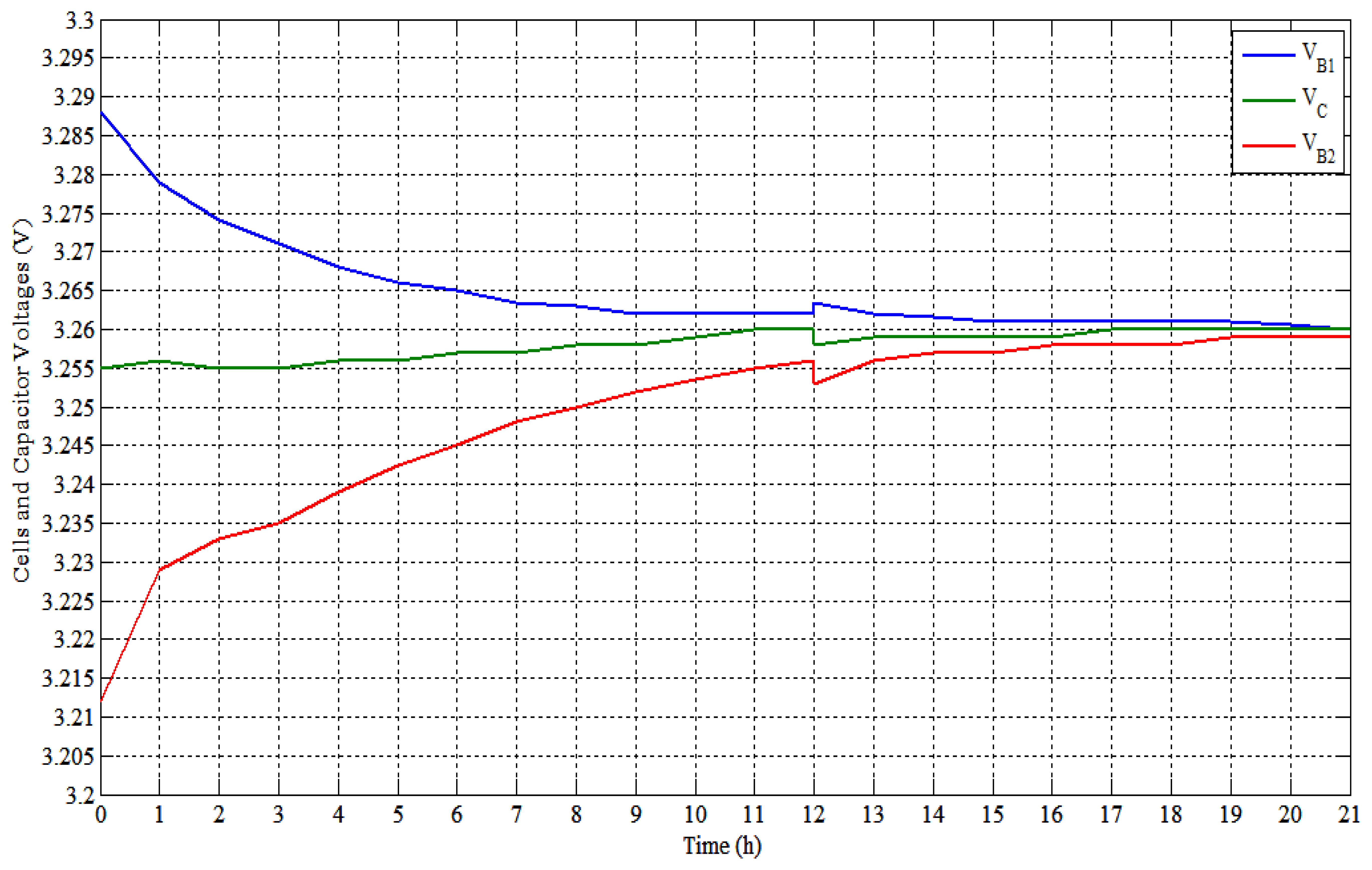
As a preliminary result, an experimental example of the capacitor behavior (voltage and current) during one microcontroller pulse pattern is shown in Figure 6. The charging, boosting and discharging with the rest periods of the capacitor voltage and current are shown in Figure 25.
In Figure 25, channel “A” is the capacitor voltage, while the capacitor current is represented by channel “B” (through 10 mΩ resistor). This example is captured at cells voltage difference about 750 mV.
7.1. Experimental Results on 2.3 A·h Cells
The 2.3 A·h cells' tests have been realized according to the following conditions and the summary given in Table 2:
The cells and the capacitor voltages are measured by using a Fluke “177” digital multimeter with an accuracy of ±0.09%. The multimeter measurements are taken every 1 h or 2 h according to the cell type.
Eight tests have been performed on these cells. The two cells are started with voltages of 3.288 V and 3.212 V (Vdiff. = 76 mV). The initial SoC of these cells are around 35% and 11.3%, respectively (SoC difference is around 23.7% or 545 mA·h).
The tests are performed by using open-loop control. Where the controller did not measure the cells' voltages. In other words, it is directly shuttling the energy between the two cells.
The time of tests is around 24 h so that there is a rest (nearly 12 h) after the first 12 h of balancing test.
The testing procedure is classified into three categories:
- (1)
The first category is carried out by using the same capacitor value with different switching frequency (Tests No. 1–3).
- (2)
The second category uses the same switching frequency with different capacitors value (Tests No. 3–5).
- (3)
The third balancing category is the proposed SSC control topology with the boosting technique (Tests No. 6–8).
The experimental Tests No. 6 and 8 have fixed boosting pulses of 250 μs and 40 μs, respectively. While the Test No. 7 has variable boosting pulses. The balancing is started the boosting pulse was 250 μs for 6 h. Then it decreases to 150 μs for another 6 h and finally the pulse was 50 μs till the end of the test.
Table 3 will gives more information and results summery of these tests.
As mentioned, the cells voltages were 3.288 V and 3.212 V (Vdiff. = 76 mV) before balance start, the SoCs were 35% and 11.3% (SoC difference is 23.7% or 545 mA·h) and the SoC summation was 46.3% (this is used as an indication of the total charges in the cells). Table 3 summarizes the previous experimental testing results.
Tables 2 and 3 summarize the preliminary eight tests. From these two tables it is easy to conclude the following:
From Tests No. 1–3 (Figures 26, 27 and 28) for the same capacitor value (22 mF) and variable switching frequency, the balancing speed is direct proportional with the switching frequency.
As can be seen in Tests No. 1–5, the minimum voltage difference is 4 mV. This voltage is obtained after very long time. In addition, Li-ion flat voltage region gives SoC difference around 8% according to the voltage difference (4 mV).
From Tests No. 3–5 (Figures 28, 29 and 30) for the same switching frequency and variable capacitor values, the balancing speed are direct proportional with the capacitor values. In addition, over a certain capacitor value (experimental found around 4.7 mF) the balancing time cannot be decreased any more.
The proposed SSC's control topology Tests No. 6–8 (Figures 31, 32 and 33) give the smallest voltage difference between the cells with the smallest balancing time. This small voltage difference can overcome LFP batteries flat voltage balancing problems.
The boosting pulse in Test No. 6 is large (250 μs) that makes the capacitor instant voltage becomes more than the higher cell voltage. It makes the capacitor charges and boosts the lower cell and the higher cell as well. It is clear in the cells final SoC summation, it will be higher than the normal balancing cases.
The boosting pulse in Test No. 7 (Figure 32) decreases along the test (from 250 μs to 50 μs) gathering with the cells voltage difference decrease. It improves the capacitor voltage behavior while the capacitor voltage not so high than the higher energy cell voltage. However, it takes longer balancing time than Test No. 6 (Figure 31).
The boosting pulse in Test No. 8 (Figure 33) is fixed and small enough along the test (40 μs). It makes the capacitor voltage during the boosting pulse sufficient to overcome the LFP Li-ion's flat voltage without receiving high-energy amount from the auxiliary source.
These tests give very small voltage difference between the cells. They are acceptable results, but the controller in these tests is switching between the two cells without measuring their voltages (open-loop). It means with the cells' voltages measurement, these voltage errors may be increased due to measurements errors. This case will be verified in the next experimental test where they are implemented in open-loop and closed-loop control.
By comparing Tests No. 2 and 8, they have the same capacitor value and the switching frequency. For the same final voltage differences (4 mV) the proposed SSC balancing system (Test No. 8) reaches it after 14 h and the normal SSC balancing achieved it after 20 h. That means the proposed SSC balancing reduces the balancing time by 30%.
By comparing Tests No. 2 and 8, the proposed SSC balancing system (Test No. 8) has a voltage difference of 1 mV after 19 h while the normal SSC balancing has a voltage difference of 4 mV till 24 h. The proposed SSC balancing has the minimum voltage difference.
7.2. Experimental Results on 20 A·h Cells Prototype
The second test category is carried out on the prototype of 20 A·h LiNiMnCoO2 Li-ion cells with total voltage of 43.8 V. The cells are balanced by using the proposed modularized SSC balancing system and the isolated bidirectional DC/DC converter (IBC). The tests results show the SSC balancing with and without the BC balancing.
These tests are performed using open and closed-loop control. During the closed-loop operation, the controller measures the cells voltage, selects the higher and lower cells, and shuttles the energy between these cells.
Now the prototype battery pack can be tested with the SSC balance gathering with the BC balance. Three experimental tests are performed on prototype battery pack:
- 1st
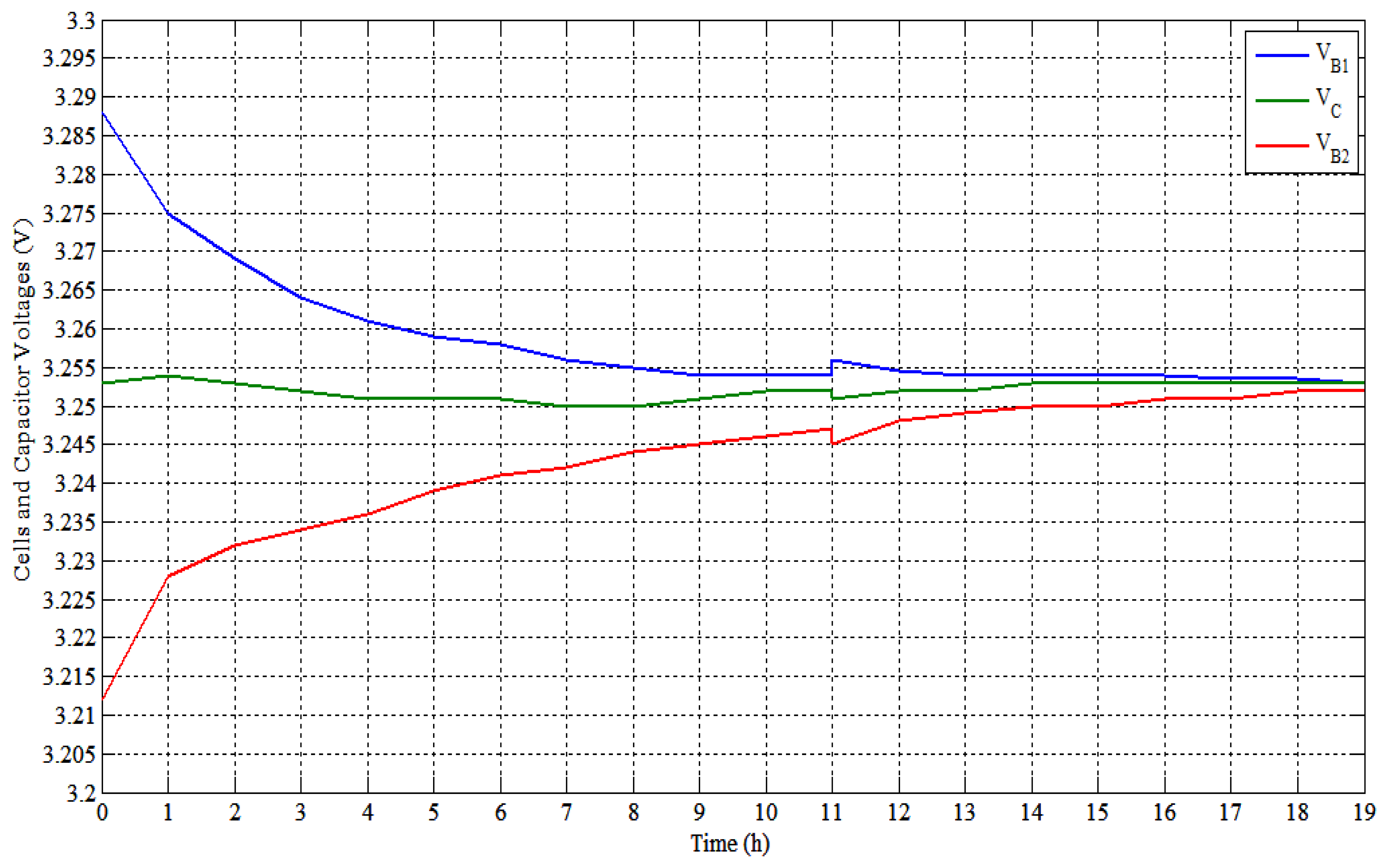
experiment is applied on two cells only as shown in Figure 34. The SSC balancing is utilized by using open-loop control strategy. In this case, the microcontroller is switching the capacitor between the two cells periodically.
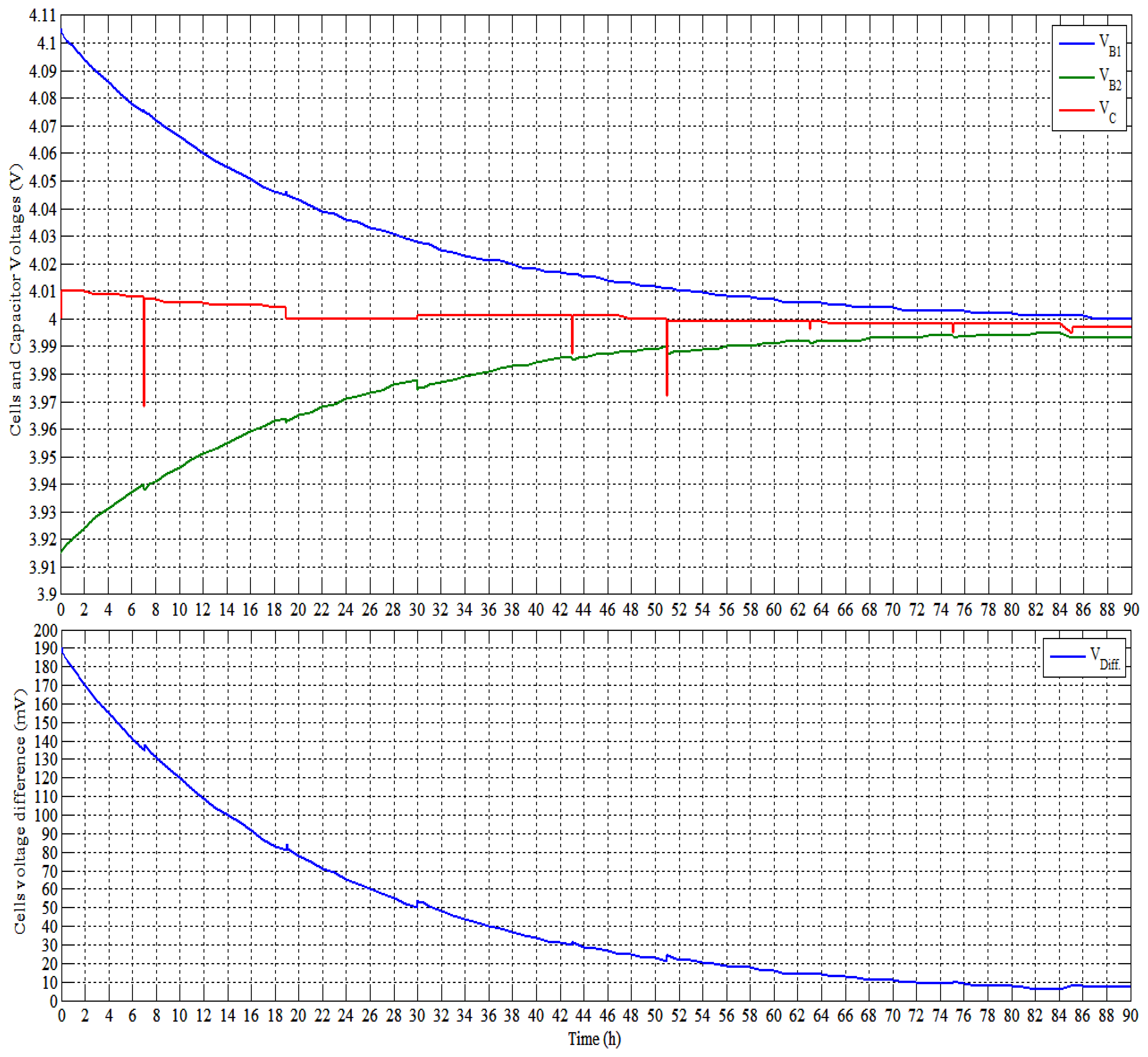
- 2nd
test uses the SSC balancing with closed-loop control (see Figure 35). The test will be performed on one module (four cells). The microcontroller measures the four cells voltages every 5 min, and then selecting the higher and the lower energy cells. After knowing the target cells, the microcontroller outputs the suitable on/off pulses into the corresponding switches to start the energy shuttling between the cells for 5 min. This test was done using the SSC balancing only and the BC balancing is turned off.
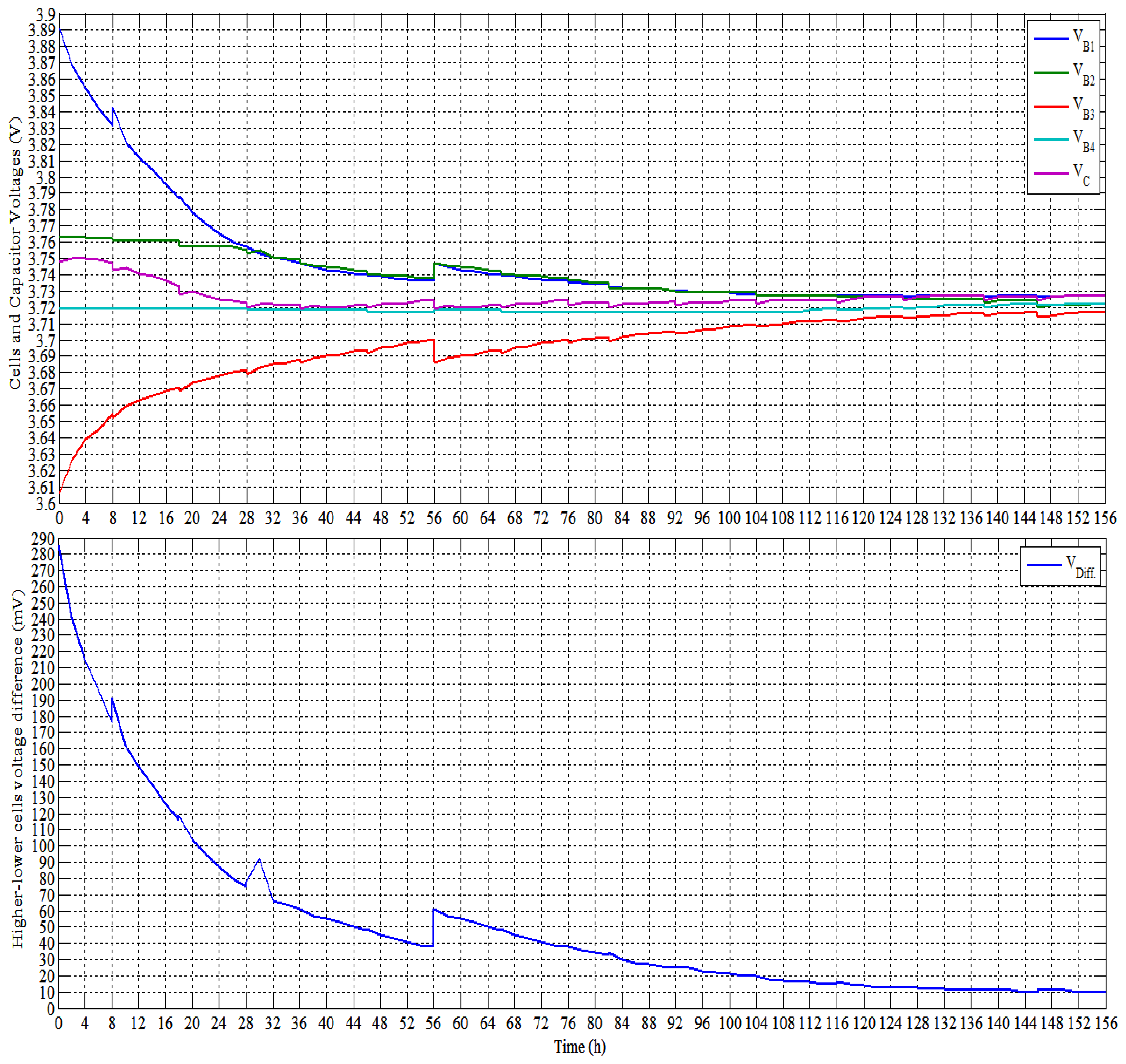
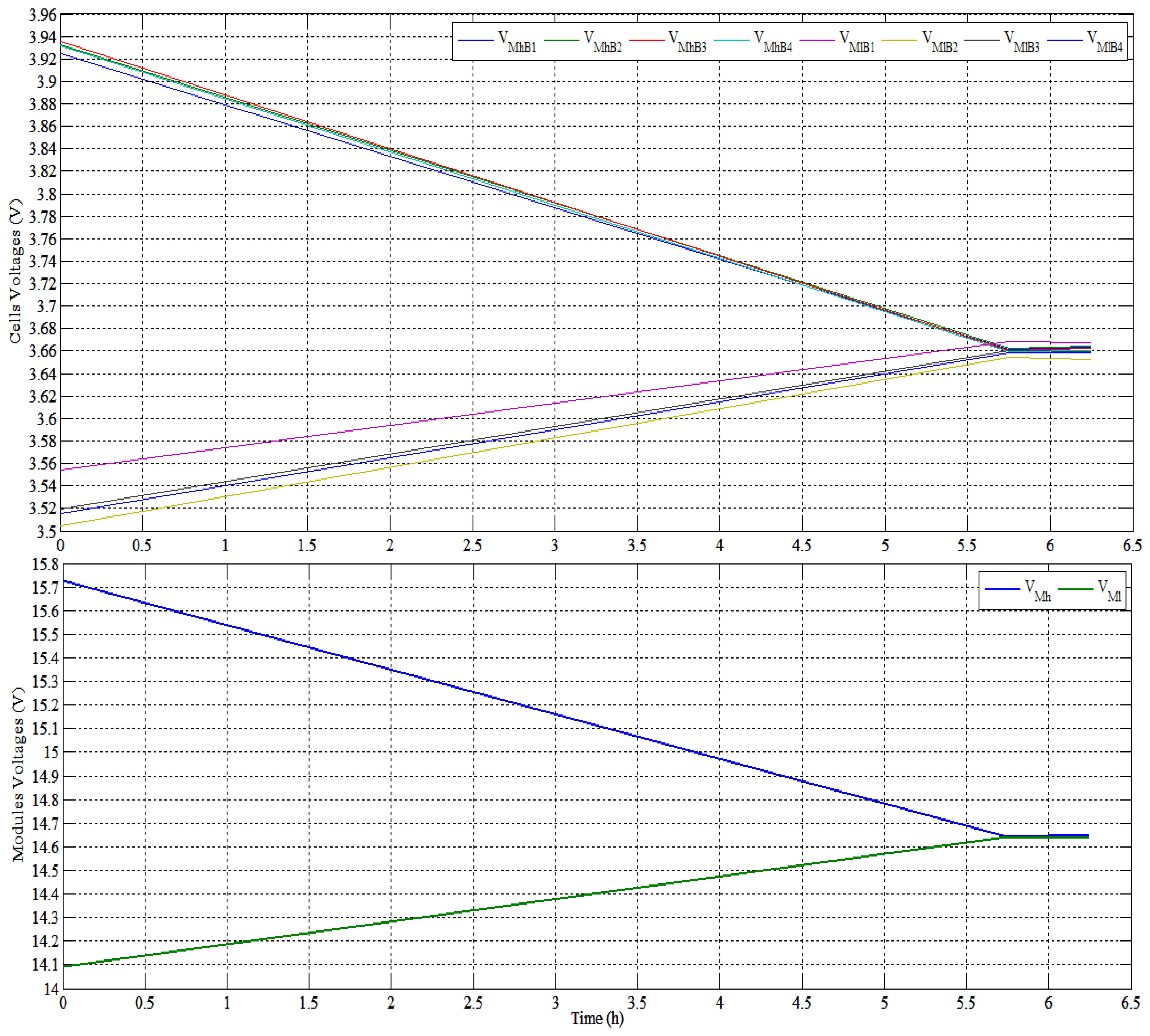
- 3rd
experimental test demonstrates the converter balancing between the modules as shown in Figure 36. In this test, the converter is shuttling energy between two modules through the AB. The converter connects the higher module into the AB using the converter UWE-12/6 for 5 min. Then it is connecting the AB into lower module using the converter UWE-15/5 for 5 min and so on till MB.
Due to long executed time of this test, the three tests are performed as; 12 operating hour balancing system then 12 h rest (rest due to night).
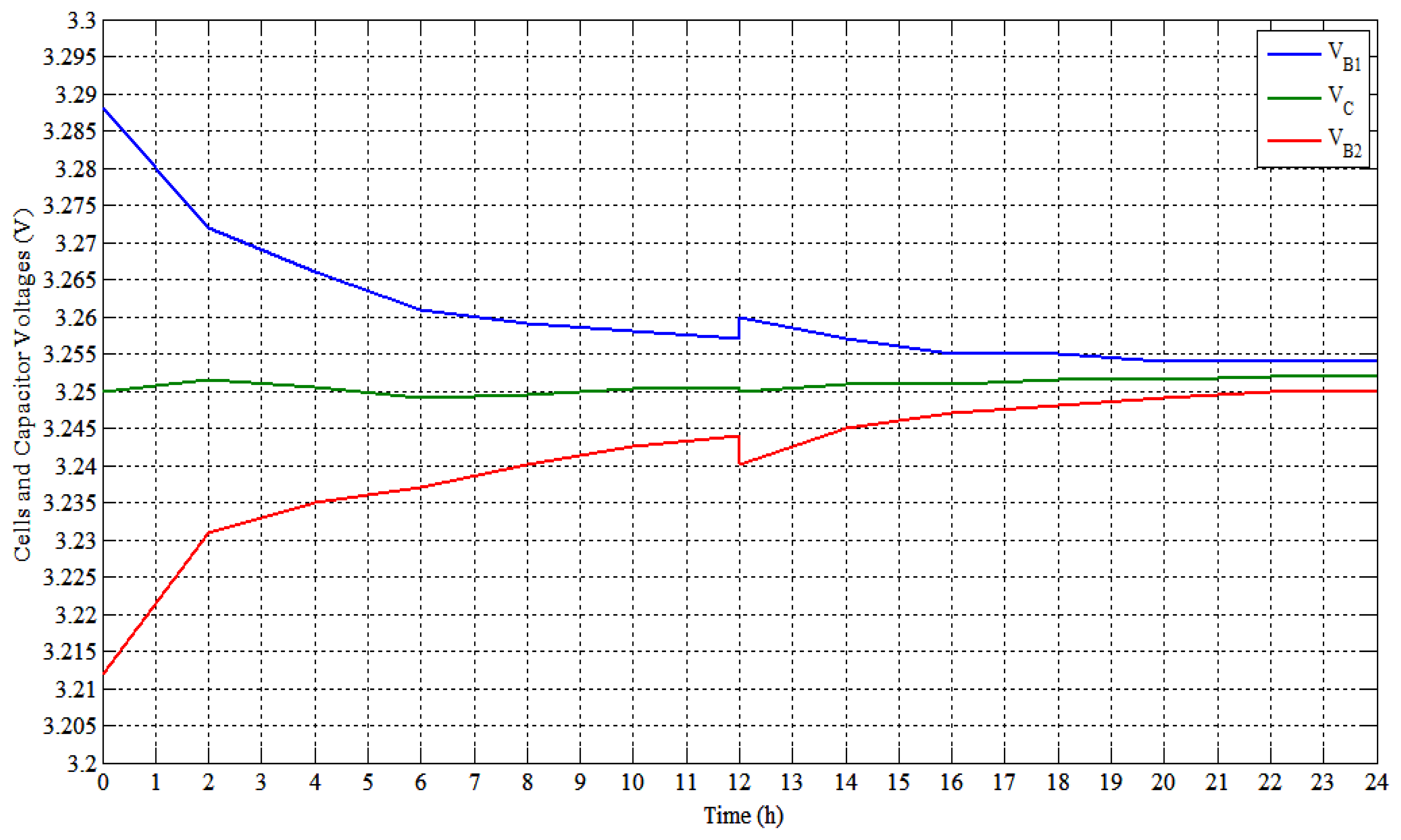
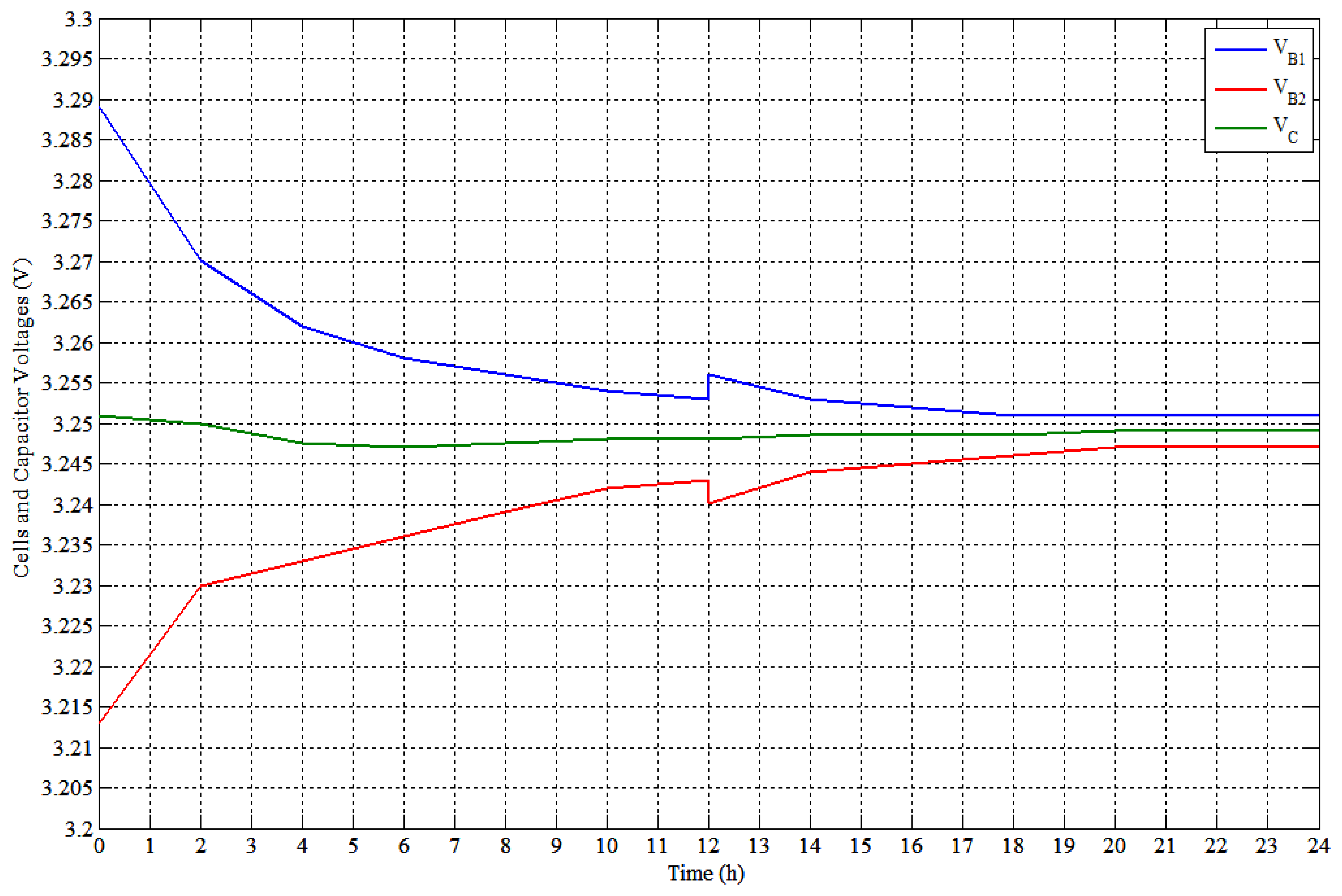
Some notes can be seen from Figure 34, which are:
- (1)
There are some notches in the capacitor voltage that are happened after the rest period (12 h), when the capacitor voltage is decreased to the low values.
- (2)
The cells voltages also change after the rest period. The higher cell's voltage is increased and the lower cell's voltage is decreased very little.
More comparison and details are given in Table 4.
Some notes on Figure 35:
- (1)
It is clear that the closed-loop control works well. In the beginning (first 28 h), the microcontroller is shuttling the energy between the Cells 2 and 4. From 28 h to 112 h, the cells (No. 1 and 2) are nearly equal, so that the controller is shuttling the energy between Cells 1 and 4, alternately with Cells 2 and 4. Form 112 h till the balancing is occurred; the controller is alternately changing between the all cells to have balance.
- (2)
The bottom part of Figure 35 gives the voltage difference between the higher and the lower energy cells.
Further comparison is shown in Table 4.
Some notes on Figure 36:
The top divisions of Figure 36 show the cells' voltage;
The bottom part of Figure 36 shows the two modules voltage.
From the previous three figures and Table 4, it can be concluded that:
The three tests are done with very high differences between the cells or the modules' SoC. This is done for studying the proposed balancing system along wide ranges of balance.
The first and the second tests took a long equalization time. Because of they have using the SSC balancing without the converter and mainly they should transfer huge amount of capacities e.g., 2 A·h and 10.94 A·h, respectively.
Open-loop control in test no. 1 gives maximum voltage difference of 7 mV at balancing. While the closed-loop control gives 10 mV maximum voltage differences. The difference in final voltages (3 mV) between the open and closed-loop control may be due to voltage measurements errors. In addition, these voltage differences can be smaller such as the 2.3 A·h cells tests results (1.5 mV or little more). But the tests need more time to reach these small differences because of the high capacity (20 A·h) cells.
Using large boosting pulse in Test No. 2 (110 μs) increases the energies summation of the cells at the end of balance.
The BC transfers a high amount of energy nearly 7.6 A·h (76% SoCdiff × 20 A·h/2) or 110.96 W·h in 5.75 h. It decreases the system balancing time significantly more than using the SSC balancing only.
The proposed balancing system can provide maximum voltage differences of 6 mV between cells and 12 mV (or less) between modules.
8. Proposed BMS with Modularized Balancing System Pricing
The proposed modularized system will divide the battery pack of 96 cells, 3.65 V and 20 A·h each into 12 modules (8 cells per module). Therefore, there will be nine slaves' microcontroller (8 for the SSC slaves and one slave for the converter) and one master microcontroller.
The battery pack has an average price of 9600 Euro (96 × 100є for the laboratory bought cells), i.e., the proposed BMS price is nearly 7.6% (734/9600) of the battery pack price.
The proposed battery system including the BMS components and prices are listed in Table 5.
9. Conclusions
The proposed balancing system with 12 cells battery pack has been simulated using the Simulink MATLAB® program environment for the system power circuits' simulation. In addition, the battery pack is also simulated using ISIS, part of the Proteus® program, for the system interfacing and control simulation.
Different simulations have been performed on the battery pack. Group of simulation have been tested into internal modules' balancing using the SSC without and with boosting technique, and MB using BC.
Two battery pack prototypes have been experimentally implemented. The first has 4 Li-ions cells with 2.3 A·h. It has been used to test the SSC balancing behavior with varying operating conditions (C, F & Vdiff.). The second prototype of 12 Li-ion cells (3 modules) with 20 A·h have has been realized experimentally. This prototype has represented the full-proposed BMS using SSC/IBC balancing, thermal management, charge/discharge control and input/output user interfacing.
The simulation models and the experimental prototypes have been discussed with systems in detail.
The simulation and experimental results proof the validity of the extracted transferred energy function, as well as, the proposed technique to control the balancing systems.
The proposed balancing system (SSC/IBC) gives good results during the system simulation and experimental tests. During the simulation, the system has 1 mV voltage difference between the module cells. For the experimental tests, the balancing system has a 1.5 mV (open-loop) maximum voltage difference between the cells for the 2.3 A·h cells. Moreover, it gives 7 mV to 10 mV for the 20 A·h cells during open and closed loop-control respectively.
A modularized balancing system implemented by adding the BC balancing decreases the SSC balancing time significantly. Approximate commercial BMS pricing for a complete battery pack is proposed.
Conflicts of Interest
The authors declare no conflict of interest.
References
- Daowd, M.; Omar, N.; van Den Bossche, P.; van Mierlo, J. A review of passive and active battery balancing based on Matlab/Simulink. Int. Rev. Electr. Eng. 2011, 6, 2974–2989. [Google Scholar]
- Daowd, M.; Omar, N.; van Den Bossche, P.; van Mierlo, J. Passive and Active Battery Balancing Comparison Based on Matlab Simulation. Proceedings of the 2011 IEEE Vehicle Power and Propulsion Conference (VPPC), Chicago IL, USA, 6–9 September 2011; pp. 1–7.
- Jian, C.; Schofield, N.; Emadi, A. Battery balancing methods: A Comprehensive Review. Proceedings of the IEEE Vehicle Power and Propulsion Conference, VPPC '08, Harbin, Heilongjiang, China, 3–5 September 2008; pp. 1–6.
- Kong, Z.-G.; Zhu, C.-B.; Lu, R.-G.; Cheng, S.-K. Comparison and Evaluation of Charge Equalization Technique for Series Connected Batteries. Proceedings of the 37th IEEE Power Electronics Specialists Conference PESC '06, Jeju, Korea, 18–22 June 2006; pp. 1–6.
- Moore, S.W.; Schneider, P.J. A review of Cell Equalization Methods for Lithium Ion and Lithium Polymer Battery Systems. Proceedings of the SAE 2001 World Congress, Detroit, MI, USA, 5–8 March 2001. [CrossRef]
- Isaacson, M.J.; Hollandsworth, R.P.; Giampaoli, P.J.; Linkowsky, F.A.; Salim, A.; Teofilo, V.L. Advanced Lithium Ion Battery Charger. Proceedings of the 15th Annual Battery Conference on Applications and Advances, Long Beach, CA, USA, 11–14 January 2000; pp. 193–198.
- Kutkut, N.H.; Divan, D.M. Dynamic Equalization Techniques for Series Battery Stacks. Proceedings of the 18th International Telecommunications Energy Conference, INTELEC '96, Boston, MA, USA, 6–10 October 1996; pp. 514–521.
- Lindemark, B. Individual Cell Voltage Equalizers (Ice) for Reliable Battery Performance. Proceedings of the 13th International Telecommunications Energy Conference, INTELEC '91, Kyoto, 5–8 November 1991; pp. 196–201.
- Stuart, T.A.; Wei, Z. Fast equalization for large lithium ion batteries. IEEE Aerosp. Electron. Syst. Mag. 2009, 24, 27–31. [Google Scholar]
- Zhang, X.; Liu, P.; Wang, D. The design and implementation of smart battery management system balance technology. J. Converg. Inf. Technol. 2011, 6, 108–116. [Google Scholar]
- Cadar, D.V.; Petreus, D.M.; Patarau, T.M. An Energy Converter Method for Battery Cell Balancing. Proceedings of the 2010 33rd International Spring Seminar on Electronics Technology (ISSE), Warsaw, Poland, 12–16 May 2010; pp. 290–293.
- Kobzev, G.A. Switched-Capacitor Systems for Battery Equalization. Proceedings of the VI International Scientific and Practical Conference of Students, Post-Graduates and Young Scientists, Modern Techniques and Technology, MTT 2000, Tomsk, Russia, 28 February–3 March 2000; pp. 57–59.
- Pascual, C.; Krein, P.T. Switched Capacitor System for Automatic Series Battery Equalization. Proceedings of the 12th Annual Applied Power Electronics Conference and Exposition, APEC '97, Atlanta, GA, USA, 23–27 February 1997; Volume 842, pp. 848–854.
- Speltino, C.; Stefanopoulou, A.; Fiengo, G. Cell Equalization in Battery Stacks through State of Charge Estimation Polling. Proceedings of the American Control Conference (ACC), Baltimore, MD, USA, 30 June–2 July 2010; pp. 5050–5055.
- Baughman, A.C.; Ferdowsi, M. Double-tiered switched-capacitor battery charge equalization technique. IEEE Trans. Ind. Electron. 2008, 55, 2277–2285. [Google Scholar]
- Baughman, A.; Ferdowsi, M. Double-Tiered Capacitive Shuttling Method for Balancing Series-Connected Batteries. Proceedings of the 2005 IEEE Conference on Vehicle Power and Propulsion, Chicago, IL, USA, 7–9 September 2005; pp. 109–113.
- Hong-Sun, P.; Chol-Ho, K.; Ki-Bum, P.; Gun-Woo, M.; Joong-Hui, L. Design of a charge equalizer based on battery modularization. IEEE Trans. Veh. Technol. 2009, 58, 3216–3223. [Google Scholar]
- Thanh Hai, P.; Crebier, J.; Chureau, A.; Collet, A.; van Nguyen, T. Optimized Structure for Next-to-Next Balancing of Series-Connected Lithium-Ion Cells. Proceedings of the 2011 26th Annual IEEE Applied Power Electronics Conference and Exposition (APEC), Fort Worth, TX, USA, 6–11 March 2011; pp. 1374–1381.
- Sang-Hyun, P.; Tae-Sung, K.; Jin-Sik, P.; Gun-Woo, M.; Myung-Joong, Y. A New Battery Equalizer Based on Buck-Boost Topology. Proceedings of the 7th Internatonal Conference on Power Electronics, ICPE '07, Daegu, Korea, 22–26 October 2007; pp. 962–965.
- Moo, C.S.; Hsieh, Y.C.; Tsai, I.S.; Cheng, J.C. Dynamic charge equalisation for series-connected batteries. IEE Proc. Electr. Power Appl. 2003, 150, 501–505. [Google Scholar]
- Imtiaz, A.M.; Khan, F.H.; Kamath, H. A Low-Cost Time Shared Cell Balancing Technique for Future Lithium-Ion Battery Storage System Featuring Regenerative Energy Distribution. Proceedings of the 2011 26th Annual IEEE Applied Power Electronics Conference and Exposition (APEC), Fort Worth, TX, USA, 6–11 March 2011; pp. 792–799.
- Jong-Won, S.; Gab-Su, S.; Chang-Yoon, C.; Bo-Hyung, C. Selective Flyback Balancing Circuit with Improved Balancing Speed For Series Connected Lithium-Ion Batteries. Proceedings of the 2010 International Power Electronics Conference (IPEC), Sapporo, Japan, 21–24 June 2010; pp. 1180–1184.
- Einhorn, M.; Roessler, W.; Fleig, J. Improved performance of serially connected li-ion batteries with active cell balancing in electric vehicles. IEEE Trans. Veh. Technol. 2011, 60, 2448–2457. [Google Scholar]
- Parky, K.-H.; Kim, C.-H.; Cho, H.-K.; Seo, J.-K. Design considerations of a lithium ion battery management system (BMS) for the STSAT-3 satellite. J. Power Electron. 2010, 10, 210–217. [Google Scholar]
- Hong-Sun, P.; Chong-Eun, K.; Chol-Ho, K.; Gun-Woo, M.; Joong-Hui, L. A modularized charge equalizer for an HEV lithium-ion battery string. IEEE Trans. Ind. Electron. 2009, 56, 1464–1476. [Google Scholar]
- Yan, J.; Cheng, Z.; Xu, G.; Qian, H.; Xu, Y. Fuzzy Control for Battery Equalization Based on State of Charge. Proceedings of the IEEE 72nd Vehicular Technology Conference Fall (VTC 2010-Fall), Ottawa, ON, Canada, 6–9 September 2010; pp. 1–7.
- Yuang-Shung, L.; Chun-Yi, D.; Guo-Tian, C.; Shen-Ching, Y. Battery Equalization Using Bi-Directional Cuk Converter in DCVM Operation. Proceedings of the IEEE 36th Power Electronics Specialists Conference, PESC '05, Recife, Brazil, 12–16 June 2005; pp. 765–771.
- Wei, H.; Kong-Soon, N.; Jin-Hsin, H.; Chin-Sien, M. Charge Equalization of Battery Power Modules in Series. Proceedings of the 2010 International Power Electronics Conference (IPEC), 21–24 June 2010; pp. 1568–1572.
- Chin-Sien, M.; Kong Soon, N.; Yao-Ching, H. Parallel operation of battery power modules. IEEE Trans. Energy Convers. 2008, 23, 701–707. [Google Scholar]
- Chol-Ho, K.; Hong-Sun, P.; Chong-Eun, K.; Gun-Woo, M.; Joong-Hui, L.; Jeon Keun, O. Charge Equalization Converter with Parallel Primary Winding for Series Connected Lithium-Ion Battery Strings in HEV. Proceedings of the 7th Internatonal Conference on Power Electronics, ICPE '07, Daegu, Korea, 22–26 October 2007; pp. 795–800.
- Kim, C.-H.; Park, H.-S.; Kim, C.-E.; Moon, G.-W.; Lee, J.-H. Individual charge equalization converter with parallel primary winding of transformer for series connected lithium-ion battery strings in an HEV. J. Power Electron. 2009, 9, 472–480. [Google Scholar]
- Chakraborty, S.; Jain, A.K.; Mohan, N. Novel Converter Topology and Algorithm for Simultaneous Charging and Individual Cell Balancing of Multiple Li-Ion Batteries. Proceedings of the 26th Annual International Telecommunications Energy Conference, INTELEC 2004, Chicago, IL, USA, 19–23 September 2004; pp. 248–253.
- Yuang-Shung, L.; Cheng-En, T.; Yi-Pin, K.; Ming-Wang, C. Charge equalization Using Quasi-Resonant Converters in Battery String for Medical Power Operated Vehicle Application. Proceedings of the 2010 International Power Electronics Conference (IPEC), Sapporo, Japan, 21–24 June 2010; pp. 2722–2728.
- Lee, Y.S.; Cheng, G.T. Quasi-resonant zero-current-switching bidirectional converter for battery equalization applications. IEEE Trans. Power Electron. 2006, 21, 1213–1224. [Google Scholar]
- Maharjan, L.; Inoue, S.; Akagi, H.; Asakura, J. State-of-charge (SOC)-balancing control of a battery energy storage system based on a cascade PWM converter. IEEE Trans. Power Electron. 2009, 24, 1628–1636. [Google Scholar]
- Gottwald, T.; Ye, Z.; Stuart, T. Equalization of EV and HEV batteries with a ramp converter. IEEE Trans. Aerosp. Electron. Syst. 1997, 33, 307–312. [Google Scholar]
- Bentley, W.F. Cell Balancing Considerations for Lithium-Ion Battery Systems. Proceedings of the 12th Annual Battery Conference on Applications and Advances, Long Beach, CA, USA, 14–17 January 1997; pp. 223–226.
- Daowd, M.; Omar, N.; Van Den Bossche, P.; Van Mierlo, J. Capacitor Based Battery Balancing System. Proceedings of the 26th Hybrid and Fuel Cell Electric Vehicle Symposium (EVS-26), Los Angeles, CA, USA, 6–9 May 2012; pp. 1–9.
- Daowd, M.; Antoine, M.; Omar, N.; van Den Bossche, P.; van Mierlo, J. Single switched capacitor battery balancing system enhancements. Energies 2013, 6, 2149–2174. [Google Scholar]
- Van Mierlo, J. Simulation Software for Comparison and Design of Electric, Hybrid Electric and Internal Combustion Vehicles with Respect to Energy, Emissions and Performances. Ph.D. Thesis, Vrije Universiteit Brussel, Brussel, Belgium, 2000. [Google Scholar]
- Van Mierlo, J.; Maggetto, G. Vehicle simulation program: A tool to evaluate hybrid power management strategies based on an innovative iteration algorithm. Proc. Inst. Mech. Eng. Part D J. Automob. Eng. 2001, 215, 1043–1052. [Google Scholar]
- Van Mierlo, J.; Maggetto, G.; van de Burgwal, E.; Gense, R. Driving style and traffic measures—Influence on vehicle emissions and fuel consumption. Proc. Inst. Mech. Eng. Part D J. Automob. Eng. 2004, 218, 43–50. [Google Scholar]
- Omar, N.; Verbrugge, B.; Mulder, G.; van Den Bossche, P.; van Mierlo, J.; Daowd, M.; Dhaens, M.; Pauwels, S. Evaluation of Performance Characteristics of Various Lithium-Ion Batteries for Use in BEV Application. Proceedings of the 2010 IEEE Vehicle Power and Propulsion Conference (VPPC), Lille, France, 1–3 September 2010; pp. 1–6.
- Omar, N.; Daowd, M.; Verbrugge, B.; Mulder, G.; van Den Bossche, P.; van Mierlo, J.; Dhaens, M.; Pauwels, S.; Leemans, F. Assessment of Performance Characteristics of Lithium-Ion Batteries for PHEV Vehicles Applications Based on a Newly Test Methodology. Proceedings of the 25th Electric Vehicle Symposium (EVS-25), Shenzhen, Guangdong, China, 5–9 November 2010.
- Omar, N.; Daowd, M.; Hegazy, O.; Geukens, B.; Timmermans, J.-M.; Coosemans, T.C.; van Den Bossche, P.; van Mierlo, J. Assessment of second life of lithium iron phosphate based batteries. Int. Rev. Electr. Eng. 2012, 7, 3941–3948. [Google Scholar]
- Omar, N.; Daowd, M.; Hegazy, O.; Mulder, G.; Timmermans, J.-M.; Coosemans, T.; van Den Bossche, P.; van Mierlo, J. Standardization work for BEV and HEV applications: Critical appraisal of recent traction battery documents. Energies 2012, 5, 138–156. [Google Scholar]
- Omar, N.; Daowd, M.; van Den Bossche, P.; Hegazy, O.; Smekens, J.; Coosemans, T.; van Mierlo, J. Rechargeable energy storage systems for plug-in hybrid electric vehicles—Assessment of electrical characteristics. Energies 2012, 5, 2952–2988. [Google Scholar]
- Pattipati, B.; Sankavaram, C.; Pattipati, K. System identification and estimation framework for pivotal automotive battery management system characteristics. IEEE Trans. Syst. Man Cybern. Part C Appl. Rev. 2011, 41, 869–884. [Google Scholar]
- Daowd, M. Intelligent Battery Management System. Ph.D. Thesis, Vrije Universiteit Brussel, Brussel, Belgium, 2013. [Google Scholar]
- Plett, G.L. Extended Kalman filtering for battery management systems of LiPB-based HEV battery packs: Part 3. State and parameter estimation. J. Power Sources 2004, 134, 277–292. [Google Scholar]
- Sun, F.; Hu, X.; Zou, Y.; Li, S. Adaptive unscented Kalman filtering for state of charge estimation of a lithium-ion battery for electric vehicles. Energy 2011, 36, 3531–3540. [Google Scholar]
- Rezvanizaniani, S.M.; Liu, Z.; Chen, Y.; Lee, J. Review and recent advances in battery health monitoring and prognostics technologies for electric vehicle (EV) safety and mobility. J. Power Sources 2014, 256, 110–124. [Google Scholar]
- Hu, X.; Li, S.E.; Jia, Z.; Egardt, B. Enhanced sample entropy-based health management of Li-ion battery for electrified vehicles. Energy 2014, 64, 953–960. [Google Scholar]
- Eddahech, A.; Briat, O.; Woirgard, E.; Vinassa, J.M. Remaining useful life prediction of lithium batteries in calendar ageing for automotive applications. Microelectron. Reliab. 2012, 52, 2438–2442. [Google Scholar]
- Karnjanapiboon, C.; Jirasereeamornkul, K.; Monyakul, V. Charge Equalized Module for Serially Connected VRLA Battery String Using Quasi-Resonant Flyback Converter. Proceedings of the 2010 5th IEEE Conference on Industrial Electronics and Applications (ICIEA), Taichung, Taiwan, 15–17 June 2010; pp. 2148–2153.
- Samosir, A.S.; Yatim, A. Dynamic Evolution Control of Bidirectional DC-DC Converter for Interfacing Ultracapacitor Energy Storage to Fuel Cell Electric Vehicle System. Proceedings of the Australasian Universities Power Engineering Conference, AUPEC '08, Sydney, Australia, 14–17 December 2008; pp. 1–6.
- Samosir, A.S.; Yatim, A.H.M. Implementation of dynamic evolution control of bidirectional DC-DC converter for interfacing ultracapacitor energy storage to fuel-cell system. IEEE Trans. Veh. Technol. 2010, 57, 3468–3473. [Google Scholar]
- Murata Power Solutions (MURATA-PS). The UWE Series “Eighth-Brick” DC-DC Converters are High-Current Isolated Power Modules Designed for Use in High-Density System Boards. Available online: http://www.murata-ps.com/data/power/uwe.pdf (accessed on 15 October 2012).
Abbreviations or Glossary
| AB | Auxiliary battery |
| BC | Bidirectional DC/DC converter |
| BMSs | Battery management systems |
| BP | Battery pack |
| DTSC | Double-tiered switched capacitor balancing |
| EV | Electric vehicle |
| EPNGV | Extended partnership for a new generation of vehicles |
| IBC | Isolated bidirectional DC/DC converter |
| IMB | Inside module balancing |
| Li-ion | Lithium-ion |
| LFP | Lithium iron phosphate |
| Li-Po | Lithium-polymer |
| MB | Module balancing |
| MSC | Modularized switched capacitor balancing |
| PWM | Pulse width modulation |
| RUL | Remaining useful life |
| SC | Switched capacitor |
| SoC | State of charge (%) |
| SoH | State of health (%) |
| SSC | Single switched capacitor |


| Points of comparison | SSC without boosting | SSC/BC |
|---|---|---|
| Modules maximum SoC differences at t = 0 (M1, M2, M3)% | 15, 15, 15 | 15, 15, 15 |
| Modules maximum SoC differences at t = 2.75 h (M1, M2, M3)% | 8, 14, 7 | 12, 13, 12 |
| Modules maximum SoC differences at t = 12 h (M1, M2, M3)% | 3, 12, 1.5 | Not available |
| Balancing time (h) M1, M2, M3 | 7.5, NO *, 4.5 | Not available |
| Initial energies summation (W·h) M1, M2, M3 & M1 + M2 + M3 | 22.1, 16, 9.8 & 47.94 | 22.1, 16, 9.8 & 47.94 + 353 (AB) |
| Energies summation at t = 2.75 h (W·h) M1, M2, M3 & M1 + M2 + M3 | 22.1, 16, 9.8 & 47.94 | 16.65, 16, 16.65 & 49.3 + 348.5 (AB) |
| Final energies summation (W·h) M1, M2, M3 & M1 + M2 + M3 | 22.1, 16, 9.8 & 47.93 | Not available |
| Total energy losses at 2.75 h (W·h) | 0.01 | 3.14 |
| System efficiency (%) | 99.98 | 99.2 |
*Balance not occurred for the second module cells till end of test, 12 h.
| Test No. | C (mF) | F (Hz) | Boosting pulse (μs) | T divisions (μs): higher cell-off-lower cell-off | |
|---|---|---|---|---|---|
| Variable F & C | 1 | 22 | 83 | - | 5800-200-5800-200 |
| 2 | 22 | 588 | - | 800-50-800-50 | |
| 3 | 22 | 2000 | - | 200-50-200-50 | |
| 4 | 4.7 | 2000 | - | 200-50-200-50 | |
| 5 | 0.47 | 2000 | - | 200-50-200-50 | |
| Boosting technique | 6 | 22 | 83 | 250 | 5800-50_250_50-5800-50 |
| 7 | 22 | 83 | 250-150-50 | 5800-50_tBoost_50-5800-50 | |
| 8 | 22 | 588 | 40 | 800-20_40_20-800-20 | |
| Test No. | C (mF) | F (Hz) | Balancing time (h) | OCV @ balance | SoC @ balance | Notes | |||||
|---|---|---|---|---|---|---|---|---|---|---|---|
| Cell 1 (V) | Cell 2 (V) | Diff. (mV) | Cell 1 (%) | Cell 2 (%) | Diff. (%) | Sum (%) | |||||
| 1 | 22 | 83 | 22 | 3.254 | 3.25 | 4 | 23.5 | 22.1 | 1.4 | 45.6 | 4 mV till 24 h |
| 2 | 22 | 588 | 20 | 3.251 | 3.247 | 4 | 22.5 | 21.3 | 1.2 | 43.8 | 4 mV till 24 h |
| 3 | 22 | 2000 | 17.5 | 3.249 | 3.245 | 4 | 21.9 | 20.6 | 1.3 | 42.5 | 4 mV till 20 h |
| 4 | 4.7 | 2000 | 18 | 3.247 | 3.243 | 4 | 21.3 | 19.9 | 1.4 | 41.2 | - |
| 5 | 0.47 | 2000 | 19 | 3.246 | 3.242 | 4 | 21 | 19.6 | 1.4 | 40.6 | - |
| 6 | 22 | 83 | 24 | 3.274 | 3.272 | 2 | 30.8 | 30.2 | 0.6 | 61 | 4 mV @ 13 h |
| 7 | 22 | 83 | 21 | 3.26 | 3.259 | 1 | 25.7 | 25.2 | 0.5 | 50.9 | 4 mV @ 15 h |
| 8 | 22 | 588 | 19 | 3.253 | 3.252 | 1 | 23.2 | 22.9 | 0.3 | 46.1 | 4 mV @ 14 h |
| Experiment comparison | Test No. 1: SSC open-loop | Test No. 2: SSC closed-loop | Test No. 3: converter |
|---|---|---|---|
| C (mf) | 100 | 100 | - |
| F (Hz) | 500 | 500 | - |
| Boosting pulse (μs) | 50 | 110 | - |
| Balancing time (h) | 90 | 156 | 5.65 |
| Initial OCVs (V) | 4.105, 3.915 | 3.891, 3.763, 3.720, 3.606 | M1 = 3.925 + 3.933 + 3.936 + 3.932; M2 = 3.554 + 3.504 + 3.519 + 3.515; M1 = 15.726, M2 = 14.092 |
| Final OCVs (V) | 4.000, 3.993 | 3.727, 3.722, 3.723, 3.717 | M1 = 3.663 + 3.664 + 3.662 + 3.660; M2 = 3.667 + 3.653 + 3.659 + 3.658; M1 = 14.649, M2 = 14.637 |
| Initial OCVs Diff. (mV) | 190 | 128, 43, 114 (total = 285) | 1634 |
| Final OCVs Diff. (mV) | 7 | 5, −1, 6 (total = 10) | 12 |
| Initial SoCs (%) | 96.7, 76.7 | 73.8, 58.5, 51.2 18.5 | M1 = 77.9, 79, 79.3, 78.8; M2 = 7.6, 0, 2, 1.2 |
| Final SoCs (%) | 86.5, 85.8 | 53, 51.4, 51.8, 50.8 | M1 = 33.8, 34.2, 33.3, 32.7; M2 = 35.4, 30.1, 32.4, 32.5 |
| Initial SoCs Diff. (%) | 20% or 4 A·h | 15.3, 6.7, 32.7 (sum = 54.7) | Average = 78.75 − 2.7 = 76.05 |
| Final SoCs Diff. (%) | 0.7% or 0.14 A·h | 1.6, −0.4, 1 (sum = 2.2) | Average = 33.5 − 32.5 = 1 |
| Point of comparsions | SSC | BC | Total | €/one | Total price (€) | |
|---|---|---|---|---|---|---|
| # per module | Total (module × 12) | |||||
| MOSFETs | 14 × 2, (n + 6) × 2 | 336 | 17 × 2 + 2, (m + 5) × 2 + 2 | 372 | 0.08 | 29.76 |
| Transformers with two secondary | 14/2, (n + 6)/2 | 84 | 17/2 + 1, (m + 5)/2 + 1 | 94 | 1.81 | 170.14 |
| Rectifier bridges | 14, (n + 6) | 168 | 17, (m + 5) | 185 | 0.24 | 44.4 |
| Opto-couplers | 14, (n + 6) | 168 | 17, (m + 5) | 185 | 0.15 | 27.75 |
| Capacitors 22 mF | 1 | 12 | 1 | 13 | 2.04 | 26.52 |
| Microcontroller18F4550 | 1 | 12 | 1 + 1 | 14 | 4.02 | 56.28 |
| Fuses | 8 + 2, (n + 2) | 120 | 12 + 3, (m + 3) | 133 | 0.10 | 13.3 |
| 7812, Regulator | 4 | 48 | 2 | 50 | 0.34 | 17 |
| 7805, Regulator | 1 | 12 | 1 | 13 | 0.27 | 3.51 |
| 7905, Regulator | 1 | 12 | 1 | 13 | 0.27 | 3.51 |
| Resistors | 60 | 720 | 30 | 750 | 0.01 | 7.5 |
| Ceramic capacitors | 40 | 480 | 20 | 500 | 0.01 | 5 |
| Op-ampLM324AN | 4 | 48 | 2 | 50 | 0.29 | 14.5 |
| Temperature sensor | 1 | 12 | 1 | 13 | 0.29 | 3.77 |
| Multiplexer74HC4051 | 1 | 12 | 0 | 12 | 0.49 | 5.88 |
| Isolated I2CADUM1251 | 1 | 12 | 1 | 13 | 4.38 | 56.94 |
| Display | - | 1 | - | 1 | 14.88 | 14.88 |
| PCBs (10 × 8 cm2) | 1 | 12 | 1 | 13 | 18 | 234 |
| Total (€) | - | 734 | ||||
© 2014 by the authors; licensee MDPI, Basel, Switzerland. This article is an open access article distributed under the terms and conditions of the Creative Commons Attribution license ( http://creativecommons.org/licenses/by/3.0/).
Share and Cite
Daowd, M.; Antoine, M.; Omar, N.; Lataire, P.; Van Den Bossche, P.; Van Mierlo, J. Battery Management System—Balancing Modularization Based on a Single Switched Capacitor and Bi-Directional DC/DC Converter with the Auxiliary Battery. Energies 2014, 7, 2897-2937. https://doi.org/10.3390/en7052897
Daowd M, Antoine M, Omar N, Lataire P, Van Den Bossche P, Van Mierlo J. Battery Management System—Balancing Modularization Based on a Single Switched Capacitor and Bi-Directional DC/DC Converter with the Auxiliary Battery. Energies. 2014; 7(5):2897-2937. https://doi.org/10.3390/en7052897
Chicago/Turabian StyleDaowd, Mohamed, Mailier Antoine, Noshin Omar, Philippe Lataire, Peter Van Den Bossche, and Joeri Van Mierlo. 2014. "Battery Management System—Balancing Modularization Based on a Single Switched Capacitor and Bi-Directional DC/DC Converter with the Auxiliary Battery" Energies 7, no. 5: 2897-2937. https://doi.org/10.3390/en7052897
APA StyleDaowd, M., Antoine, M., Omar, N., Lataire, P., Van Den Bossche, P., & Van Mierlo, J. (2014). Battery Management System—Balancing Modularization Based on a Single Switched Capacitor and Bi-Directional DC/DC Converter with the Auxiliary Battery. Energies, 7(5), 2897-2937. https://doi.org/10.3390/en7052897