A New Topology and Control Strategy for a Hybrid Battery-Ultracapacitor Energy Storage System

Abstract
: This study investigates a new hybrid energy storage system (HESS), which consists of a battery bank and an ultra-capacitor (UC) bank, and a control strategy for this system. The proposed topology uses a bi-directional DC-DC converter with a lower power rating than those used in the traditional HESS topology. The proposed HESS has four operating modes, and the proposed control strategy chooses the appropriate operating mode and regulates the distribution of power between the battery bank and the UC bank. Additionally, the control system prevents surges during mode switching and ensures that both the battery bank and the bi-directional DC-DC converter operate within their power limits. The proposed HESS is used to improve the performance of an existing power-split hybrid electric vehicle (HEV). A method for calculating the parameters of the proposed HESS is presented. A simulation model of the proposed HESS and control strategy was developed, and a scaled-down experimental platform was constructed. The results of the simulations and the experiments provide strong evidence for the feasibility of the proposed topology and the control strategy. The performance of the HESS is not influenced by the power limits of the bi-directional DC-DC converter.1. Introduction
Given the increasing concerns over the environment and the use of non-renewable energy sources, the importance of developing vehicles using alternative energy sources is recognized worldwide. The hybrid electric vehicle (HEV), which combines the performance of a traditional vehicle with the low emissions of an electric vehicle, is the most widely accepted of the new generation of vehicles and is thus attracting greater attention [1]. The energy storage system (ESS) has always been one of the bottlenecks in the development of HEVs. The characteristics of the ESS such as the specific energy, the specific power and the service life greatly affect the performance of an HEV. A significant amount of research has been conducted on ESSs.
Batteries have been the most common energy storage component for these vehicles thus far because of their high energy density, compact size and reliability [2,3]. The disadvantages of the batteries are obviously that the poor properties of low temperature, low cycle life and specific power [4]. For HEVs, especially in the accelerating, climbing and braking conditions, the main requirements for the ESSs are high rate and efficient charge and discharge capability. If the small capacity battery bank is adopted considering the cost, volume and weight, the battery bank will often work in high current charging and discharging conditions or the power of the ESS has to be limited. If the battery bank capacity is increased to meet the power demand of the vehicle, the cost, volume and weight of the vehicle will be increased. To solve this contradictory, hybrid energy storage systems (HESSs) combining two or more types of storage components with complementary features have been proposed. HESSs composed of batteries and ultracapacitors (UCs) are currently the most widely studied. UCs have much higher power densities and much longer service lives but lower energy densities than batteries [5]. In a HESS, therefore, UCs are usually used to absorb the high power of regenerative braking and supply maximum power for acceleration, whereas the batteries are used for vehicle operations involving less power.
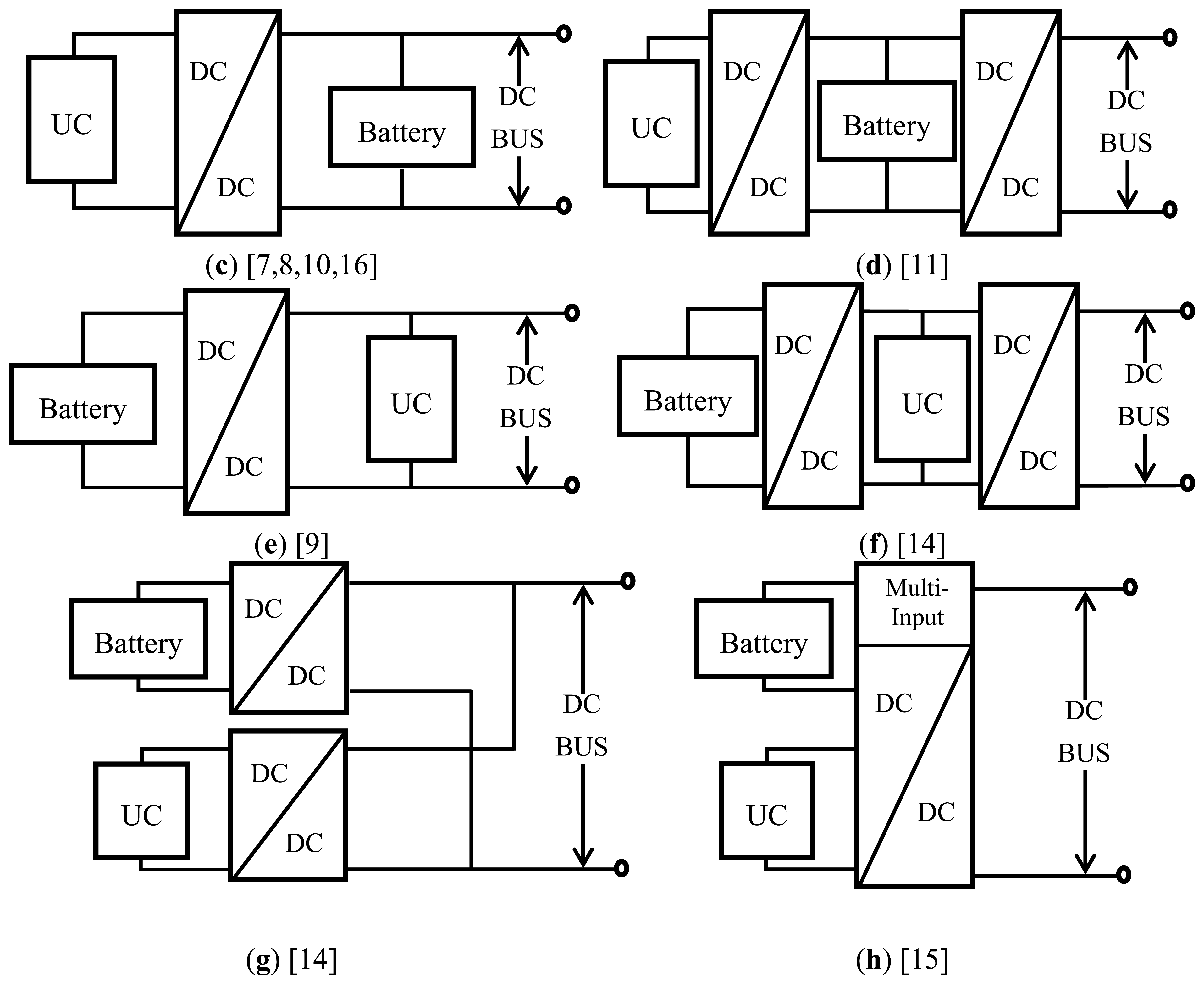
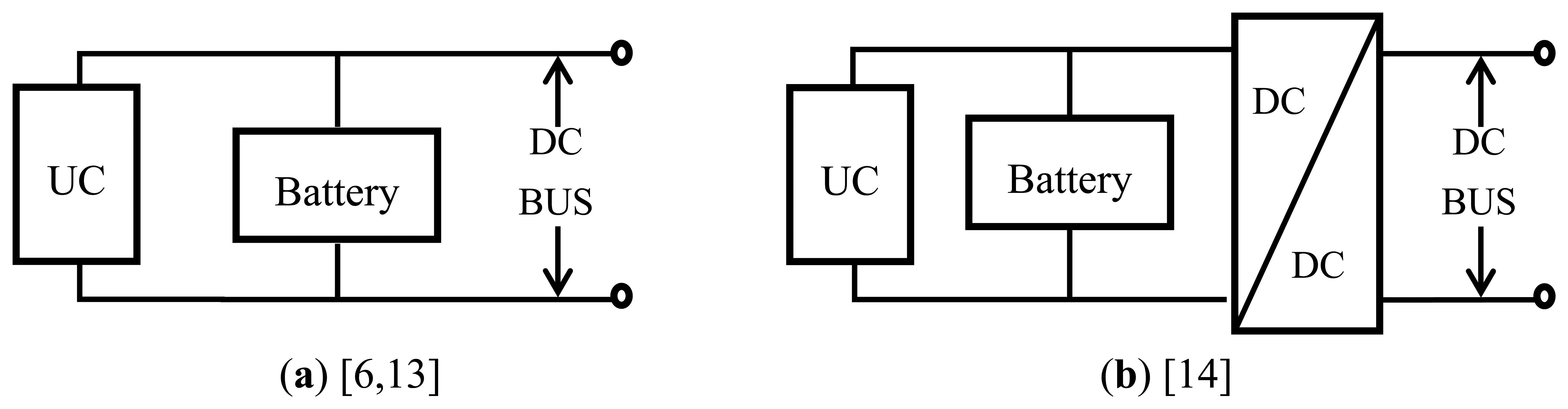
Various architectures for HESSs using batteries and UCs have been proposed [6–16]. The main battery/UC HESS topologies are shown in Figure 1. In the simplest topology, shown in Figure 1a, the UC bank and battery bank are connected in parallel with, and directly to, the DC bus [6]. The conclusions of [13] indicate that the big current of the battery bank in the passive HESSs which are shown in Figure 1a,b is avoided because of the UC bank. In the Figure 1a,b, the power distribution between the batteries and the UCs cannot be controlled.
In recent years, the active parallel HESS topologies shown in Figure 1c–h have been investigated. The power distribution between the batteries and the UCs can be controlled by the DC-DC converter(s). In Figure 1c,d, there is a bi-directional DC-DC converter between the UC bank and the battery bank. In these two topologies, the voltage of the UC bank is not bound by that of the battery bank and the DC bus. In Figure 1c, the battery bank is directly connected to the DC bus in parallel, so the voltage of the DC bus is relatively more stable than that in Figure 1e. In addition, the energy stored in the battery bank can be used more efficiently if it does not have to pass through a DC-DC converter.
In Figure 1e,f, the positions of the battery bank and UC bank are exchanged. In Figure 1e, the UC bank can be used more efficiently, but the voltage of the DC bus varies with the voltage of the UC bank over a large range. Usually, the minimum voltage of the UC bank is half of the maximum.
In Figure 1b,d,f, one bi-directional DC-DC converter is included to stabilize the voltage of the DC bus and separate the energy storage components from the DC bus. However, the overall loss in the system is greater because all the electric energy has to flow through one additional DC-DC converter. Furthermore, the cost, volume and weight of the power electronic devices, especially the high-power components, are not appropriate for the commercial market at present.
In Figure 1g, both the battery bank and the UC bank are connected to the DC bus through a bi-directional DC-DC converter. The more recently developed multi-input bi-directional DC-DC converter can also be used in the HESS, as shown in Figure 1h. In these two topologies, the power distribution between the battery bank and the UC bank can be controlled and the DC bus voltage can be stabilized, but the control strategies are much more complicated and the costs of the DC-DC converter devices are not suitable for the commercial market.
Currently, the topology shown in Figure 1c is the one most widely used. One of the disadvantages of this design is that the DC-DC converter must tolerate high power levels in the system when power is being supplied or absorbed by the UC bank. The necessity of a high-power DC-DC converter hampers the widespread use of an active HESS. Reducing the required power capacity of the bi-directional DC-DC converter in the active parallel structure is an imperative in further research.
In [17], a HESS structure that reduces the required power capacity of the DC-DC converter was proposed, and the three operating modes of this design were discussed. In this design, the snubber capacitor of the motor drive inverter must be removed because there is a step change in voltage when the operating mode switches. Another HESS topology that reduces the required power capacity of the DC-DC converter was proposed in [18], but in that design, if the power capacity requirement of the bi-directional DC-DC converter is reduced, the maximum power requirement of the battery bank must be increased to meet the power demand of the DC bus. Moreover, the battery bank cannot be charged without a DC-DC converter.
To solve the aforementioned problems, a new HESS configuration and control strategy are proposed. The required power capacity of the bi-directional DC-DC converter in the proposed HESS is lower than that in the traditional structure in Figure 1c, and the power requirements of the DC bus are fully satisfied. With the proposed control strategy, there is no step voltage change when the operating mode switches. The controller chooses the appropriate operating mode and distributes the power between the battery bank and the UC bank based on the operating status of the HESS at the previous time step. This approach reduces the power loss and the heat generated by the entire system because both the battery bank and the UC bank can be charged and discharged without using the bi-directional DC-DC converter.
To verify the new HESS configuration and control strategy, simulations and experiments were performed. The development and testing of the HESS and the control strategy are described in the following sections. Section 2 presents the new HESS structure and discusses its four operating modes, and Section 3 introduces the control strategy for the new HESS configuration. Section 4 discusses the simulations, which were developed using the Matlab/Simulink environment, and Section 5 describes the experimental setup and the test results. Finally, conclusions are given in Section 6.
2. Proposed HESS
2.1. Configuration of the Proposed HESS
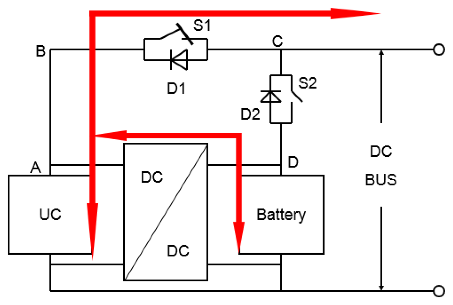
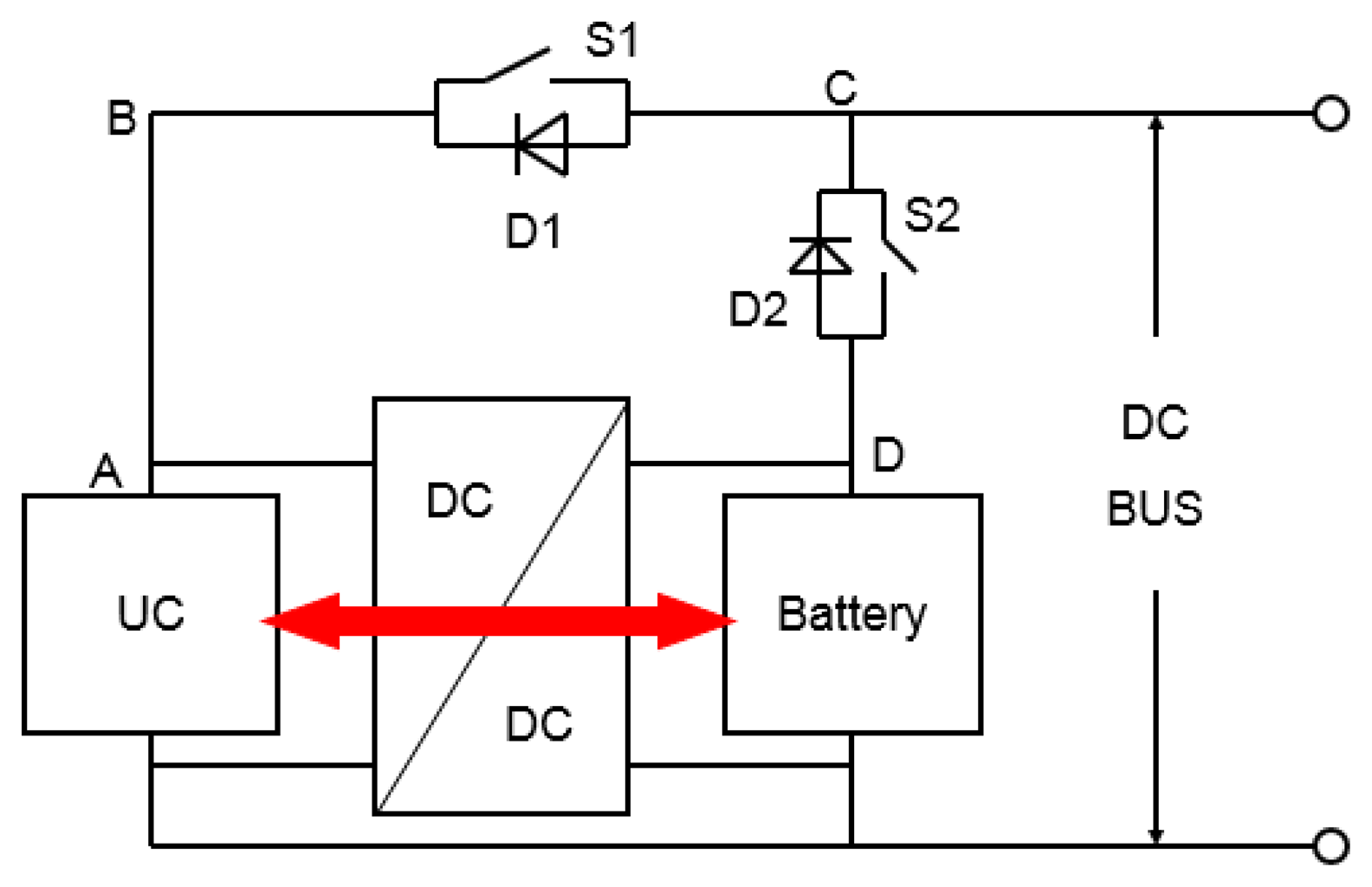
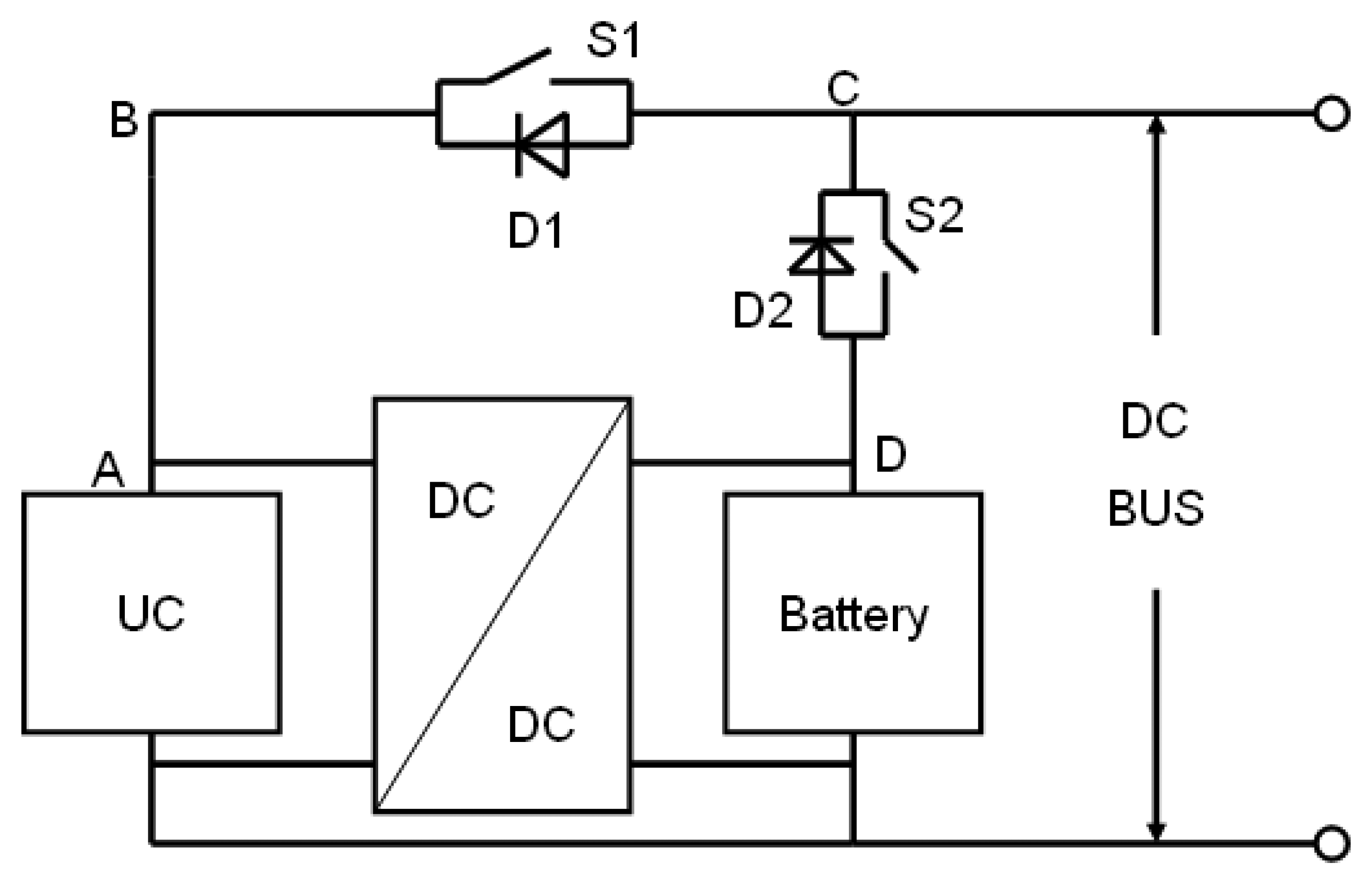
The configuration of the proposed HESS is shown in Figure 2. In this structure, both the UC bank and the battery bank are connected to the DC bus via a switch with a diode in parallel. A bi-directional DC-DC converter is placed between the UC bank and the battery bank. Because of the two diodes, D1 and D2, the voltage of the UC bank is greater than or equal to the voltage of the battery bank, so the high-voltage side of the DC-DC converter is connected to the UC bank and the low-voltage side is connected to the battery bank. The two switches, S1 and S2, can be replaced by relays, MOSFETs, IGBTs or any other power electronic devices according to the actual situation.
2.2. Power Levels of the DC Bus
Given the power limits of the components, the electric power level of the DC bus can be divided into three levels, low, medium, and high. The power level is low if the power level of the DC bus is within the power limit of the battery bank. The power level is medium when the power level of DC bus is greater than the maximum power limit of the battery bank but lower than the sum of the power limits of the battery bank and the DC-DC converter. The power level is high if the power level of DC bus is greater than the sum of the power limits of the battery bank and the DC-DC converter. For the three power levels of the DC bus, the new HESS uses different operating modes.
2.3. Operating Modes
Different states of S1 and S2 in the proposed HESS configuration constitute different operating modes which were designed for the three power levels. Each operating mode is designed for a specific power level, but each mode can be used at lower power levels. For example, Mode I is designed for the high power level, but it can accommodate medium and low power levels. Table 1 lists the states of S1 and S2 and the specific power level of each operating mode. The operating modes are described in detail in this section.
2.3.1. Mode I
Mode I is designed for the high power level. In this mode, as shown in Figure 3, switch S1 is closed and switch S2 is open. All the electric power flowing between the energy storage components and the DC bus flows through S1. If the state of charge (SOC) of the battery bank and voltage of the UC bank are in the appropriate ranges, all the electric energy will be supplied or absorbed by the UC bank. If not, part of the electricity can flow between the battery bank and the DC bus through the DC-DC converter. In this mode, the UC bank is used as the main power source or sink, and the battery bank is used as a supplemental source or sink. The power in the battery bank can be controlled within limits by the DC-DC converter.
2.3.2. Mode II
Mode II is designed for the medium power level. In this mode, switch S1 is open, and switch S2 is closed. All the electricity flowing between the HESS and the DC bus flows through S2. The battery bank supplies or absorbs power within its limits, and any additional power is supplied or absorbed by the UC bank via the DC-DC converter. The energy flows for the medium power level are shown in Figure 4.
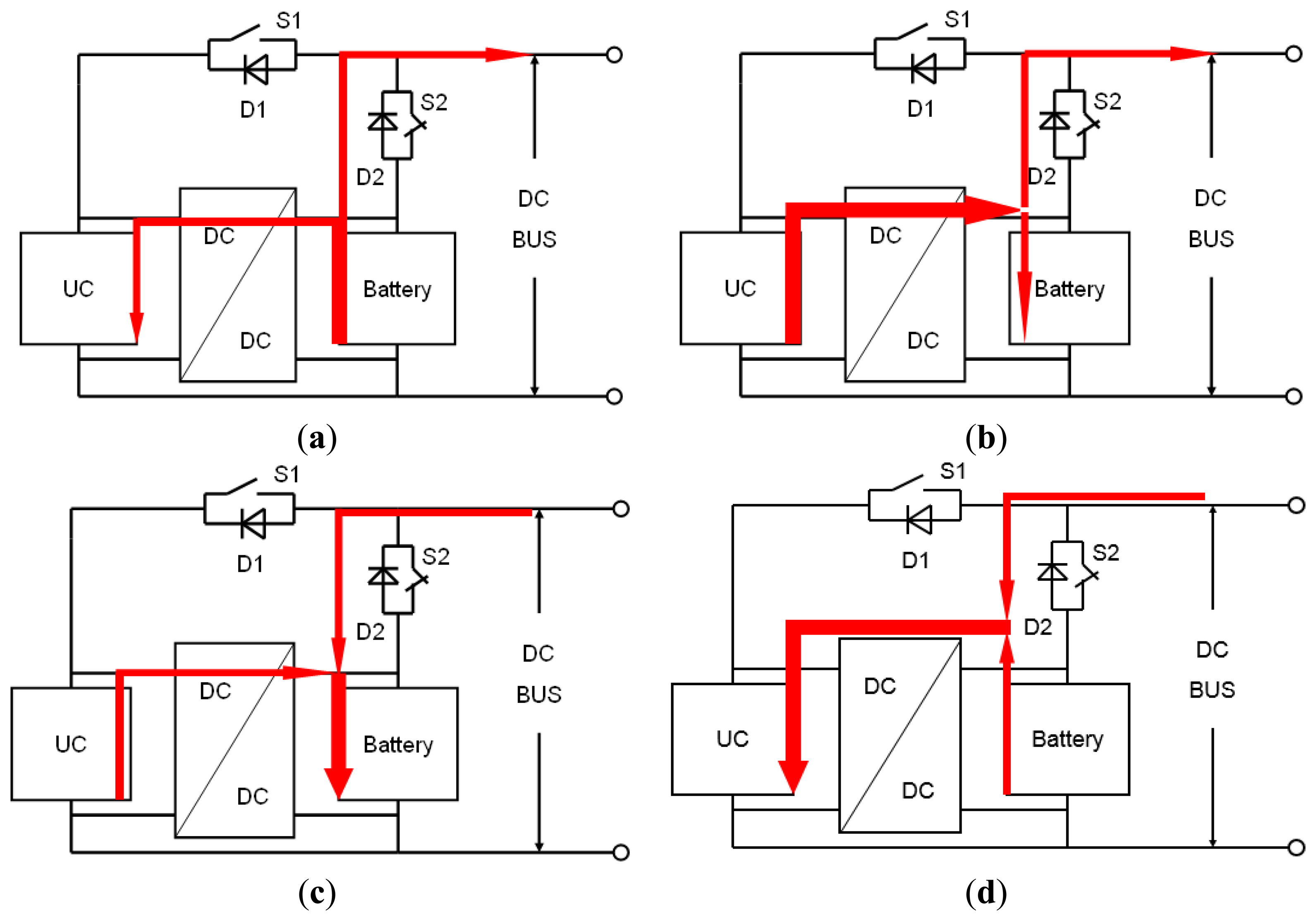
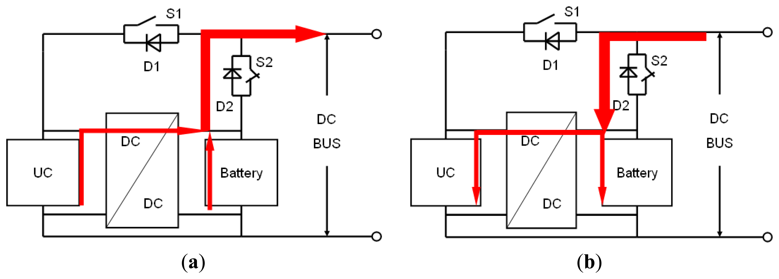
If the SOC of the battery bank or the voltage of the UC bank has to be adjusted when the power level is low, Mode II is used. The possible electric energy flows are illustrated in Figure 5.
When the electricity flows from the HESS to the DC bus, if the SOC of the battery bank is relatively high or the voltage of the UC bank must be increased, the power is allocated as shown in Figure 5a; if the voltage of the UC bank must be decreased or the SOC of the battery bank must be increased, the power is distributed as shown in Figure 5b. When the HESS is required to absorb electric power and the UC bank voltage must be reduced or the SOC of the battery bank must be increased, the power distribution is as shown in Figure 5c; if the battery bank SOC must be reduced or the voltage of the UC bank must be increased, the power is distributed as shown in Figure 5d.
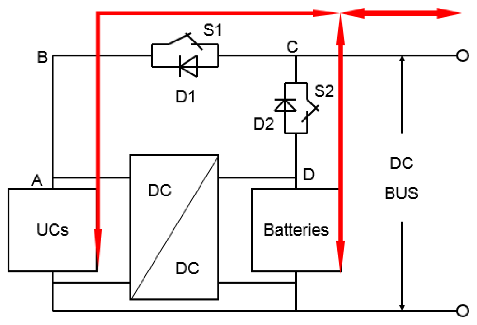
2.3.3. Mode III
When the power level of the DC bus is lower than the limit of the battery bank, Mode III can be used. Both S1 and S2 are closed, and both the batteries and the UCs are connected directly to the DC bus, and the system acts as in the configuration shown in Figure 1a. The input or output current of the HESS will be distributed based on the characteristics of the batteries and the UCs as shown in Figure 6. The UC bank behaves as a low-pass filter in this configuration.
2.3.4. Mode IV
As shown in Figure 7, when there is no power required by the DC bus, electric energy will be transferred between the batteries and the UCs through the DC-DC converter to bring the SOC of the battery bank and the voltage of the UC bank into the desired ranges. This mode can be considered a special case of Mode I or Mode II.
3. Control Strategy for the Proposed HESS Topology
To a great extent, the performance of the HESS is related to the control strategy. For the proposed HESS, mode switching is implemented by controlling S1 and S2. The main consideration in mode switching is closing the switches without a step change in voltage, which may damage the electric devices. Therefore, the switches can be closed only when the voltages across UC bank and the battery bank are the same. This is the main control principle in mode switching.
In addition to mode switching, another important function of the control strategy is to distribute the power between the battery bank and the UC bank. The goal of the control strategy is to regulate the power of the battery bank within the specified limits while accommodating the DC bus power level.
The control strategy is determined based on the mode at the previous time step. As mentioned previously, Mode IV is a special case of Mode I or Mode II, so it will not be discussed separately.
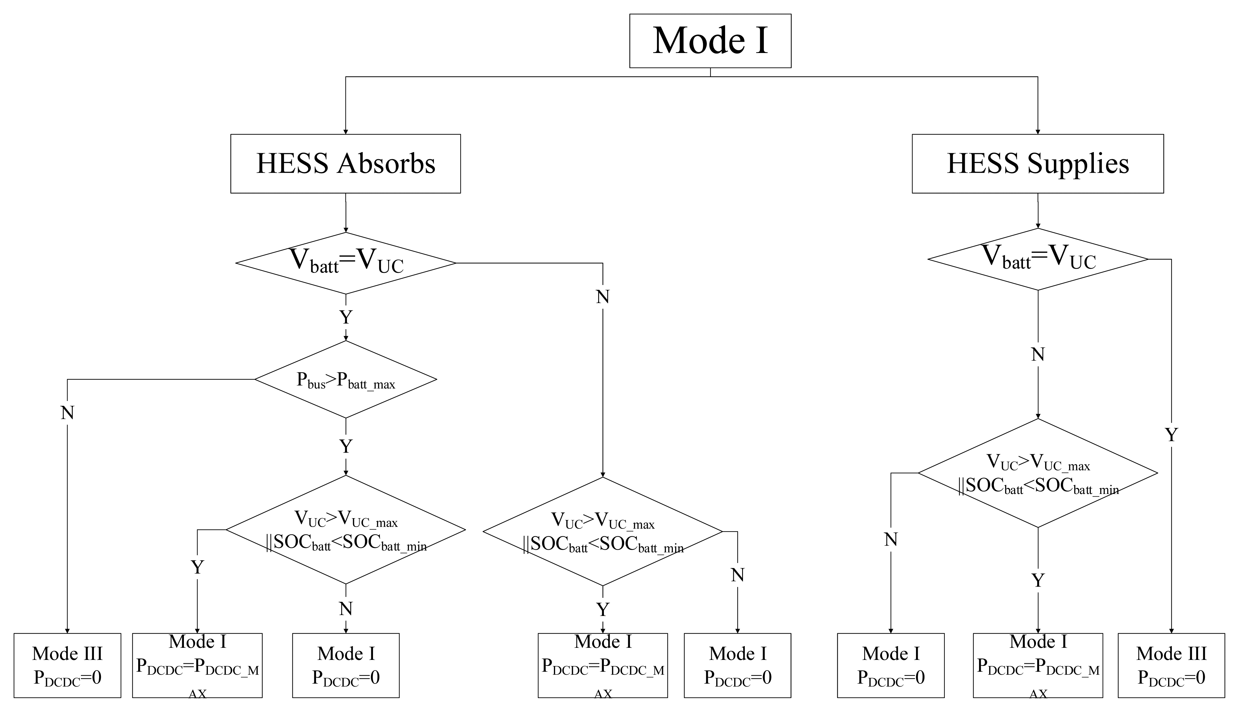
3.1. Mode I
If the mode in the previous step was Mode I, then S1 is closed and S2 is open. The control flowchart is shown in Figure 8. When the HESS is required to absorb electrical energy and the voltages across the battery bank and the UC bank differ, the HESS remains in Mode I. In this mode, the DC-DC converter will be used when the voltage of the UC bank is greater than its upper limit or the SOC of the battery bank is less than its lower limit. If the voltages across the battery bank and the UC bank are equal, the operating mode can be changed when the required power is less than the capacity of the battery bank.
When the HESS is required to supply electrical energy and the voltage of the UC bank is higher than that of the battery bank, the HESS remains in Mode I and the electricity stored in the UC bank will be supplied; if the voltage of the UC bank is equal to the voltage of the battery bank, the operating mode will change from Mode I to Mode III.
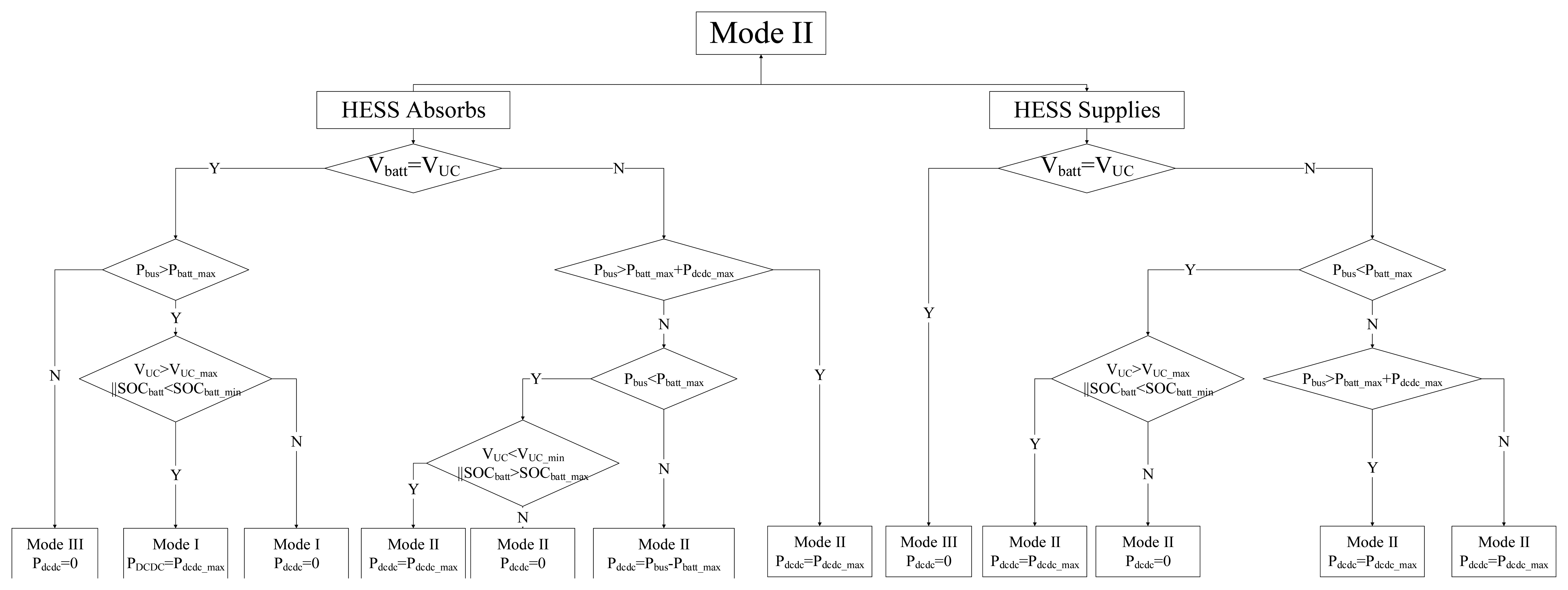
3.2. Mode II
If the mode in the previous step was Mode II, then the battery bank is connected to the DC bus through S2 and the UC bank is connected to the DC bus through the bi-directional DC-DC converter. The control flowchart is shown in Figure 9.
When the HESS is required to absorb electrical energy from the DC bus and the voltages of the battery bank and UC bank are equal, the operating mode of the HESS can be switched. If the recovery power is lower than the power limit of battery bank, the HESS switches to Mode III; if the recovery power is higher than the limit, the HESS switches to Mode I. In Mode I, the DC-DC converter will be used when the voltage of the UC bank is higher than its upper limit or the SOC of the battery bank is less than its lower limit. If the voltage values of the battery bank and the UC bank are not equal, the HESS remains in Mode II and the power from the DC-DC converter changes with the required power of the DC bus. If the HESS is required to supply electricity and the voltages of the battery bank and the UC bank are equal, the HESS changes to Mode III; if not, the HESS remains in Mode II and the power from the DC-DC converter is determined by the required power and the status of the storage components.
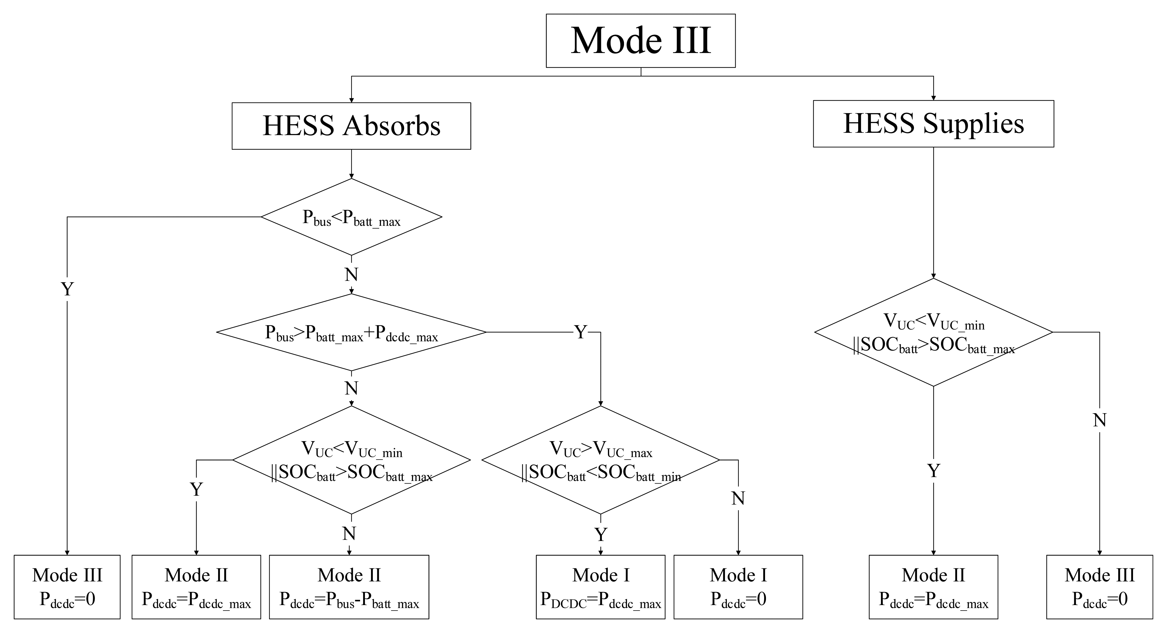
3.3. Mode III
If the HESS is in Mode III, then both the UC bank and battery bank are connected to the DC bus through S1 and S2. The control flowchart is shown in Figure 10. When the HESS is required to absorb electrical energy, the HESS chooses the mode according to the power level of the DC bus, and the power from the DC-DC converter is determined by the current statuses of the UC bank and battery bank.
When the HESS is required to supply electricity and the voltage of the UC is lower than its limit or the SOC of the battery bank is beyond its maximum value, the HESS switches to Mode II and the DC-DC converter operates at maximum power; otherwise, the HESS remains in Mode III.
4. Case Study and Simulation Results
The proposed HESS will be used to improve the performance of an existing power-split, heavy-duty HEV. Based on the design objectives of the HEV, the parameters of the proposed HESS are calculated. To verify the performance of the proposed HESS and control strategy, a model of the HESS was created in the Matlab/Simulink simulation environment.
4.1. Drivetrain Configuration of the HEV
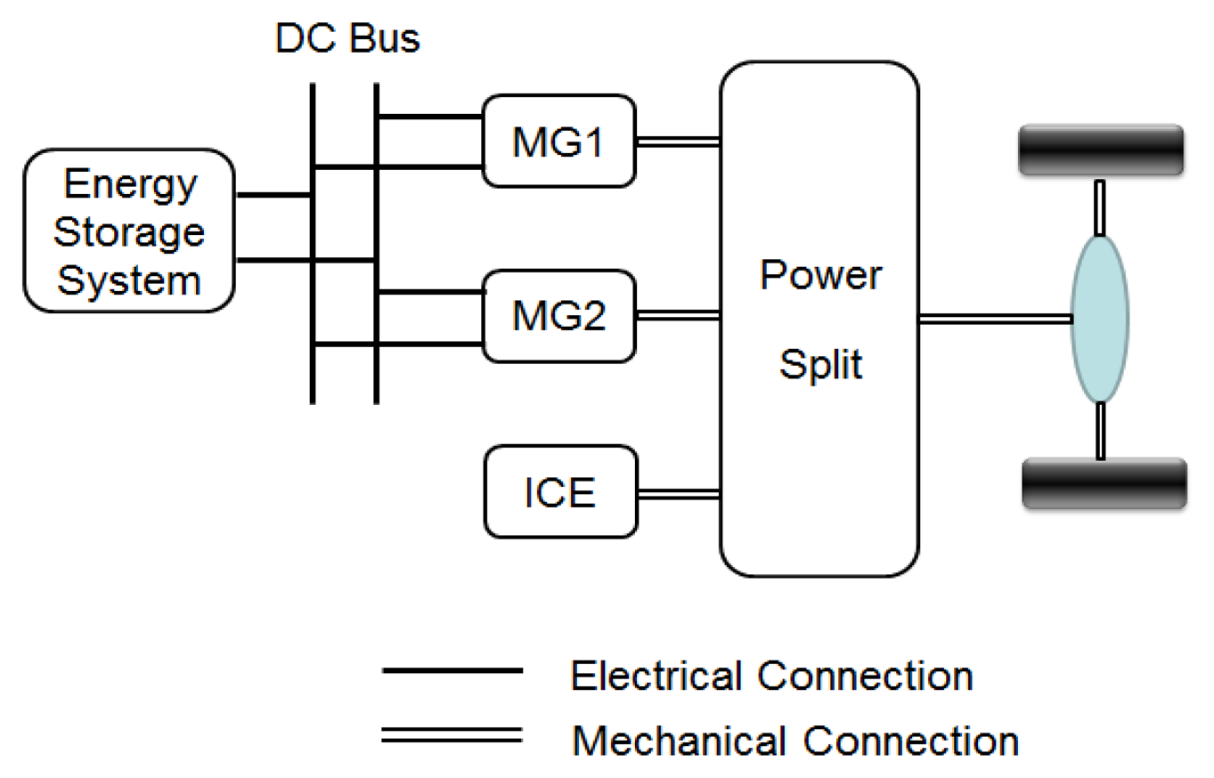
The drivetrain configuration of the power-split HEV is shown in Figure 11 [19]. The drivetrain consists of one internal combustion engine (ICE), two motor/generators (MGs), one battery bank as the ESS and the power-split transmission. The ESS and the two MGs are connected to the DC bus in parallel. The improvement in the performance of the battery bank using the proposed HESS will be demonstrated in the simulations.
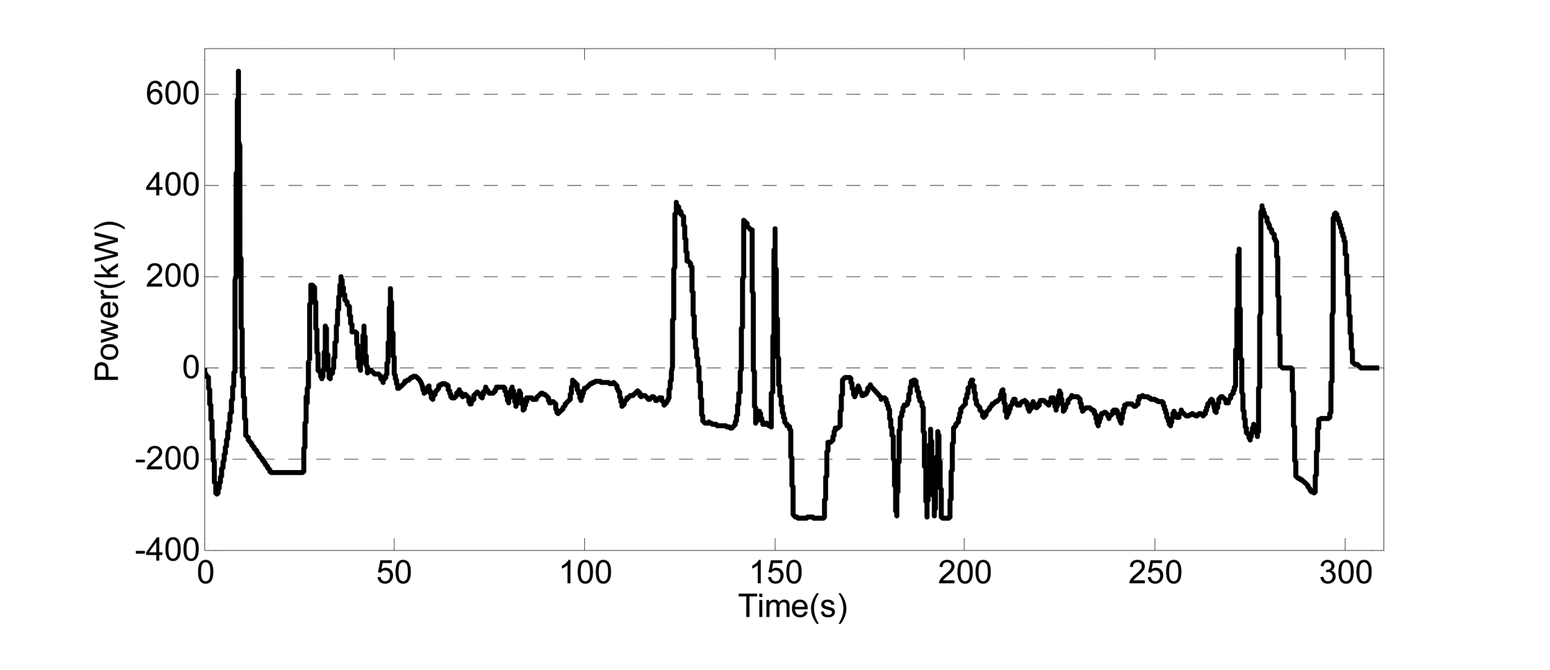
Figure 12 illustrates a part of the experimental data for the DC bus power of the existing HEV. When the DC bus power is positive, the DC bus provides electrical energy to the energy storage system; when the power is negative, the DC bus draws electrical energy from the energy storage system. These experimental data are used for the DC bus power level in the simulation.
4.2. Parameters of the Proposed HESS
4.2.1. Design Objectives for the Proposed HESS
The design objectives of the HEV are used to calculate the parameters of the proposed HESS in this section. When calculating the parameters of the HESS, only the operating conditions in which electrical energy is being transferred must be considered. For this HEV, there are three operating modes in which electrical energy is transferred: the electric drive mode, the acceleration mode and the regenerative mode. In the electric drive mode, it is required that the HEV drive 1 hour at a speed of 15 km/h using electrical energy only. In the regenerative mode, the design goal is to decelerate from 85 km/h to 0 km/h in 5 s. The design target of the acceleration mode is to accelerate from 0 to 32 km/h in 7 s. The power and energy demands of these three operating modes were calculated in [20], and they are listed in Table 2.
The characteristics of the batteries and the UCs are such that the battery bank, with its high energy density, is used to meet the maximum energy and power demands in the electric drive mode, and the UC bank, with its high power density, is used to match the high power levels in the regenerative and acceleration modes.
4.2.2. Battery Bank Parameters
The battery bank of the proposed HESS uses the batteries from the existing drivetrain. The main parameters of the battery cells are shown in Table 3.
The calculation method for the parameters of the battery bank was presented in [20]. The results of these calculations are shown in Table 4.
4.2.3. UC Bank Parameters
The UC bank in the proposed HESS is used to match the power levels in the regenerative mode and the acceleration mode. In addition, the energy capacity of the UC bank must be sufficient to match the bus energy levels of these two modes.
- (1)
The quantity of cells in series in the UC bank
For the configuration of the proposed HESS, the lower voltage limit of the UC bank should be equal to the lower voltage limit of the battery bank. The series number of the UC bank is calculated from Equation (1).
where nuc is the quantity of cells in series in the UC bank, Vuc_min is the minimum voltage of one UC, Vucbank_min is the minimum voltage of the UC bank, and Vbattbank_min is the minimum voltage of the battery bank.The value of Vbattbank_min was set to 420 V. Generally, Vuc_min is set to 1/2 of the upper voltage limit of the UC cells. The upper voltage limit of the chosen UC cells is 2.7 V, so considering the margin, Vuc_min was set to 1.4 V. Then, nuc can be calculated from Equation (1), which gives a value of 300.
- (2)
The capacity of one UC
The UC bank for the proposed HESS should absorb the maximum reclaimed energy for one application of the brakes and the given design objectives. The capacity of one UC can be calculated using Equation (2):
where C is the capacity of one UC, Vuc_max is the upper voltage limit of one UC (2.7 V), Ebrake is the maximum recovered energy of design objectives, t is the braking time (5 s according to the design objectives) and Pdc−dc is the power limit of the bi-directional DC-DC converter.The calculated results for one UC capacity for various power limits on the DC-DC converter are listed in Table 5. These values would be used to select the actual UC products.
4.3. Simulation Model
The proposed HESS model was built in the Matlab/Simulink simulation environment; the Simulink model is shown in Figure 13. The model includes the UC bank, the battery bank, the DC bus, the bi-directional DC-DC converter, the control module, the switches S1 and S2 and the diodes D1 and D2.
The DC bus module varies the electric power produced or consumed by the DC bus according to the experimental data shown in Figure 12. If the bus power is positive, the electrical energy flows from the DC bus to the HESS; if the bus power is negative, the electrical energy flows from the HESS to the DC bus.
The battery bank was modeled in Matlab/Simulink, and all the parameters were set to those for the chosen battery and shown in Table 2. Because the internal resistance of the UC is much smaller than that of the batteries, the UC bank is assumed to be an ideal capacitor. The UC capacity was chosen based on Table 3.
In the simulation model, the main function of the bi-directional dc-dc converter is distributing the power between the UC bank and the battery bank and the loss is neglected. So in simulation, the bi-direction DC-DC converter is built by the controlled current sources to implement the function.
The control block calculates the power from the DC-DC converter and the states of S1 and S2 according to the control strategy presented in Section 3. S1, D1, S2 and D2 are assumed to be ideal components.
4.4. Simulation Results
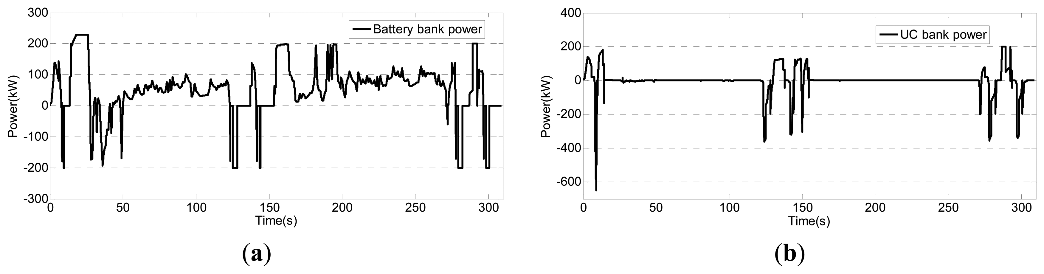
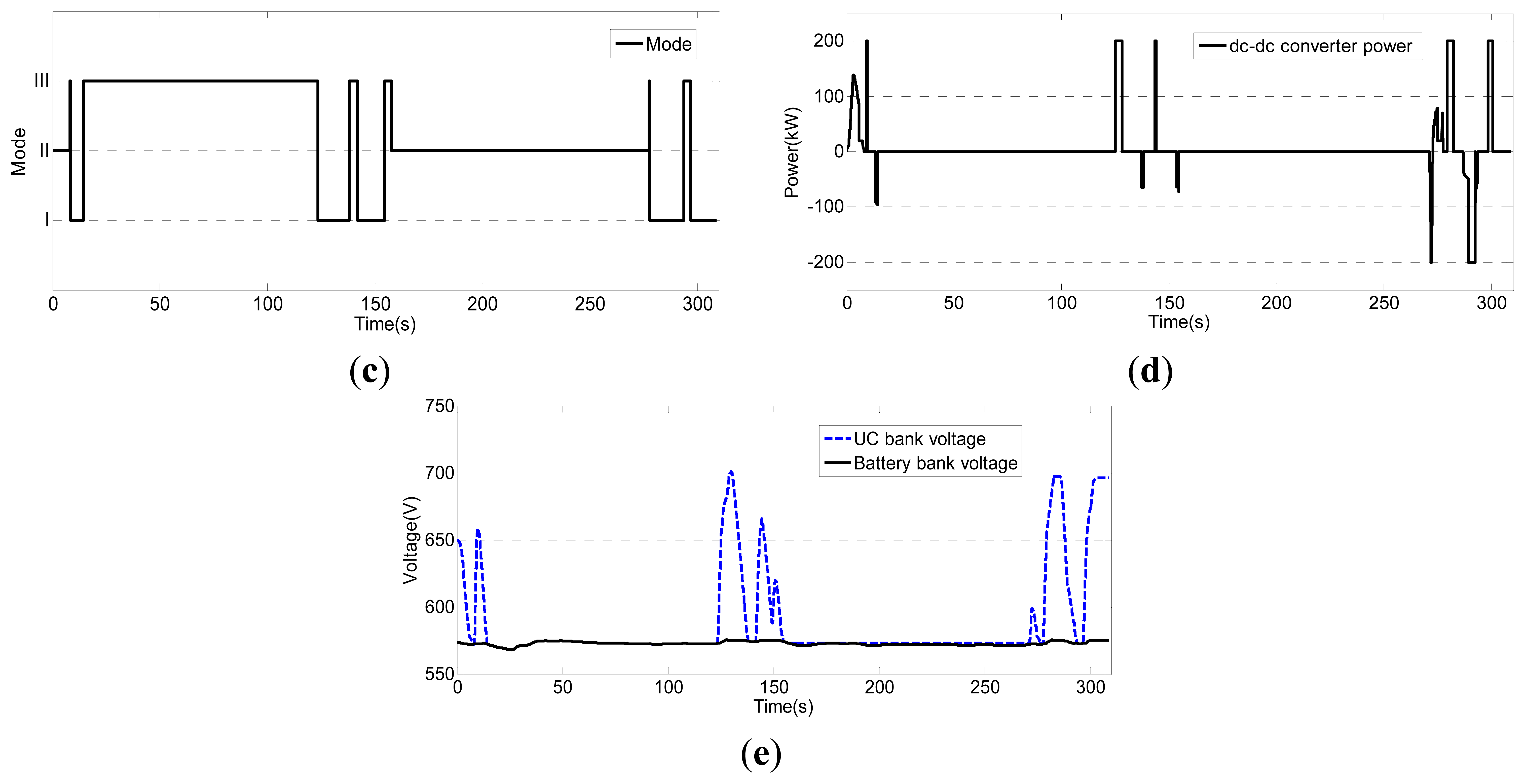
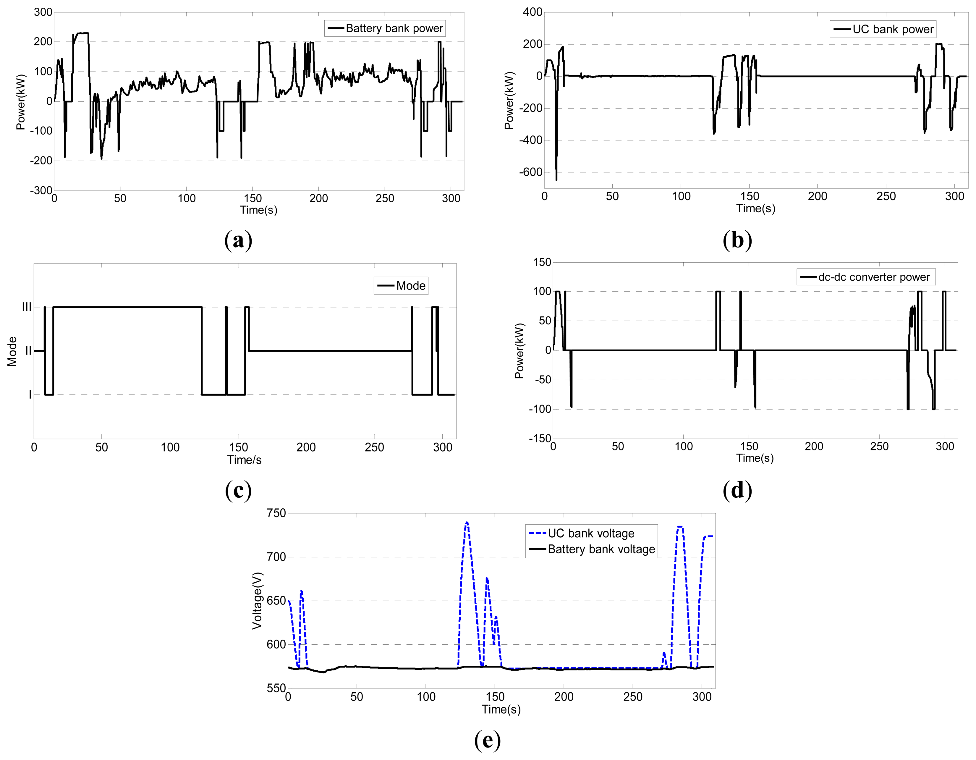
Two sets of simulation results are shown in Figures 14 and 15. In Figure 14, the power limit of the bi-directional DC-DC converter is 200 kW, and in Figure 15, the power limit is 100 kW. In both of the simulations, the power limit of the battery bank is 250 kW. In the conventional configuration shown in Figure 1c, when the power limit of the battery bank is 250 kW, the power capacity of the bi-directional DC-DC converter must be at least 400 kW to accommodate the 650 kW peak (in the regenerative mode) shown in Figure 12.
The proposed HESS and control strategy performed as expected. The proposed HESS with the parameters calculated in Section 4.2 provided sufficient power and energy for the HEV. The power in the battery and the bi-directional DC-DC converter were maintained within their respective limits. The appropriate operating mode was chosen, and no current spikes occurred during mode switching.
As can be observed in the simulation results, when the power limit of the DC-DC converter is lowered, the peak voltage of the UC bank is increased which means more energy stored in the UC bank, but the power levels of the DC bus can be matched without increasing the power capacity of the battery bank.
5. Experiments and Results
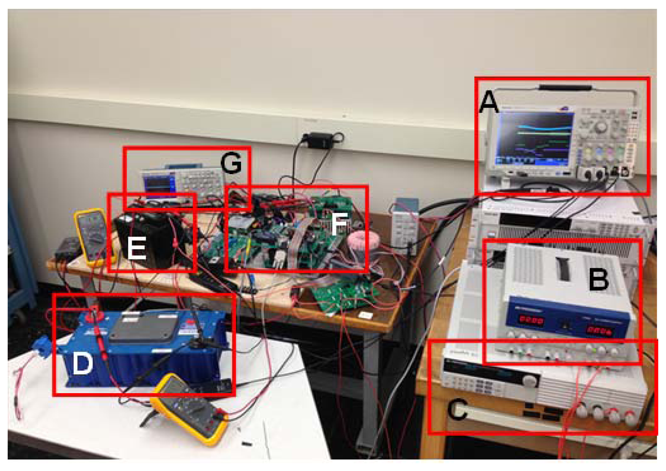
A scaled-down experimental platform was constructed to verify the feasibility of the proposed HESS and control strategy. The platform is shown in Figure 16. The main components of the platform are listed in Table 6. Two MOSFETs with parallel diodes were used for S1, S2, D1 and D2. The bi-directional DC-DC converter was fabricated in-house based on MOSFET. It performed in buck mode when the power flows from UC bank to the battery bank, and it works in boost mode in another direction. The converter is controlled by TMS320F28335. A dual-loop control strategy is built with voltage and current close-loop control and the converter works in continue current mode. Both of current limits of the battery bank and the bi-directional DC-DC converter are set to 2 A. In the experiments, the current to/from the bi-directional DC-DC converter on the battery bank side was measured. The DC power supply and the DC electric load were used to represent the DC bus load seen by the HESS. The DC power supply supplies electrical energy to the HESS, and the DC electric load draws electrical energy from the HESS. In the experimental results, the power provided by the DC power supply is positive and the power drawn by the DC electric load is negative.
Both charging and discharging tests were performed on the test platform. The results are presented in Figures 17, 18 and 19.
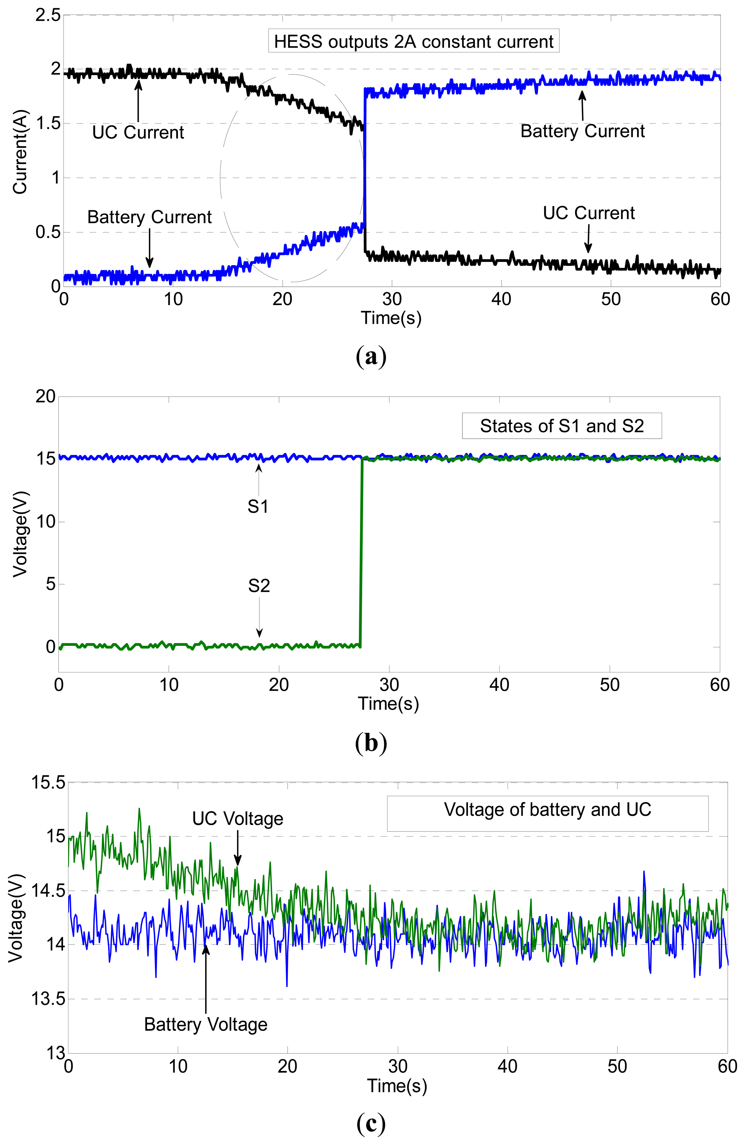
Figures 17 and 18 give the experimental results when the HESS is discharging with constant 2 A current. In Figure 17, the HESS is initially in Mode I, and the initial voltage of the UC bank is 1 V higher than that of the battery bank.
The process of switching from Mode I to Mode III is demonstrated in Figure 17. The DC-DC converter was not involved in this test. At the beginning of this test, all the electrical energy was supplied by the UC bank, and the voltage of the UC bank decreased. When the voltage of the UC bank decreased to nearly the voltage of the battery bank, the internal resistance caused the output current of the UC bank to decrease, and the output current of the battery bank increased, as can be observed in the area circled in Figure 17a. When the voltage of the UC bank was equal to the voltage of the battery bank, switch S2 closed and the HESS began to operate in Mode III. In Mode III, most of the energy flows from the battery bank.
In Figure 18, the HESS is initially in Mode II, and the voltage of the UC bank is 1 V higher than the voltage of the battery bank. In this experiment, the operating mode switches from Mode II to Mode III. Prior to 33.8 s, the HESS operated in Mode II, and the DC-DC converter was engaged. Both the UC bank and the battery bank were supplying electrical energy. When the voltage of the battery bank and UC bank were equal, the HESS switched from Mode II to Mode III. In Mode III, the DC-DC converter was not engaged and the current was distributed based on the internal resistances of the two energy storage banks.
In the next test, a variable positive load current, which is shown in Figure 19a, was applied. The currents in the battery bank, the UC bank and the DC-DC converter are shown in Figure 19b–d, respectively. The initial operating mode in this test was Mode III, and the current limit on the battery bank was 2 A.
When the load current was less than 2 A, the HESS remained in Mode III, and most of the electrical energy flowed into the battery bank. When the load current increased to the limit of the battery bank, the HESS switched to Mode I. Subsequently, all the energy flowed into the UC bank, and the voltage of the UC bank increased. When the voltage difference between the UC bank and the battery bank increased to the threshold, which was set to 0.5 V in this experiment, the DC-DC converter was engaged. The 2 A load current flowed through the DC-DC converter into the battery bank to maintain the voltage within the desired range.
6. Conclusions
In this study, a new HESS configuration and control strategy were investigated. The main purpose of the new structure is to reduce the required power capacity of the bi-directional DC-DC converter in the HESS while matching the power level in the DC bus. The new HESS has four operating modes, which were discussed in detail. Based on the DC bus power level, the operating mode at the previous step and the voltages of battery bank and the UC bank, the control strategy chooses the operating mode for the next step and calculates the necessary power in the DC-DC converter.
The performance of an existing HEV was improved using the proposed HESS. Simulations of the proposed configuration and control strategy were performed in the Matlab/Simulink simulation environment. A method for calculating the parameters of the proposed HESS was presented. The simulation results showed that with the calculated values of the parameters, the proposed HESS could satisfy the power and energy demands of DC bus with a lower-capacity DC-DC converter than was required with the traditional HESS topology. The power in the battery bank and the DC-DC converter were maintained within the specified limits. The results for two power limit values show that the performance of the system is not affected by the power limit of the DC-DC converter.
A scaled-down experimental platform was constructed to verify the performance of the proposed HESS. The test results showed that the configuration is viable. The HESS switched between operating modes as required. The control strategy is feasible for the proposed HESS topology.
Acknowledgments
We would like to express our deep gratitude to Chris Mi in the University of Michigan Dearborn. This work was supported by the National Natural Science Foundation of China (51005017) and the Fundamental Research Funds for the Central Universities (2014QNA4012).
Conflicts of Interest
The authors declare no conflict of interest.
References
- Sheldon, S.W. Electric and Plug-in Hybrid Electric Vehicle Drive Train Topologies. In Energy Management Strategies for Electric and Plug-in Hybrid Electric Vehicle; Springer, New York: New York, NY, USA, 2013; pp. 7–14. [Google Scholar]
- Siang, F.T.; Chee, W.T. A Review of Energy Sources and Energy Management System in Electric Vehicles. Renew. Sustain. Energy Rev. 2013, 20, 82–102. [Google Scholar]
- Alireza, K.; Li, Z.H. Battery, Ultracapacitor, Fuel Cell, and Hybrid Energy Storage Systems for Electric, Hybrid Electric, Fuel Cell, and Plug-In Hybrid Electric Vehicles: State of the Art. IEEE Trans. Veh. Technol. 2010, 59, 2806–2814. [Google Scholar]
- Miller, J.M.; Bohn, T.; Dougherty, T.J. Why Hybridization of Energy Storage is Essential for Future Hybrid, Plug-in and Battery Electric Vehicles. Proceedings of the Energy Conversion Congress and Exposition, San Jose, CA, USA, 20–24 September 2009.
- Andrew, B. Ultracapacitors: Why, how, and where is the technology. J. Power Sources 2000, 91, 37–50. [Google Scholar]
- Pay, S.; Baghzouz, Y. Effectiveness of Battery-Supercapaicitor Combination in Electric Vehicles. Proceedings of the IEEE Power Tech Conference, Bologna, Italy, 23–26 June 2003.
- Pan, C.; Chen, L.; Chen, L. Research on Energy Management of Dual Energy Storage System Based on the Simulation of Urban Driving Schedules. Int. J. Electr. Power Energy Syst. 2013, 44, 37–42. [Google Scholar]
- Miller, J.M.; Sartorelli, G. Battery and Ultracapacitor Combinations-Where should the converter go? Proceedings of the Vehicle Power and Propulsion Conference, Lille, France, 1–3 September 2010.
- Liu, X.; Zhang, Q.; Zhu, C. Design of Battery and Ultracapacitor Multiple Energy Storage in Hybird Electric Vehicle. Proceedings of the Vehicle Power and Proposion Conference, Dearborn, MI, USA, 7–10 September 2009.
- Niemoeller, B.A.; Krein, P.T. Battery-ultracapacitor Active Parallel Interface with Indirect Control of Battery Current. Proceedings of the Power and Energy Conference, Urbana-Champaign, IL, USA, 12–13 February 2010.
- Miller, J.M.; McCleer, P.J.; Everett, M. Ultracapacitor Plus Battery Energy Storage System Sizing Methodology for HEV Power Split Electric CVT's. Proceedings of the 2005 IEEE International Symposium on Industrial Electronics, Dubrovnik, Croatia, 20–23 June 2005.
- Bobba, P.B.; Rajagpal, K.R. Modeling and Analysis of Hybrid Energy Storage Systems Used in Electric Vehicles. Proceedings of the 2012 IEEE International Conference on Power Electronics, Drives and Energy Systems, Bengaluru, India, 16–19 December 2012.
- He, H.W.; Xiong, R.; Chang, Y.H. Dynamic Modeling and Simulation on a Hybrid Power System for Electric Vehicle Applications. Energies 2010, 3, 1821–1830. [Google Scholar]
- Lukic, S.M.; Wirasingha, S.G.; Rodrigue, F. Power Management of an Ultracapacitor/Battery Hybrid Energy Storage System in an HEV. Proceedings of the Vehicle Power and Propulsion Conference, Windsor, UK, 6–8 September 2006.
- De Castro, R.; Pnto, C.; Araujo, R.E. Optimal Sizing and Energy Management of Hybrid Storage System. Proceedings of the Vehicle Power and Propulsion Conference, Seoul, Korea, 9–12 October 2012.
- Ortuzar, M.; Moreno, J.; Dixon, J. Ultracapacitor-based Auxiliary Energy System for an Electric Vehicle: Implementation and Evaluation. IEEE Trans. Ind. Electron. 2007, 54, 2147–2156. [Google Scholar]
- Lu, S.; Corzine, K.A.; Ferdowsi, M. A New Battery/Ultracapacitor Energy Storage System Design and Its motor Drive Integration for Hybrid Electric Vehicles. IEEE Trans. Veh. Technol. 2007, 56, 1516–1523. [Google Scholar]
- Cao, J.; Emadi, A. A new Battery/Ultracapacitor Hybrid Energy Storage System for Electric, Hybrid, and Plug-in Hybrid Electric Vehicles. IEEE Trans. Power Electron. 2012, 27, 122–132. [Google Scholar]
- Zhang, D.; Xiang, C.; Han, L. Design and Performance Prediction of aTri-Mode Power-Split Transmission. Proceedings of the FISITA 2012 World Automotive Congress Lecture Notes in Electrical Engineering, Beijing, China, 27–30 November 2012.
- Xiang, C.; Wang, Y.; Wang, W. Research on Parameter Matching and Fuzzy Logic Control Strategies of EMT Hybrid Energy Storage System. Proceedings of the FISITA 2012 World Automotive Congress Lecture Notes in Electrical Engineering, Beijing, China, 27–30 November 2012.


| Mode | S1 | S2 | Power level |
|---|---|---|---|
| I | 1 | 0 | High |
| II | 0 | 1 | Medium |
| III | 1 | 1 | Low |
| Power (kW) | Energy (kW·h) | |
|---|---|---|
| Electric drive mode | 88.5 | 88.5 |
| Regenerative mode | 829 | 0.8763 |
| Acceleration mode | 372 | 0.1756 |
| Rated Capacity | 35 Ah | Rated Voltage | 3.7 V |
| Mass Energy Density | ≥135 Wh/kg | Volume Energy Density | ≥225 Wh/L |
| Cycling Performance | ≥2500 | Self-Discharge | ≤5% |
| Temperature Range | −20∼55 °C | Mass | 1080 ± 10 g |
| Quantity in Series | 245 |
| Quantity in Parallel | 9 |
| DC-DC power limit (kW) | 50 | 100 | 150 | 200 | 250 |
| UC cell capacity (F) | 3632 | 3320 | 3007 | 2694 | 2382 |
| Key | Item | Manufacturer/Model Number |
|---|---|---|
| A | Oscilloscope | MDO4054-3 |
| B | DC Power Supply | BK PRECISION 1760A |
| C | DC Electric Load | BK PRECISION 8514 |
| D | UC Bank | BMOD0110 P48 110 F, 48 V |
| E | Battery Bank | Valence U1-12XP 12.8 V, 40 Ah |
| F | Bi-directional DC/DC Converter | N/A |
| S1, D1 and S2, D2 | IPW60R041C6 | |
| Control unit | TMS320F28335 | |
| G | Oscilloscope | TDS 2024C |
© 2014 by the authors; licensee MDPI, Basel, Switzerland. This article is an open access article distributed under the terms and conditions of the Creative Commons Attribution license( http://creativecommons.org/licenses/by/3.0/).
Share and Cite
Xiang, C.; Wang, Y.; Hu, S.; Wang, W. A New Topology and Control Strategy for a Hybrid Battery-Ultracapacitor Energy Storage System. Energies 2014, 7, 2874-2896. https://doi.org/10.3390/en7052874
Xiang C, Wang Y, Hu S, Wang W. A New Topology and Control Strategy for a Hybrid Battery-Ultracapacitor Energy Storage System. Energies. 2014; 7(5):2874-2896. https://doi.org/10.3390/en7052874
Chicago/Turabian StyleXiang, Changle, Yanzi Wang, Sideng Hu, and Weida Wang. 2014. "A New Topology and Control Strategy for a Hybrid Battery-Ultracapacitor Energy Storage System" Energies 7, no. 5: 2874-2896. https://doi.org/10.3390/en7052874