Dynamic Response of a 50 kW Organic Rankine Cycle System in Association with Evaporators


Abstract
: The influences of various evaporators on the system responses of a 50 kW ORC system using R-245fa are investigated in this study. First the effect of the supplied hot water flowrate into the evaporator is examined and the exit superheat on the system performance between plate and shell-and-tube evaporator is also reported. Test results show that the effect of hot water flowrate on the evaporator imposes a negligible effect on the transient response of the ORC system. These results prevail even for a 3.5-fold increase of the hot water flowrate and the system shows barely any change subject to this drastic hot water flowrate change. The effect of exit superheat on the ORC system depends on the type of the evaporator. For the plate evaporator, an exit superheat less than 10 °C may cause ORC system instability due to considerable liquid entrainment. To maintain a stable operation, the corresponding Jakob number of the plate heat evaporator must be above 0.07. On the other hand, by employing a shell and tube heat evaporator connected to the ORC system, no unstable oscillation of the ORC system is observed for exit superheats ranging from 0 to 17 °C.1. Introduction
The Organic Rankine Cycle (ORC) is similar to a conventional Rankine cycle except it uses organic fluids as a working fluid rather than water. Since the specific vaporization heats of organic fluids are generally much lower than that of water [1], the ORC is especially viable for low grade heat recovery. It had been statistically estimated that the low-grade waste heat accounts for more than 50% of the total amount of heat generated in industry [2], therefore exploitation of the ORC for harvesting low grade energy has become quite promising for the past few decades. This is because the ORC can efficiently produce shaft-work from medium temperature heat sources up to 370 °C [2]. In contrast to the conventional power cycles, the ORC fluids fits perfectly in local and small scale power generation applications [3]. The working fluids applicable for ORC system depend on the temperature of waste heat. A more detailed review of methods of screening the working fluids can be found Hung et al. [2], Saleh et al. [3], Liu et al. [4], and Chen et al. [5].
A wide variety of ORC systems have been implemented. A recent review by Vélez et al. [6] pointed out the diversity of ORC applications, including waste heat recovery, solar energy utilization, biomass application, water desalination, geothermal systems, or engine exhaust gases, and the like. However, despite all these versatile applications of ORC systems, detailed elaborations about the experimental results concerning the system response are comparatively scarce. For examples, Kang [1] designed a radial turbine which was directly connected to the high-speed synchronous generator and R-245fa was adopted as the working fluid. Experiments were conducted to analyze the operational characteristics and performance of the developed ORC. Wang et al. [7,8] conducted an experimental study to investigate the performance of a low-temperature solar Rankine cycle system using R-245fa. Their measured cycle efficiency was lower than the theoretical value. They attributed the deficiency to superheating/subcooling of the working fluid and the heat loss of the experimental system. Manolakos et al. [9] performed an on-site experimental evaluation of the performance of a low-temperature solar organic Rankine cycle system (SORC) for reverse osmosis (RO) desalination. A special energy recovery by axial pistons pumps had been integrated with the RO unit to minimize the energy consumption. They showed that the concept is feasible and a continuous operation is achieved under intermittent solar energy availability conditions. Quoilin et al. [10] presented a numerical model for an ORC system and its experimental validation with the refrigerant HCFC-123. The heat sources were from two hot air flows. Their measured performance of the ORC system agreed with their numerical model. Borsukiewicz-Gozdur [11] conducted an experimental investigation of an ORC power plant which uses R-227ea as the working fluid. The electric efficiency of the ORC power plant during all the test runs was around 4.88%.
The abovementioned studies were mainly operated under steady or quasi-steady conditions. For the dynamic response of an ORC system, Lee et al. [12] investigated the dynamic behaviors of a 50 kW ORC system subject to the operating conditions of the condenser. They found that with a sharp rise of the water coolant flow rate in the condenser, the output power is first slightly increased, followed by a sharp decline to barely any output power and it remains there until the end of the transient. The output power increased back right after the transient and exceeded its original state. There is almost no R-245fa mass flow rate during the power outage period, yet the evaporation pressure also experienced a gigantic falloff during the transient period. This peculiar surge phenomenon is related to the tremendous change of the total void in the condenser, leading to a momentary reduction of the R-245fa mass flow rate. From the foregoing discussion of previous efforts, it appears that the dynamic characteristics of the heat exchangers have a significant impact on ORC systems. Hence, it is the purpose of the present study to extend further examinations of the influences on the system performance subject to various types of evaporators. In this study, influence of the supplied flowrate variation in the evaporator on a 50 kW ORC is first examined. In practice, both a plate heat exchanger and a shell-and-tube heat exchanger can be used as the evaporators, and these different evaporators may give rise to different system responses, which will be also reported in this study.
2. System Construction and Measurements
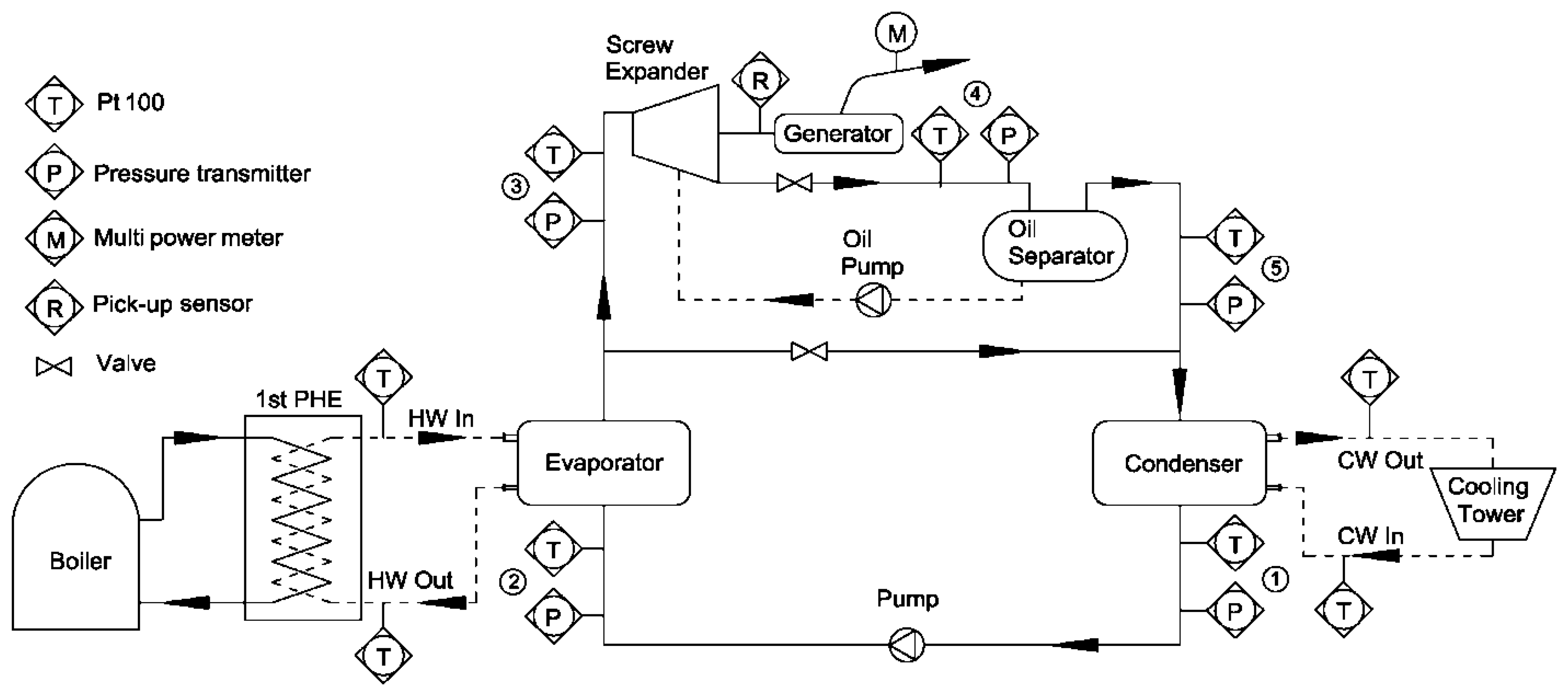
The schematic diagram of the 50 kW ORC system is shown in Figure 1. The major components of the ORC include a multi-stage liquid pump, an evaporator, a shell-and-tube condenser with four-pass design, a screw expander and a generator, and an oil separator.
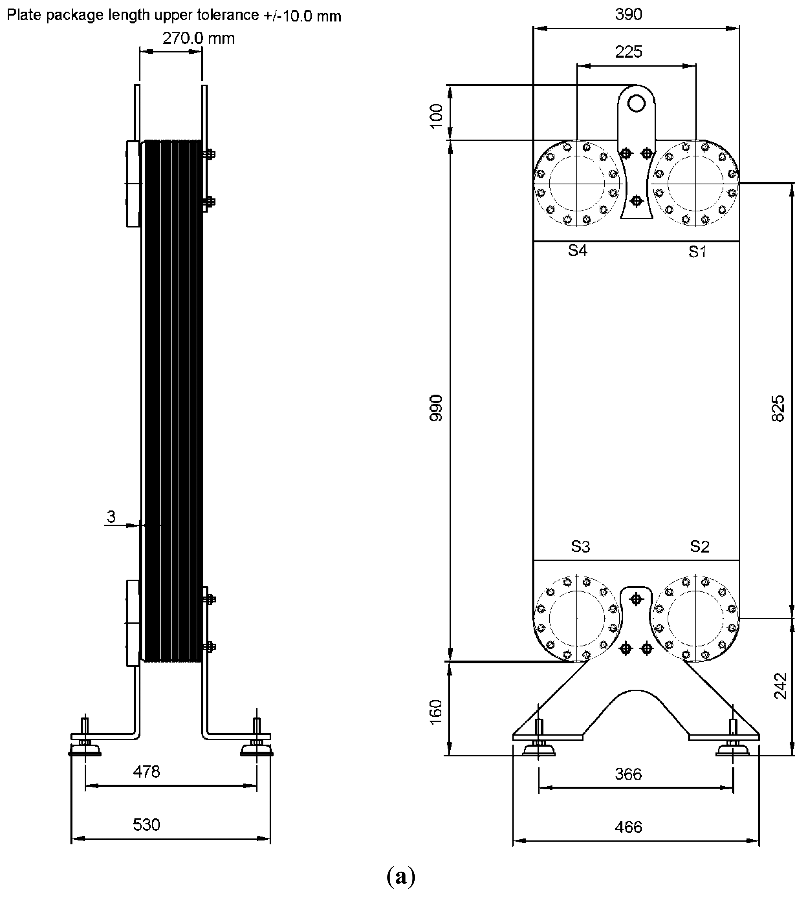
The working fluid is R-245fa for its comparatively high thermal efficiency, as screened by Saleh et al. [3]. The 7.5 kW pump is a multistage centrifugal pump having 12 impellers with a nominal rating flow rate of 2.1 m3/h equipped with a maximum discharge pressure of 2500 kPa. The power input to the R-245fa is from an external power source. The screw expander is a semi-hermetic twin screw (model RC2-410AF, made by Hanbell Precise Machinery Co. Tao-Yuan, Taiwan). The electrical generator is coupled with the expander and is enclosed in the same housing. The corresponding expansion ratio is 4.8 having a nominal volumetric flow rate of 480 m3/h. In this study, both plate heat exchanger and shell-and-tube heat exchangers are used as the evaporator for further comparison. The counter-currently arranged plate evaporator is fully welded type (Alfa Laval, Lund, Sweden) with a total of 100 plates as shown in Figure 2a. The plate material is alloy316 and the overall size is 289 mm (L) × 390 mm (W) × 1250 mm (H) and the plate thickness is 0.4 mm. The nominal heat transfer capacity is up to 1000 kW. For the evaporator using the shell-and-tube design is of a flooded type configuration as shown in Figure 2b. The shell-and-tube heat exchanger adopts a six tube pass design and a total of 210 copper tubes are used with a triangular pitch (30°). The nominal outer diameter of the condensing tube is 19.05 mm with a low fin configuration. The shell diameter and the tube length are 670 mm and 1800 mm, respectively. The condenser is also of shell-and-tube configuration having a total of 300 condensing tubes and its detailed schematic can be seen from a previous study (Lee et al. [12]). For effective operation of the ORC system, additionally auxiliary components include a 1.8 Ton/h cross flow steam boiler and a 200 cooling tons cooling tower. The cross flow steam boiler provides the pressurized hot water around 115∼125 °C to simulate the heat source which then exchange heat with the evaporator. The cooling water from the condenser is cooled by a cooling tower. The cooling tower is an air-cooled forced draught having a counter flow arrangement. An inverter is used to regulate the capacity of the cooling tower.
Detailed locations of the measurement are depicted in Figure 1. The sensors for measuring the pressure, temperatures, flow rate and electric power are installed in the ORC system accordingly. The pressure transducers are made by Danfoss (Baltimore, MD, USA, model MBS 3200), with an accuracy of ±1.0% of the full scale range (2500 kPa). Temperatures were measured with RTD Pt100 (3 wires) made by MorShine (Taipei, Taiwan) with a calibrated accuracy of ±0.25 °C. The flow rate of the cold water was measured using an electromagnetic flow meter made by SeaMetric (Kent, WA, USA, model EX80) with an accuracy of ±1.0%. The flow rate of working fluid (R-245fa) was measured using a vortex flow meter made by Rosemount (model BV-F080-4K1-A1NC-N, MN, USA) with an accuracy of ±0.7%. The electric power of the induction generator was measured using a power analyzer made by HIOKI (Hioki, Japan, model 3169-20 with 9661 clamp on sensor), with an accuracy of ±0.1%. All the signals were collected by using AB MicroLogix 1400 programmable logic controller (Milwaukee, WI, USA) and the measured data were then transmitted to the host computer for further analysis.
3. Results and Discussion
For studying the system response of the present 50 kW ORC subject to the influence of evaporator, two experiments are carried out and are described as follows:
- (1)
Case 1, the effect of heating water flowrate is examined, where the heating water flowrate in the plate evaporator is raised abruptly in four steps. The 4-step rise of the flowrate is raised first from 241 to 344 L/min, followed by 460, 570, and finally to 682 L/min;
- (2)
Case 2, the effect of exit superheat of the evaporators, including plate and shell-and-tube heat exchanger, on the performance of the 50 kW ORC system is studied. The corresponding exit superheat for plate evaporator exchanger is 10, 12, and 14 °C, respectively while it is 0–17 °C for the shell-and-tube evaporator.
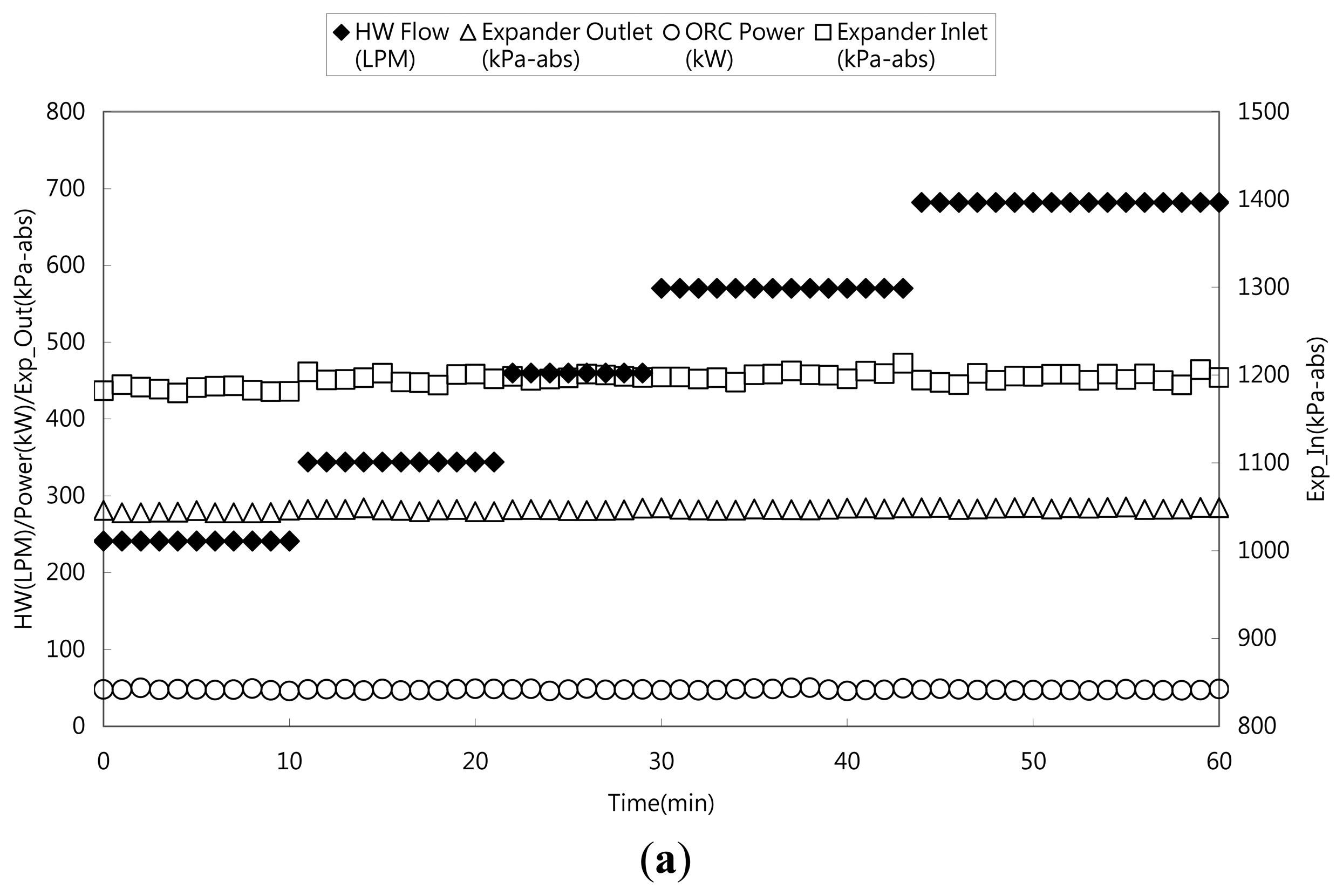
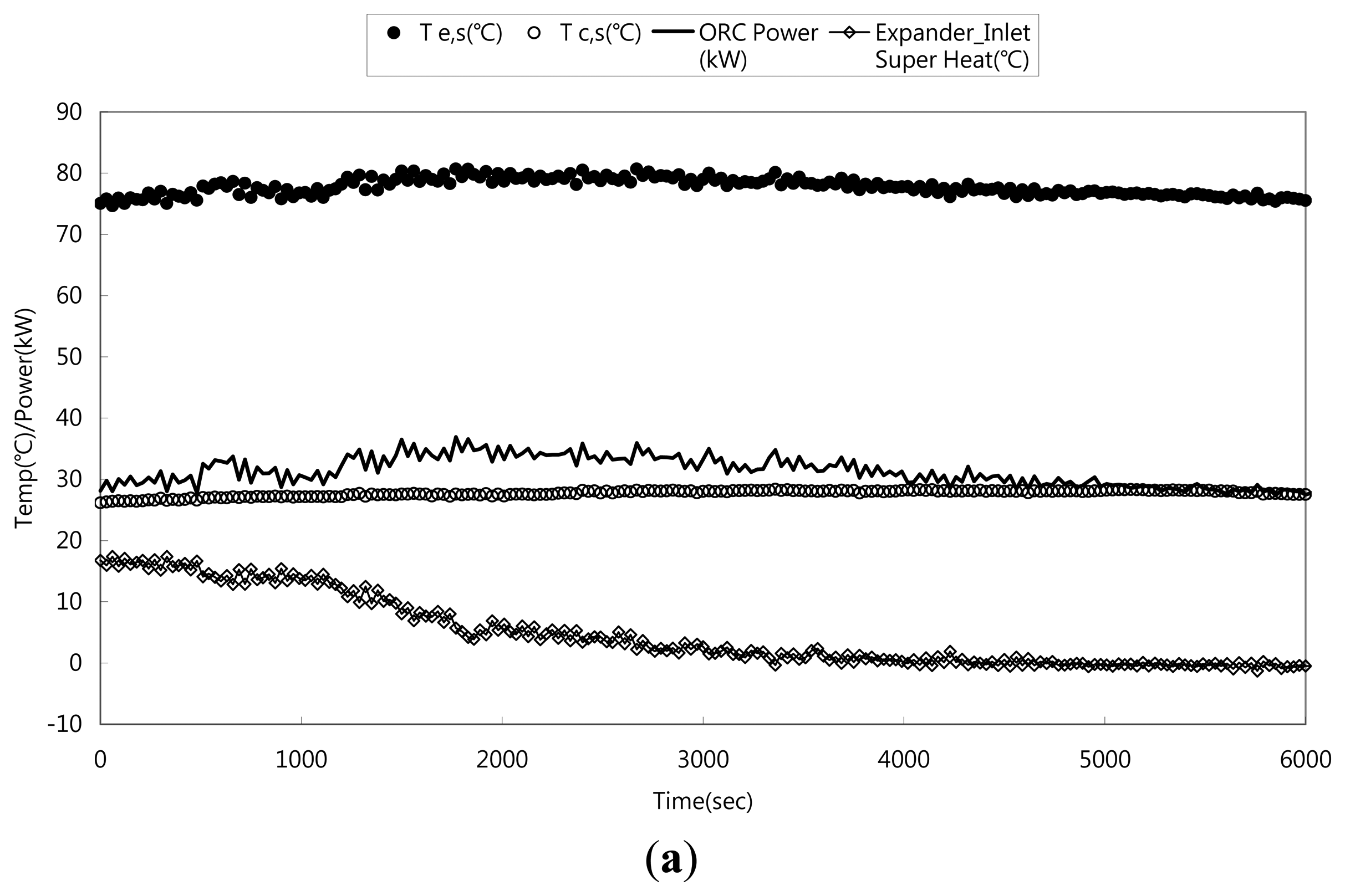
Figure 3 shows the transient system response subject to change of heating water flowrate. The 4-step rise of the flowrate is first raised from 241 to 344 L/min, followed by 460, 570, and finally to 682 L/min. Initially, the hot water flowrate is 241 L/min with an inlet temperature of 125.1 °C. The corresponding changes of ORC power, efficiency, pressures at the inlet and outlet of expander, condensing temperature, and evaporation temperature are shown in Figure 3 subject to the 4-step rise of the water florate. As seen in Figure 3, despite a 2.83 fold increase of flowrate, it appears that the system response is independent of the change of hot water flowrate, as all the major parameters of the ORC system remain relatively unchanged with the change of water flowrate, including the ORC power output, inlet and outlet pressures at the expander, and the condensing and evaporation temperatures. At first glance, the results seem quite confusing, since increasing the flowrate normally give rises to a better heat transfer performance of the evaporator, and accordingly it may result in a higher ORC power output. The effect of heating water flowrate at the evaporator on the system performance is quite the opposite to that of raising cooling water flowrate at the condenser as depicted by Lee et al. [12] who had conducted experiments of a 50 kW ORC system subject to change of coolant flowrate at the condenser. For a 43% increase of coolant flowrate in the condenser, their results showed a moderate 29% increase of ORC power. Yet for an abruptly three-fold rise of coolant flowrate (from 40 L/min to 120 L/min), Lee et al. [12] reported some unexpected peculiar phenomena such as flow surge and power outage phenomena. Based on the explanations from the analysis of Wang and Liao [13], Liao et al. [14], and Liao and Wang [15], the unusual phenomenon is well elaborated and it is mainly associated with gigantic void change in the condenser during the transient process.
However, as mentioned earlier, there is hardly any similarity of the transient response between raising hot water flowrate in the evaporator and increasing the coolant flowrate in the condenser. In fact, a close examination of the variation of the system cycle based on the measuring devices (temperatures and pressures) shows that the system cycle unveils barely any changes as depicted in Figure 4.
To explain the difference between condenser and evaporator, one must realize that there is a corresponding phase density difference in the condenser and evaporator. The density ratio, (ρG/ρL), for R-245fa at P = 300 kPa (condenser) is about 76.8, while the value is significantly reduced to 16.6 when P is raised to 1170 kPa (evaporator). This considerable difference implies that much less volume will be displaced at the evaporator during the phase change process. Secondly, according to a prior analysis (Kuo et al. [16]), the dominant thermal resistance is on the refrigerant side and it accounts for 60%–70% of the total resistance. Hence raising the hot water flowrate will not impose a significant impact on the evaporator. Thirdly, the void change in the evaporator during evaporation is not so pronounced as that in the condenser. The results are also in line with the observation of Beck and Wedekind [17] who performed analysis and experiments on the transient of evaporation and condensing flow. They found that only the condensing flow revealed a flow surge phenomenon during the transient process, whereas the evaporating flow shows a relatively smooth variation subject to perturbation influences like flowrate changes. In summary of the foregoing discussions, the effect of varying hot water flowrate in the evaporator on the ORC system is quite small and can be disregarded. As a consequence, in the practical operation of the ORC system, the hot water flowrate can be kept as small as possible to minimize the pumping power of the refrigerant pump. Note that the power consumption of the fluid pump follows the affinity law which indicates the consumed power is proportional to the flowrate to the cubic power. Therefore, with a lower operating hot water flowrate of 241 LPM, its consumed power is appreciably reduced from 4.8 kW to 0.54 kW. Taking the influence of power consumption on the ORC system, the system efficiency is raised from 7.18% to 8.05% when the flowrate is reduced from 682 LPM to 241 LPM.
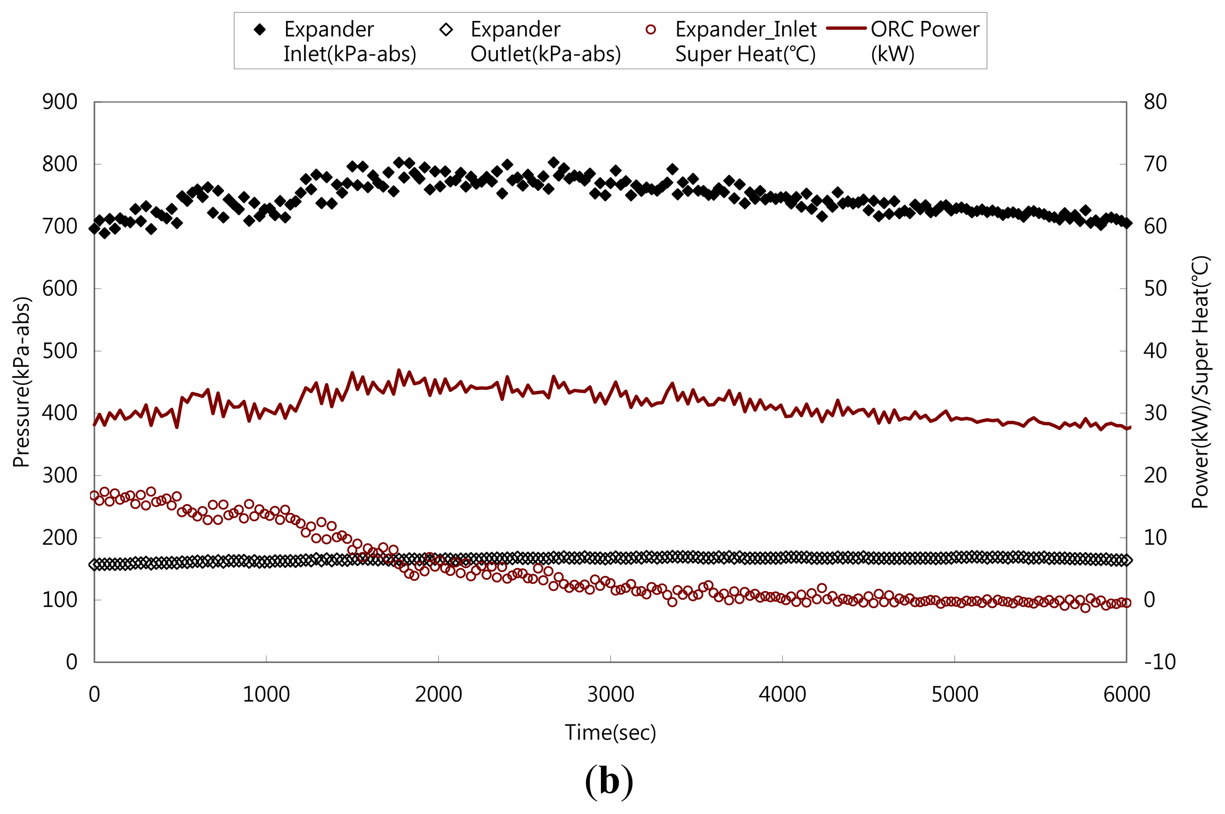
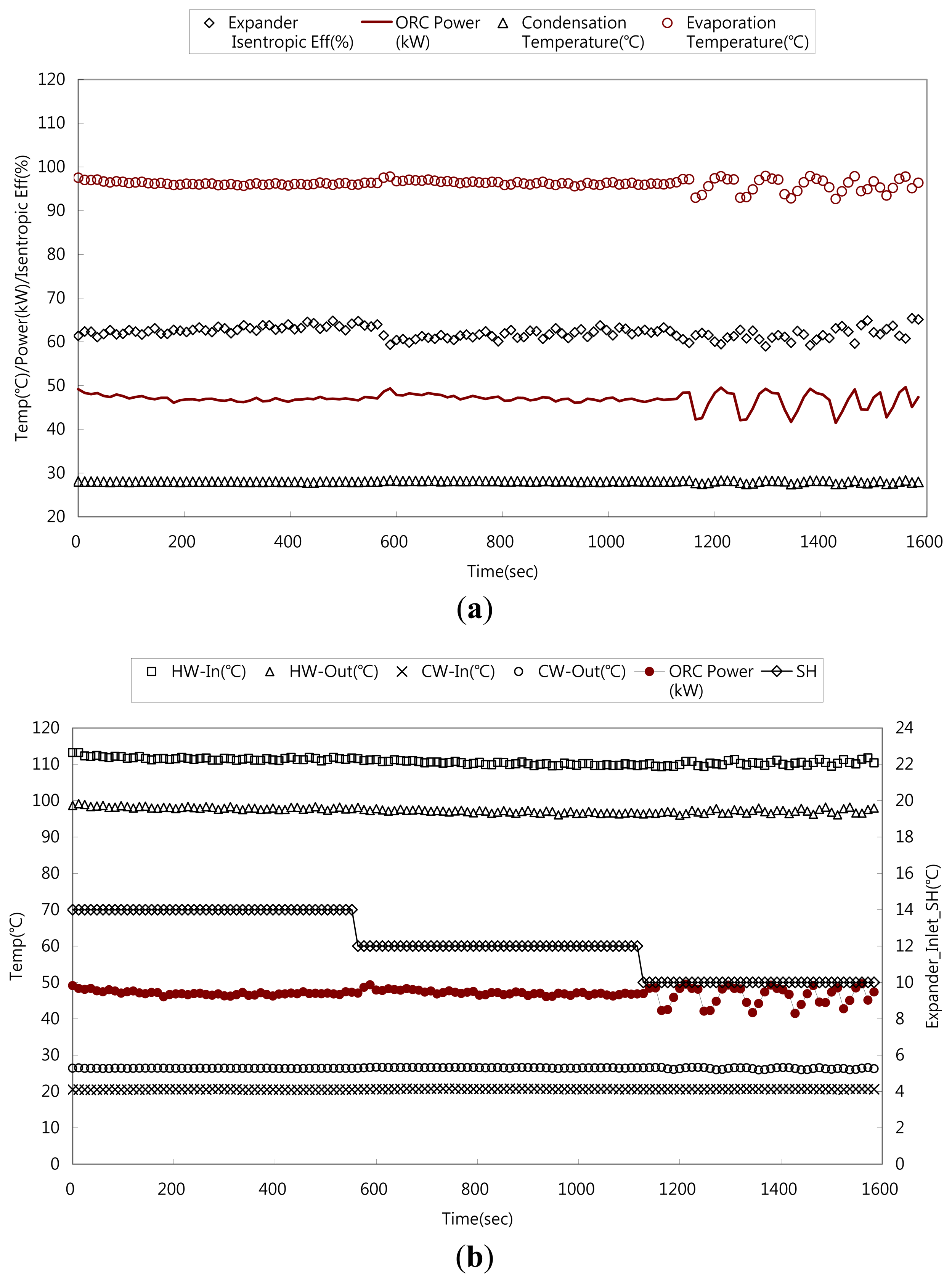
In a typical ORC system, both plate and shell-and-tube heat exchangers can be used as the evaporators. In this study, we have compared the associated system response for these two different heat exchangers subject to the influence of exit superheat. The working fluid, R-245fa, is placed at the shell side of the shell and tube heat exchanger. For the plate heat exchanger, the associated exit superheat level at the outlet is 10, 12, and 14 °C, respectively. Adjustment of the exit superheat is made by regulating the hot water flowrate at the evaporator. As shown in Figure 5, for the plate evaporator, change of exit superheat level from 14 to 12 °C does not result in any detectable influence on the system response, but as the exit superheat is reduced to 10 °C, an unstable oscillation emerges. Both the inlet and outlet pressure of the expander reveal about ±10% unstable fluctuation.
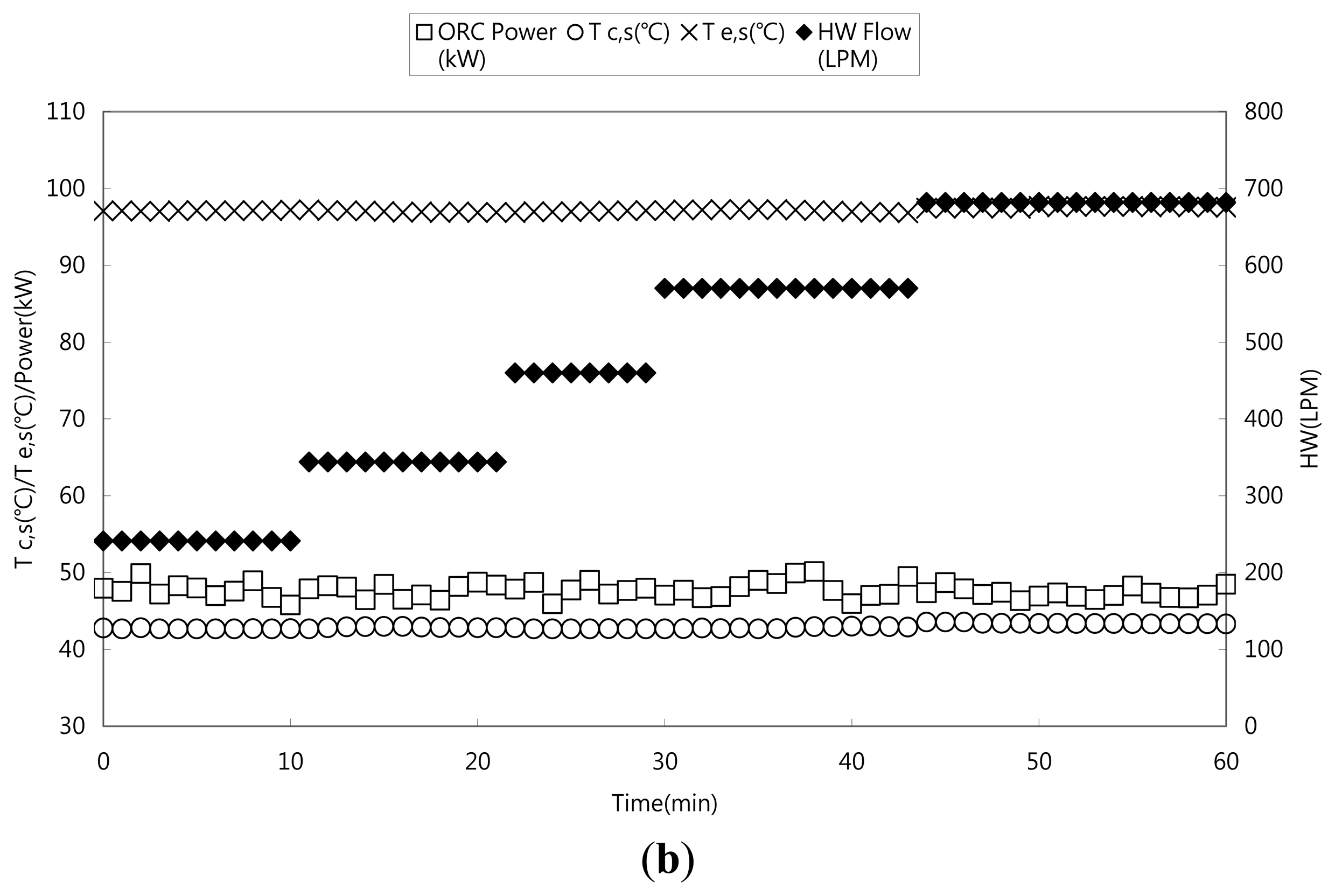
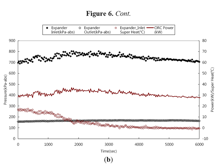
The causes of this phenomenon are associated with the presence of liquid entrainments in low superheat conditions. Barnhart and Peters [18] conducted entrainment measurements for a serpentine evaporator. They found that the entrainment is related to exit superheat, inlet quality, and mass flowrate of the evaporator. Among the aforesaid effects, the exit superheat plays the most critical role on the entrainment flowrate. Their experiments showed that the entrainment fraction is mainly related to the dimensionless Jakob number, . Where ΔT represents the exit superheat (Tg − Ts), cp is the specific heat, and ifg is the corresponding latent heat. Barnhart and Peters [18] found that the entrainment fraction is considerably reduced when Ja is above 0.02. On the other hand, the present results indicate that the influence of entrainment is negligible when Ja is above 0.07. The difference between the present data and theirs is actually not surprising. Firstly, the basic configuration is quite different (horizontally arranged serpentine tube evaporator vs. vertical plate heat exchanger), the serpentine configuration with return bend inevitably reduces the amount of entrainment due to consecutive turnings. Secondly, their horizontal arrangement is also prone to the influence of gravity. In summary, these two effects give rise to the difference in Ja value. In spite of the quantitative difference that prevails between the present one and theirs, the qualitative trend is basically the same that the exit superheat has a significant influence on the instability phenomenon. On the other hand, the exit superheat for the shell-and-tube heat evaporator as shown in Figure 6, ranging from 0–17 °C, does not result in any unstable oscillation of the ORC system. All the major parameters, like condensing pressure (temperature), evaporation pressure (temperature), and ORC system efficiency remain about the same irrespective of any exit superheat. The opposite trend between plate and shell-and-tube heat exchanger is mainly due to the inherent nature of these two kinds of heat exchanger. For the plate heat exchanger, the cross section area remains the same during the evaporation process; thereby the corresponding vapor velocity is sufficient high at the exit of the plate heat exchanger and hence the vapor shear caused by the gigantic density difference leads to liquid entrainment. The results are analogous for the serpentine heat exchanger of Barnhart and Peters [18]. However, the appreciable volume above the tube bundle of the shell-and-tube heat exchanger as shown in Figure 2b acts as an enormous buffer for the evaporated vapor. Therefore the vapor velocity is still too low to carry any significant amount of liquid entrainment into the expander for various exit superheat values. As a result, no unstable oscillation of the ORC system occurs, yet the power output remains fairly steady in association with the exit superheat.
4. Conclusions
In this study, the variations of the evaporator on the system responses of a 50 kW ORC system are reported. The working fluid of the ORC system is R-245fa. First the influence of the flowrate of hot water supplied to the evaporator on a 50 kW ORC is examined. The effect of exit superheat for various types of evaporator, including a plate and shell-and-tube heat exchanger, on the system performance is also reported. Based on the foregoing discussions, the following conclusions are made:
- (1)
The effect of hot water flowrate on the evaporator has a negligible effect on the transient response of the ORC system. These results are true even for a 3.5-fold increase of the hot water flowrate. There is barely any change in the cycle response;
- (2)
As far as system efficiency is concerned, the hot water flowrate can be kept as small as possible;
- (3)
The effect of exit superheat on the ORC system depends of the type of evaporator used. For the plate evaporator, an exit superheat less than 10 °C may cause an unstable ORC system. This is because the liquid entrainment may result in unstable operation of the screw expander. To maintain a stable operation, the corresponding Jakob number of the plate heat evaporator must be above 0.07. On the other hand, no unstable oscillation of the ORC system is observed for exit superheats of 0–17 °C when a shell-and-tube heat exchanger is used as the evaporator. It appears that the sufficiently large buffer above the tube bundle may significantly reduce the effect vapor shear and eliminate the effect of entrainment.
Acknowledgments
The authors would like to express gratitude for the Energy R&D foundation funding from the Bureau of Energy of the Ministry of Economic, Taiwan and Ministry of Science and Technology of Taiwan (NSC-103-2623-E-009-002–ET).
Conflicts of Interest
The authors declare no conflict of interest.
References
- Kang, S.H. Design and experimental study of ORC (organic Rankine cycle) and radial turbine using R245fa working fluid. Energy 2012, 41, 514–524. [Google Scholar]
- Hung, T.; Shai, T.; Wang, S. A review of organic Rankine cycles (ORCs) for the recovery of low-grade waste heat. Energy 1997, 22, 661–667. [Google Scholar]
- Saleh, B.; Koglbauer, G.; Wendland, M.; Fischer, J. Working fluids for low-temperature organic Rankine cycles. Energy 2007, 32, 1210–1221. [Google Scholar]
- Liu, B.T.; Chien, K.H.; Wang, C.C. Effect of working fluids on organic Rankine cycle for waste heat recovery. Energy 2004, 29, 1207–1217. [Google Scholar]
- Chen, H.; Goswami, D.Y.; Stefanakos, E.K. A review of thermodynamic cycles and working fluids for the conversion of low-grade heat. Renew. Sustain. Energy Rev. 2010, 14, 43059–43067. [Google Scholar]
- Vélez, F.; Segovia, J.J.; Martín, M.C.; Antolín, G.; Chejne, F.; Quijano, A. A technical, economical and market review of organic Rankine cycles for the conversion of low-grade heat for power generation. Renew. Sustain. Energy Rev. 2012, 16, 4175–4189. [Google Scholar]
- Wang, X.D.; Zhao, L.; Wang, J.L. Experimental investigation on the low-temperature solar Rankine cycle system using R245fa. Energy Convers. Manag. 2011, 52, 946–952. [Google Scholar]
- Wang, J.L.; Zhao, L.; Wang, X.D. An experimental study on the recuperative low temperature solar Rankine cycle using R245fa. Appl. Energy 2012, 94, 34–40. [Google Scholar]
- Manolakos, D.; Kosmadakis, G.; Kyritsis, S.; Papadakis, G. On site experimental evaluation of a low-temperature solar organic Rankine cycle system for RO desalination. Sol. Energy 2009, 83, 646–656. [Google Scholar]
- Quoilin, S.; Lemort, V.; Lebrun, J. Experimental study and modeling of an Organic Rankine Cycle using scroll expander. Appl. Energy 2010, 87, 1260–1268. [Google Scholar]
- Borsukiewicz-Gozdur, A. Experimental investigation of R227ea applied as working fluid in the ORC power plant with hermetic turbogenerator. Appl. Therm. Eng. 2013, 56, 126–133. [Google Scholar]
- Lee, Y.R.; Kuo, C.R.; Wang, C.C. Transient response of a 50 kW organic Rankine cycle system. Energy 2012, 48, 532–538. [Google Scholar]
- Wang, C.C.; Liao, N.S. Transient response of a double pipe condenser to change of coolant flowrate. Int. Commun. Heat Mass Transf. 1989, 16, 325–334. [Google Scholar]
- Liao, N.S.; Wang, C.C.; Tien, C.L. Analysis of transient flow surge phenomena in a single tube condenser. Int. Commun. Heat Mass Transf. 1988, 15, 257–268. [Google Scholar]
- Liao, N.S.; Wang, C.C. Transient response characteristics of two phase condensing flows. Int. J. Multiph. Flow 1990, 16, 139–151. [Google Scholar]
- Kuo, C.R.; Hsu, S.W.; Chang, K.H.; Wang, C.C. Analysis of a 50 kW Organic Rankine cycle system. Energy 2011, 36, 5877–5885. [Google Scholar]
- Beck, B.T.; Wedekind, G.L. A generalization of the system mean void fraction model for transient two-phase evaporating flows. J. Heat Transf. 1981, 103, 81–85. [Google Scholar]
- Barnhart, J.S.; Peters, J.E. An experimental investigation of entrained liquid carry-over from a serpentine evaporator. Int. J. Refrig. 1995, 18, 343–354. [Google Scholar]


© 2014 by the authors; licensee MDPI, Basel, Switzerland. This article is an open access article distributed under the terms and conditions of the Creative Commons Attribution license( http://creativecommons.org/licenses/by/3.0/).
Share and Cite
Lee, Y.-R.; Kuo, C.-R.; Liu, C.-H.; Fu, B.-R.; Hsieh, J.-C.; Wang, C.-C. Dynamic Response of a 50 kW Organic Rankine Cycle System in Association with Evaporators. Energies 2014, 7, 2436-2448. https://doi.org/10.3390/en7042436
Lee Y-R, Kuo C-R, Liu C-H, Fu B-R, Hsieh J-C, Wang C-C. Dynamic Response of a 50 kW Organic Rankine Cycle System in Association with Evaporators. Energies. 2014; 7(4):2436-2448. https://doi.org/10.3390/en7042436
Chicago/Turabian StyleLee, Yuh-Ren, Chi-Ron Kuo, Chih-Hsi Liu, Ben-Ran Fu, Jui-Ching Hsieh, and Chi-Chuan Wang. 2014. "Dynamic Response of a 50 kW Organic Rankine Cycle System in Association with Evaporators" Energies 7, no. 4: 2436-2448. https://doi.org/10.3390/en7042436
APA StyleLee, Y.-R., Kuo, C.-R., Liu, C.-H., Fu, B.-R., Hsieh, J.-C., & Wang, C.-C. (2014). Dynamic Response of a 50 kW Organic Rankine Cycle System in Association with Evaporators. Energies, 7(4), 2436-2448. https://doi.org/10.3390/en7042436