Article

Electronic Power Transformer Control Strategy in Wind Energy Conversion Systems for Low Voltage Ride-through Capability Enhancement of Directly Driven Wind Turbines with Permanent Magnet Synchronous Generators (D-PMSGs)

School of Electrical & Electronic Engineering, Huazhong University of Science and Technology, Wuhan 430074, Hubei, China
*
Author to whom correspondence should be addressed.
Energies 2014, 7(11), 7330-7347; https://doi.org/10.3390/en7117330
Submission received: 18 September 2014 / Revised: 3 November 2014 / Accepted: 3 November 2014 / Published: 14 November 2014
(This article belongs to the Special Issue Wind Turbines 2014)

Abstract

:
This paper investigates the use of an Electronic Power Transformer (EPT) incorporated with an energy storage system to smooth the wind power fluctuations and enhance the low voltage ride-through (LVRT) capability of directly driven wind turbines with permanent magnet synchronous generators (D-PMSGs). The decoupled control schemes of the system, including the grid side converter control scheme, generator side converter control scheme and the control scheme of the energy storage system, are presented in detail. Under normal operating conditions, the energy storage system absorbs the high frequency component of the D-PMSG output power to smooth the wind power fluctuations. Under grid fault conditions, the energy storage system absorbs the redundant power, which could not be transferred to the grid by the EPT, to help the D-PMSG to ride through low voltage conditions. This coordinated control strategy is validated by simulation studies using MATLAB/Simulink. With the proposed control strategy, the output wind power quality is improved and the D-PMSG can ride through severe grid fault conditions.

1. Introduction

With the increasing urgency of both energy crisis and environmental pollution, there is a pressing urgent need to find alternative fuel sources which are clean, environmental-friendly and reproducible. Wind power is assumed to offer the most favorable technical and economic prospects in this respect, and is the most rapidly growing one among the various renewable energy sources [1,2].
There are mainly two kinds of wind power generators in wind farms, directly driven wind turbines with permanent magnet synchronous generators (D-PMSGs) and doubly fed induction generators (DFIGs). The D-PMSG type has gained much attention in wind power generation recently due to its advantages such as lower mechanical consumption, higher efficiency and energy yield, higher reliability, higher power to weight ratio and easier maintenance, compared with DFIGs [3]. However, the intermittent and fluctuant active power output of wind farms will have different impacts on various aspects of the power system, such as power quality, frequency control, voltage support, system reserve capacity, etc. especially under grid fault conditions, and if the wind power generators trip offline for self-protection, this will deteriorate the grid conditions and make the grid more difficult to recover [4]. To address these issues, on the one hand, wind farms generally need to install reactive power compensation devices, such as Static VAR (volt ampere reactive) compensators (SVCs), static compensators (STATCOMs) etc., for wind generators to provide quick reactive power compensation and grid voltage support [5,6,7]; on the other hand, some control strategies based on the wind turbine pitch angle control or energy storage system have been proposed to smooth the wind power fluctuations or enhance the low voltage ride-through (LVRT) capability of wind generators [8].
As a multiple-functional FACTS (flexible alternating current transmission system) devices with the basic functions of the conventional power transformer [9], electronic power transformer (EPT), also called power electronic transformer (PET) [10,11] or solid-state transformer (SST) [12], have been attracting much attention from both academia and industry. On the one hand, a number of recent investigations have been done on the circuit topology design, and establishing the mathematical model and control strategy design of EPTs [13,14,15,16,17]. On the other hand, efforts are focusing on the applications of EPTs in areas where conventional power transformers are dominating, such as solar farms, wind farms, charge stations and smart grids [18,19,20,21,22,23]. In [20], a family of wind energy systems with integrated functions of active power transfer, reactive power compensation, and voltage conversion were proposed. In [21] researchers put forward a new D-PMSG grid-connected system based on SST, and a crowbar circuit was add to the DC (direct current) bus to enhance the LVRT capability of the D-PMSG.
In all the previous applications of EPT in wind farms, only the benefits of voltage conversion, reduced volume and weight, decoupling control of active and reactive power, and reactive power compensation were considered. Although it is known that EPTs incorporated with energy storage systems could smooth wind power fluctuations and enhance the LVRT capability of wind generators, to the best of the authors’ knowledge, no literature has explored EPTs in these applications.
This paper investigates the use of EPTs incorporated with energy storage systems to smooth the wind power fluctuations and enhance the LVRT capability of D-PMSGs. The EPT control schemes for wind power fluctuation smoothing and LVRT capability enhancement are presented in detail. Case studies during wind speed increase, normal conditions, unbalanced grid voltage conditions and three phase ground fault conditions are conducted to verify the effectiveness of the proposed control strategy using MATLAB /Simulink.

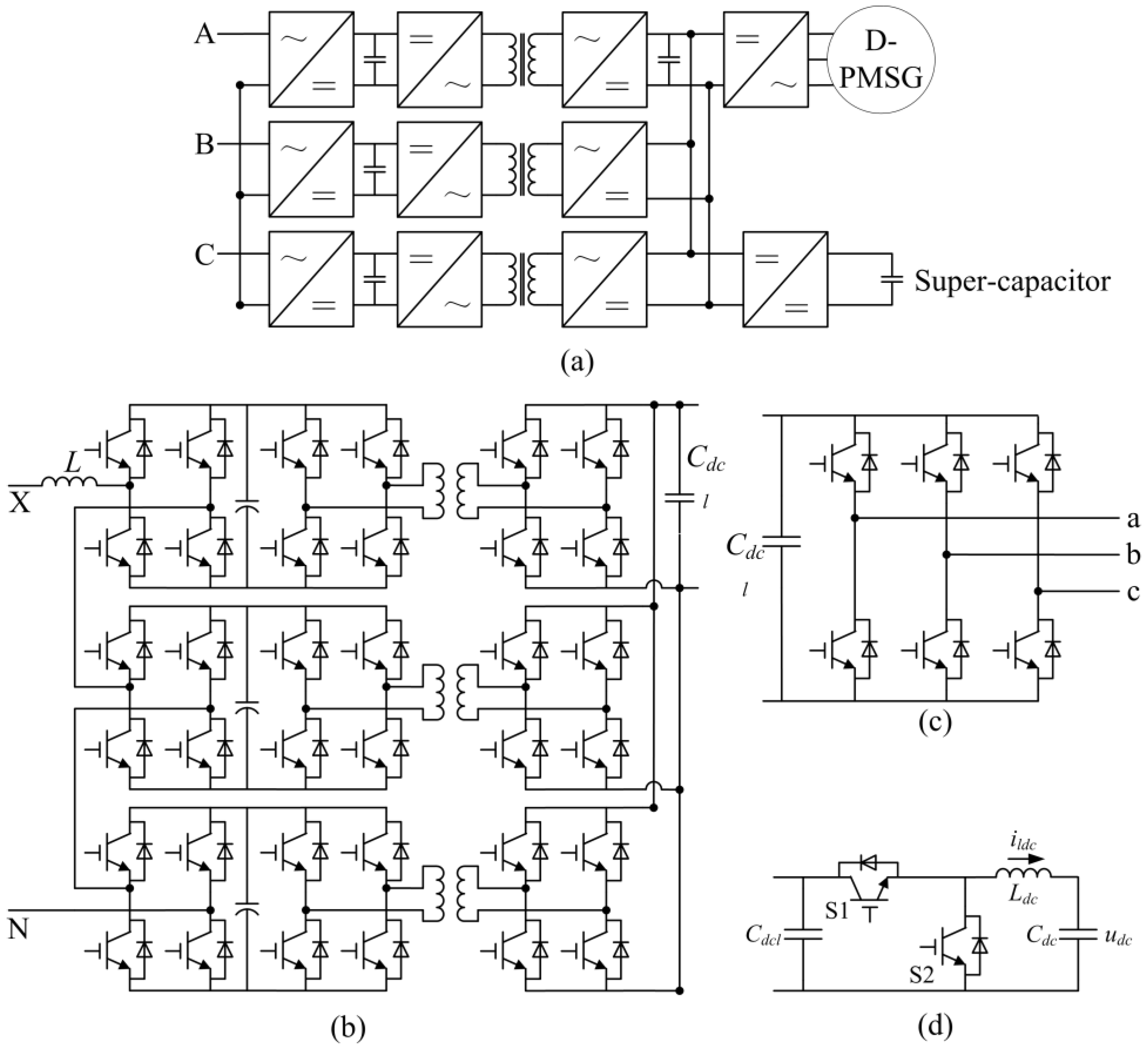
2. System Description and System Model

The configuration for the EPT considered in this work is presented in Figure 1, where the D-PMSG is connected to the grid network via an EPT, which is equipped with a super-capacitor energy storage system. The EPT is a three-stage design that includes a generator side stage, an isolation stage and a high voltage side stage (grid side stage). The generator side voltage source converter (VSC) controls the speed of the generator according to a maximum power point tracking (MPPT) algorithm, to extract the maximum amount of power with the actual wind force, the grid side VSC operates as an inverter to keep the generator side DC bus voltage constant. Considering the high grid AC (alternating current) voltage, a cascaded H-bridge topology is used for the high voltage stage. The isolation stage consists of nine DC/DC converters connected in parallel on the secondary side. The two H-bridge converters and a medium frequency transformer (MFT) in each DC/DC converter constitute a medium-frequency modulating-demodulating block for voltage transformation and isolation, the DC voltage is modulated to a medium-frequency square wave by one of the H-bridge, then coupled to the secondary by the MFT, and reconverted into DC voltage via the other H-bridge. The energy storage system is connected to the EPT generator side DC bus via a DC/DC converter.
Figure 1. Topology of the system. (a) Basic diagram of the system; (b) Single phase topology of the high voltage side and isolation stage converters; (c) Topology of the generator side 3 phase converter; and (d) Topology of the DC/DC converter.
Energies 07 07330 g001

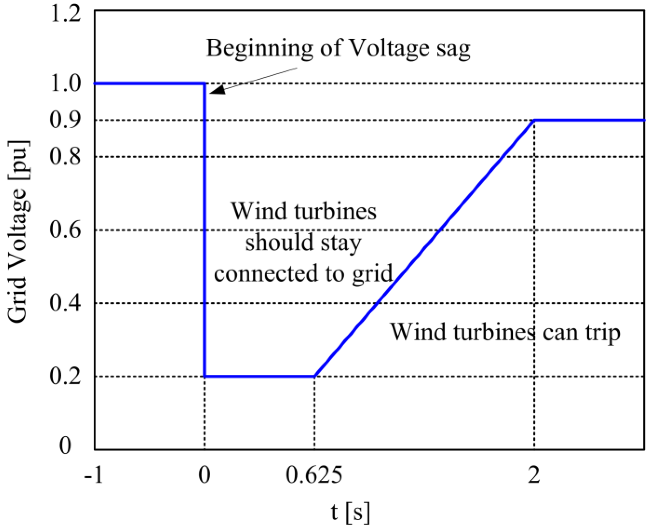
2.1. Low Voltage Ride through Requirement

Nowadays most grid codes require LVRT capability from large wind power plants. This means that they have to remain connected to the network during faults. Figure 2 gives the latest LVRT requirements in China. Wind turbines must remain connected to the network for voltages above the curve and may be disconnected otherwise.
Figure 2. The LVRT (low voltage ride-through) requirements in China.
Energies 07 07330 g002

2.2. Mechanical Drive Train Model

The output mechanical power of the wind turbine is given by the following algebraic Equation (1):
{ P m = 1 2 π ρ R 2 v w 3 C p ( λ , β ) λ = ω r R / v w
where Pm is the extract mechanical power; ρ is the air density; R is the turbine radius; vw is the wind speed; ωr is the mechanical angular velocity of the generator; Cp is the power coefficient, which is a function of tip speed ratio λ and blade angle β. The tip speed ratio λ is given by Equation (1) and the blade angle β is controlled by the pitch angle controller. A two-mass shaft model [24] is used to represent torsional oscillations in the drive train.

2.3. PMSG Model

The PMSG model in the d-q frame can be described by the following equations (Ld = Lq in this paper which corresponds to a non-salient machine):
{ v d = R s i d + L d d i d dt ω e L q i q v q = R s i q + L q d i q dt + ω e L d i d + ω e ψ m T e = 3 2 n p ψ m i q J d ω m dt = T m T e f B ω r
where vd, vq and id, iq are stator voltages and currents in the d-q frame respectively; Rs is the stator resistance; Ld, Lq are inductances in the d-q frame; ωe, ωr are machine electrical and mechanical speed; Te, Tm are the machine electro-magnetic torque and the turbine mechanical torque respectively; np is the machine pole pair number; ψm is the flux linkage created by the rotor permanent magnets; J is the total system inertia and fB is the friction coefficient associated to the mechanical drive train.

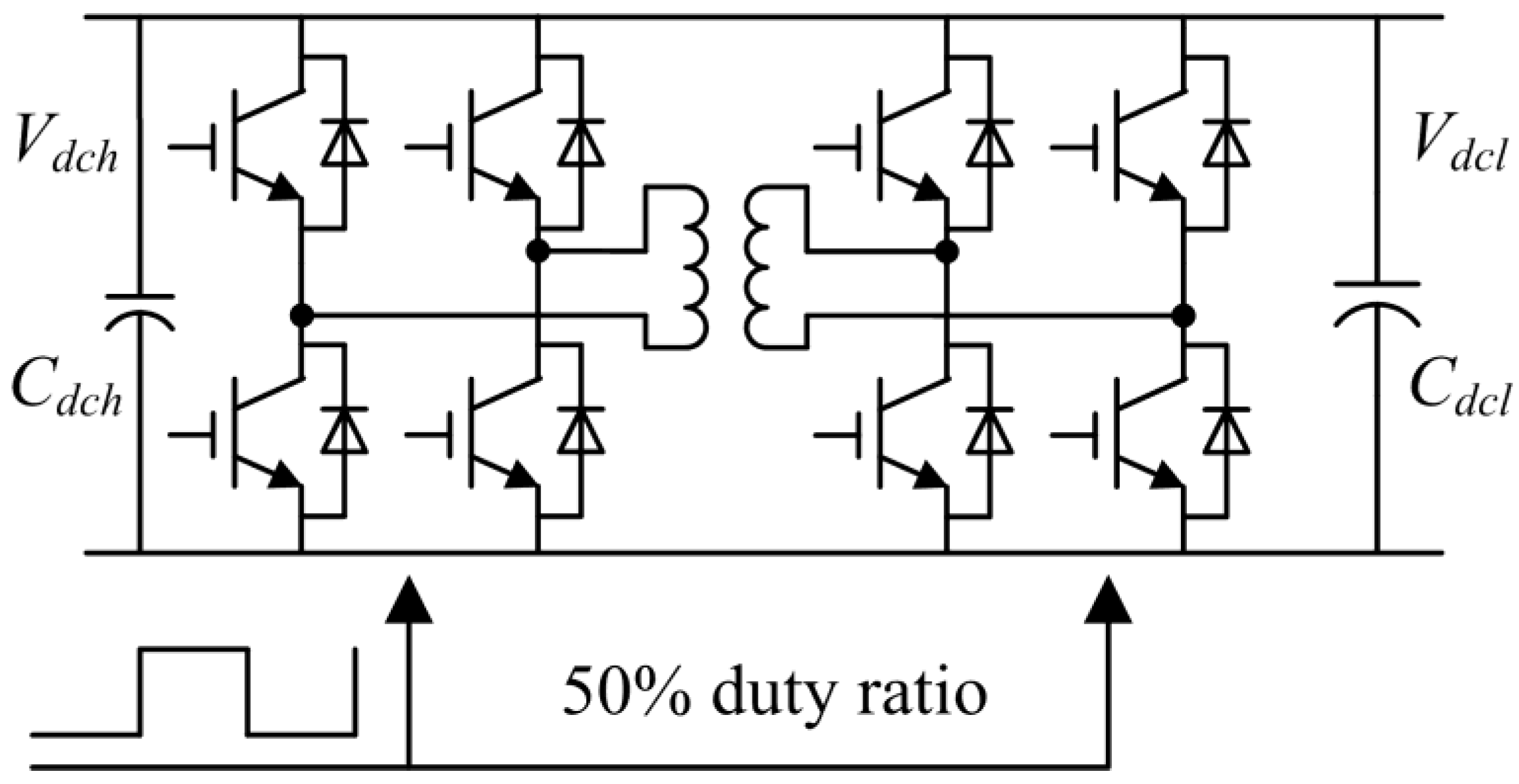
2.4. The Isolation Stage Model

For the isolation stage, the amount and direction of the active power flow, presented in Equation (3) is determined by the phase-shift angle between the two AC square-wave signals [25]:
P O = V dch m V dcl 2 π f T L T φ ( 1 | φ | π )
where PO is the average power through the transformer; Vdch and Vdcl are the capacitor DC voltages; φ is the phase-shift angle between the two AC square-wave signals; m is the high frequency transformer ratio; fT is the switching frequency; and LT is the transformer leakage inductance referred to the secondary side.

2.5. Grid Side VSC Model

During grid fault conditions, the unbalanced three-phase grid voltage can be represented as the orthogonal sum of positive and negative sequences. The dynamics of the grid side VSC can be written in positive and negative d-q frame as follows [26]:
{ u d P = R i d P + L d i d P d t ω L i q P + v d P u q P = R i q P + L d i q P d t + ω L i d P + v q P u d N = R i d N + L d i d N d t ω L i q N + v d N u q N = R i q N + L d i q N d t + ω L i d N + v q P
where u d P ,   u q P   u d N ,   u q N and i d P ,   i q P   i d N ,   i q N are positive and negative sequences of the grid voltages and currents in the d-q frame respectively; v d P ,   v q P   v d N ,   v q N are positive and negative sequences of the VSC pole voltage, which are generated by converter switches; R and L are the resistance and inductance of the VSC linked inductor; ω is the grid voltage frequency.
With the unbalanced input voltage, the power transferred to the grid is presented as follows:
[ P T 0 P T s 2 P T c 2 Q T 0 Q T s 2 Q T c 2 ] = [ u d P u q P u d N u q N u q N u d N u q P u d P u d N u q N u d P u q P u q P u d P u q N u d N u d N u q N u d P u q P u q N u d N u q P u d P ] [ i d P i q P i d N i q N ]
where PT0 and QT0 are the mean active and reactive power, PTs2 and QTs2 are the sine components of the second harmonic active and reactive power, PTc2 and QTc2 are the cosine components of the second harmonic active and reactive power.

2.6. DC/DC Converter Model

The DC/DC converter presented in Figure 1d has two operation modes: Buck and Boost. By triggering insulated-gate bipolar transistors (IGBT) S1, the converter works in Buck mode and energy is transferred from the EPT low voltage side capacitor to the energy storage system. By triggering IGBT S2, the converter works in Boost mode and energy is transferred from the energy storage system to the EPT low voltage side capacitor. The dynamic model of the converter is presented as follows:
{ L dc d i ldc d t = u pwm u sc C sc d u sc d t = i ldc
where Ldc is the inductance of the inductor, Csc is the capacitance of the super-capacitor stack, ildc is the current of the inductor, usc is the voltage of the super-capacitor stack, upwm is the voltage of IGBT S2.

3. Control Strategy of the System

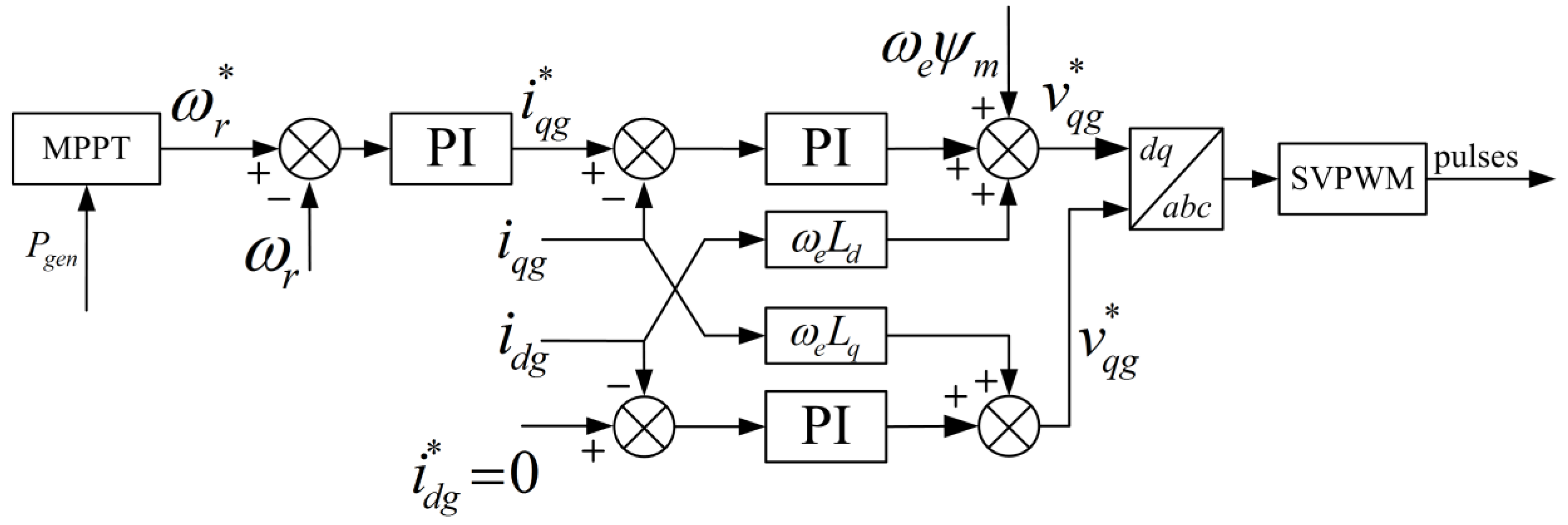
3.1. Control Strategy of the Generator Side Converter

The main purpose of the generator side converter is to extract the maximum amount of power with the actual wind force, and the control strategy of the generator side converter is presented in Figure 3.
Figure 3. Control strategy of the generator side converter.
Energies 07 07330 g003
The outer control loop is the speed loop while the inner control loop is the current control loop [27]. In the outer speed loop, the speed reference is given by a MPPT algorithm presented in Equation (7) [28], where Pgen is output power of D-PMSG. The q axis reference current i qg * is obtained when the speed control error is adjusted by a PI (proportional integral) controller. The d axis reference current i dg * is set to zero:
ω r * = { 1.2 P gen 0.46 0.67 P gen 2 + 1.42 P gen + 0.51 P gen < 0.46

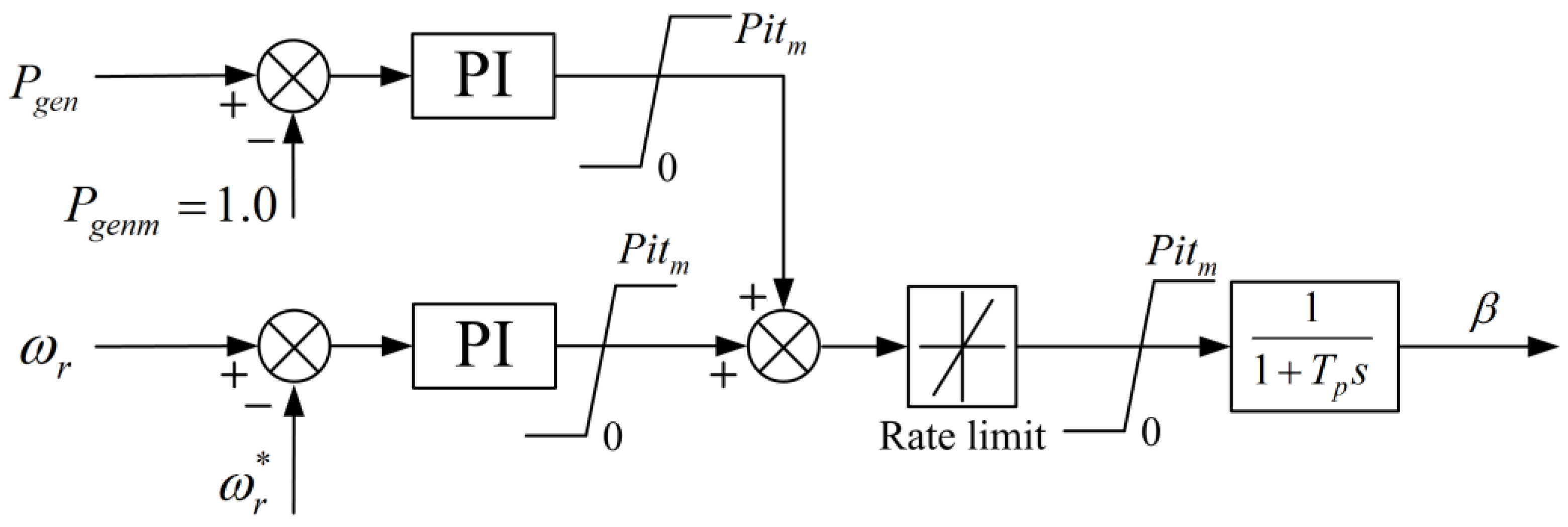
3.2. Wind Turbine Pitch Angle Controller

The control strategy of the turbine pitch angle is depicted in Figure 4. The main purpose of the pitch angle controller is that when the available wind power is above the equipment rating (1.0 pu.), the blade pitch angle controller increases the pitch angle to limit the mechanical power delivered to the shaft to the equipment rating, and when the available wind power is less than equipment rating, the blades are set at minimum pitch to maximize the mechanical power [29].
Figure 4. Control strategy of the turbine pitch angle.
Energies 07 07330 g004

3.3. Control Strategy of the Isolation Stage

The two H-bridges of the isolation stage operate at fixed 50% duty ratio and the frequency of the H-bridges drive signal is 2 kHz. The control block diagram is shown in Figure 5.
Figure 5. Control strategy of the isolation stage converter.
Energies 07 07330 g005

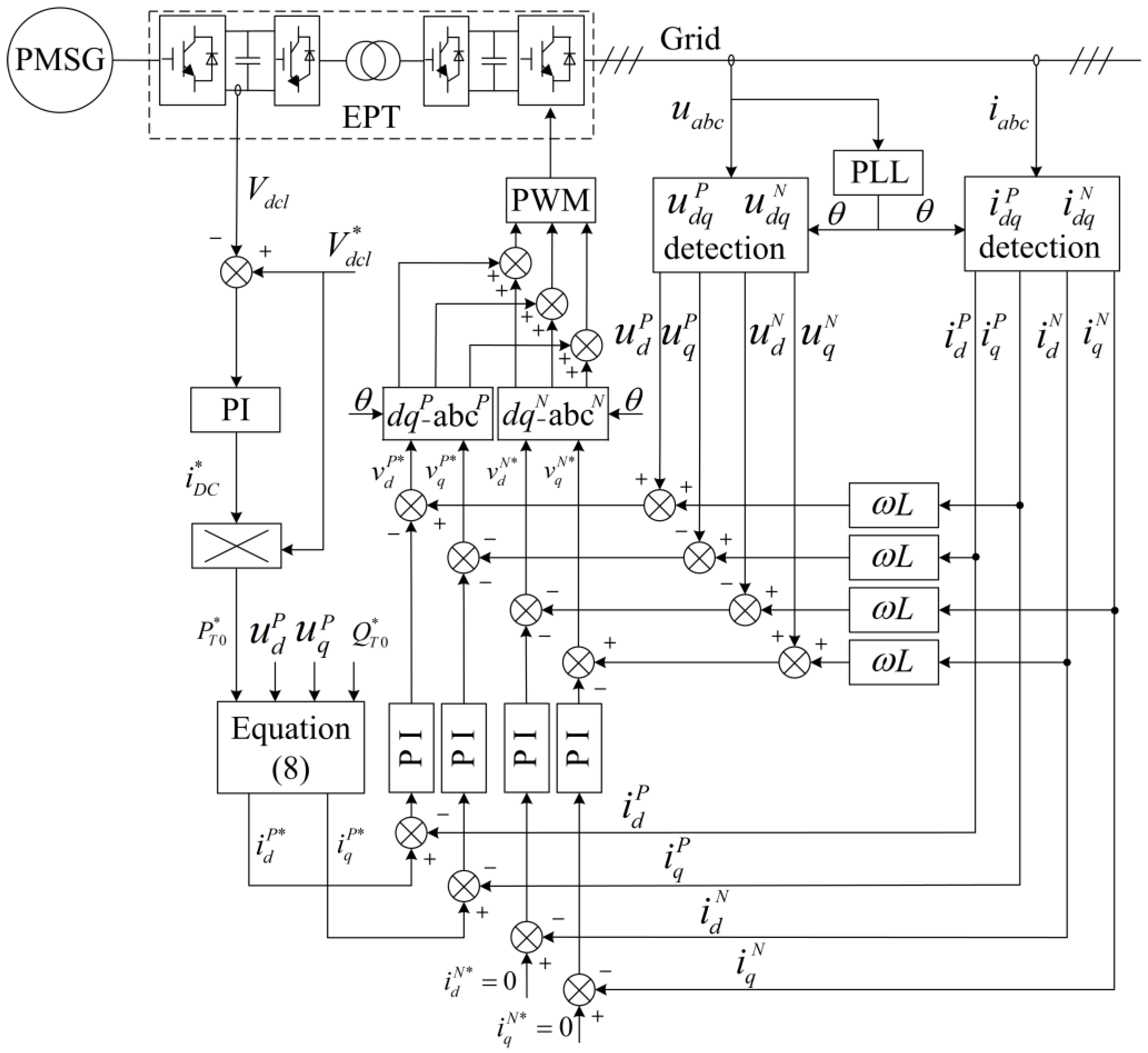
3.4. Control Strategy of the Grid Side Converter

During grid fault conditions, voltage unbalance causes performance deterioration of a pulse width modulation (PWM) converter by producing 100-Hz voltage ripples in the dc link and by increasing the reactive power [30]. To eliminate the negative sequence currents and the dc component of the reactive power, a dual current control scheme is introduced to control both positive and negative sequence currents [26], as shown in Figure 6, where the positive sequence voltage and current are measured in the positive synchronous reference frame (SRF) by eliminating the negative sequence with a 100-Hz notch filter, and the negative sequence voltage and current are measured in the negative SRF. The DC current reference i DC * is determined by the DC-link voltage controller, and the output active power command P To * is obtained by multiplying the DC-link voltage and the output of the DC voltage controller. As the grid side controller has to control the negative sequence currents and the DC component of the reactive power, in this paper the command values of these components are set to zero. Hence with Equation (5), the positive sequence current command i d P* and i q P* are obtained as follows:
{ i d P* = ( u d P ) 2 ( u d P ) 2 + ( u q P ) 2 P T 0 * i q P* = ( u q P ) 2 ( u d P ) 2 + ( u q P ) 2 P T 0 *
where ( u d P ) 2 + ( u q P ) 2 0 is assumed.
PI regulators are introduced to independently control the positive and negative sequence currents in the positive SRF and negative SRF. In positive SRF, the positive sequence converter pole voltages is calculated in Equation (9), and the negative sequence converter pole voltages are calculated in Equation (10) in negative SRF:
{ V d P* = ( K P + K i S ) ( i d P* i d P ) + u d P + ω L i q P V q P* = ( K P + K i S ) ( i q P* i q P ) + u q P ω L i d P
{ V d N* = ( K P + K i S ) ( i d N* i d N ) + u d N ω L i q N V q N* = ( K P + K i S ) ( i q N* i q N ) + u q N + ω L i d N

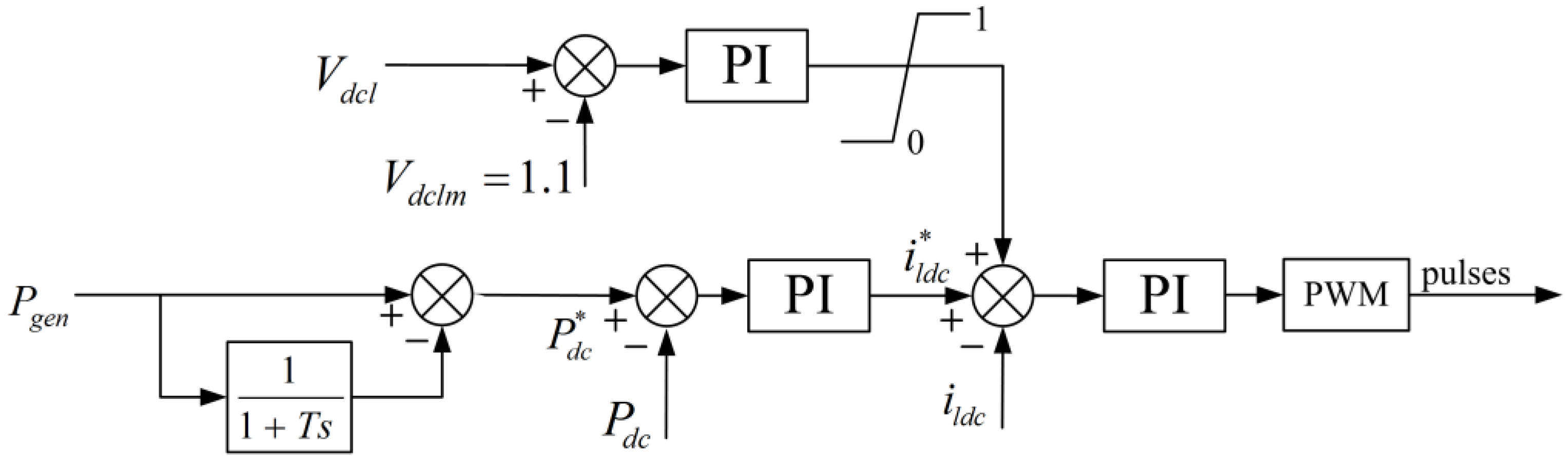
3.5. Control Strategy of the Energy Sorage System

The control strategy of the energy storage system is presented in Figure 7. The outer control loop is the power loop while the inner control loop is the current control loop. Under normal conditions, the energy storage system smoothes the power injected to the grid by absorbing the relatively high frequency components of the D-PMSG output power, and its reference power is calculated by submitting the output power of D-PMSG to a filter.
Figure 6. Control strategy of the grid side converter.
Energies 07 07330 g006
Figure 7. Control strategy of the DC/DC converter.
Energies 07 07330 g007
During grid fault conditions, the generator side converter works to extract maximum amount of power from the wind while the power transferred to the grid is limited as the grid side converter current is limited by its current controller, this may cause the DC-link voltage increase and may damage the DC capacitance. Using the proposed control strategy shown in Figure 7, the DC-link voltage is limited to 1.1 pu as a supplementary controller is add to the current control loop to prevent the DC capacitance from overvoltage and the redundant power is absorbed by the energy storage system.

4. Simulation Results

A simulation model is built in Matlab/Simulink to verify the effectiveness of the proposed control strategy. The D-PMSG parameters are: J = 33,000 kg·m2; ψm = 1.245 Wb; p = 48; Rs = 0.01 Ω; Ld = Lq = 8.35 mH; The rated power is 1.5 MVA; the rated output wind speed is 12 m/s. The 1.65 MVA 690 V/10 kV EPT parameters are: R = 0.0001 Ω; L = 20 mH; Cdch = 6400 μF; Cdc2 = 27.2 mF; The generator side converter switching frequency: (fs)ac/dc = 4 kHz; The isolation stage converter frequency: (fs)dc/dc = 2 kHz; The grid side converter switching frequency: (fs)dc/ac = 5 kHz. The medium frequency transformer ratio is 1500 V/3300 V. The rated capacity of the 600 V super-capacitor stack is 1.5 MVA/1 MWh. The smoothing period is seconds and the time constant in Figure 7 for calculating the reference super-capacitor stack power is 50 s.

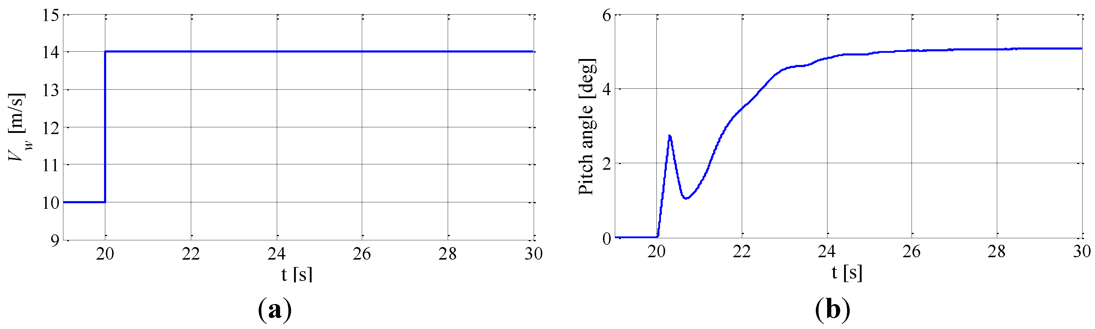
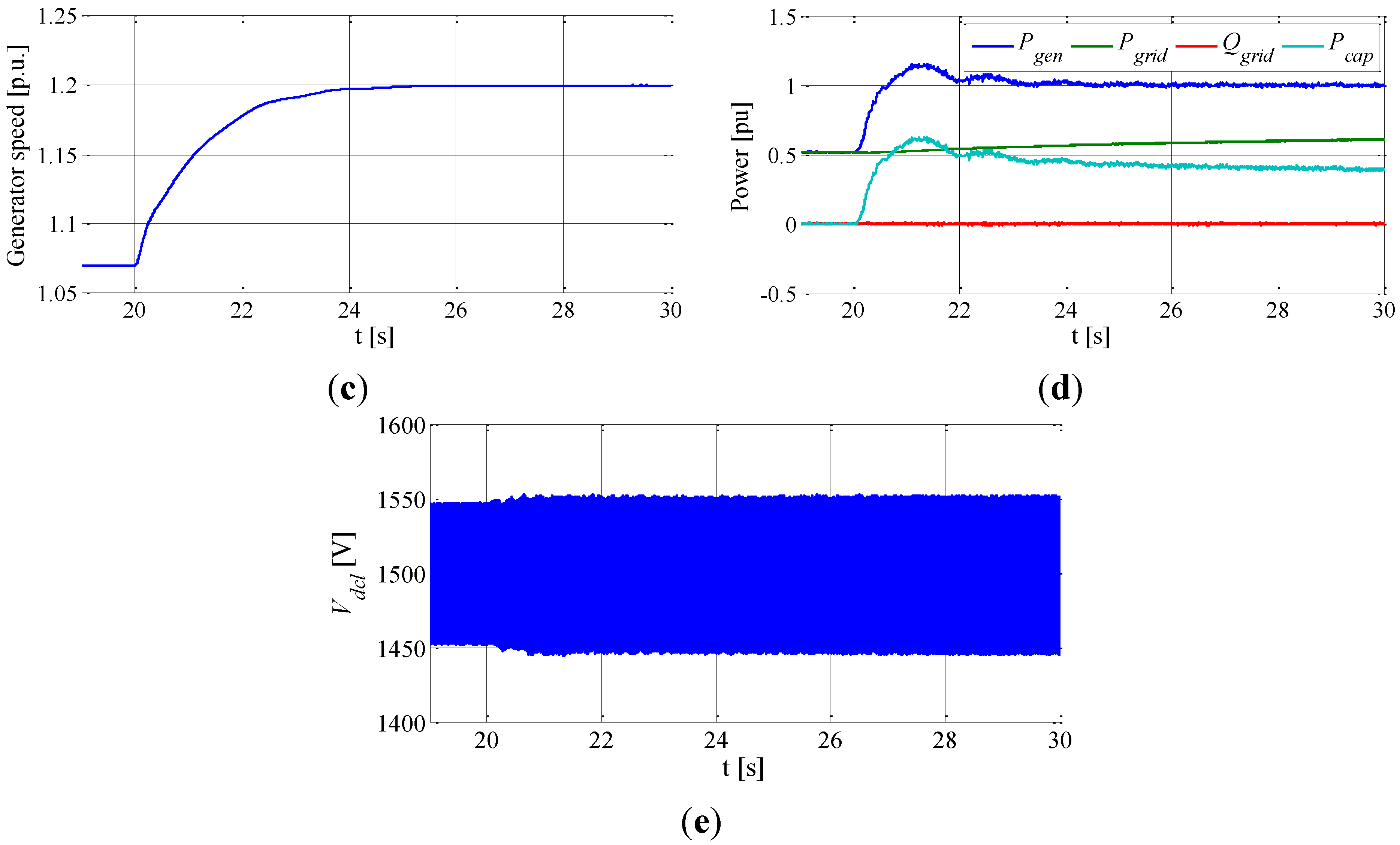
4.1. Response to Wind Speed Step up

A step change of wind speed is applied to the system to test the dynamic performance of the whole system. Figure 8 shows the response of the system to a step change of wind speed Vw, which changes from 10 to 14 m/s at 20 s. As the rated output wind speed is 12 m/s, before the wind speed changes, the generator output power is less than 1.0 pu and the pitch angle is nearly 0°. After the wind speed changes to 14 m/s, the pitch controller adjusts the pitch angle to 5.07° to keep the generator speed at 1.2 pu and the output power at 1.0 pu, as shown in Figure 8b–d. As shown in Figure 8d, the D-PMSG output power Pgen increase from 0.523 to 1.0 pu in less than 2 s after the wind speed steps, while the power transferred to the grid Pgrid increases more slowly and the redundant power is absorbed by the super-capacitor stack, the reactive power transferred to the grid by EPT is kept at 0 pu during all the simulation time. The low voltage side DC voltage presented in Figure 8e is kept constant during the simulation time.
Figure 8. Simulation results of wind speed step up. (a) Wind speed; (b) Pitch angle; (c) Generator speed; (d) Power of D-PMSG EPT and super-capacitor; and (e) EPT low voltage side DC voltage.
Energies 07 07330 g008aEnergies 07 07330 g008b

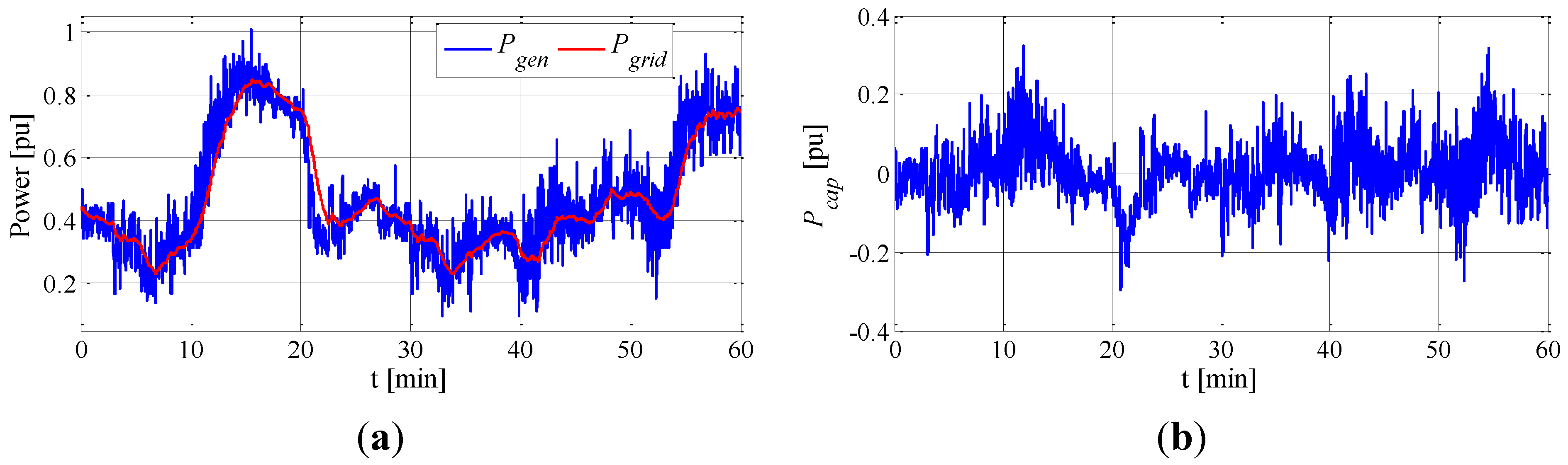
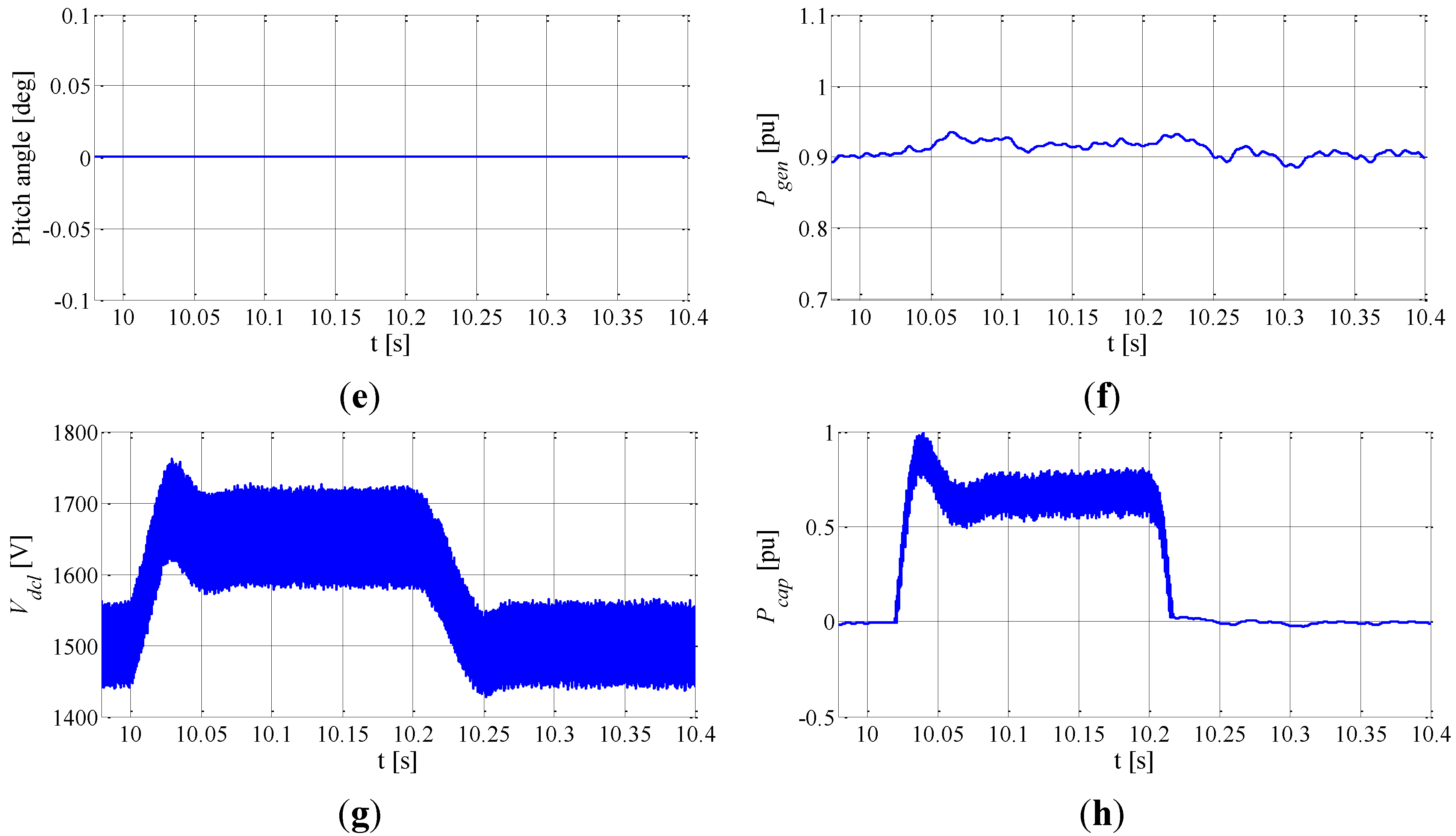
4.2. Simulation Results under Normal Conditions

Under normal conditions, the energy storage system smoothes the power injected to the grid by absorbing the relatively high frequency components of the D-PMSG output power. Wind power with turbulence is used to test the power smoothing performance of the energy storage system under normal conditions, where the active power data of the D-PMSG is obtained from a wind farm located in central China. The D-PMSG output power Pgen, the power transferred to the grid Pgrid and the power absorbed by the super-capacitor stack Pcap are presented in Figure 9. Figure 9a is a comparison of real D-PMSG output power and smoothed power profiles. It can be seen from Figure 9 that the D-PMSG output power is smoothed by the super-capacitor stack.
Figure 9. Simulation results under normal conditions (a) D-PMSG output power and the power transferred to the grid; (b) Power transferred to the super-capacitor stack.
Energies 07 07330 g009

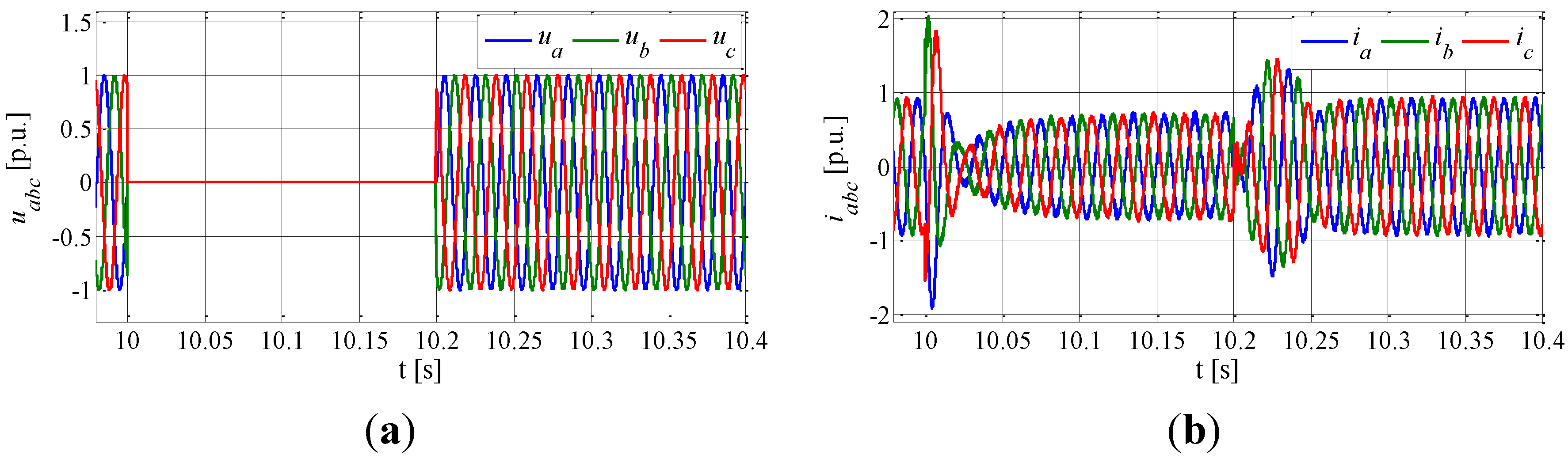
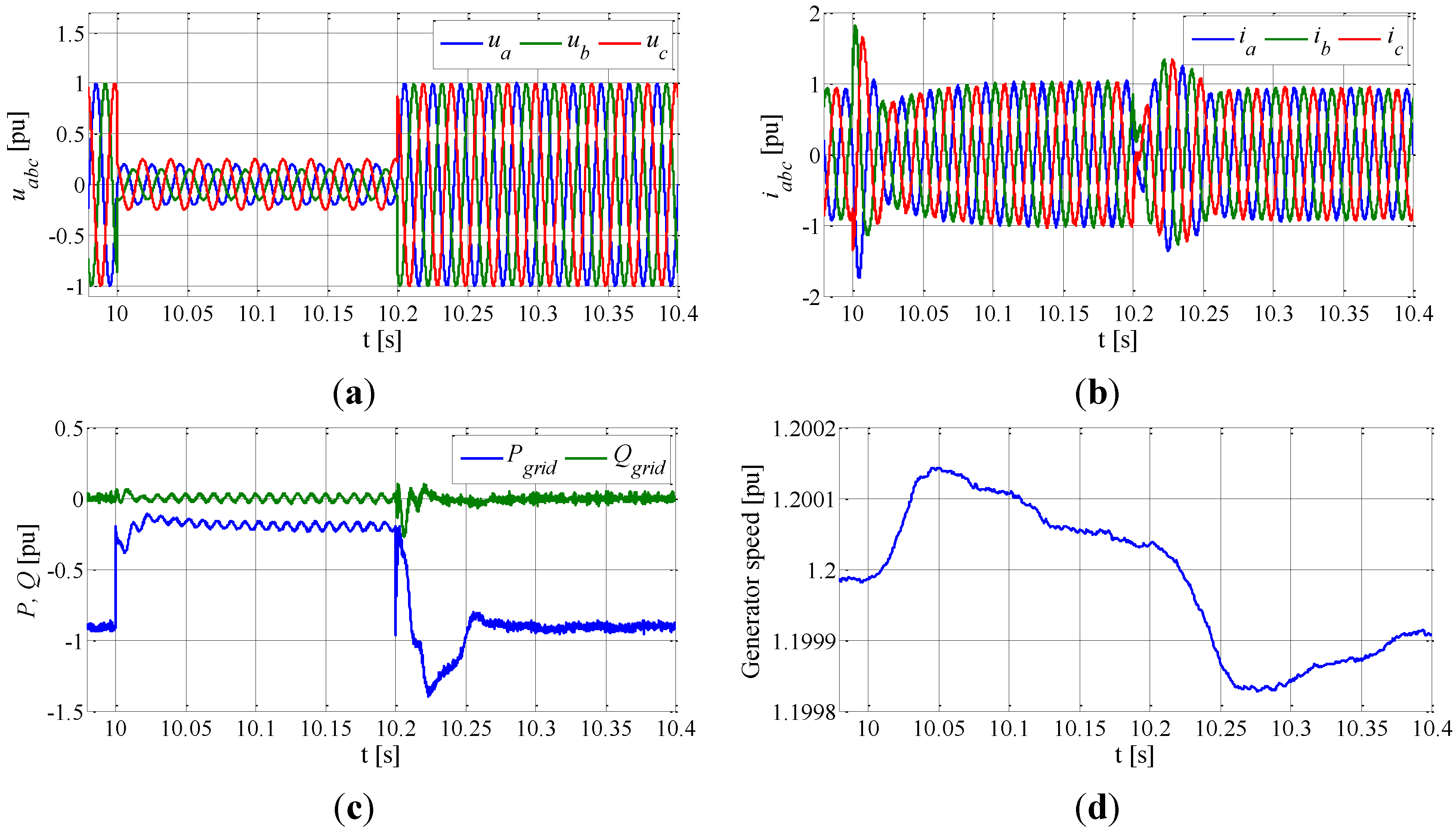
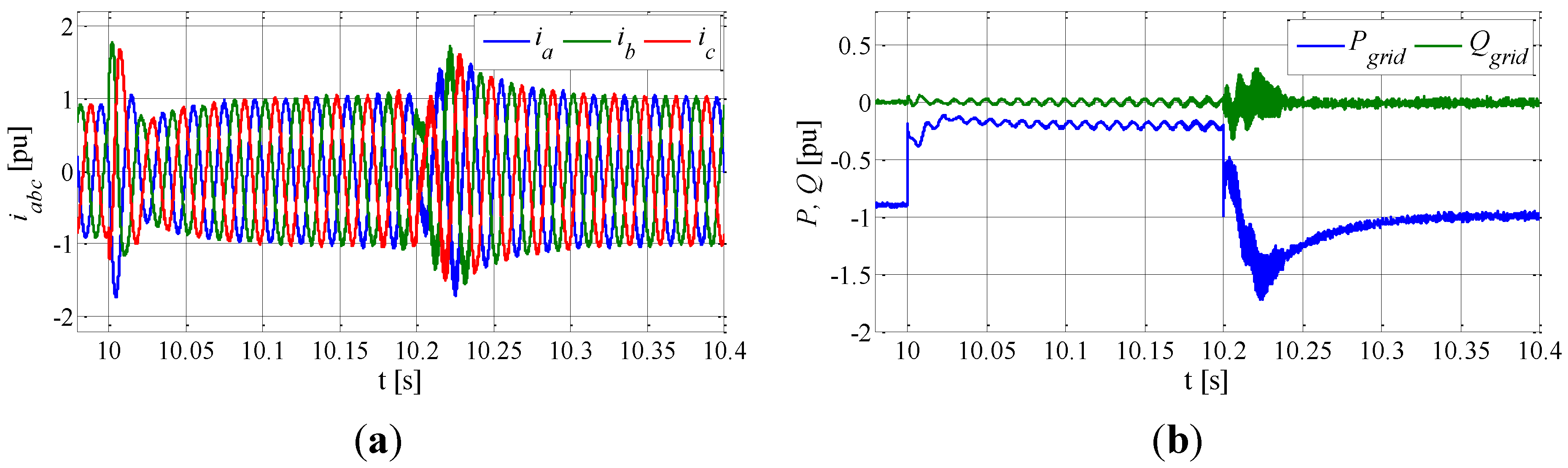
4.3. Simulation Results under Unbalanced Grid Voltage Conditions

The wind speed is set at 11 m/s. The simulation results of unbalanced grid voltage sag are presented in Figure 10. Figure 10a presents the unbalanced grid voltage. During 10.0 to 10.2 s, phase A suffers an 80% voltage sag, phase B suffers an 85% voltage sag, and phase C suffers a 75% voltage sag. As the negative current is eliminated by the controller, the high voltage side converter currents remain balanced during all the simulation time, as shown in Figure 10b, but the active and reactive power of the high voltage side converter presented in Figure 10c, suffer 2ω oscillations during the voltage sag, as a result of the negative component of the unbalanced voltage. During the unbalanced grid voltage condition, the D-PMSG controller works to extract maximum amount of power from the wind, the generator speed pitch angle and output power of D-PMSG are presented in Figure 10d–f. But the power transferred to the grid is limited by the EPT high voltage side converter current, as shown in Figure 10b. This causes the EPT low voltage side DC voltage to increase, as shown in Figure 10g during 10 to 10.1 s the DC voltage increases from 1500 to 1650 V. When the EPT low voltage side DC voltage is more than 1650 V, the supplementary controller of the DC/DC controller starts to work to absorb the redundant power to prevent the DC capacitance from over voltage, and as shown in Figure 10g the DC voltage is less than 1800 V during unbalance grid voltage conditions. The power absorbed by the super-capacitor stack is presented in Figure 10h.
Figure 10. Simulation results under unbalanced grid voltage sag conditions. (a) Unbalanced grid voltage; (b) Grid side converter current; (c) Active and reactive power transferred to the grid; (d) Generator speed; (e) Pitch angle; (f) Output power of D-PMSG; (g) EPT low voltage side DC voltage; and (h) Active power absorbed by the super-capacitor stack.
Energies 07 07330 g010aEnergies 07 07330 g010b
Another simulation of the system under unbalanced grid voltage conditions without super-capacitor is done to compare with the system with super-capacitor and the simulation results are presented in Figure 11. The unbalanced grid voltage is presented in Figure 10a. During the unbalanced grid voltage conditions, the D-PMSG controller works to extract maximum amount of power from the wind, but the power transferred to the grid, presented in Figure 11b, is limited by the EPT high voltage side converter current as shown in Figure 11a. This causes the EPT low voltage side DC voltage to increase, as shown in Figure 11c during 10 to 10.2 s the DC voltage increases from 1500 to 2750 V and may damage the super-capacitor stack. From Figure 10 and Figure 11, it can be seen that with super-capacitor the control scheme can improve the LVRT performance and prevent the DC capacitance from over voltage.
Figure 11. Simulation results under unbalanced grid voltage sag conditions without super-capacitor. (a) Grid side converter current; (b) Active and reactive power transferred to the grid; (c) Generator speed; (d) Pitch angle; (e) Output power of D-PMSG; and (f) EPT low voltage side DC voltage.
Energies 07 07330 g011aEnergies 07 07330 g011b

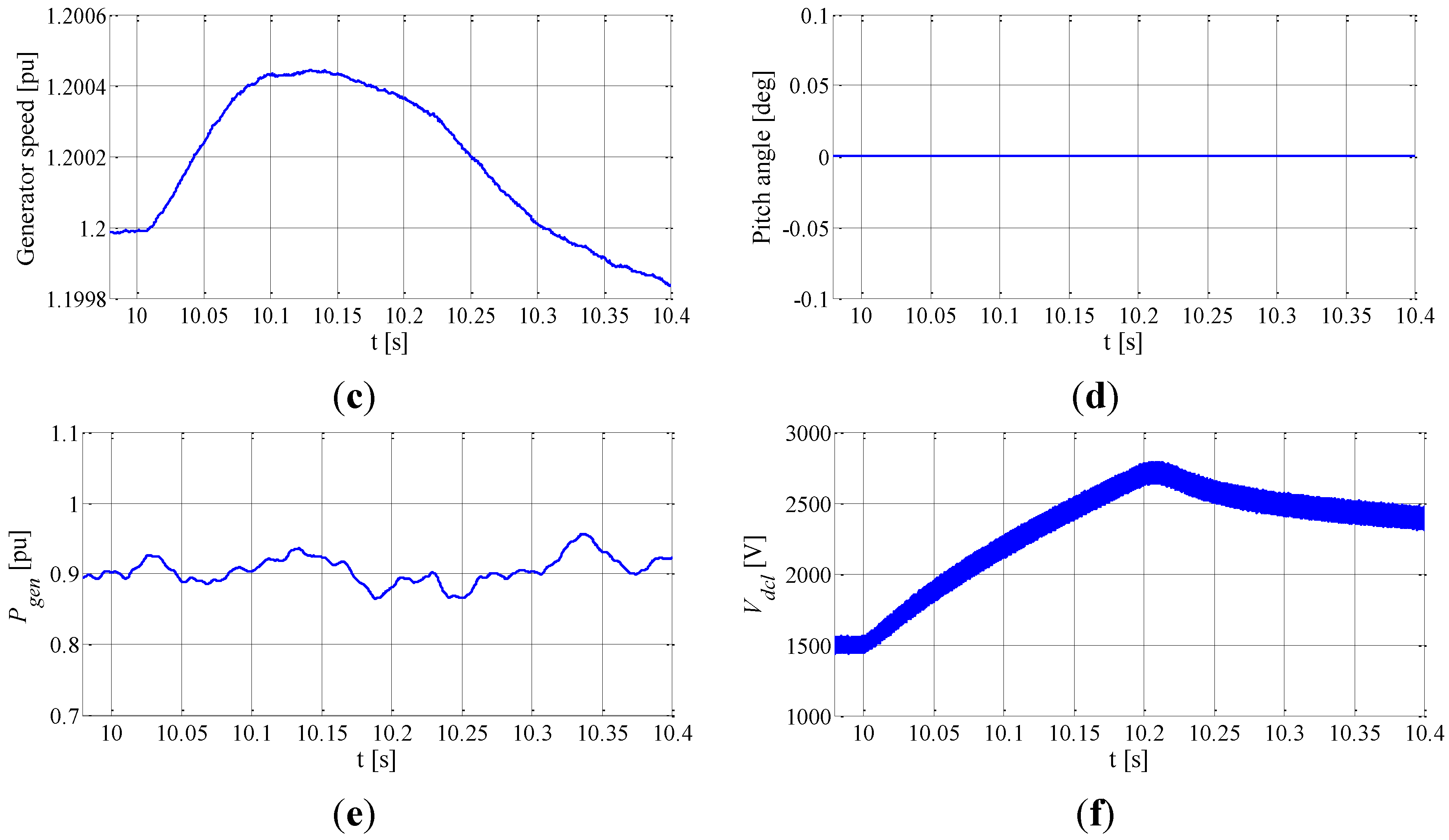
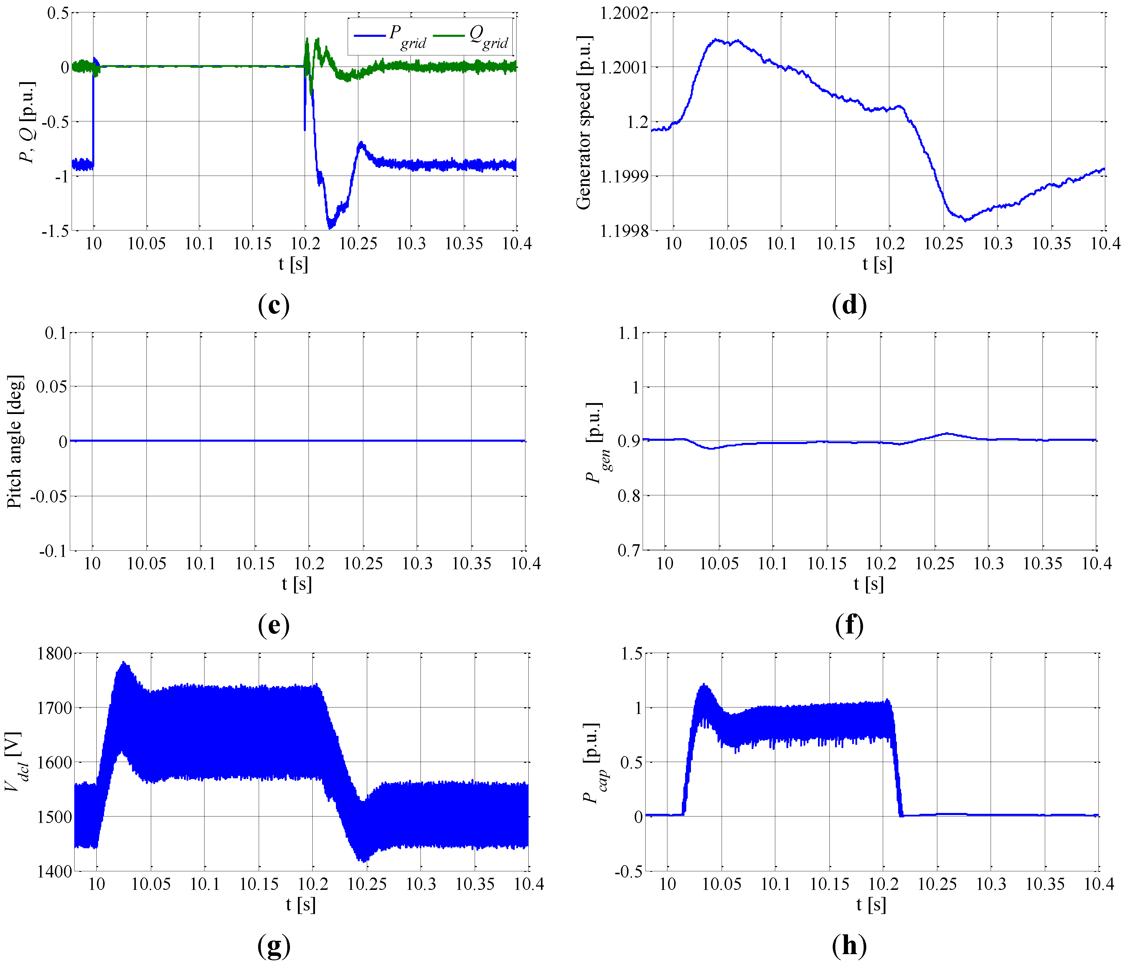
4.4. Simulation Results under Three Phase Ground Fault Conditions

The wind speed is set at 11 m/s. The three phase ground fault starts at 10.0 s and lasts for 0.2 s. The simulation results under three phase grid fault conditions are presented in Figure 12. Figure 12a presents the grid voltage. During 10.0 to 10.2 s the three phase voltages are 0 pu. The high voltage side converter currents are presented in Figure 12b. During the ground fault, as the voltage is 0 pu, the positive sequence current command i d P* and i q P* could not be calculated from Equation (8) and they are set to 0.65 and 0 pu, respectively. The active and reactive power transferred to the grid are presented in Figure 12c, which are 0 pu during the ground fault as the voltage is 0 pu. During the ground fault, the D-PMSG controller works to extract maximum amount of power from the wind which is presented in Figure 12d. However, the low voltage side DC voltage is limited to 1650 V as the redundant power is absorbed by the super-capacitor.
Figure 12. Simulation results under three phase ground fault conditions. (a) Unbalanced grid voltage; (b) Grid side converter current; (c) Active and reactive power transferred to the grid; (d) Generator speed; (e) Pitch angle; (f) Output power of D-PMSG; (g) EPT low voltage side DC voltage; and (h) Active power absorbed by the super-capacitor stack.
Energies 07 07330 g012aEnergies 07 07330 g012b

5. Conclusions

This paper has investigated how an Electronic Power Transformer incorporated with an energy storage system can be used to smooth the wind power fluctuations and enhance the LVRT capability of D-PMSGs in wind farms. The EPT system and D-PMSG system models and independent active and reactive power control strategies have been discussed The EPT control strategy for wind power fluctuation smoothing and LVRT capability enhancement of D-PMSGs has been proposed. Under normal operating conditions, the energy storage system absorbs the high frequency component of the D-PMSG output power to smooth the wind power fluctuations. Under grid fault conditions, the energy storage system absorbs the redundant power to help the D-PMSG ride through the low voltage conditions. This coordinated control strategy has been validated by simulation studies using MATLAB/Simulink, which show that the output wind power quality is improved and the D-PMSG can ride-through severe grid disturbances.

Acknowledgments

This work was supported by the Project of the National Natural Science Foundation of China (51277083) and the Exquota Study Visit Funds China-UK. (51361130151).

Author Contributions

This paper is a result of the full collaboration of all the authors. Hui Huang and Wang Dan modelled the complete system and performed simulations. Manuscript preparation was completed by Hui Huang, Chengxiong Mao, Jiming Lu and Dan Wang. All author performed results analysis and contributed to the editing and reviewing of this document.

Conflicts of Interest

The authors declare no conflict of interest.

References

  1. Carrasco, J.M.; Franquelo, L.G.; Bialasiewicz, J.T.; Galvan, E.; Guisado, R.P.; Prats, A.M.; Leon, J.I.; Moreno-Alfonso, N. Power-electronic systems for the grid integration of renewable energy sources: A survey. Ind. Electron. IEEE Trans. 2006, 53, 1002–1016. [Google Scholar]
  2. Fried, L. Global Wind Statistics 2012; Global Wind Energy Council (GWEC): Brussels, Belgium, 2013. [Google Scholar]
  3. Li, H.; Chen, Z. Overview of different wind generator systems and their comparisons. IET Renew. Power Gener. 2008, 2, 123–138. [Google Scholar] [CrossRef]
  4. Zhang, K.; Duan, Y.; Wu, J.; Qiu, J.; Lu, J.; Fan, S.; Huang, H.; Mao, C. Low voltage ride through control strategy of directly driven wind turbine with energy storage system. In Proceedings of the 2011 IEEE Power and Energy Society General Meeting, San Diego, CA, USA, 24–29 July 2011; pp. 1–7.
  5. Mi, Z.; Chen, Y.; Liu, L.; Yu, Y. Dynamic performance improvement of wind farm with doubly fed induction generators using STATCOM. In Proceedings of the 2010 International Conference on Power System Technology (POWERCON), Hangzhou, China, 24–28 October 2010; pp. 1–6.
  6. Obando-Montaño, A.F.; Carrillo, C.; Cidrás, J.; Díaz-Dorado, E. A STATCOM with supercapacitors for low-voltage ride-through in fixed-speed wind turbines. Energies 2014, 7, 5922–5952. [Google Scholar] [CrossRef] [Green Version]
  7. Han, C.; Huang, A.Q.; Baran, M.E.; Bhattacharya, S.; Litzenberger, W.; Anderson, L.; Johnson, A.L.; Edris, A.A. STATCOM impact study on the integration of a large wind farm into a weak loop power system. Energy Convers. IEEE Trans. 2008, 23, 226–233. [Google Scholar] [CrossRef]
  8. Conroy, J.F.; Watson, R. Low-voltage ride-through of a full converter wind turbine with permanent magnet generator. IET Renew. Power Gener. 2007, 1, 182–189. [Google Scholar] [CrossRef]
  9. Wang, D.; Mao, C.; Lu, J. Modelling of electronic power transformer and its application to power system. IET Gener. Transm. Distrib. 2007, 1, 887–895. [Google Scholar] [CrossRef]
  10. Manjrekar, M.D.; Kieferndorf, R.; Venkataramanan, G. Power electronic transformers for utility applications. In Proceedings of the Conference Record of the 2000 IEEE Industry Applications, Rome, Italy, 8–12 October 2000.
  11. Ronan, E.R.; Sudhoff, S.D.; Glover, S.R.; Galloway, D.L. A power electronic-based distribution transformer. Power Deliv. IEEE Trans. 2002, 17, 537–543. [Google Scholar]
  12. Van der Merwe, J.W. The solid-state transformer concept: A new era in power distribution. In Proceedings of the 2009 AFRICON, Nairobi, Kenya, 23–25 September 2009.
  13. Wang, D.; Mao, C.; Lu, J.; Liu, H. Auto-balancing transformer based on power electronics. Electr. Power Syst. Res. 2010, 80, 28–36. [Google Scholar] [CrossRef]
  14. Wang, D.; Mao, C.; Lu, J.; Fan, S.; Peng, F. Theory and application of distribution electronic power transformer. Electr. Power Syst. Res. 2007, 77, 219–226. [Google Scholar] [CrossRef]
  15. Sang, Z.; Mao, C.; Lu, J.; Wang, D. Analysis and simulation of fault characteristics of power switch failures in distribution electronic power transformers. Energies 2013, 6, 4246–4268. [Google Scholar] [CrossRef]
  16. Liu, H.; Mao, C.; Lu, J.; Wang, D. Electronic power transformer with supercapacitors storage energy system. Electr. Power Syst. Res. 2009, 79, 1200–1208. [Google Scholar] [CrossRef]
  17. Liu, H.; Mao, C.; Lu, J.; Wang, D. Optimal regulator-based control of electronic power transformer for distribution systems. Electr. Power Syst. Res. 2009, 79, 863–870. [Google Scholar] [CrossRef]
  18. Brando, G.; Dannier, A.; Rizzo, R. Power electronic transformer application to grid connected photovoltaic systems. In Proceedings of the 2009 International Conference on Clean Electrical Power, Capri, Italy, 9–11 June 2009.
  19. Gupta, R.K.; Castelino, G.F.; Mohapatra, K.K.; Mohan, N. A novel integrated three-phase, switched multi-winding power electronic transformer converter for wind power generation system. In Proceedings of the 35th Annual Conference of IEEE Industrial Electronics 2009, Porto, Portugal, 3–5 November 2009.
  20. She, X.; Huang, A.Q.; Wang, F.; Burgos, R. Wind energy system with integrated functions of active power transfer, reactive power compensation, and voltage conversion. Ind. Electron. IEEE Trans. 2013, 60, 4512–4524. [Google Scholar] [CrossRef]
  21. Zhang, M.; Chen, J.; Wang, Z.; Wang, S.; Ouyang, L. A new permanent magnet synchronous wind-power generation grid-connected system. Power Syst. Prot. Control 2013, 41, 141–148. [Google Scholar]
  22. Zhang, M.; Liu, J.; Jin, X. Research on the SVPWM solid state transformer applied in smart micro-grid. Trans China Electrotech. Soc. 2012, 27, 90–97. (In Chinese) [Google Scholar]
  23. She, X.; Huang, A.Q.; Lukic, S.; Baran, M.E. On integration of solid-state transformer with zonal DC microgrid. Smart Grid IEEE Trans. 2012, 3, 975–985. [Google Scholar] [CrossRef]
  24. Muyeen, S.M.; Ali, M.H.; Takahashi, R.; Murata, T.; Tamura, J.; Tomaki, Y.; Sakahara, A.; Sasano, E. Comparative study on transient stability analysis of wind turbine generator system using different drive train models. Renew. Power Gener. IET 2007, 1, 131–141. [Google Scholar] [CrossRef]
  25. De Doncker, R.W.A.A.; Divan, D.M.; Kheraluwala, M.H. A three-phase soft-switched high-power-density DC/DC converter for high-power applications. Ind. Appl. IEEE Trans. 1991, 27, 63–73. [Google Scholar]
  26. Song, H.; Nam, K. Dual current control scheme for PWM converter under unbalanced input voltage conditions. Ind. Electron. IEEE Trans. 1999, 46, 953–959. [Google Scholar] [CrossRef]
  27. Chinchilla, M.; Arnaltes, S.; Burgos, J.C. Control of permanent-magnet generators applied to variable-speed wind-energy systems connected to the grid. Energy Convers. IEEE Trans. 2006, 21, 130–135. [Google Scholar] [CrossRef]
  28. Miller, N.W.; Price, W.W.; Sanchez-Gasca, J.J. GE-Power Systems Energy Consulting: Dynamic Modeling of GE 1.5 and 3.6 Wind Turbine-Generators; General Electric International, Inc.: Schenectady, NY, USA, 2003. [Google Scholar]
  29. Clark, K.; Miller, N.W.; Sanchez-Gasca, J.J. General Electric International Technical Report: Modeling of GE Wind Turbine-Generators for Grid Studies; General Electric International, Inc.: Schenectady, NY, USA, 2010. [Google Scholar]
  30. Enjeti, P.N.; Choudhury, S.A. A new control strategy to improve the performance of a PWM AC to DC converter under unbalanced operating conditions. Power Electron. IEEE Trans. 1993, 8, 493–500. [Google Scholar] [CrossRef]

