1. Introduction
Double Rotor Machine (DRM) is an electro-mechanical energy converter based on the traditional single rotor machine by increasing the number of rotors. There are two mechanical ports and two electrical ports, which allow the energy transformed between these four ports bidirectionally. When applied in Hybrid Electrical Vehicle (HEV), the DRM can achieve different functionalities such as motoring, generating, as well as continuous variable transmission. The electrical and mechanical energy can be adjusted accordingly to achieve high efficiency and dynamic performance. The clutches, gear transmission and alternator can be replaced by the DSM, which is a novel vehicle transmission system [
1,
2,
3].
At present, researches of induction machine (IM) [
4] and permanent magnet (PM) [
5] based on DRM have been very common. Many researchers are working to solve the problems of field coupling control strategy [
6], cooling of the inner rotor [
7], manufacture and totally brushless configurations [
8]. They set a foundation for practical application. However, there are a lot of problems to be further studied.
Some scholars have started to study the switched reluctance based on DRM (SRDRM) [
9]. Both theoretical analysis and experimental results show that SRDRM not only has the same advantages as PMDRM but also can be operated in different modes flexibly, which makes SRDRM an interesting candidate for HEVs [
10].
By employing switched reluctance machine, SRDRM can be established, which inherits the merits of switched reluctance machine [
11]: (1) Simple structure without conductors or PMs on the rotor; (2) concentrated windings with short end on the stator without phase jumper wire, which offers high reliability; (3) wide constant power speed range, which is suitable for traction application.
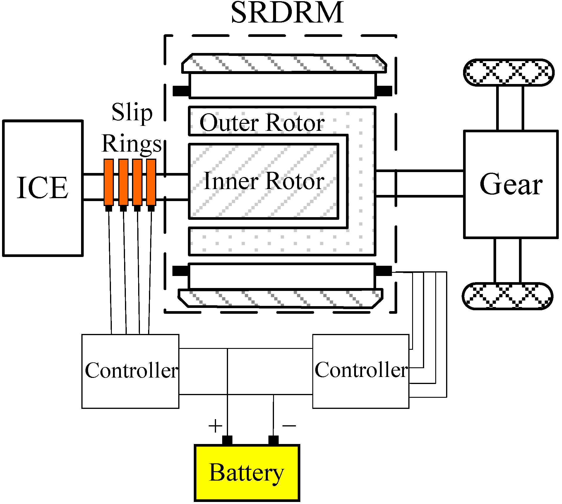
The scheme of SRDRM drivetrain in a hybrid system is shown in
Figure 1. It offers flexible speed and torque transmission, which allows the engine to operate in the efficient optimized region under different working conditions. Thus, fuel economy and emission performances can be significantly improved.
Figure 1.
SRDRM in hybrid electric vehicle system.
Figure 1.
SRDRM in hybrid electric vehicle system.
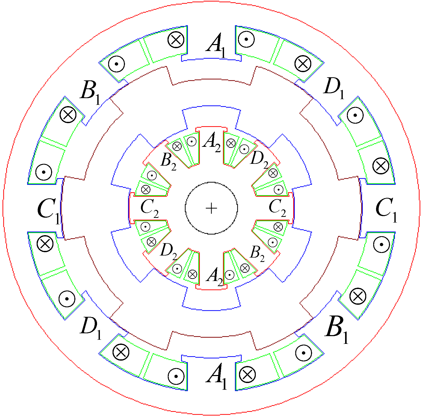
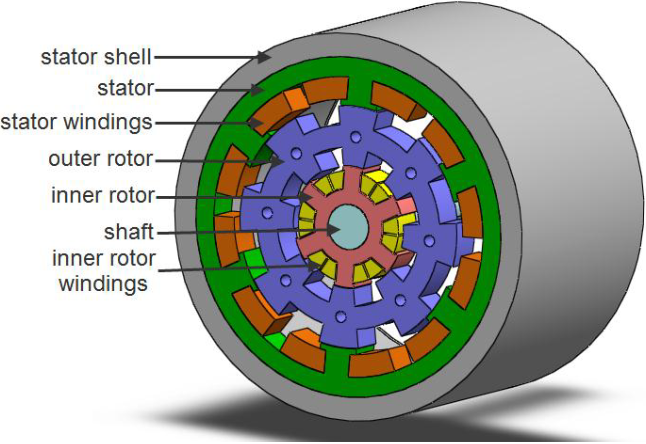
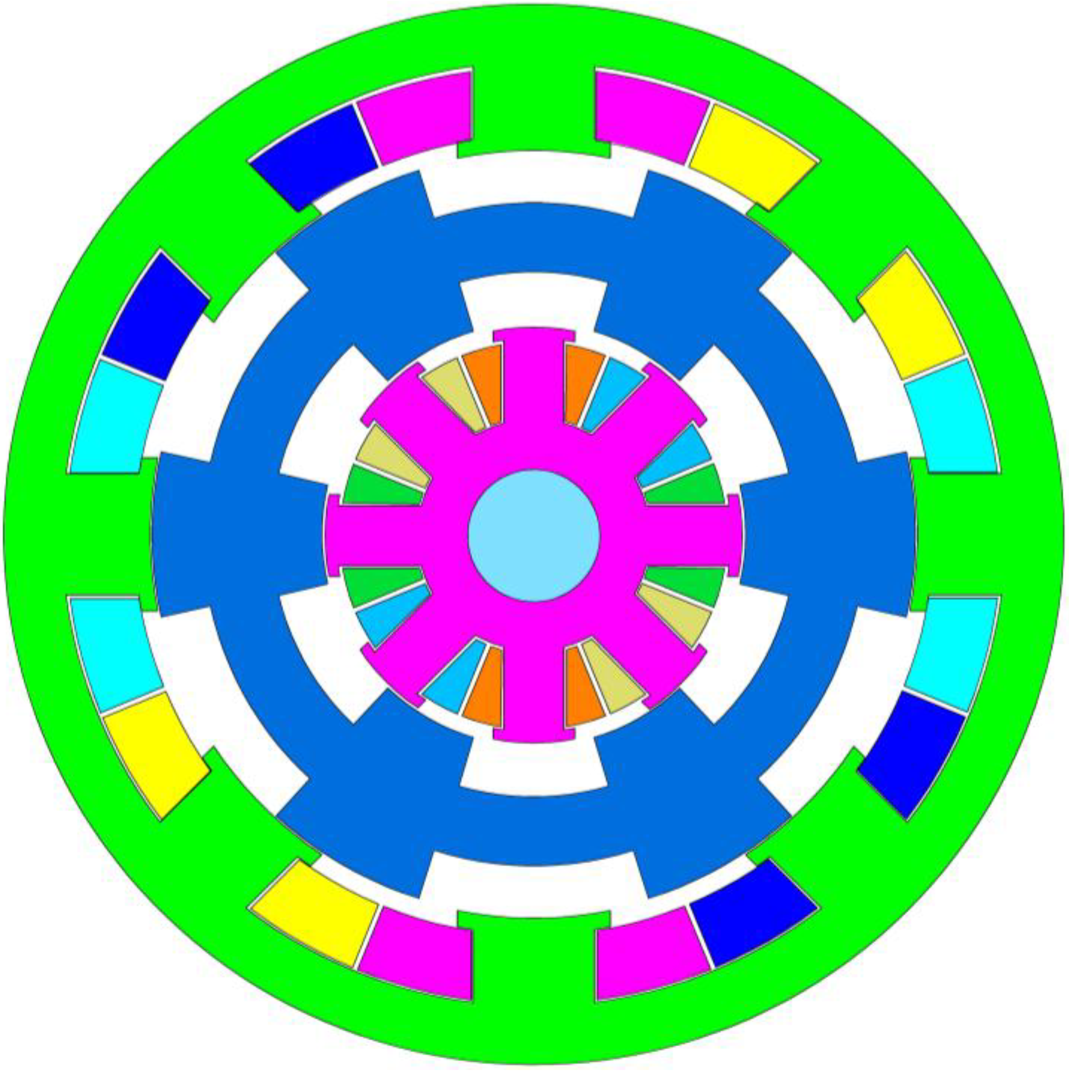
In this paper, a kind of SRDRM is proposed for hybrid electric vehicles. It integrates two switched reluctance machines,
i.e., an outer motor which consists of the stator and the outer rotor and an inner motor which consists of the outer rotor and the inner rotor, with two independent mechanical output shafts. The armature windings are located in the stator and inner rotor, and there are no conductors or PMs in the outer rotor, showing in
Figure 2. Compared to other DRMs, SRDRM not only has the advantage of rigid rotor structure, high reliability and wide speed range, but also gets rid of the cooling problem of the outer rotor. As shown in the
Figure 2, the SRDRM is composed of two switched reluctance machines which share one solid rotor. Both the stator and inner rotor windings are connected to batteries through DC/AC inverters respectively.
Figure 2.
Structure of SRDRM.
Figure 2.
Structure of SRDRM.
By using an equivalent magnetic circuit model, the function of the outer rotor yoke is analyzed. Electromagnetic analyses of the SRDRM are performed with analytical calculations and 2-D finite element methods, including the effects of main parameters on performance. Finally, a 4.4 kW prototype machine is designed and manufactured, and the experimental tests are done to validate the proposed design.
2. Magnetic Equivalent Circuit Analysis of SRDRM
Based upon equivalent magnetic flux principle, the magnetic model can be established. The magnetic circuit model describes the magneto-motive force (MMF), flux and flux paths in the machine as different components in an electrical circuit [
12], in which the detailed analysis of the magnetic distribution is not necessary. The equivalent magnetic circuit model follows the magnetic Ohm’s law and magnetic Kirchhoff’s law, and the following relationship is established:
where,
Ui is the magnetic voltage drop;
Ri is the magnetic reluctance; Φ
i is the magnetic flux flow;
Fi is the MMF of the branch;
n is the node number of the magnetic model;
m is the branch number of each node.
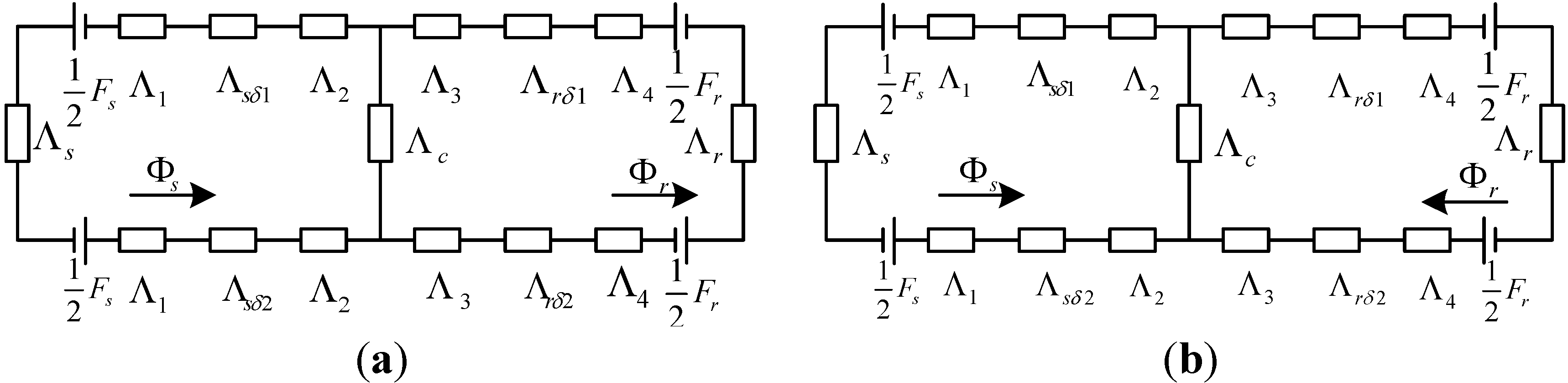
In order to establish the SRDRM equivalent model, the edge effects and magnetic flux non-linearity are neglected and the magnetic steel permeability is considered to be infinity
μ = ∞. When the stator and inner rotor are energized at the same time, the equivalent magnetic circuit models of SRDRM are shown in
Figure 3.
Figure 3.
Equivalent magnetic circuits of SRDRM: (a) MMF directions of stator and rotor windings are the same; (b) MMF directions of stator and rotor windings are opposite.
Figure 3.
Equivalent magnetic circuits of SRDRM: (a) MMF directions of stator and rotor windings are the same; (b) MMF directions of stator and rotor windings are opposite.
Where Fs, Fr are the stator and inner rotor MMF established by the excited armature windings respectively; Λs, Λc and Λr are the permeances of stator yoke, outer rotor yoke and inner rotor yoke respectively; Λsδ1 and Λsδ2 are the air gap permeances under stator poles; Λrδ1 and Λrδ2 are the air gap permeances under inner rotor poles; Λ1, Λ2, Λ3 and Λ4 are the permeances of stator tooth, outer rotor’s outer tooth, outer rotor’s inner tooth and inner rotor tooth respectively.
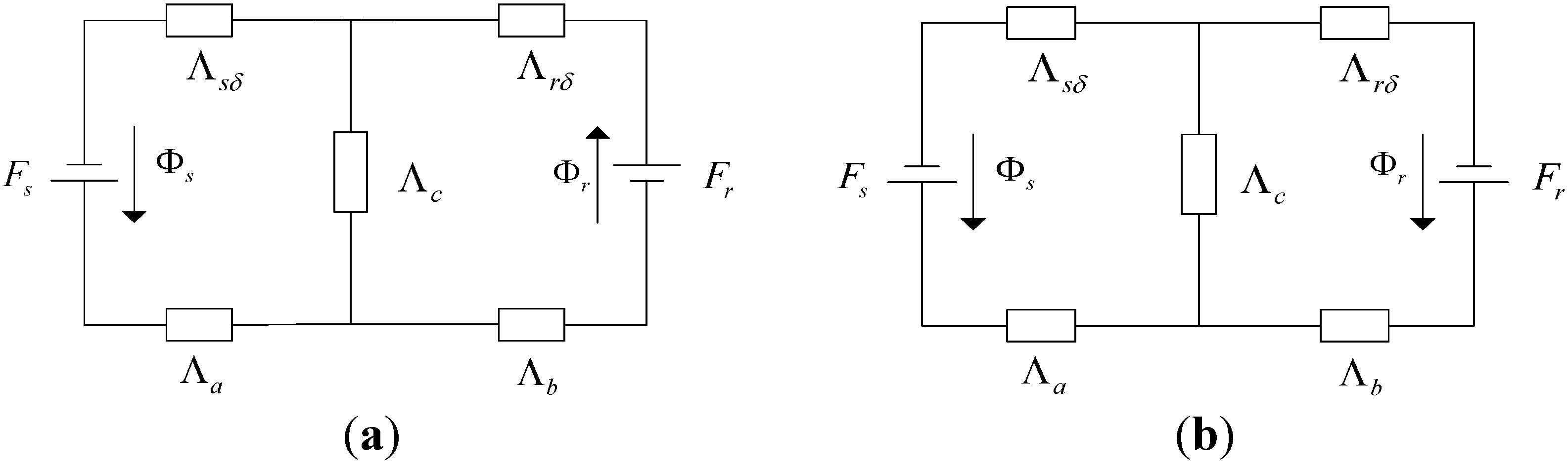
When the current is low, the permeances of stator, outer rotor, and inner rotor are all constants, while the double salient structure changes the gap permeance with the variations of outer rotor’s position angle, namely:
The magnetic circuit in
Figure 3 can be simplified as
Figure 4:
Figure 4.
Simplified equivalent magnetic circuits diagrams of SRDRM: (a) MMF directions of stator and rotor windings are the same; (b) MMF directions of stator and rotor windings are opposite.
Figure 4.
Simplified equivalent magnetic circuits diagrams of SRDRM: (a) MMF directions of stator and rotor windings are the same; (b) MMF directions of stator and rotor windings are opposite.
Apply the Kirchhoff’s loop law on
Figure 4a, the mathematical equations are obtained:
Solving the equations:
where,
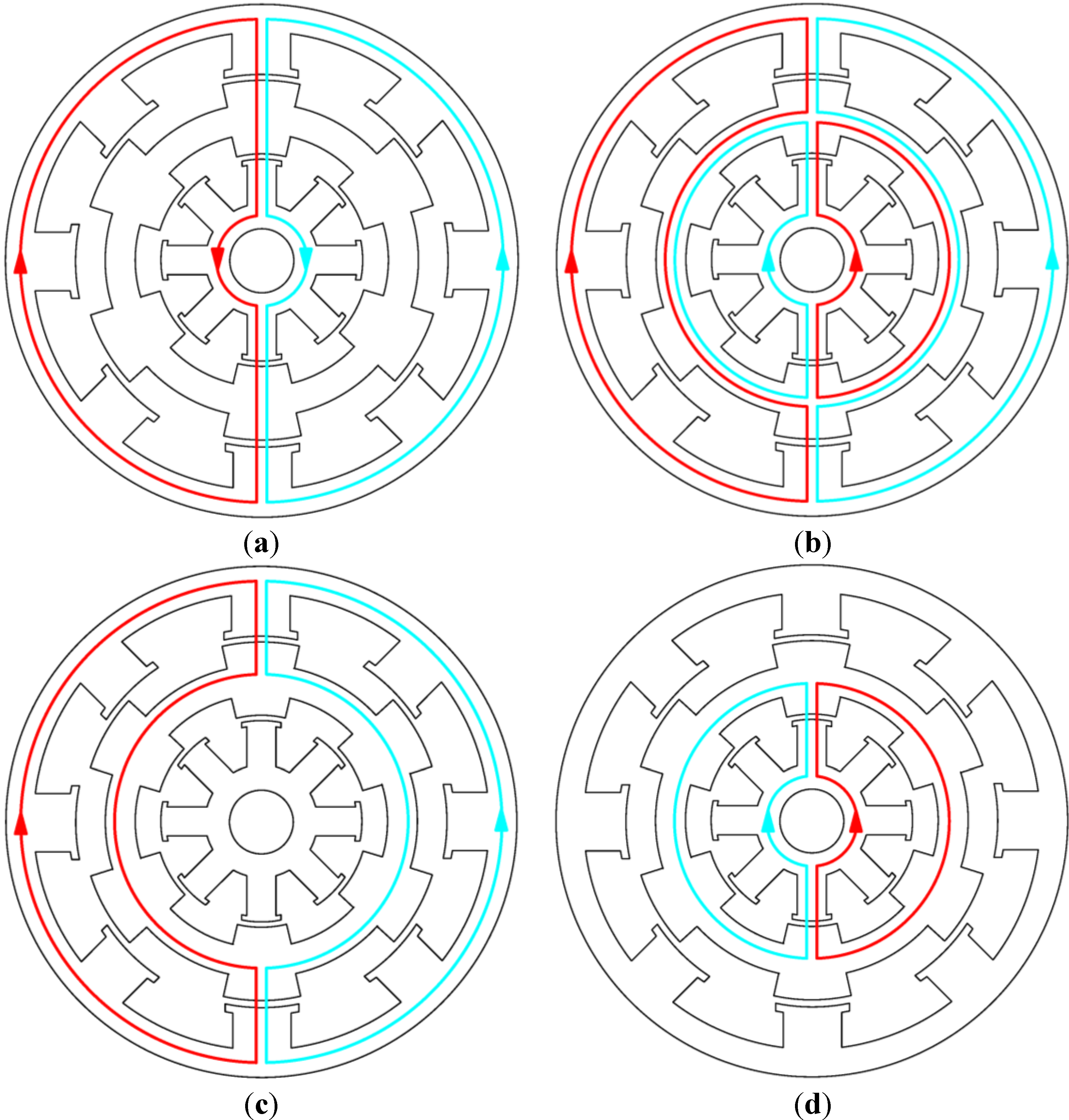
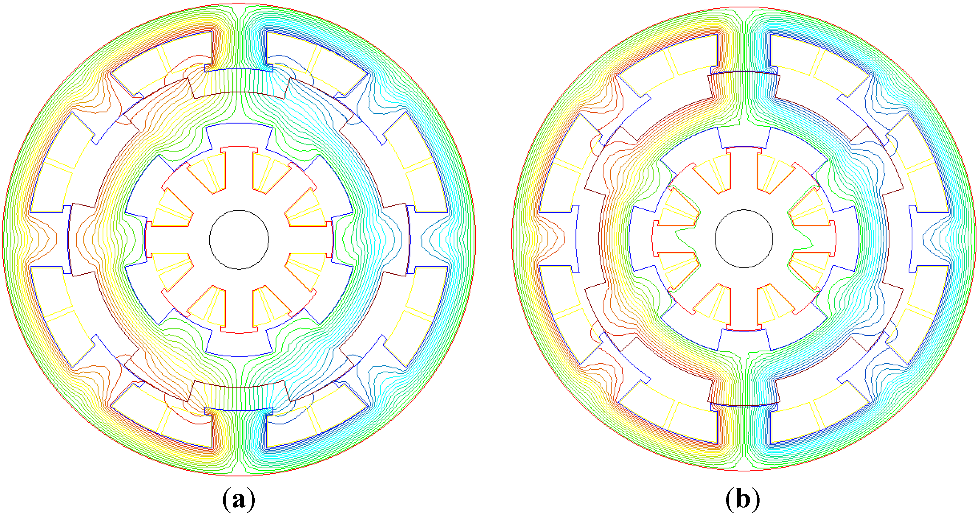
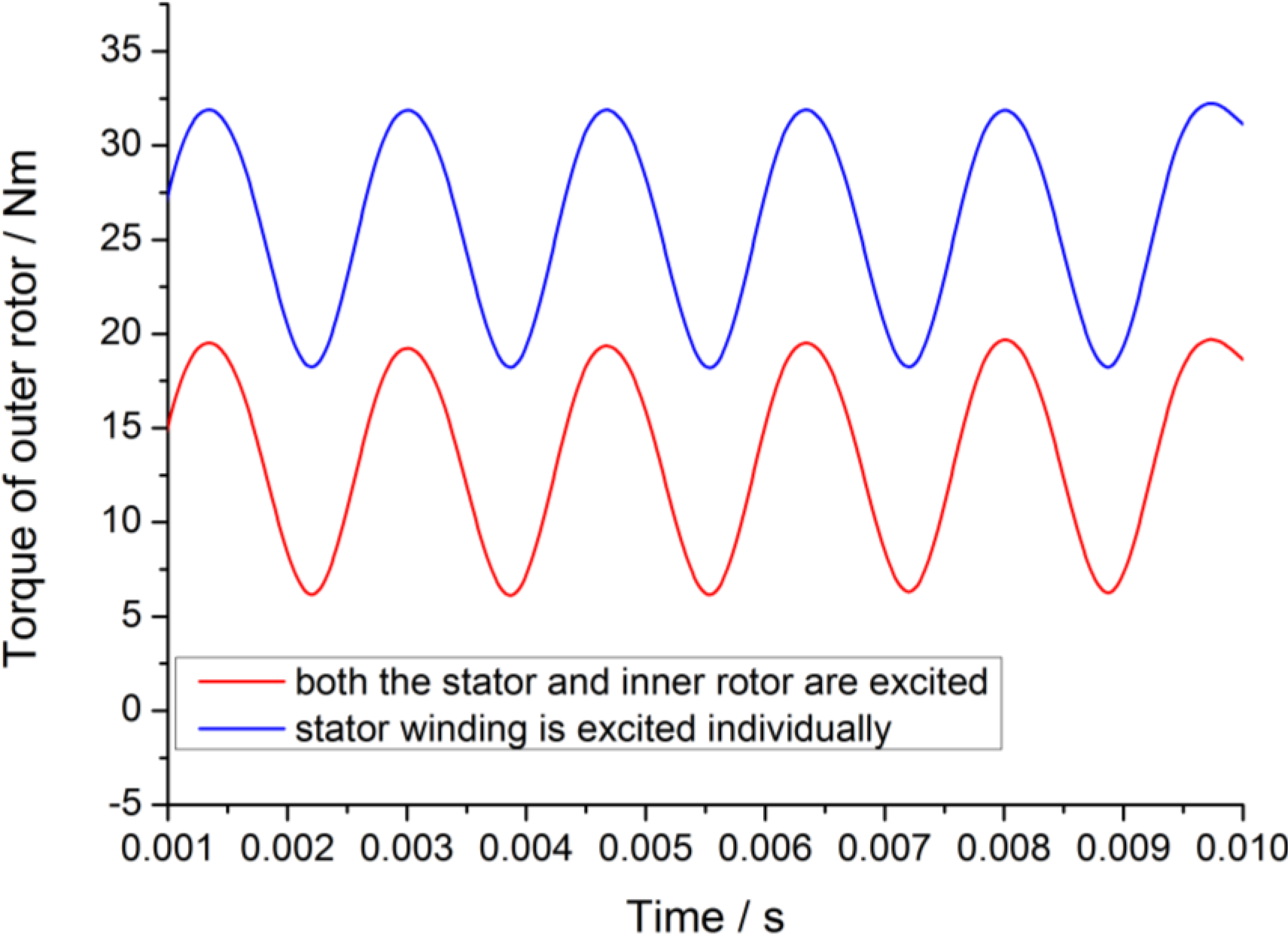
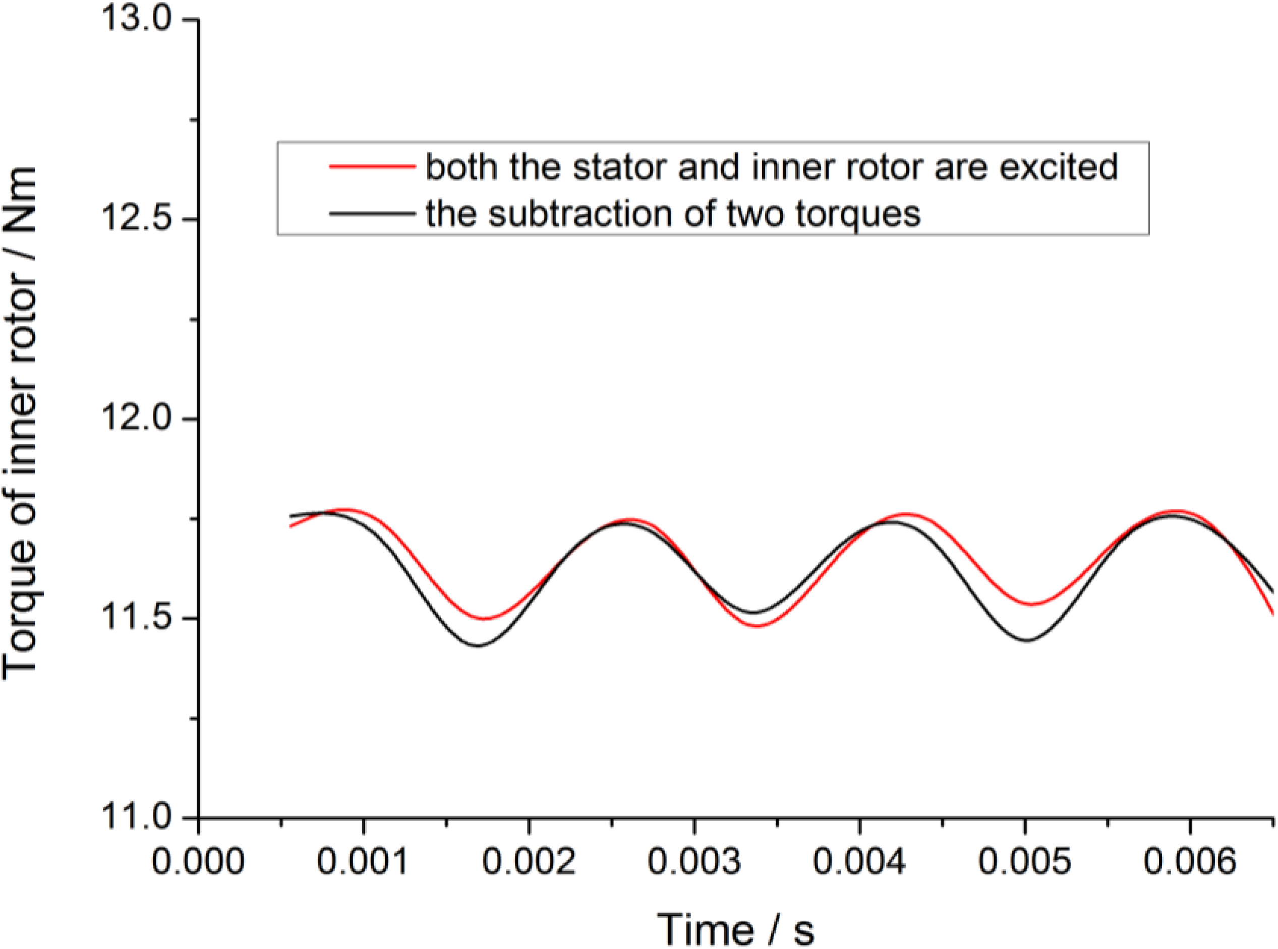
From the equations above, the magnetic flux of stator and inner rotor is related to both excitations of the stator and the inner rotor. When the stator and rotor excitations satisfy certain relationship, Φ
s = Φ
r, there is no magnetic line of force in the outer rotor’s yoke, as can be seen in
Figure 5a. Therefore, the outer rotor’s yoke can be designed very thin. When the excitation works in the opposite directions, both flux lines from stator and inner rotor travel in the outer rotor yoke, as shown in
Figure 5b. In this case, the outer rotor’s yoke has to be designed very thick; otherwise it will be highly saturated. And the output torque will be affected significantly. When the stator winding is energized alone, the majority of the magnetic flux lines travel through the outer rotor yoke, because the outer rotor’s yoke reluctance
Rc is much smaller than
R2. The magnetic flux enters into the inner rotor core only when the outer rotor’s yoke is highly saturated, as shown in
Figure 5c.
Figure 5d shows the magnetic flux line distribution when the inner rotor winding is energized alone. Four cases may occur when SRDRM runs, so the outer rotor’s yoke should be sized for the heaviest magnetic condition.
When the machine geometry parameters are determined, Rc in Equation (6) is fixed, and R1 and R2 are two groups of magnetization curves of the outer rotor angular position. The phase current and magnetic energy storage can be obtained by calculating the flux linkage and its variation, such that the transient electromagnetic torque can be derived.
From the analysis above, it can also be seen that the outer rotor’s magnetic yoke is very important in the electromagnetic design of SRDRM. Small Rc results in small electromagnetic interference between the inner and outer motor. Increasing the thickness of the outer rotor can reduce Rc, however, a thicker outer rotor leads to a bigger diameter of stator, which will significantly increase the size and weight of the machine.
Figure 5.
Different magnetic circuits of SRDRM: (a) Magnetic circuit in series; (b) Magnetic circuit in parallel; (c) Stator winding works alone; (d) Inner rotor winding works alone.
Figure 5.
Different magnetic circuits of SRDRM: (a) Magnetic circuit in series; (b) Magnetic circuit in parallel; (c) Stator winding works alone; (d) Inner rotor winding works alone.
3. Finite Element Analysis of SRDRM
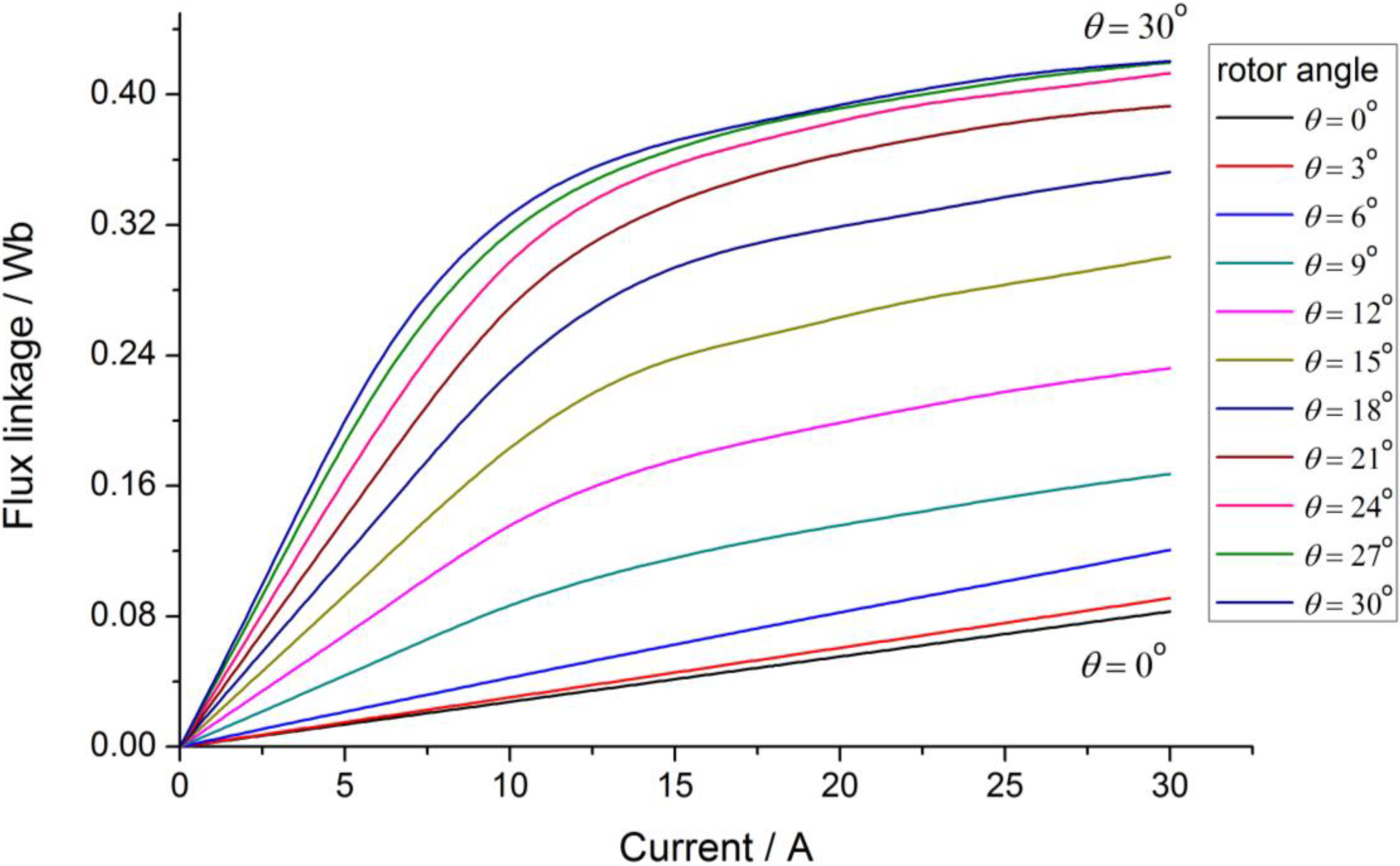
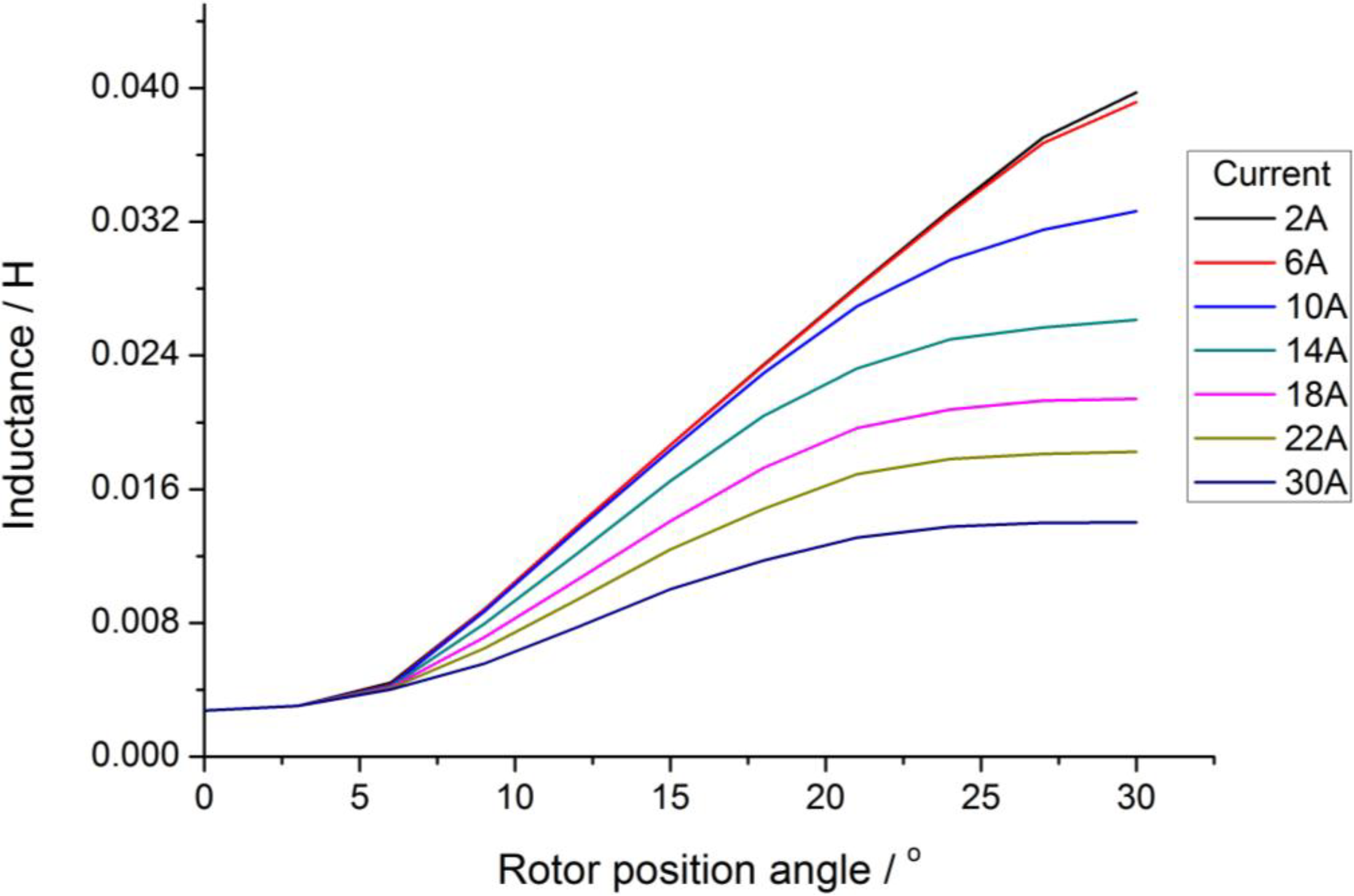
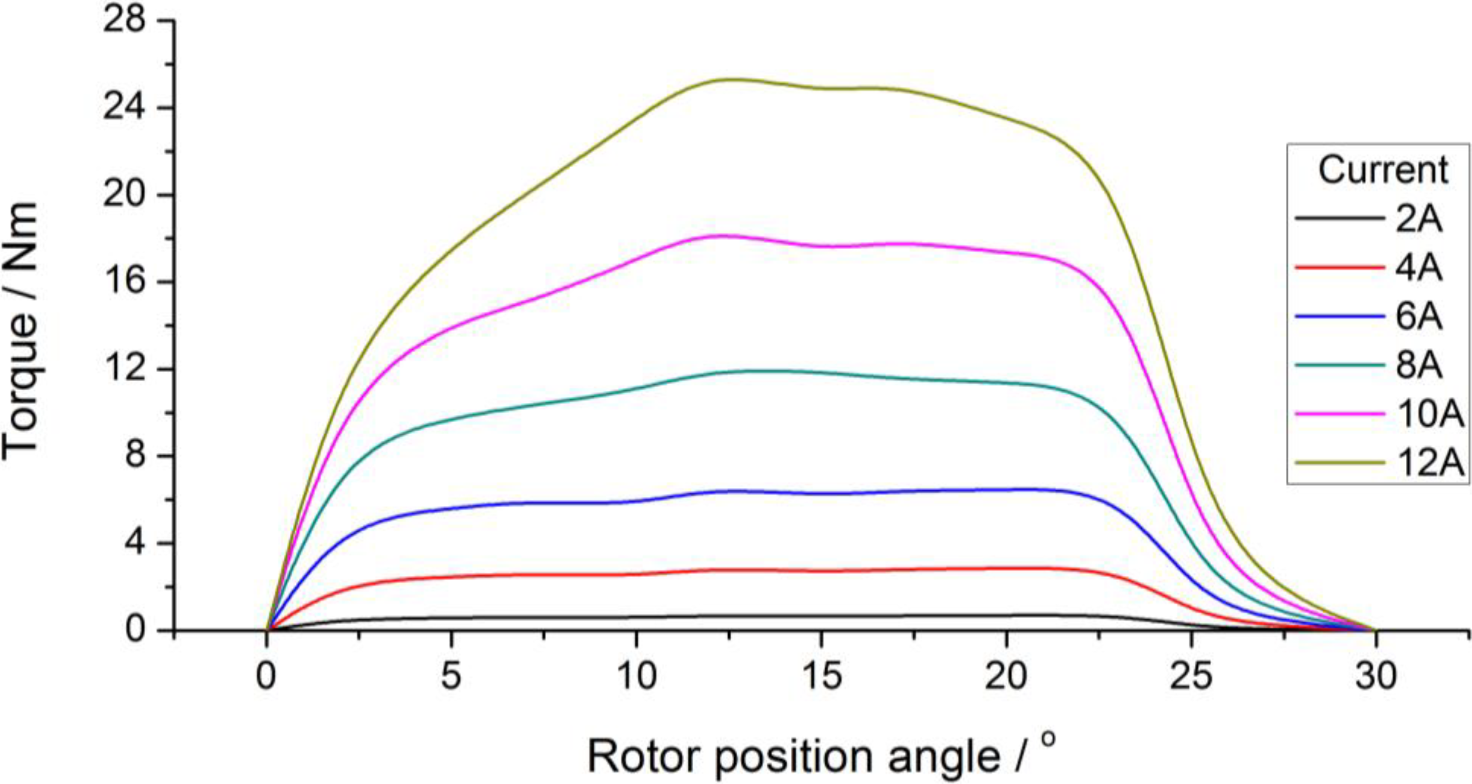
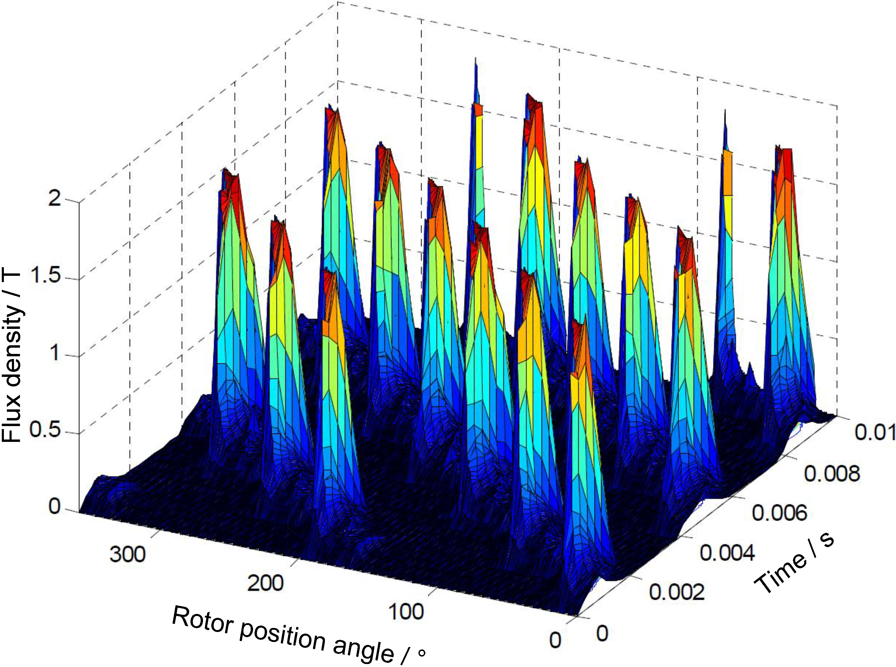
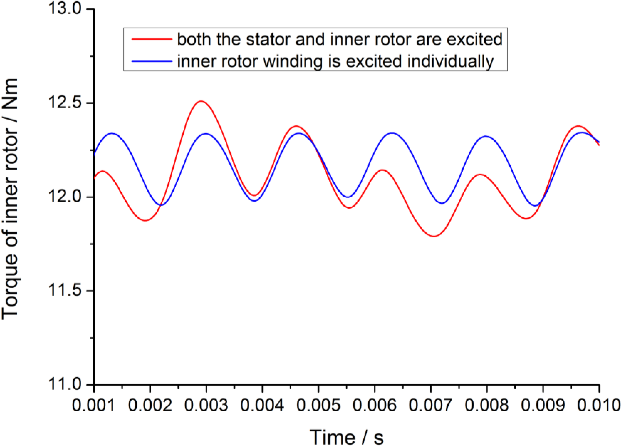
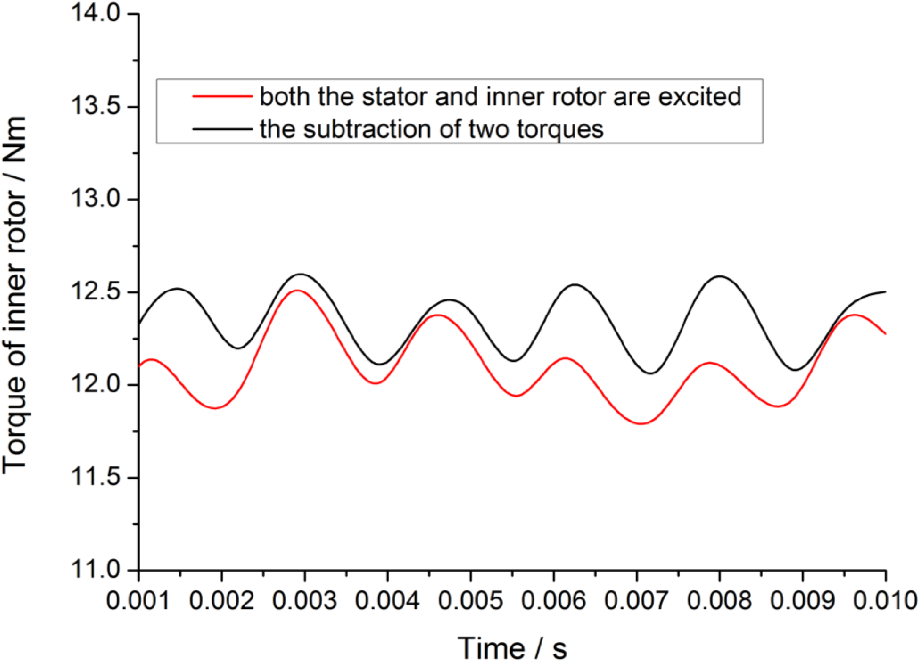
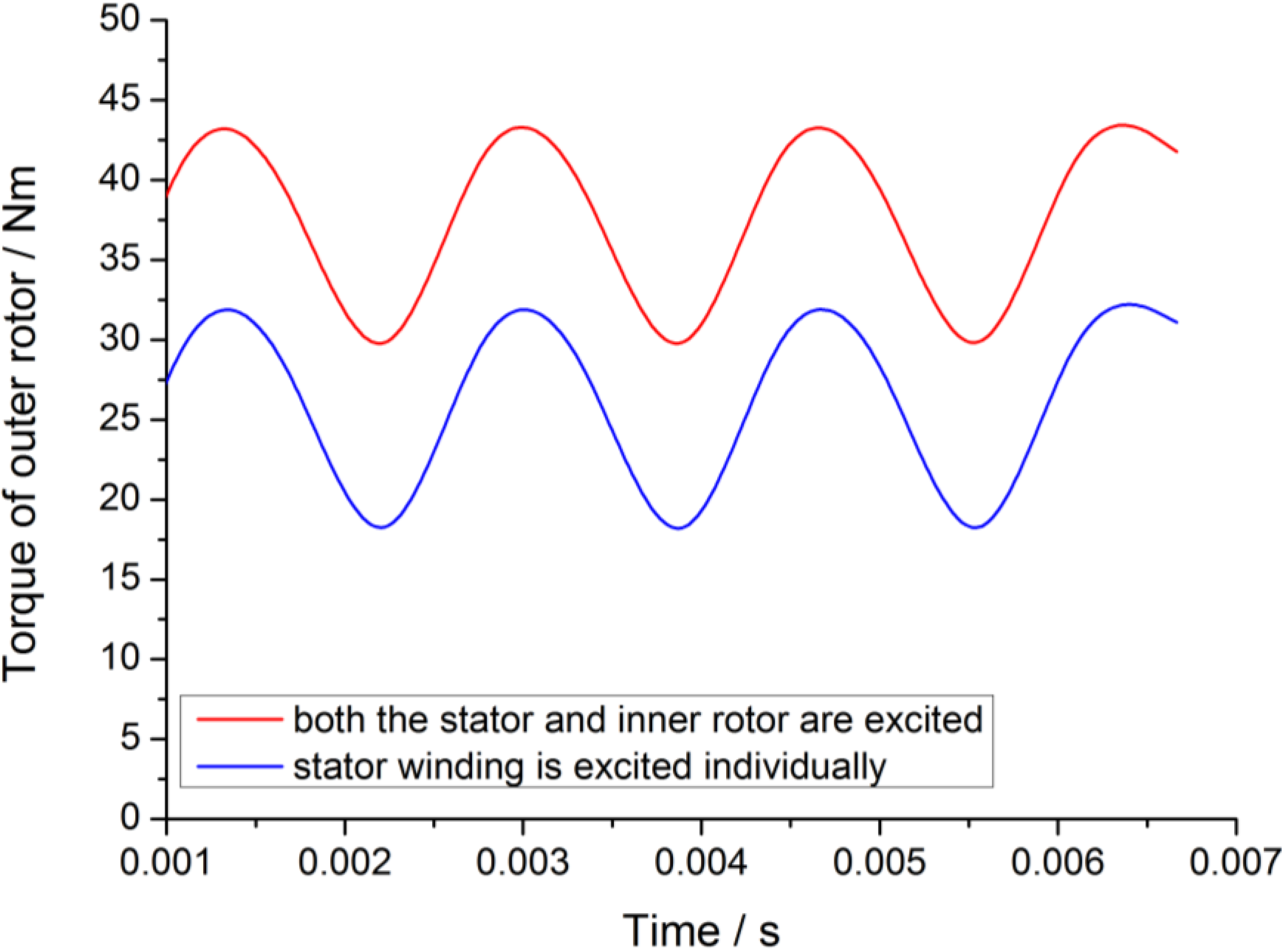
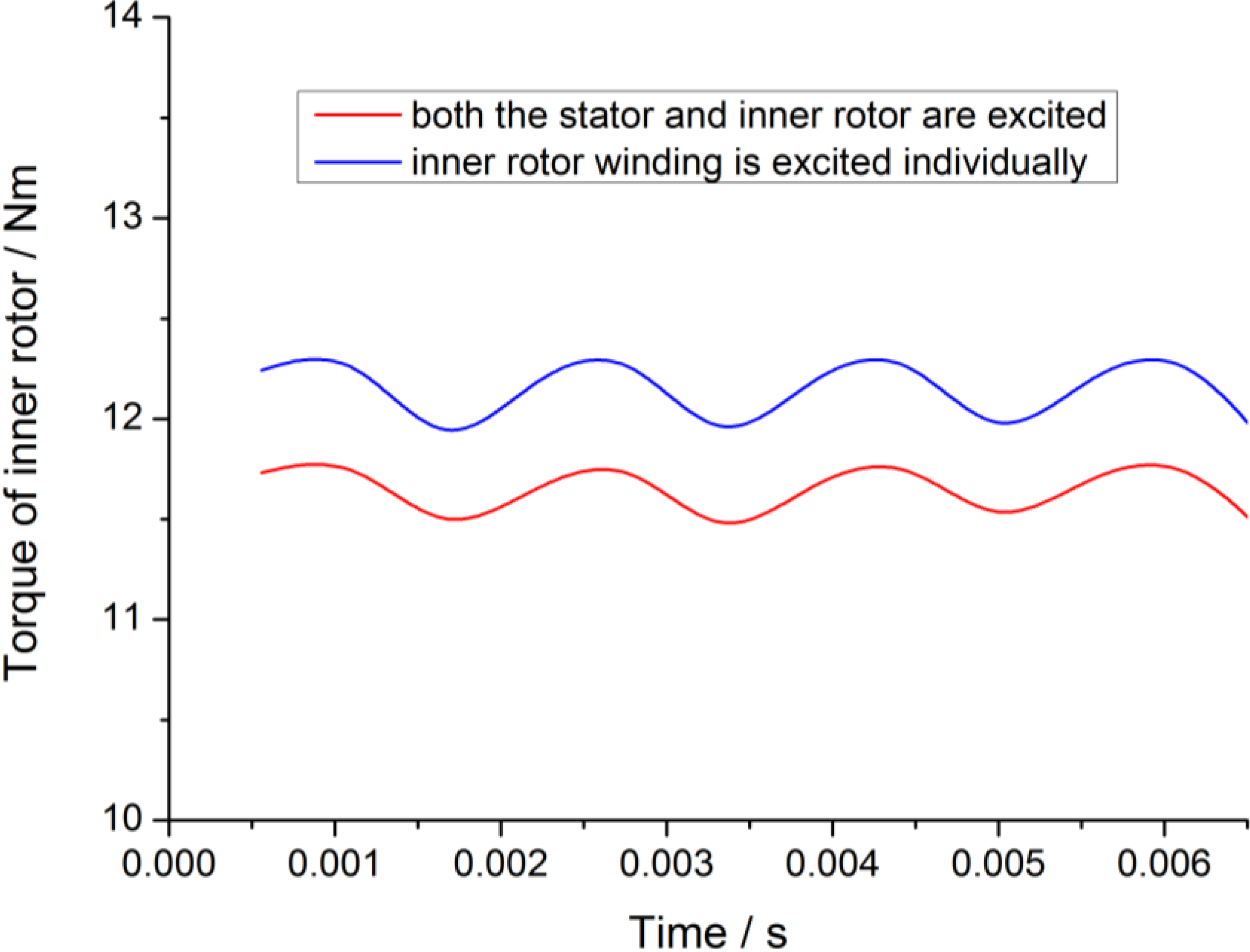
Due to the high saturation of the motor, magnetizing characteristics (Ψ-i) of SRM have to be calculated under different excitations and different rotor positions. Finite element analysis (FEA), one of the most effective tools for electromagnetic analysis, is utilized in this paper by Maxwell 2D software. The transient performance of each motor in the SRDRM is analyzed individually by injecting current to one of the motor windings. Effects of magnetic coupling between these two motors on the SRDRM performance are simulated under static state.
In order to simplify the design and FEA, performance indexes of inner motor and outer motor are the same, including voltage, rated speed and rated power. The internal and external armature winding are fed by two controllers independently. The key design data are listed in
Table 1.
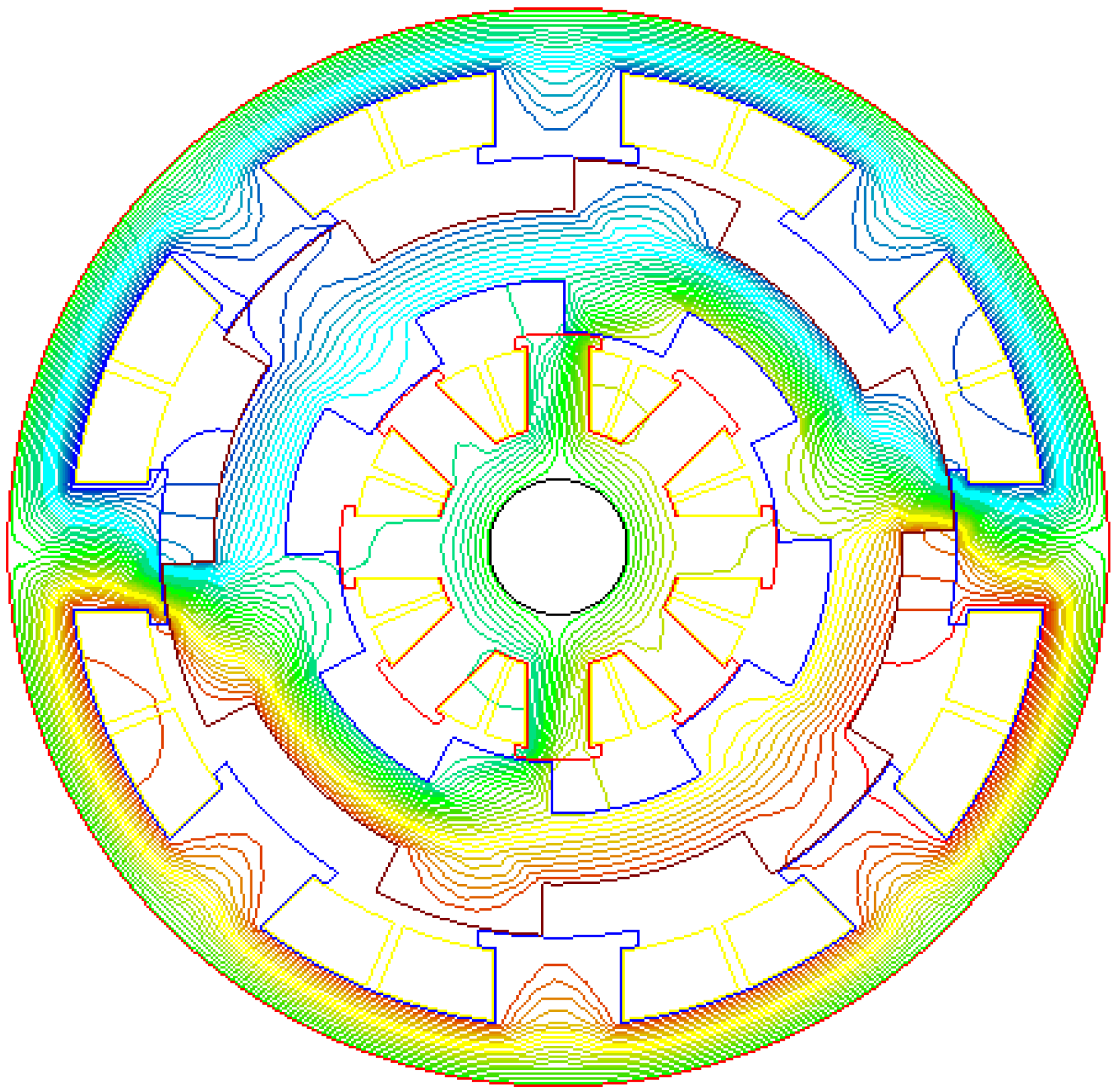
Figure 6 shows the 2D FEA model of SRDRM.
Table 1.
Main parameters of the SRDRM.
Table 1.
Main parameters of the SRDRM.
| Parameters | Outer Motor | Inner Motor |
|---|
| Rated RMS Voltage (V) | 380 | 380 |
| Rated Power (kW) | 2.2 | 2.2 |
| Maximum Power (kW) | 4.4 | 2.2 |
| Number of Phases | 4 | 4 |
| Number of poles | 8/6 | 8/6 |
| Rated Speed (rpm) | 1500 | 1500 |
| Maximum Speed (rpm) | 3000 | 3000 |
| Air Gap (mm) | 0.4 | 0.4 |
| Outer Diameter of Stator (mm) | 200 | - |
| Outer Diameter of Outer Rotor (mm) | 144 | - |
| Outer Diameter of Inner Rotor (mm) | - | 79.2 |
| Diameter of Shaft (mm) | - | 20 |
| Stator/Inner Rotor Pole Arc (°) | 23 | 23 |
| Outer Rotor Pole Arc (°) | 27 | 27 |
| Length of Core (mm) | 130 | 130 |
| Number of Turns for one phase | 84 | 74 |
Figure 6.
2D FEA model of SRDRM.
Figure 6.
2D FEA model of SRDRM.
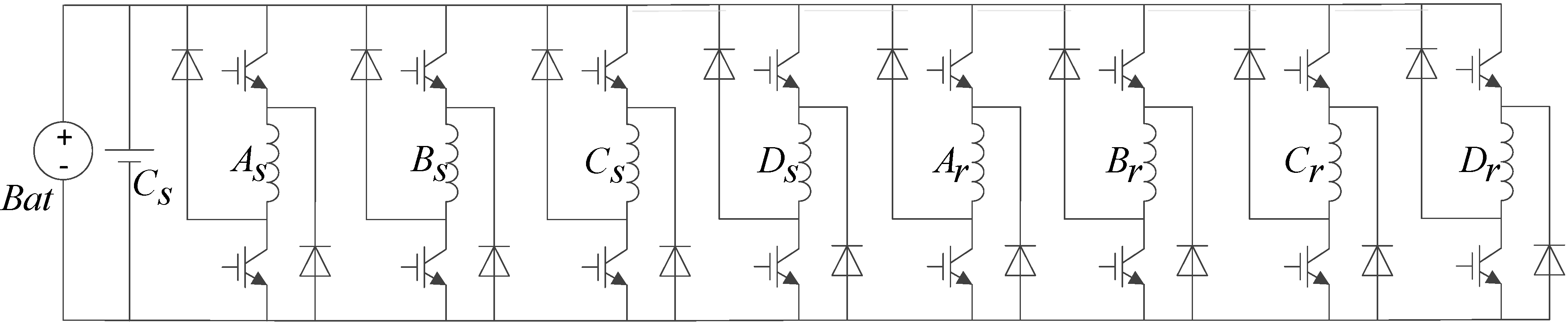
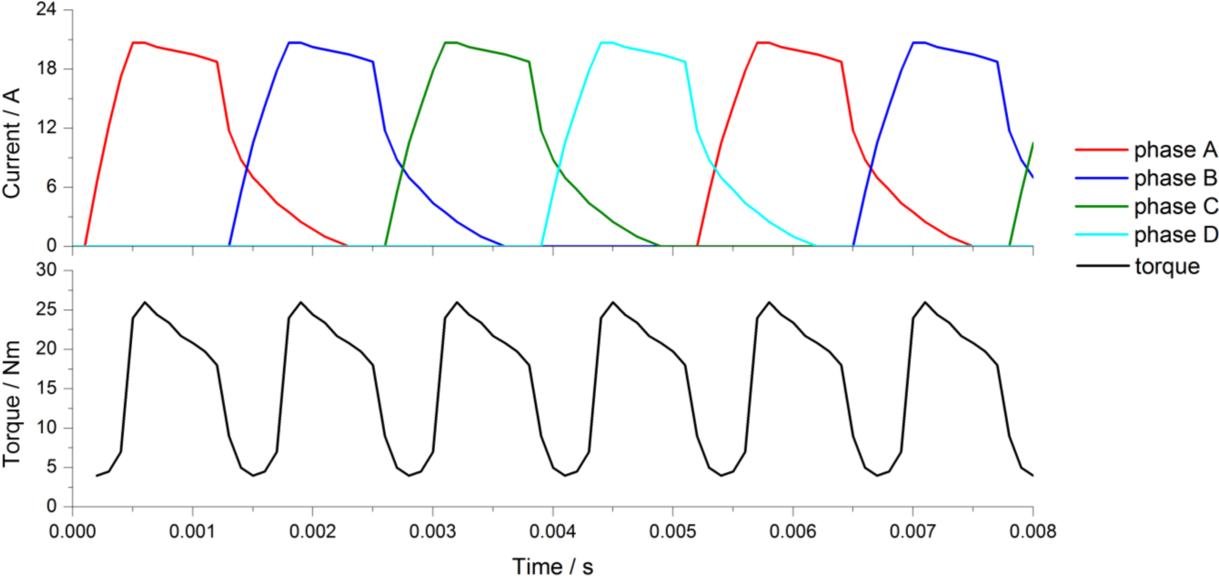
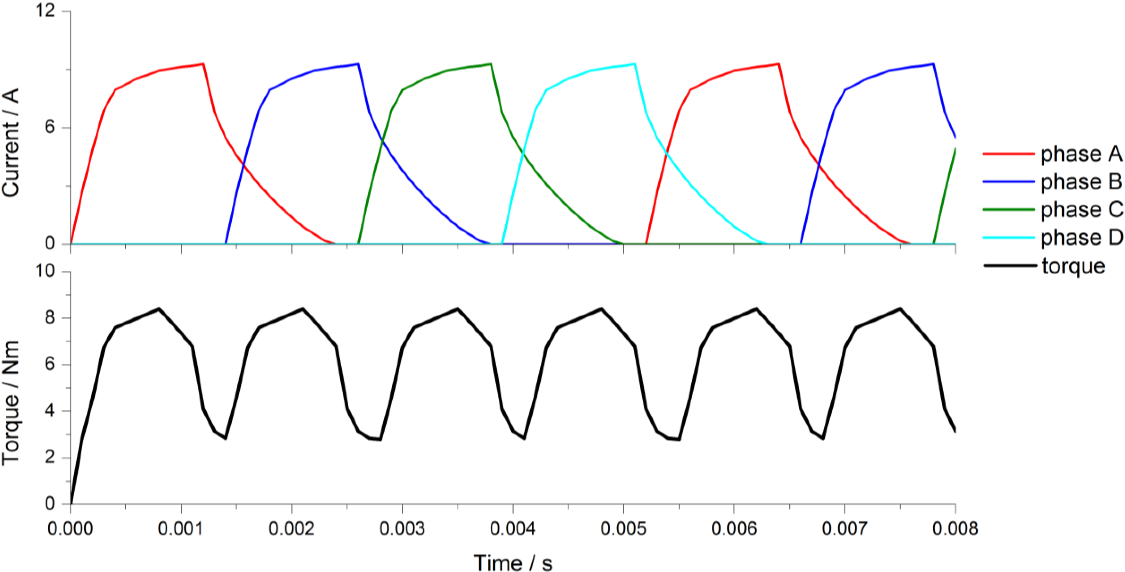
The control method is angular position control (APC), which is to control both the outer rotor and inner rotor by adjusting the turn-off and turn-on angles to obtain large current, high motoring torque, and low copper loss [
13]. The main power circuit is as shown in
Figure 7.
Figure 7.
The main power circuit of SRDRM.
Figure 7.
The main power circuit of SRDRM.
5. Experimental Results
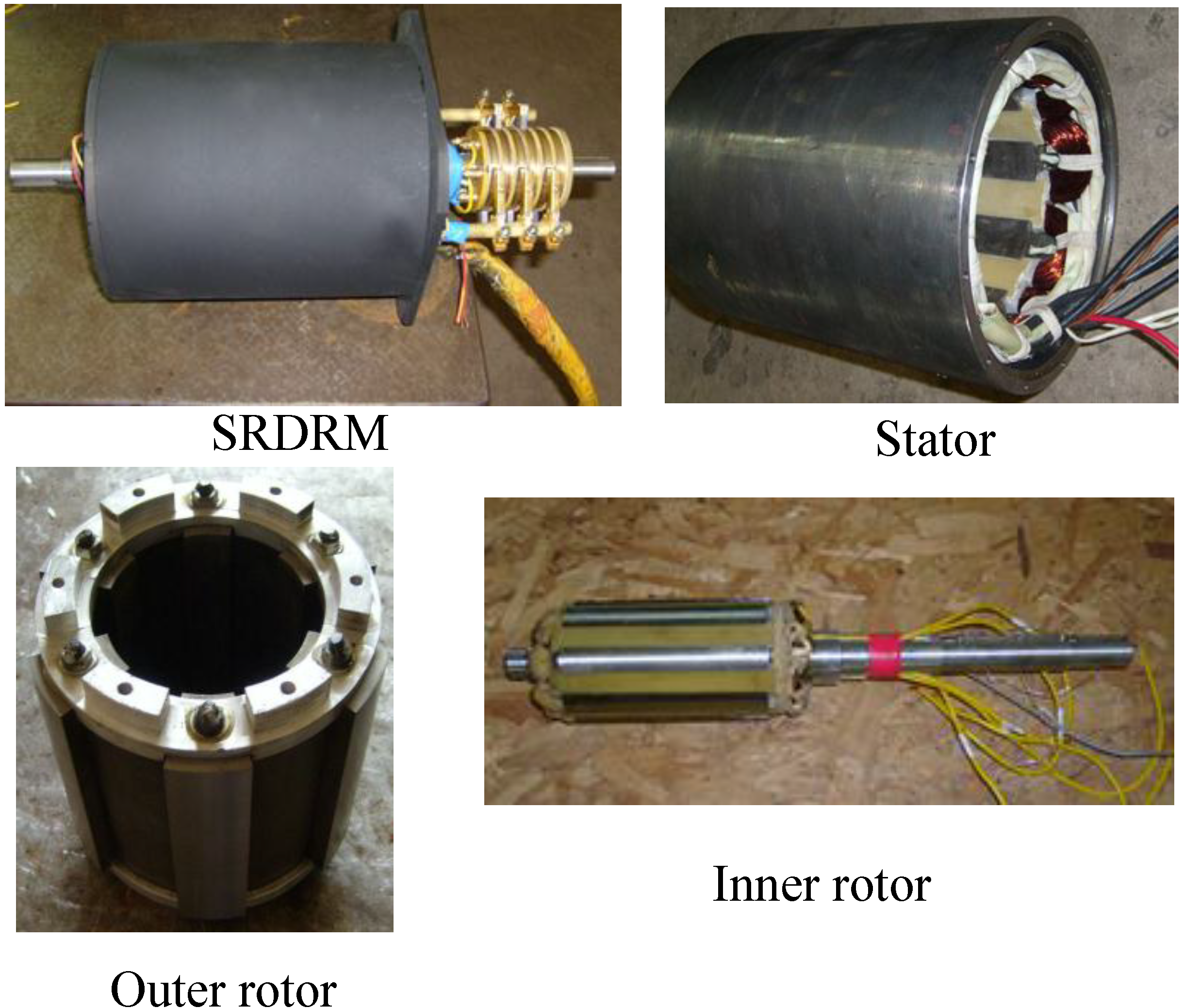
In order to verify the proposed design method, a 4.4 kW SRDRM is designed and manufactured.
Figure 28 shows pictures of machine’s prototype.
Figure 28.
Appearance of the prototype and stator/outer rotor/inner rotor.
Figure 28.
Appearance of the prototype and stator/outer rotor/inner rotor.
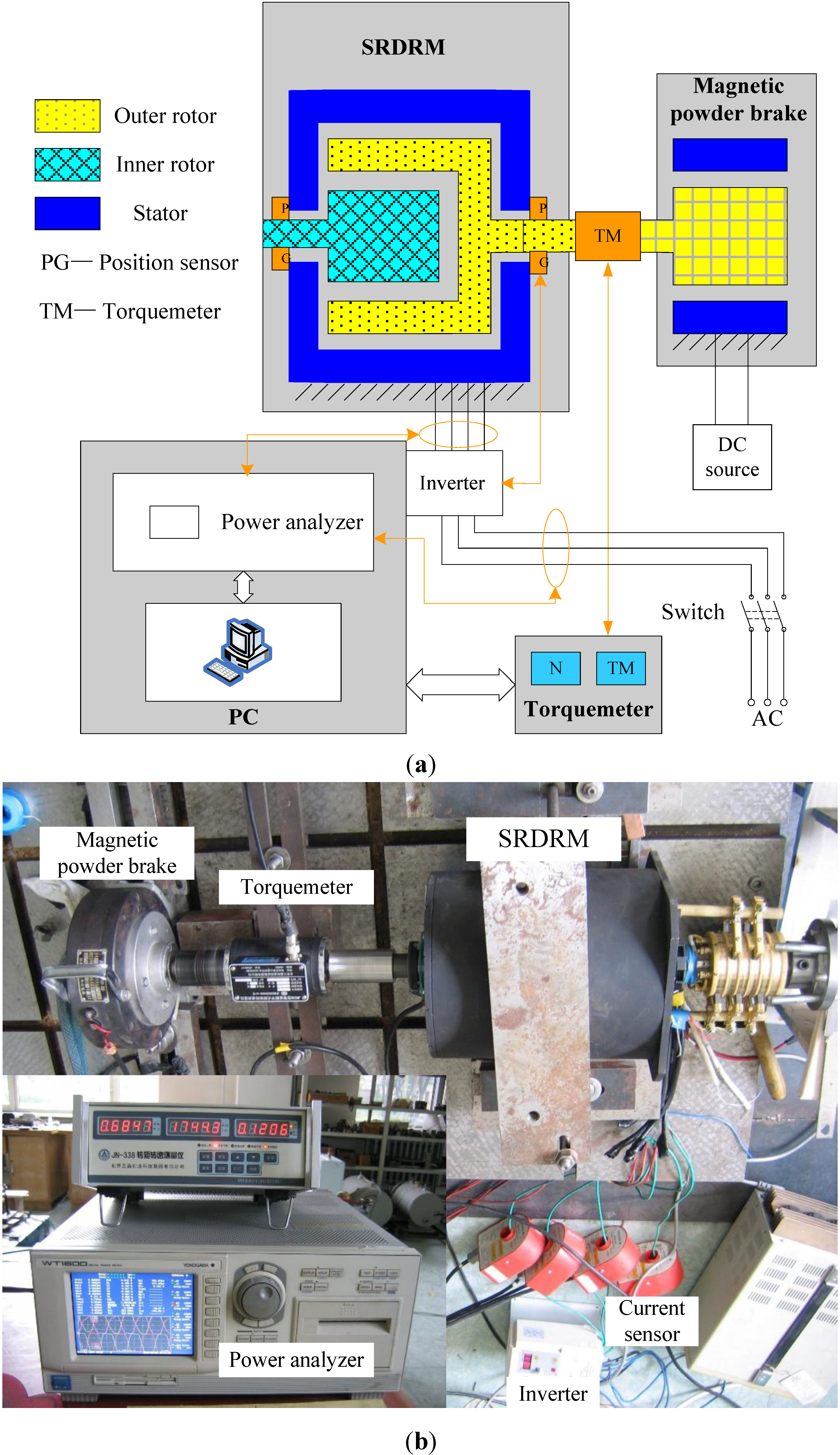
The SRDRM’s test bench mainly consists of SRDRM and its controller, magnetic powder brake, torque and speed sensors, power supply, and power meter, showing in
Figure 29. Because the limited condition of experiment, only the performance tests of inner motor and outer motor were completed. The focus of future work is the function testing and dynamic control experiment of SRDRM.
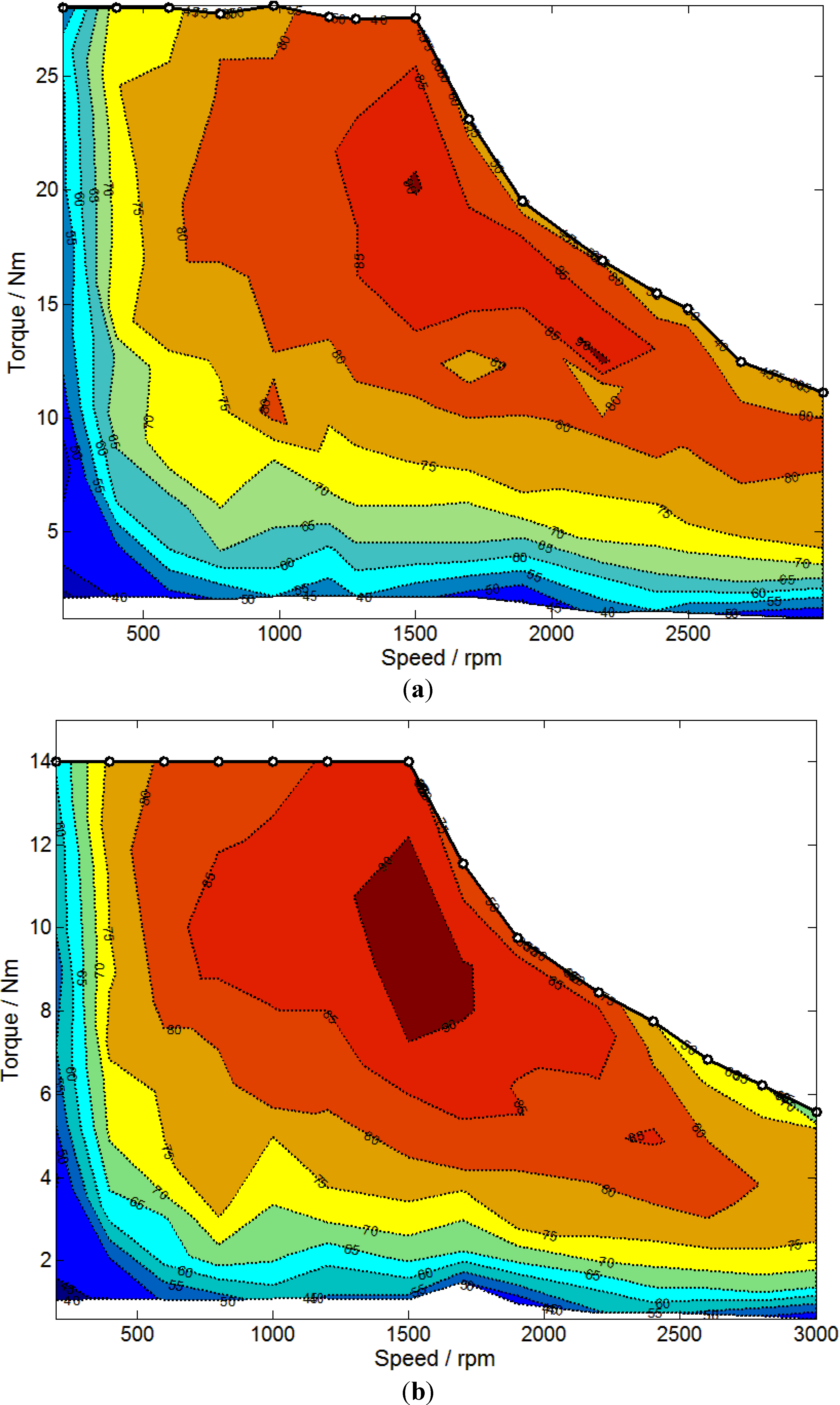
SRDRM’s efficiency Map and torque-speed profiles are shown in
Figure 30.
Figure 30a is the test efficiency Map of outer motor, and the maximum efficiency is 90.4% and the high efficiency region (the area that efficiency >80%) covers 45% of the operational area.
Figure 30b is the test efficiency Map of inner motor. Its maximum efficiency is 88.3% and the high efficiency region covers 30% of the operational area. From the experimental results, that the power of outer motor is greater than the designed value, while the power of inner motor is about half of that of the outer motor. Additionally, the maximum efficiency and high efficiency region are both smaller.
As can be seen from the experiment, the IM design is more difficult than the OM. Due to the structure of SRDRM, the effective core volume of IM is much smaller than the OM. Therefore, the inner rotor cannot hold enough conductors, which result in higher thermal load, higher magnetic load, and lower efficiency. Besides, because of the poor heat dissipation condition, the temperature rise in IM will be higher. When designing a SRDRM, in order to get the optimization result, it is better to design the machine from the inside to the outside.
Figure 29.
The experimental test bench: (a) Schematic diagram of test bench; (b) The experimental test bench.
Figure 29.
The experimental test bench: (a) Schematic diagram of test bench; (b) The experimental test bench.
Figure 30.
Test efficiency Map of SRDRM: (a) The efficiency Map of outer motor; (b) The efficiency Map of inner motor.
Figure 30.
Test efficiency Map of SRDRM: (a) The efficiency Map of outer motor; (b) The efficiency Map of inner motor.


