2.1. The Stirling Engine
2.1.1. Main Characteristics
A four-cylinder Stirling-cycle engine was selected to supply heat and electricity to the caravan. This SE is classified as a kinematic engine where the four cylinders are interconnected so that the expansion space of one cylinder is connected to the compression space of the adjacent cylinder. These pistons are driven by a wobble-yoke mechanism.
The cylinders are pressurized up to 28 bar with nitrogen, which works in a closed thermodynamic cycle [
9]. In this cycle, the nitrogen is continuously heated and cooled and the resulting changes in gas volume cause the pistons to move up and down [
6]. This linear motion is converted by a transmission system to a rotational movement driving a generator with permanent magnets. This generator unit produces DC electricity, which can be directly consumed or transformed into AC electricity.
The selected micro-cogeneration machine is one of the smallest Stirling engines on the market. It has reduced dimensions (450 × 500 × 650 mm3) and light weight (90 kg), useful characteristics for its application in smaller vehicles. The heat produced by the SE is used for space heating, and the power is used to meet the electrical needs of the caravan. The peak electrical power of the engine reaches 1 kW, and the maximum thermal energy is established at approximately 6.5 kW. As a basis for comparison, the conventional solution for the needs of a caravan are an ICE and a boiler to provide electricity and heat, respectively.
2.1.2. Operating Principle
SE accomplishes external combustion within a fuel combustion chamber. This method is used for heating the heat source and the working fluid. The selected fuel type was diesel with an LHV of 11.89 kWh·kg−1 because of its high availability at gas stations and higher energetic density. The low fuel consumption of the Stirling (roughly 0.7 L per hour of continuous run) guarantees long working periods between refills. The fuel combustion chamber heats the upper part of the cylinders. The lower portion of the cylinders is refrigerated by the circulating water, and this difference of temperature provokes a gradient of pressure that makes the pistons move. This linear displacement is converted to a rotational movement that moves the generator unit by means of a transmission system.
A water circuit collects the heat from the cylinders and from the exhaust gas through a condensing heat exchanger, and this recovered heat is used to supply space heating. This heat is carried out through fan coils or radiators distributed throughout the caravan.
Thus, the generator unit produces electricity only while the Stirling engine is running. This electricity can be used directly or it can be stored in batteries. Additionally, the production of electricity is linked to the production of heat. Although the production of heat is not linked to the generation of electricity, in this work, it will be assumed that the accumulation of electricity in the batteries will avoid the production of heat alone.
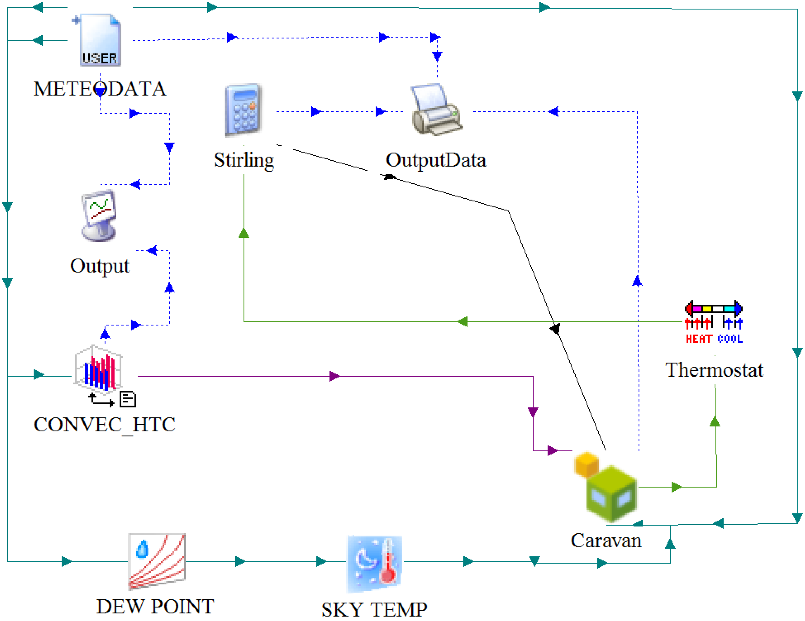
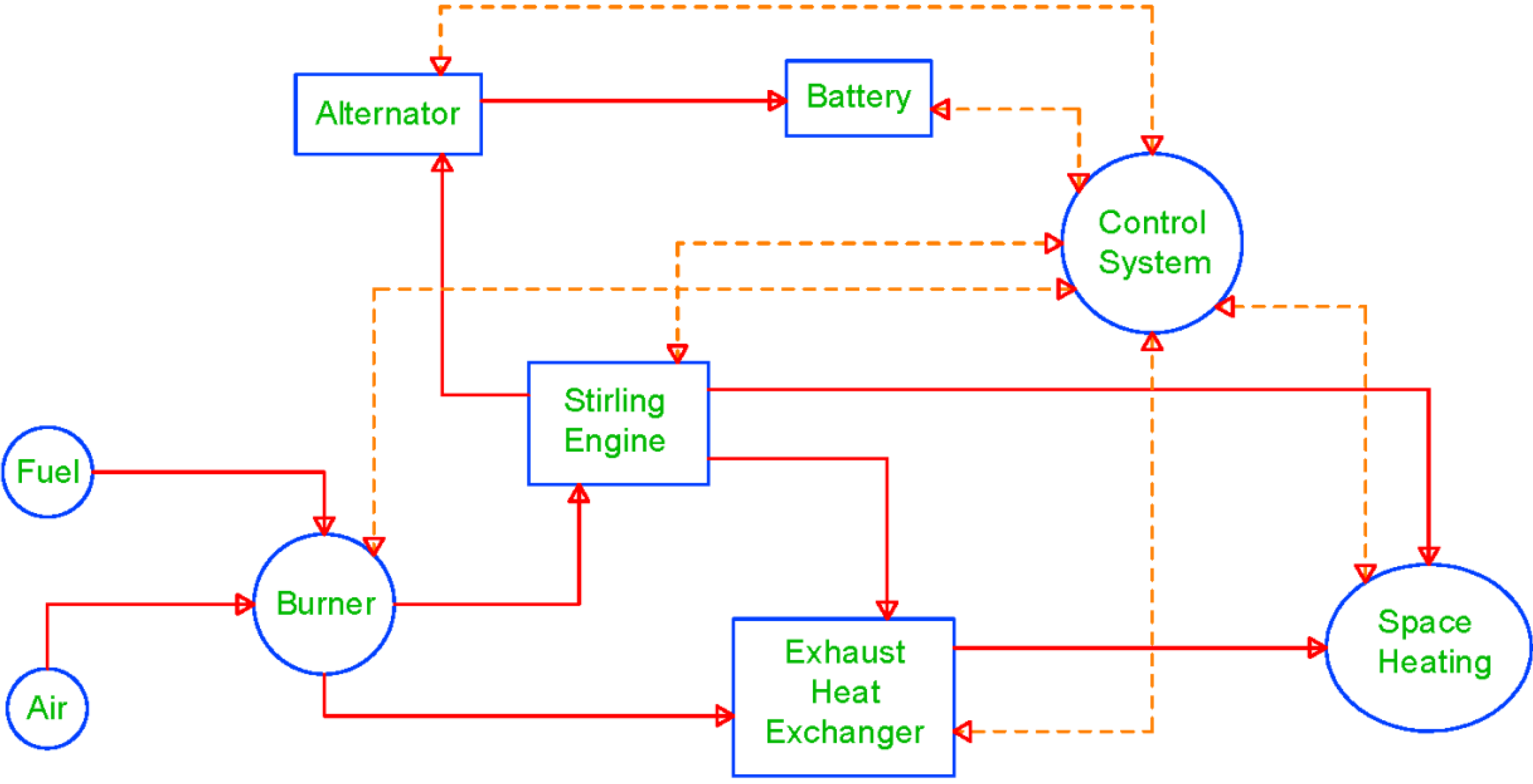
The working parameters are controlled by a microprocessor to maintain the engine in the optimal running condition and to maximize the obtained efficiencies as shown in
Figure 1.
An inverter is used to convert DC into AC depending on the current electrical needs. For optimal functioning of the SE, the cold source should be kept as cold as possible. Some SEs use a secondary refrigeration circuit to maintain the cold source temperature below a fixed value in the event that the cold source temperature is not low enough. In such systems, the use of such a secondary refrigeration circuit has to be considered a heat rejection.
Figure 1.
Operational scheme of the Stirling CHP system.
Figure 1.
Operational scheme of the Stirling CHP system.
2.1.3. Running Modes
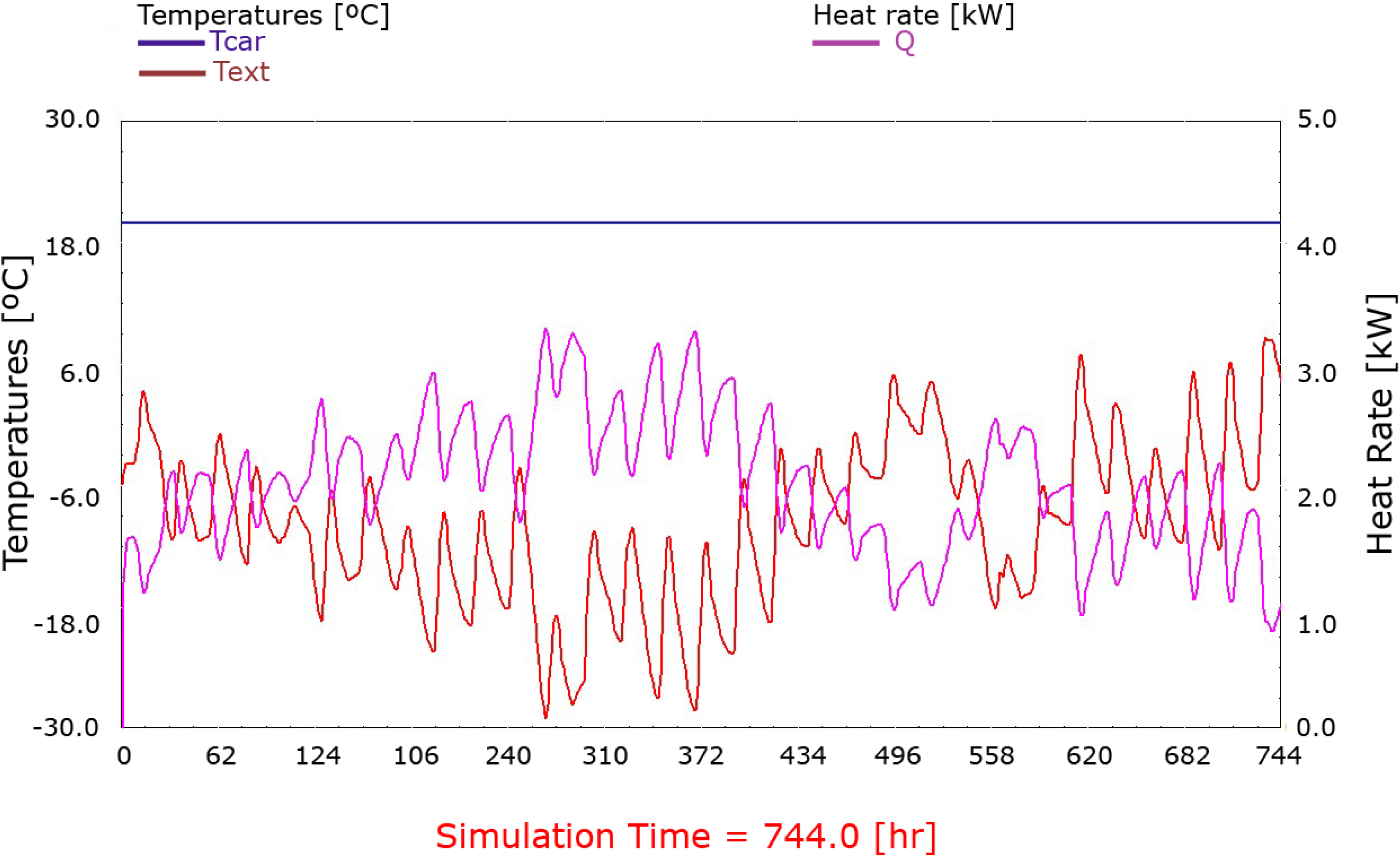
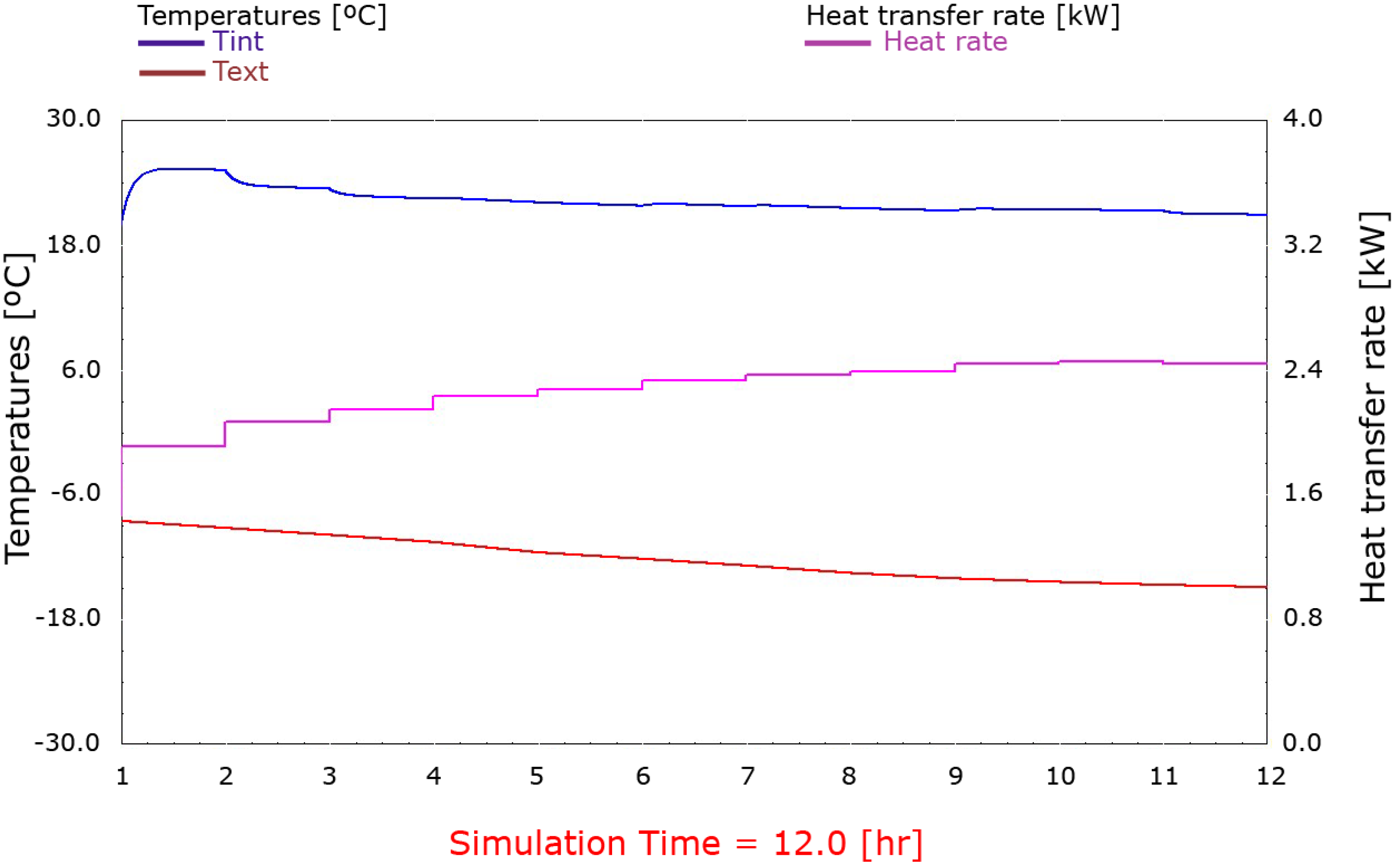
The SE employed can operate in two Heat Management Modes (HMM). If the HMM is on, the SE is commanded by a temperature set point. Otherwise, if the HMM is off, the system will run for a user-defined number of hours, or at least as long as the batteries are capable of absorbing the electricity produced (this mode is also called Autocharging). This Autocharging mode turns on the SE when the batteries’ charge level reaches a pre-set minimum value and stops when the batteries are completely charged or when a pre-set maximum number of running hours has been reached. As long as the HMM is off, the production of heat is considered a side-effect and the excess heat may therefore be rejected if necessary.
During the tests, the selected HMM was off in order to carry out the experiments with different electrical loads for studying the SE behavior. During this working mode, the heat produced by the SE was collected by the coolant and delivered into the space heating mechanism. To avoid the loss of heat rejected by the secondary circuit, both cooling circuits were connected to the same heat-sink.
Additionally, the SE allows the control of the coolant temperature flowing out of the system to be between 45 and 70 °C. The selected set-point temperature during the experiments was 60 °C, as this was considered a standard value for the radiators or fan coils of caravans and recreational vehicles.
2.1.4. Experimental Procedure
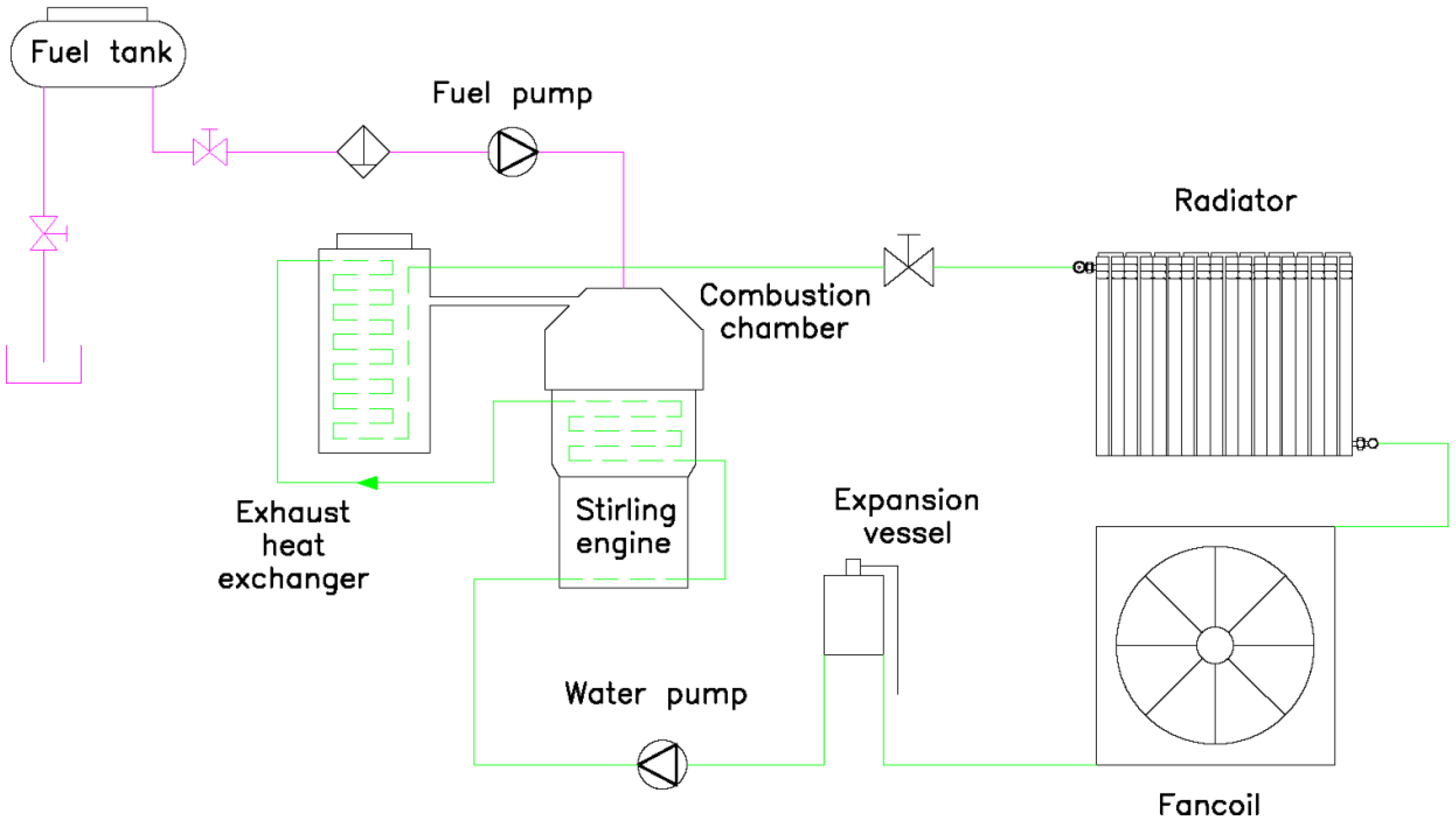
A test bench was built for testing the SE. This test bench contains four principal circuits: cogeneration system SE, hydraulic circuit, electrical circuit, and data acquisition system.
Essentially, the SE produces electricity and heat. Afterwards, the electric and the hydraulic circuits utilize these products to meet the needs of the caravan. The most important components are represented in
Figure 2.
Figure 2.
Schematic of the SE experimental setup.
Figure 2.
Schematic of the SE experimental setup.
The SE has been tested in the laboratory to obtain the nominal working parameters. For this purpose, the cogeneration system was subjected to different electrical loads. When the cogeneration system is turned on, the diesel is first burnt in the combustion chamber. This fuel supplies the necessary energy for expanding the nitrogen from the SE. The coolant inside the engine block provokes cooling of the nitrogen, and when the temperature difference between the hot and cold source is enough to expand and condense the nitrogen, the Stirling machine starts to turn. It has been observed that thanks to the reduced dimensions of this engine and the minimal thermal inertia, the heat source quickly reaches the nominal temperature; therefore, the system tends to predominately operate in a steady state. The electricity coming from the generator is stored in two 12 V DC and 100 Ah batteries connected in series. This electrical energy can be directly used in 24 V DC applications.
The coolant captures the heat from the engine block. Next, the coolant is carried through the exhaust gas by means of a condensing heat exchanger, and any extra energy is obtained. The exhaust gas temperature is maintained at approximately 90 °C. Directly afterwards, the coolant passes through a radiator and through a fan coil and additional thermal energy is taken from the coolant. This thermal power is calculated by measuring both the flow rate via a flowmeter and the temperature difference between the SE input and the output via temperature sensors.
The batteries are connected to a variable electrical load, which, in this case, is composed of diverse 24 V halogen lamps. The combination of these lamps allows the modulation of the electrical load in fixed steps between 350 and 950 W, which will simulate different caravan electrical loads. The performance of the system was studied within the eight electrical loads presented in the next section. Additionally, the battery current (input and output) is continuously measured by means of a Hall Effect ammeter. Other parameters, such as coolant temperature, battery voltage, exhaust gases temperature, exhaust gas composition, fuel injection frequency, etc. are also measured. In addition, fuel consumption is obtained by continuously weighing the fuel reservoir.
2.1.5. Experimental Results
Table 1 presents the thermal and electrical power in steady state conditions for different electrical loads as well as the measured fuel consumption.
Table 1.
Steady state results for different electric loads.
Table 1.
Steady state results for different electric loads.
| Test number | Electrical load (kW) | Electrical power (kW) | Thermal power (kW) | Consumption (kg/h) |
|---|
| 1 | 0.350 | 0.918 | 5.851 | 0.647 |
| 2 | 0.400 | 0.919 | 5.954 | 0.633 |
| 3 | 0.450 | 0.932 | 6.095 | 0.637 |
| 4 | 0.500 | 0.933 | 6.057 | 0.645 |
| 5 | 0.550 | 0.931 | 6.016 | 0.643 |
| 6 | 0.650 | 0.929 | 5.980 | 0.641 |
| 7 | 0.750 | 0.932 | 5.978 | 0.642 |
| 8 | 0.950 | 0.904 | 5.770 | 0.641 |
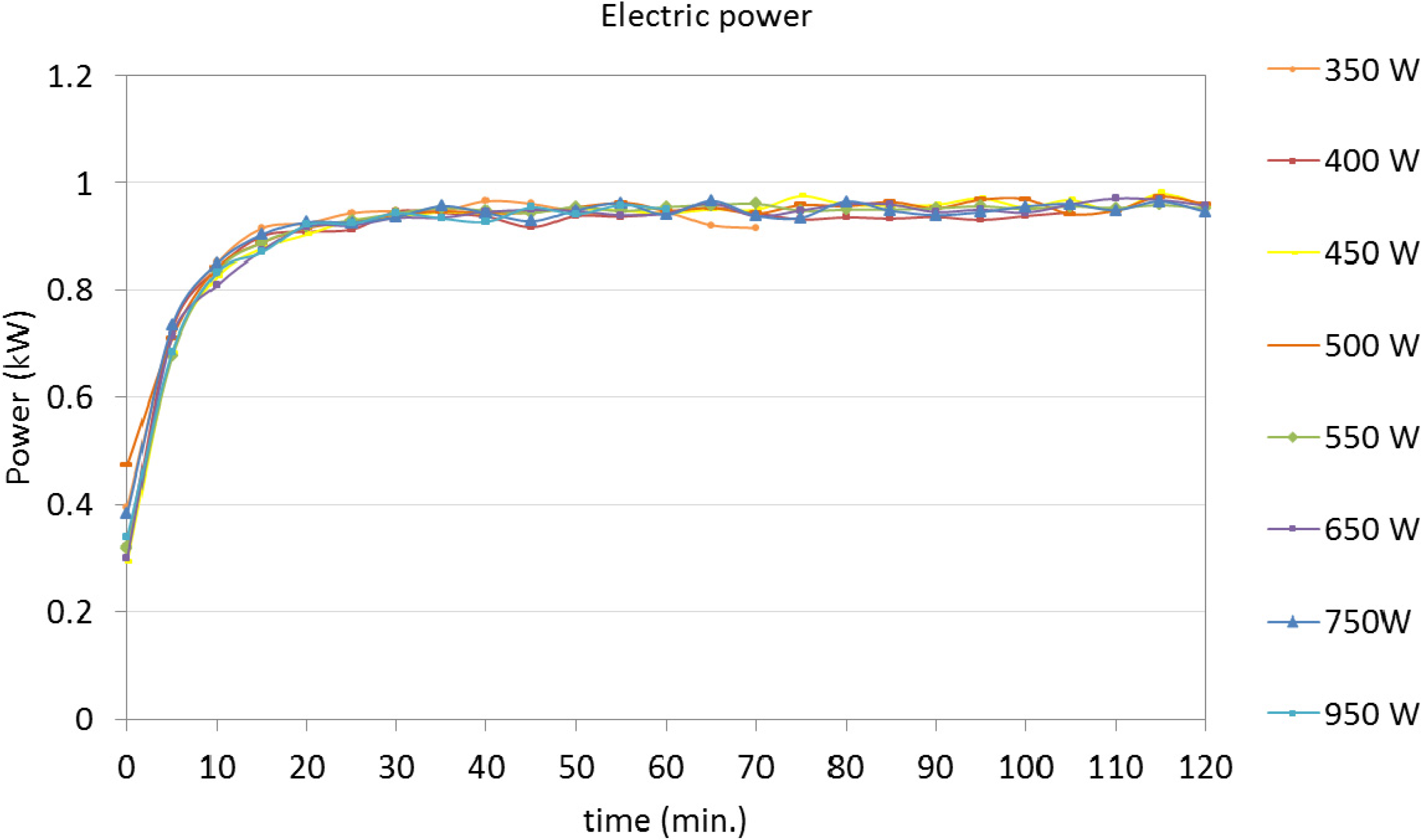
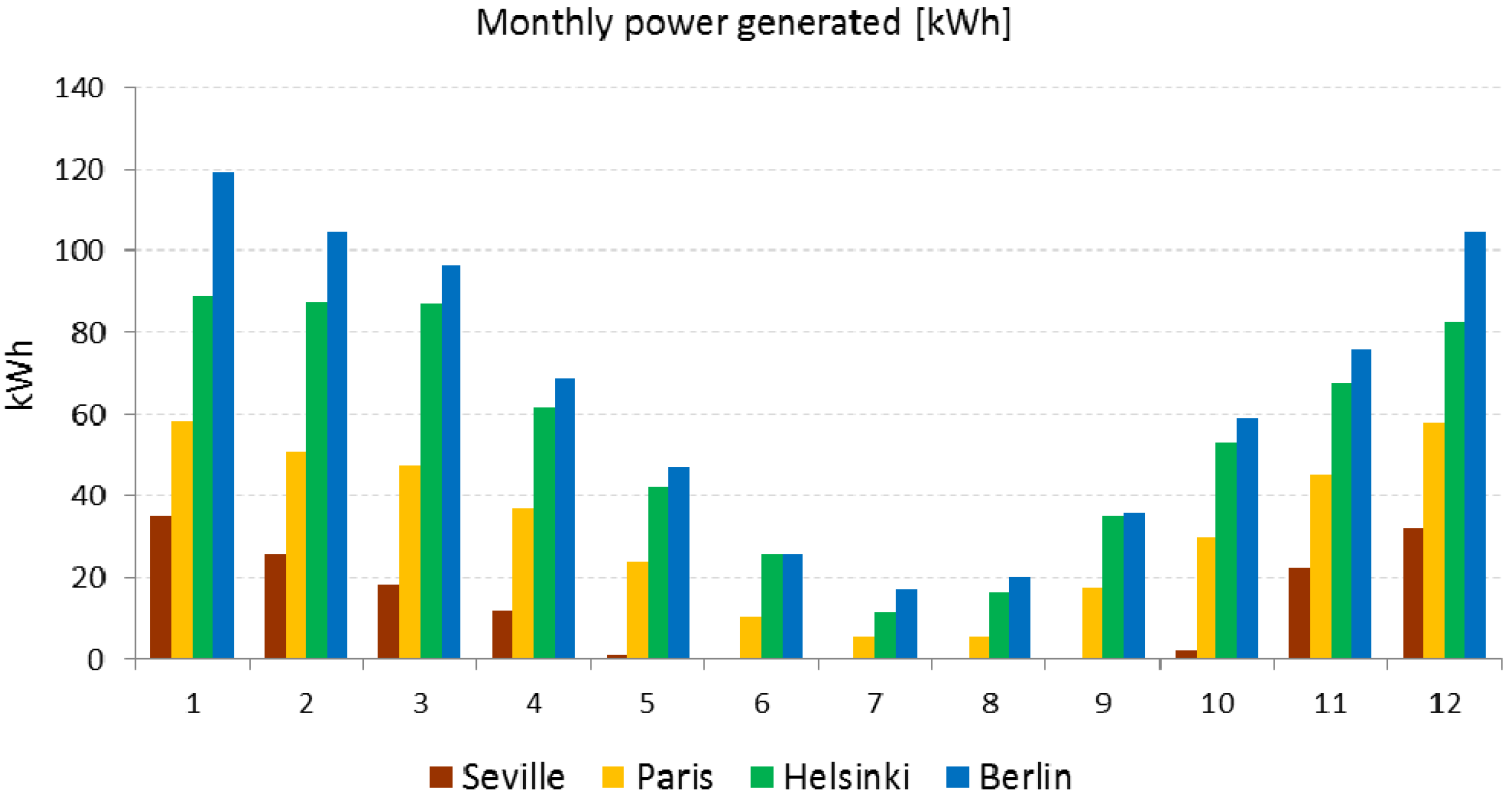
The electrical and thermal power results are presented in
Figure 3 and
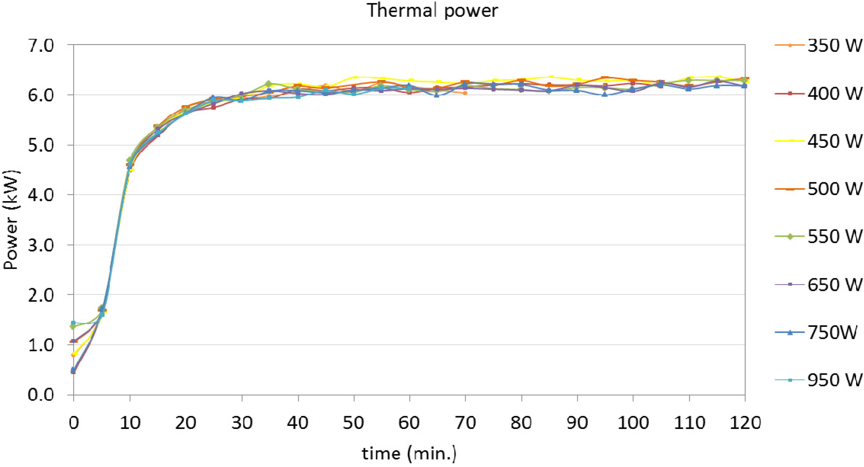
Figure 4, respectively. As shown, the SE reaches a single operation mode independent of the electrical load, which means that these components tend to operate at their nominal power to produce the maximum amount of electricity possible. The possibility of accumulating any excess electricity in the batteries allows for this type of regulation.
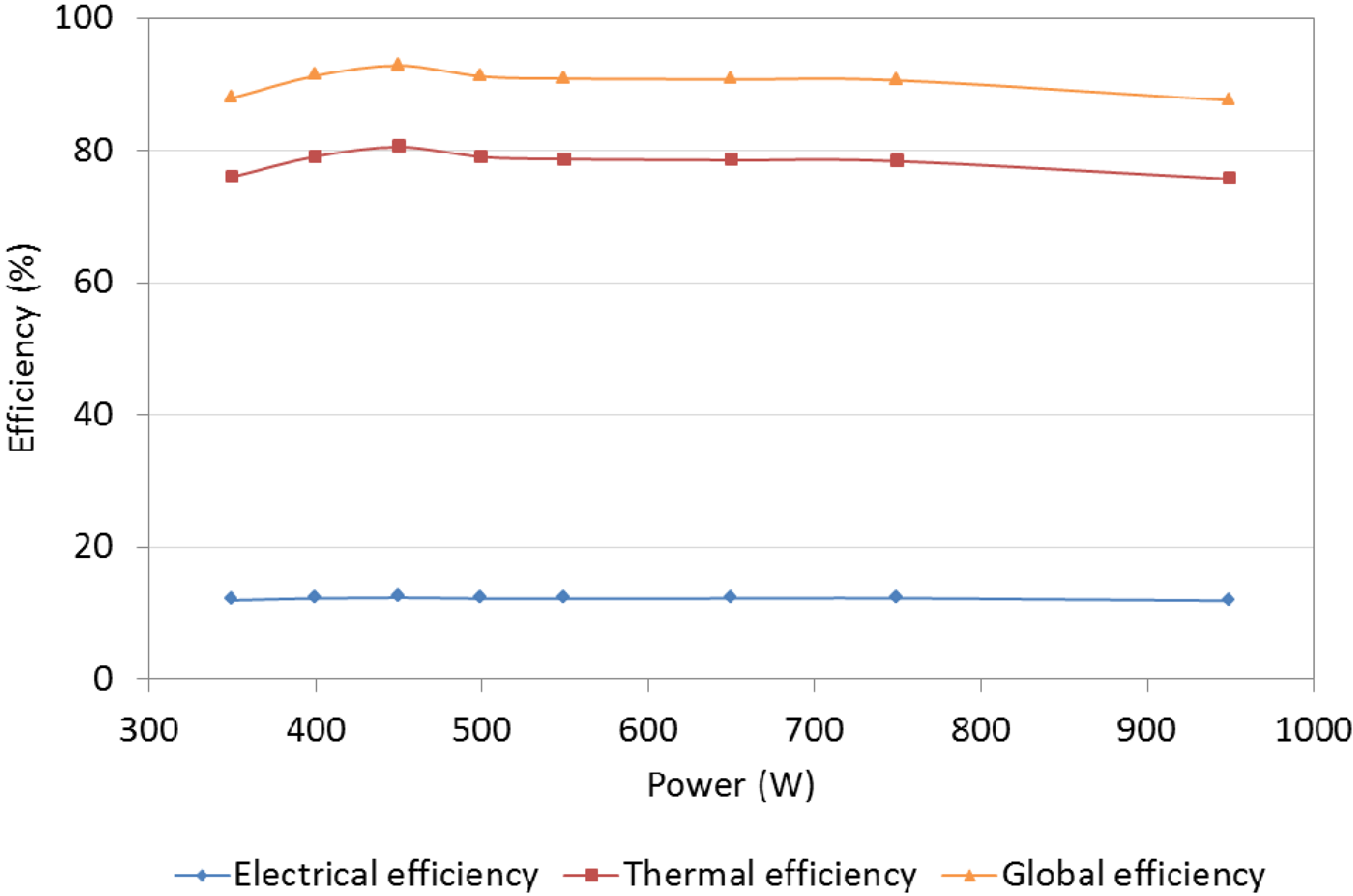
Because the simulation of the SE and the caravan was carried out during the night-time, the SE will work almost continuously, preventing machine cool down and avoiding any effect from periods of warm-up. The working point is clearly defined with a thermal power of 5.93 kW and an electrical power of 0.92 kW. The fuel consumption is also stabilized at 0.64 kg/h. These were the values introduced in the TRNSYS simulation tool. The mean value of the ratio between the generated heat and the generated electricity is 6:1, obtained at a high efficiency (91%), as shown in
Figure 5.
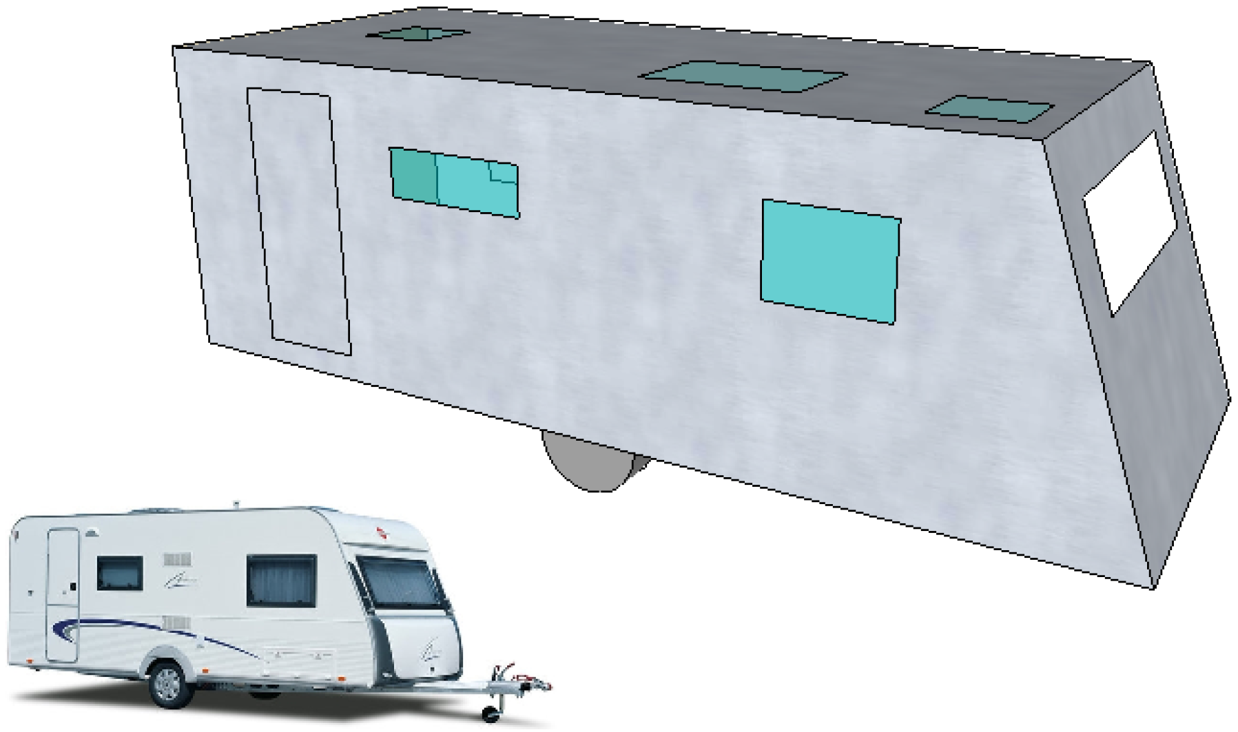
The composition and thicknesses of the walls, ceiling, and floor of the caravan are presented in
Table 2 and
Table 3.
Figure 3.
Power generated as a function of time for the different tests in kW.
Figure 3.
Power generated as a function of time for the different tests in kW.
Figure 4.
Heat rate as a function of time for the different tests in kW.
Figure 4.
Heat rate as a function of time for the different tests in kW.
Figure 5.
Efficiencies with different loads.
Figure 5.
Efficiencies with different loads.
Table 2.
Thermal properties of the layers of the walls and roof.
Table 2.
Thermal properties of the layers of the walls and roof.
| Dimension/Properties | Outer aluminum layer | Insulation polyurethane | Inner Plywood layer |
|---|
| Thickness (mm) | 1 | 26 | 3 |
| Thermal Conductivity (W/m·K) | 160 | 0.034 | 0.17 |
Table 3.
Thermal properties of the layers of the floor.
Table 3.
Thermal properties of the layers of the floor.
| Dimension/Properties | Outer aluminum layer | Insulation polyurethane | Inner Plywood layer |
|---|
| Thickness (mm) | 4 | 30 | 6 |
| Thermal Conductivity (W/m·K) | 160 | 0.034 | 0.17 |


