1. Introduction
Dimethyl ether (DME, CH
3OCH
3) is one of the most promising alternative fuels for diesel engines. It can be synthesized from natural gas, coal, or crude oil, as well as from non-fossil fuel feed-stocks (biomass and waste products). DME fuel is advantageous in compression ignition (CI) engines, with an oxygenated molecular structure composed of an oxygen atom (about 35% by vol.) between two methyl radicals (CH
3). Due to the absence of direct carbon-carbon (C-C) bonding, DME can drastically reduce or suppress the formation and development of soot during combustion in a compression ignition engine. Due to these benefits in diesel engines, DME is the most promising alternative fuel for diesel engines [
1,
2]. As mentioned above, CI diesel engines have many advantages such as low fuel consumption, high thermal efficiency, and good output characteristics and durability compared to spark-ignited gasoline engines. In actual diesel engines, there are two important problems: nitric oxides (NO
x) form through the combustion process after evaporated fuel mixes with air in the cylinder, and particle matter (PM) is produced in the fuel-rich regions [
3]. From the viewpoint of energy resources, the depletion of fossil fuel resources has resulted in a sudden rise of petroleum prices and limits on oil reserves. Also, environmental restrictions on exhaust emissions from motor vehicles have been strengthening. To meet the restrictions, various methods to reduce the generation of NO
x and PM during the combustion period in a diesel engine have been developed by many researchers [
4,
5,
6]. García
et al. [
4] showed that the homogeneous charge compression ignition (HCCI) combustion mode produces very low NO
x and soot emissions, but also noted some problems associated with HC emissions, fuel consumption, and difficulty controlling the start of ignition. In their work, the use of cooled EGR in an engine running in HCCI combustion mode resulted in ultra-low NO
x emissions. Also, they showed that soot concentrations from the HCCI combustion mode were negligible, and were relatively independent of the variation of EGR rate compared to conventional diesel engine mode.
In a diesel engine, a high-pressure injection system can reduce smoke emissions by improving fuel-air mixing and the spray atomization. Wang
et al. [
5] studied the influences on flame structure and soot formation of ultra-high pressure injection and the use of a micro-hole nozzle of diameter 0.08 mm using a high speed camera in a constant-volume chamber. They found that the impinging spray flame from the micro-hole nozzle at high pressure forms less soot and reduces the soot particle size. In their work, the use of ultra-high injection pressure of 200 and 300 MPa and the micro-hole nozzle has an obvious effect on soot reduction in the spray flame.
NO
x formation is a highly temperature-dependent phenomenon, occurring in diesel combustion when the temperature of the combustion gas exceeds 2000 K [
6]. Therefore, to minimize the generation of NO
x, it is necessary to reduce the maximum temperature in the combustion chamber. One simple method is to apply EGR, adding the re-circulated gas to the fresh air charge in the cylinder and lowering the oxygen concentration in the fuel-air mixture. DME is a desirable alternative fuel that can be synthesized from various non-fossil sources and has excellent ignition capability, with a higher cetane number than petroleum diesel fuel as listed in
Table 1 [
7,
8]. In comparison with conventional diesel, DME has an oxygenated molecular structure, higher latent heat and an absence of C-C bonding. Therefore, the use of DME fuel can considerably reduce the formation and development of soot during combustion in the engine.
Table 1.
Properties of DME fuel [
7,
8].
Table 1.
Properties of DME fuel [7,8].
| Properties | DME | Diesel |
|---|
| Liquid density (kg/m3) | 667 | 831 |
| Oxygen (%Wt) | 34.8 | 0 |
| Carbon (%Wt) | 52.2 | 86.0 |
| Hydrogen (%Wt) | 13.0 | 14.0 |
| Cetane number | >55 | 40–50 |
| Auto-ignition temperature (K) | 508 | 523 |
| Kinetic viscosity (cSt) | <0.1 | 3 |
| Lower heating value (MJ/kg) | 27.6 | 42.5 |
| Stoichiometric air/fuel ratio | 9.0 | 14.6 |
| Surface tension (at 298K, N/m) | 0.012 | 0.027 |
| Vapor pressure (at 298K, kPa) | 530 | <<10 |
Despite the extremely low soot emissions of DME-fuelled systems, many researchers have reported higher NO
x emissions from the engine [
9,
10,
11]. Therefore, the NO
x emissions from DME combustion in a diesel engine are a more serious problem than other emission types [
12,
13]. To reduce the NO
x emissions in DME-fuelled diesel engines, EGR systems or various after-treatment devices have been applied. In the case of DME fuel, it contains about 34.8% of oxygen content in the fuel composition and has a higher cetane number than conventional diesel, as well as better fuel evaporation and atomization characteristics [
2]. Therefore, DME combustion in a CI engine with higher EGR rate would be improved than the combustion of diesel fuel at same EGR rate.
Despite much research on DME, including DME spray atomization, combustion, and regulated exhaust emissions characteristics, the nano-size particle emissions and combustion characteristics of DME under higher EGR conditions have not yet been sufficiently investigated. Therefore, it is necessary to make a detailed investigation into the nano-particle emissions, reduced exhaust emission characteristics and combustion performance of a DME-fuelled engine with high EGR rate.
The objective of this study is to investigate the effect of varying EGR rate on the combustion and exhaust emission characteristics in a small common-rail direct-injection (DI) diesel engine fueled with DME. To analyze the combustion characteristics of DME fuel with high EGR rates, the combustion pressure, rate of heat release (ROHR), and IMEP were evaluated under changing fuel injection timings. In addition, to compare the concentrations of soot (FSN), ISNOx, ISHC, and ISCO emissions are also investigated under various engine test conditions. Also, the comparison of the effect of EGR rate fueled with DME on the total particle number and volume characteristics were also analyzed to consider the future emission regulations for alternative fuels.
2. Experimental Setup and Procedure
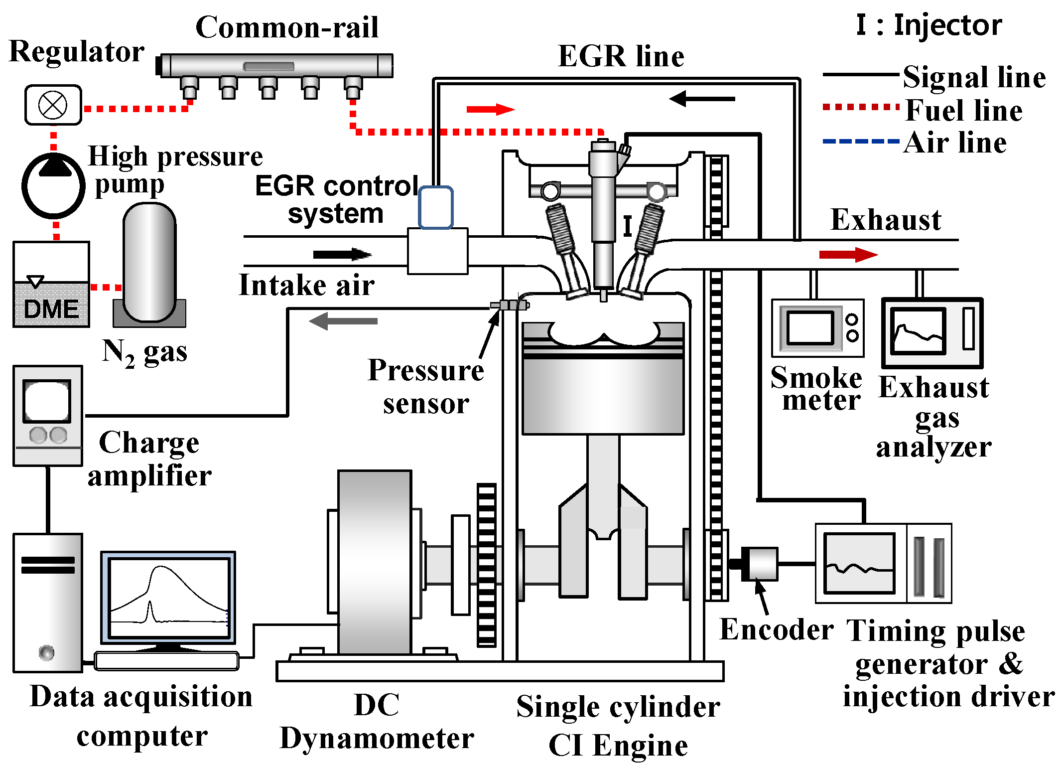
The experimental setup for the DME-fueled engine was composed of a DME fuel feed and high-pressure injection system, a DC dynamometer, an exhaust emission analyzer and a test engine (
Figure 1). The test engine was a single-cylinder DI diesel engine with displacement volume of 373.3 cm
3 and a 17.8:1 compression ratio. Detailed specifications of the test fuel and the engine and its injection system used in the experiments are listed in
Table 2.
Figure 1.
Experimental setup.
Figure 1.
Experimental setup.
Table 2.
Experimental test conditions.
Table 2.
Experimental test conditions.
| Test fuel | DME |
|---|
| Engine speed | 1200 rev./min |
| Coolant temperature | 70 ± 1 °C |
| Oil temperature | 70 ± 1 °C |
| Injection pressure | 60 MPa |
| Direct injection timing | 40° BTDC-TDC |
| Injection mass | 16.4 mg |
| EGR rate | 0%, 30%, 50% |
| Total equivalence ratio | 0.43, 0.61, 0.86 |
In this work, a direct-current (DC) dynamometer system with a maximum braking power of 55 kW was used to control engine speed and torque as well as to measure engine torque. To prevent vapor lock in the fuel feed line, the DME fuel system was pressurized by nitrogen gas, and the fuel pressure in the common-rail was pressurized by using two air-driven pumps (HSF-300, Haskel, Burbank, CA, USA). To measure the rotational signal of the crank angle, a timing pulse generator was coupled with a camshaft position sensor and a crank angle sensor. The injection duration of the DME and diesel fuel was controlled by using an injector driver (TDA 3300, TEMS, Daejeon, Korea).To implement EGR, a water-cooled EGR system was installed, including a control valve to regulate the EGR gas flow rate in the intake process. To control the EGR rate, the flow rate of intake air with EGR or naturally aspirated air flow was measured by using an intake air flow meter system (GFM 57, Aalborg, Denmark). In this experiment, the EGR rate is defined as follows:
where,
is the quantity of fresh air induced without EGR and
is the quantity of fresh air induced with EGR. The exhaust emissions were measured by using a NO
x analyzer (BCL-511, Yanaco, Kyoto, Japan), a HC-CO analyzer (MEXA-554JK, Horiba, Kyoto, Japan), and a soot analyzer (AVL-407, AVL, Steyr, Austria). Exhaust emissions were measured after the engine cycle operation had sufficiently stabilized. In this investigation, the indicated specific emissions were calculated as mass flow rates of pollutants per unit of power output, and the indicated specific exhaust emission for the concentration of component gas
ISEEXH is given by:
where,
is the mass flow rate of emissions,
n is the engine speed, IMEP is the indicated mean effective pressure,
Vd is the displacement volume, and
Z is the number of cylinders.
To improve the durability of the injection system, 1000 ppm of lubricity additive (539M, Lubrizol, Wickliffe, USA) was added to the DME fuel in the present study. In addition, to minimize changes in fuel pressure and temperature of returned DME fuel, these properties were controlled and maintained by using a pressure regulator and heat exchanger, respectively.
To reduce variation in the test results, all engine tests were performed at a constant speed of 1200 rpm, maintained using a DC dynamometer at a constant engine speed mode; coolant and oil temperatures were maintained at 70 ± 1 °C; and the fuel injection pressure was maintained at 60 MPa. The experimental investigation was conducted under a steady-state condition with injection mass of 16.4 mg (equivalence ratio Φ = 0.43), which is equivalent to 10 mg of conventional diesel fuel in terms of lower heating value (LHV). The investigation of high EGR rate combustion mode with DME fuel included EGR rates of 30% (Φ = 0.61) and 50% (Φ = 0.86), measuring the combustion, exhaust emissions, and nano-particle characteristics of each case relative to that without EGR combustion (0% EGR). The injection timing of DME fuel was varied from 40° BTDC to TDC (0°) in 5° steps of the crank angle. To reduce the effect of the induction of exhaust gas on the increase of intake air temperature, cooled-EGR was adopted. In addition, the intake-air flow rate, the exhaust gas temperature, gas pressure, gas flow rate, and EGR gas temperature were monitored to improve the exact control of EGR rate during the test.
3. Results and Discussion
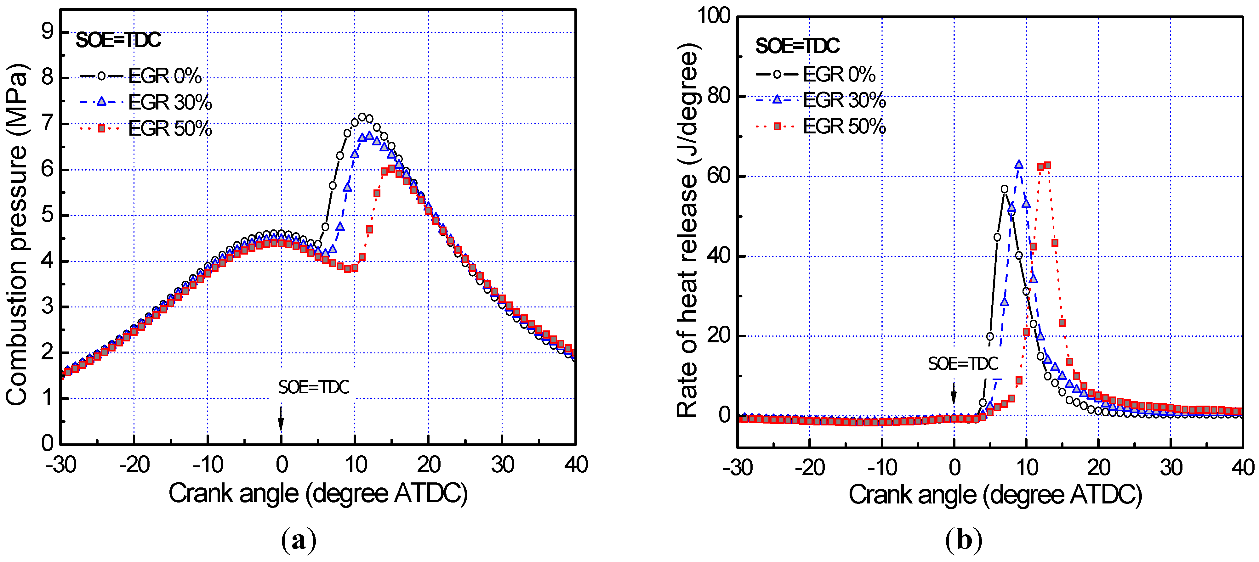
In a comparison of combustion pressure and rate of heat release (ROHR) of DME combustion using EGR rates of 0%, 30%, and 50% at different injection timings (
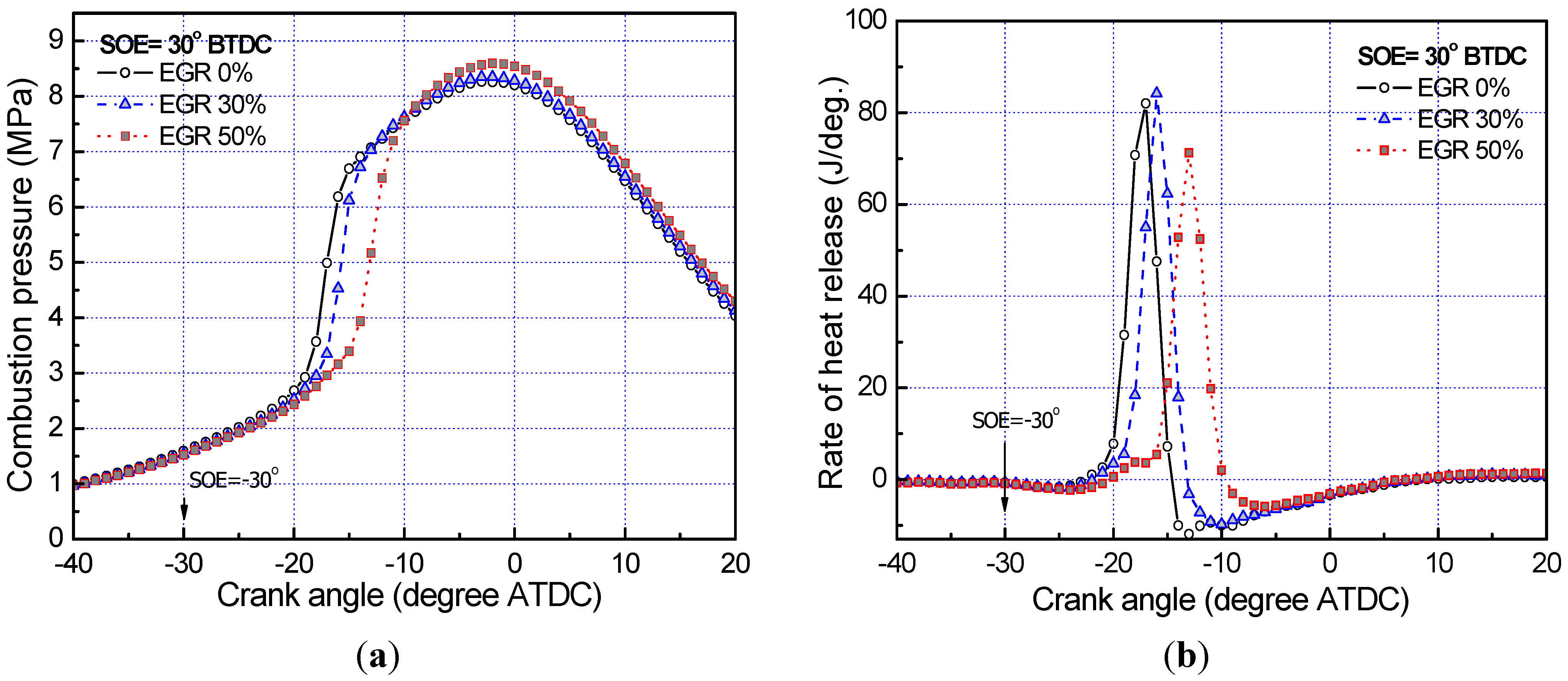
Figure 2), the profiles and patterns of combustion pressure and heat release for the three EGR rates had similar trends with variation of injection timing. However, ignition was delayed and combustion was prolonged with increasing EGR rate due to its thermal and chemical effects, including lower flame temperature. At an advanced injection timing (30° BTDC), ignition delays are considerably increased because of the dilution effects of EGR, and also because the low charge in-cylinder temperature creates a lean mixture, thus decreasing the peak release rate as shown in
Figure 3. In general, the use of high EGR rate lowers cylinder temperatures during the expansion stroke due to its greater heat capacity, thermal and chemical effects, with the most important effect being the dilution effect, which increases the ignition delay period and thus allows more mixing of the charge [
14]. Consequently, the heat-release rates will be dominated by the low-temperature premixed phase of combustion, thereby reducing the emissions of NO
x and soot simultaneously.
Figure 2.
Effect of EGR rate on combustion performance characteristicswith injection timing of TDC. (a) Combustion pressure; and (b) Rate of heat release (HRR).
Figure 2.
Effect of EGR rate on combustion performance characteristicswith injection timing of TDC. (a) Combustion pressure; and (b) Rate of heat release (HRR).
Figure 3.
Effect of EGR rate on combustion performance characteristicswith injection timing of BTDC 30°. (a) Combustion pressure; and (b) Rate of heat release (HRR).
Figure 3.
Effect of EGR rate on combustion performance characteristicswith injection timing of BTDC 30°. (a) Combustion pressure; and (b) Rate of heat release (HRR).
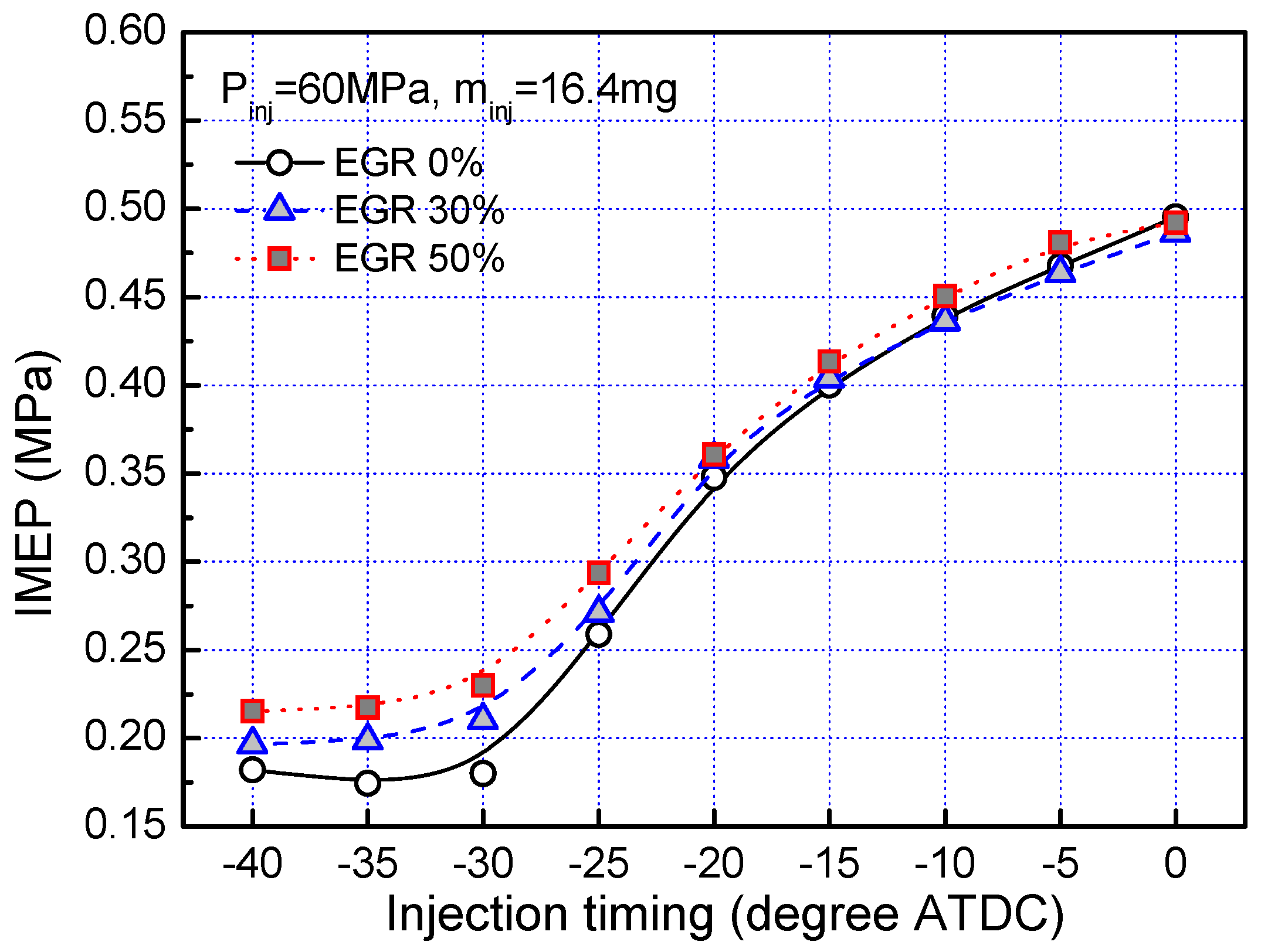
Figure 4 showed that the use of EGR slightly increased the IMEP because the heat of combustion was released between the end of compression stoke and the beginning of expansion stroke due to the prolonged ignition delay and combustion duration (recall
Figure 2 and
Figure 3).
Figure 4.
Effect of EGR rate on IMEP.
Figure 4.
Effect of EGR rate on IMEP.
In addition, as the injection timing advanced, the differences in IMEP caused by the application of EGR increased. It can be concluded that longer ignition delays and prolonged combustion durations for EGR combustions improved the conversion of combustion heat into the effective work process.
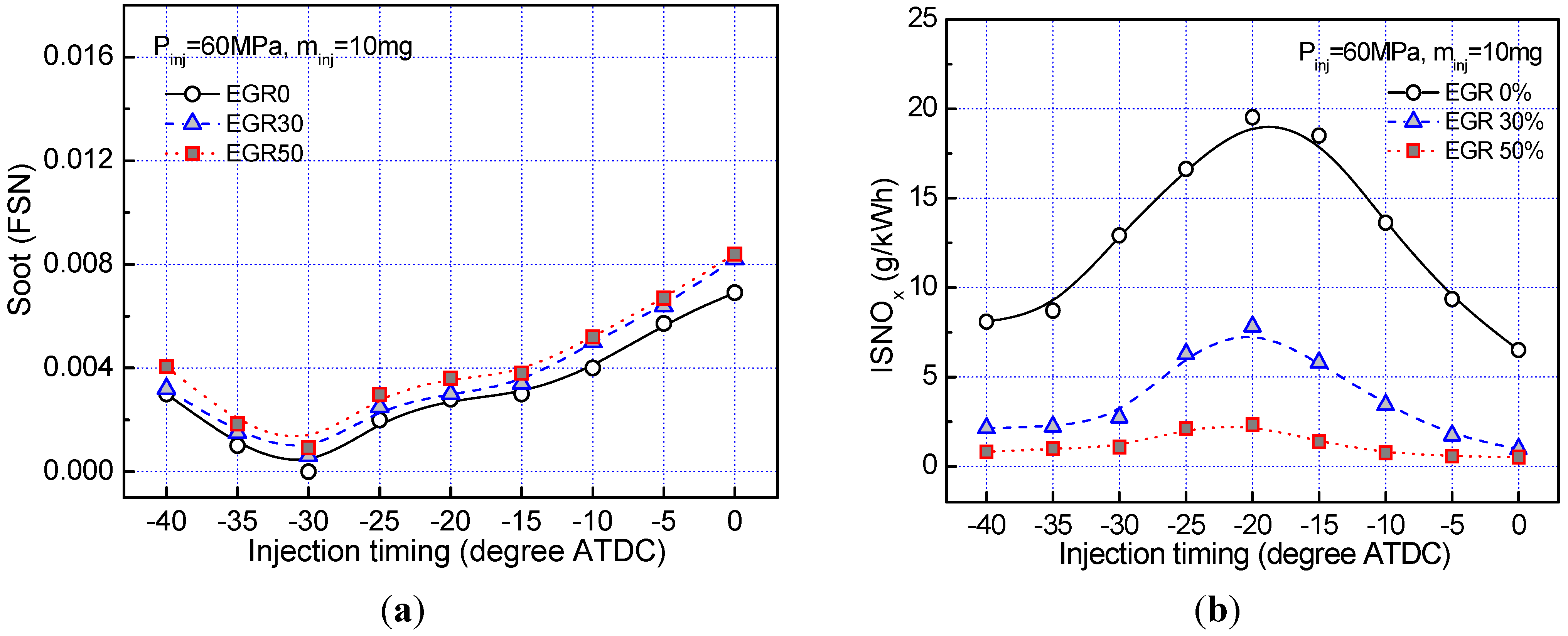
Figure 5a,b shows the effect of EGR rate and injection timing on the exhaust emission characteristics of soot and NO
x respectively. As shown in
Figure 5a, DME combustion exhibits extremely low level of soot emissions (FSN) at all injection timings in spite of EGR because the high oxygen content in DME, the absence of soot precursors and the short diffusion-controlled combustion phase suppress the soot formation.
Figure 5.
Effect of EGR rate on soot and ISNOx emissions: (a) Soot emission; and (b) ISNOx emission.
Figure 5.
Effect of EGR rate on soot and ISNOx emissions: (a) Soot emission; and (b) ISNOx emission.
In general, both soot formation and soot oxidation mechanisms are a function of combustion temperature and net soot release is maximized when the two mechanisms equally compete with each other. A decrease in combustion temperature due to higher EGR rate resulted in a significant reduction of soot formation in the engine than soot oxidation in the cylinder because insufficient oxygen concentration by higher amount of exhaust gas recirculation. However, if combustion temperature is higher than the location of maximum net soot release, the soot formation decreases more slowly than soot oxidation. In comparison with conventional diesel fuel, DME contains the fuel-borne oxygen content in fuel, which can be about 35% by mass, may promote a more complete combustion and thus effectively reduce engine-out emissions of particulate matter (PM), carbon monoxide (CO), and unburned hydrocarbons (UHC) in modern CI engines [
1,
2]. However, it produces an increase in emissions of nitrogen oxides (NO
x), which can be partially caused by the fuel property, has been observed in the use of oxygenated fuels [
9,
12,
13]. Another possible explanation for the increased NO
x formation in DME-fuelled combustion has been attributed to the lowered soot levels in the cylinder, thus lower radiation heat transfer results in higher gas temperatures. In
Figure 5b, 50% EGR combustion indicates very low NO
x concentrations. The reason for low NO
x is mainly due to the intake air dilution, thermal and chemical effects of EGR, as mentioned above. The quantity of EGR dilutes the oxygen concentration of the working fluid during the combustion processes. Concurrently, the EGR increases the specific heat capacity of the working fluid thereby reducing the flame temperatures. Furthermore, the endothermic dissociation of the EGR constituents such as H
2O may contribute to the reduction in the flame temperatures [
15]. Therefore, as the EGR is increased, the NO
x emissions relatively decreased as seen in this figure.
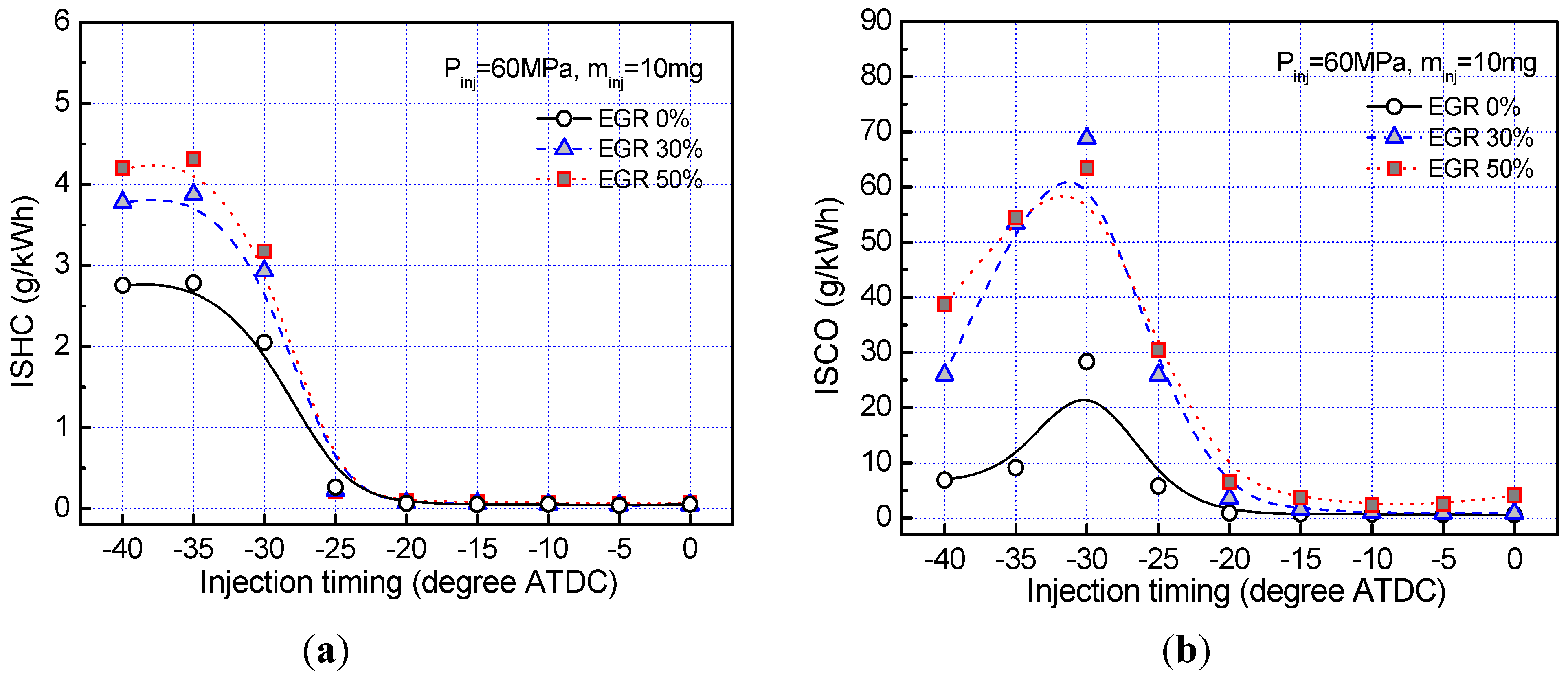
Figure 6a,b shows the concentrations of ISHC and ISCO emissions with 30% and 50% of EGR were slightly higher than those without EGR at conventional injection timing ranges from TDC to BTDC 20°.
Figure 6.
Effect of EGR rate on ISHC and ISCO emissions: (a) ISHC emission; and (b) ISCO emission.
Figure 6.
Effect of EGR rate on ISHC and ISCO emissions: (a) ISHC emission; and (b) ISCO emission.
These results can be attributed to the short diffusion combustion phase and the high oxygen content of DME. The high oxygen content and lower C-H ratio clearly resulted in a more complete combustion, and thus the production of unburned hydrocarbon and carbon monoxide emissions were suppressed despite the dilution effect of EGR. However, at the early (advanced) injection timings beyond BTDC 25°, especially for BTDC 30°, HC and CO emissions increased for all cases and for EGR cases were considerably higher than that of the 0% EGR case. The reason why this trend generally caused from the trapping of considerable amount of injected fuel in the crest volume during the prolonged ignition delay, greater possibility of forming unburned emissions by the crevice effect, and wall wetting phenomena at the higher EGR rate with early injection timings [
10]. High EGR rates also could reduce the combustion temperature to a fairly low level, promoting these emissions. In addition, early injection of fuel produces lower combustion temperatures, reducing the rate of completion of the CO to CO
2 reaction [
16]. In addition, these higher levels for soot, HC, and CO emissions are likely due to the fact that increased EGR leads one to increase the equivalence ratio of rich premixed flame that sits within the diffusion flame during the mixing controlled burn process.
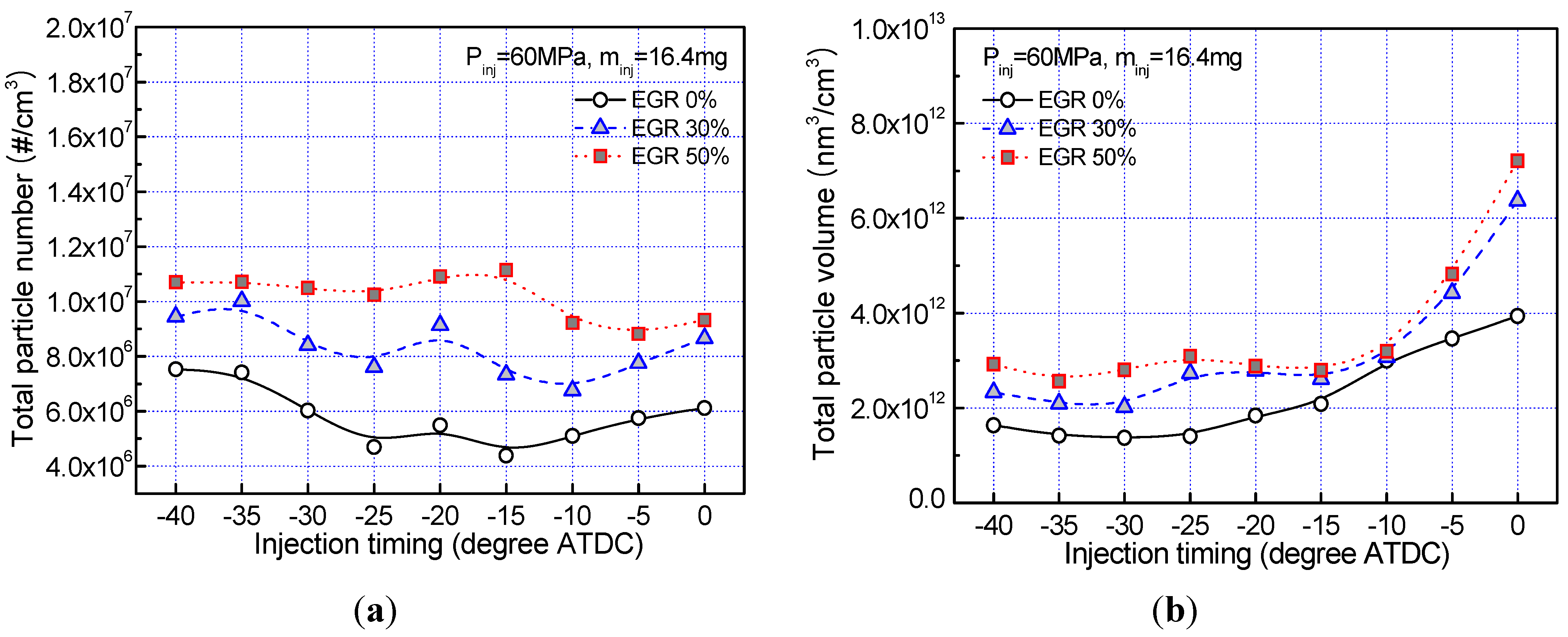
In
Figure 7, the effect of EGR rate and injection timing on the production of nano-particle was studied, in terms of both total particle number (#/cm
3) and particle volume (nm
3/cm
3).Both these measures increased with EGR rate over the whole range of injection timings. The trends with different injection timings and EGR rates also appear to match that of soot (FSN) emissions results (
Figure 5a). The increase in particle number and particle volume can be attributed to the dilution effect. In the TDC injection condition, the total particle number and volume are considerably increased in the high-rate EGR conditions relative to the 0% EGR condition. Under these conditions of delayed injection timing, the use of EGR slows combustion down and lengthens it into the expansion stroke so that the particle emissions can grow in number, volume and size due to increased condensation of volatile material in the combustion product gas at the expansion stroke after the end of the combustion, as well as condensation in the engine exhaust gas pipe [
17].
Figure 7.
Effect of EGR rate on nano-particle emissions: (a) Total particle number; and (b) Total particle volume.
Figure 7.
Effect of EGR rate on nano-particle emissions: (a) Total particle number; and (b) Total particle volume.
The simultaneous increase of particle number and volume may be due to concurrent processes of coagulation with homogeneous nucleation of metallic ash particles and heterogeneous nucleation of PAH and carbon soot on the metallic ash particle [
18,
19]. The engine operating conditions of EGR rate and injection timing can be optimized to minimize the particle emission characteristics of total particle number, particle volume and FSN results.

