Article

Performance of Thermosyphon Solar Water Heaters in Series

Energy Research Center, National Cheng Kung University, 2500 Section 1, Chung-Cheng South Road, Guiren, Tainan 711, Taiwan
*
Author to whom correspondence should be addressed.
Energies 2012, 5(9), 3266-3278; https://doi.org/10.3390/en5093266
Submission received: 3 July 2012 / Revised: 9 August 2012 / Accepted: 24 August 2012 / Published: 30 August 2012

Abstract

:
More than a single thermosyphon solar water heater may be employed in applications when considerable hot water consumption is required. In this experimental investigation, eight typical Taiwanese solar water heaters were connected in series. Degree of temperature stratification and thermosyphon flow rate in a horizontal tank were evaluated. The system was tested under no-load, intermittent and continuous load conditions. Results showed that there was stratification in tanks under the no-load condition. Temperature stratification also redeveloped after the draw-off. Analysis of thermal performance of the system was conducted for each condition.

1. Introduction

Solar thermal energy is a renewable energy source widely used worldwide [1]. Applications range from domestic solar water heaters (SWHs) to sophisticated solar farms for power generation. In particular, the relative simplicity and reliability of SWHs for hot water production in the domestic and commercial sectors has been proved to be economically viable, which has led to their widespread utilization [2,3,4,5,6,7,8].The basic elements of SWHs are collectors (flat plate or evacuated tubes), connecting pipes, a water storage tank, and auxiliary heating elements. To avoid damage from freezing or boiling, indirect heating SWHs would be adopted, in which a heat exchanger is used between the collector and the tank or within the tank [9]. Further, the tank could be installed either above the collectors (thermosyphon systems) or in a lower level (forced circulation). Prapas et al. [10] indicated that the thermal performance of thermosyphon SWHs is comparable to that of forced circulation systems.
With the good insolation conditions and economic incentives by the government, the use of SWHs is widespread in Taiwan (22°–25°N) [11]. The installed solar collector area is around 120,000 m2 per annum now, while there are only limited large-scale systems installed [12]. However, in industrial applications, the fraction of energy provided by the systems for producing hot water of 40–80 °C can be quite significant [3]. Thus, it is important for policy-makers to formulate effective countermeasures and strategies in dissemination of large-scale SWHs in Taiwan. Further, in such systems, water storage tanks are usually separated from solar collectors, and a forced circulation system is used. A reverse-type thermostat set at the desired temperature is fixed at the outlet of the collector. The booster pump switches on automatically when the outlet temperature equals or exceeds the set temperature of the thermostat. An example layout of a typical large-scale SWH is shown in Figure 1. Four collectors (an array) are arranged in parallel (cascade) with one inlet and one outlet to heat the cold water to a desired temperature, and the arrays are connected in parallel. Note that there might be no more useful energy gained by the system as an array comprising of more than three collectors. The true parallel arrangement yields maximum efficiency and economy [13].
Figure 1. Typical forced circulation solar water heater.
Energies 05 03266 g001
Thermosyphon SWHs have been widely used in the domestic sector, and various studies on their thermal performance have been conducted [14,15,16,17,18]. In general, solar energy adds energy to the fluid in the collector absorber. A density difference is created by temperature difference, and there is natural circulation of water (thermosyphon effect), in which the warm water rises and the cold water flows down. The thermal behavior of the systems involves a lot of interrelated parameters, such as solar radiation and weather conditions, the water flow rate through the collector, the tank configuration (vertical or horizontal), the effectiveness of the heat exchanger (for an indirect heating system) and the thermal load. The night heat loss (or thermosyphonic reverse flow) is another major concern [19]. In addition, to enhance the thermal efficiency, it is critical to prompt and maintain temperature stratification in the tank. At low collector flow rates, a thermosyphon tank can exhibit a large degree of temperature stratification since the cold inflow mixes only with the bottom layer. However, higher mass flow rate due to drawing off hot water from the tank will induce serious disturbances of the temperature stratification, and a fully mixed tank may result [20,21]. Jannatabadi and Taherian [22] further pointed out the phenomenon of thermal short circuit of temperature stratification, in which inlet cold water tends to go out of the tank before mixing with the stored hot water of the tank at certain draw-off flow rates.
Previous studies on thermosyphon SWHs were mainly on the performance of domestic systems. However, the connection of more thermosyphon SWHs might arise in an application when considerable hot water consumption is required, resulting in higher mixing and less temperature stratification inside each tank and between tanks [23]. In this study, eight commercial direct-heating thermosyphon SWHs (1.43 m2 collector surface area; 125-litre water storage tank capacity) were used. For the no load case, thermosyphon mass flow rates and temperature stratification in the tank were evaluated. Then the eight tanks were connected in series. The experiments were conducted at both intermittent and continuous load conditions, and system performance characteristics are presented.

2. Experimental Setup

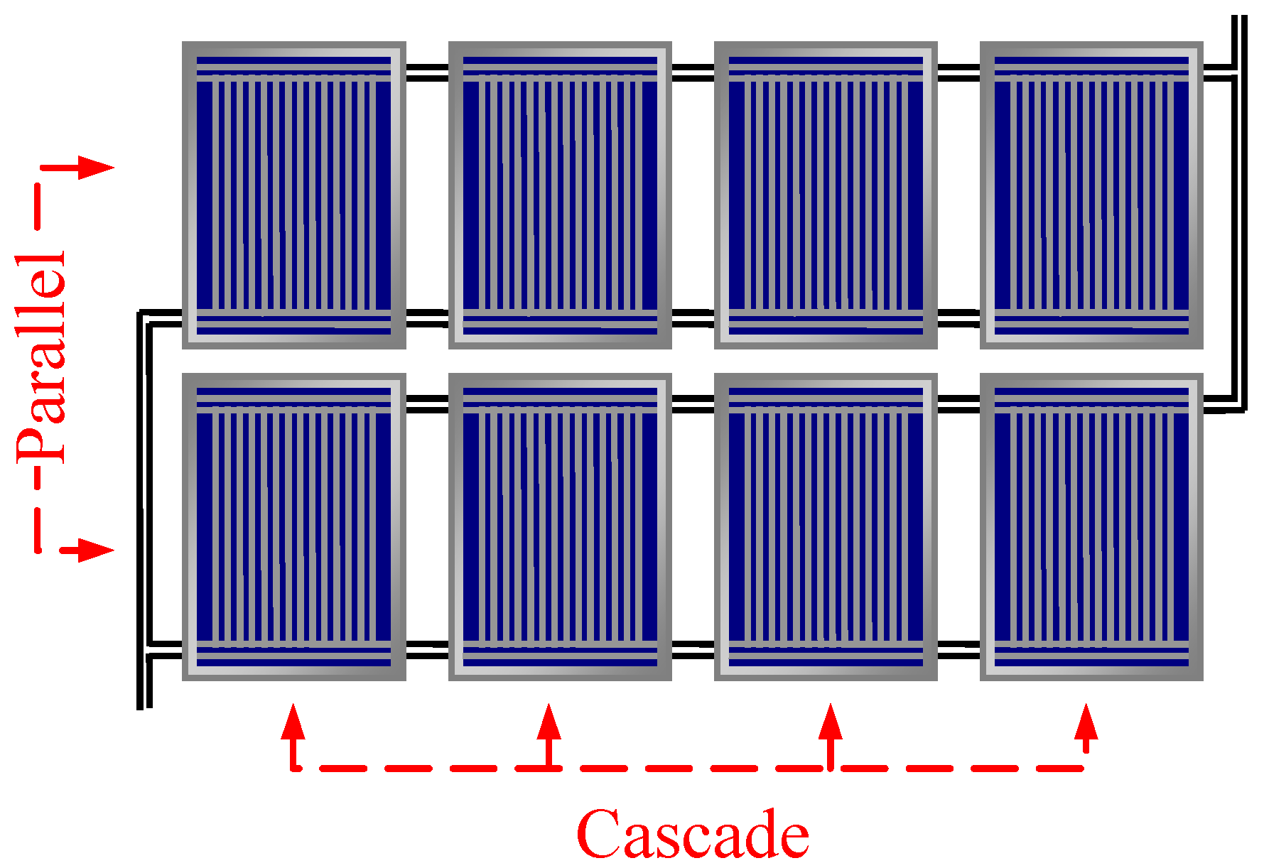
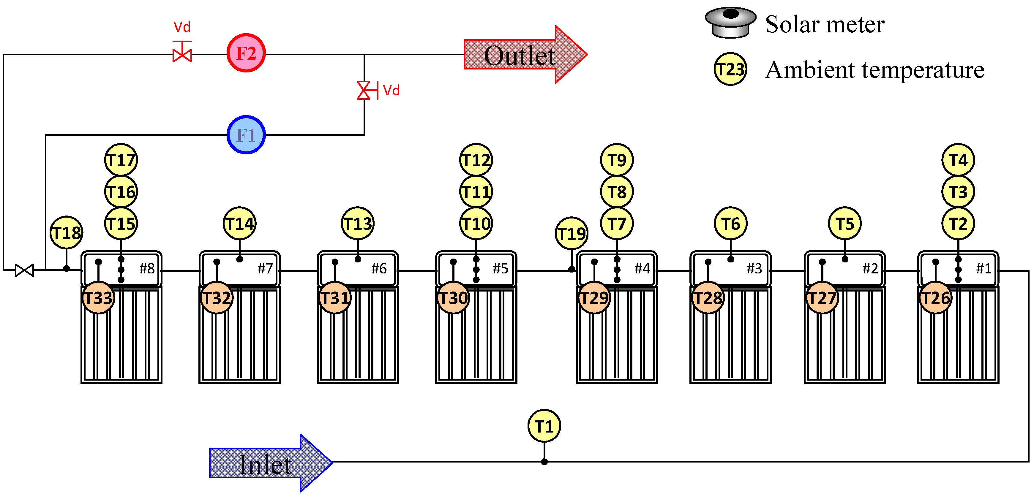
2.1. Experimental Apparatus

For this experimental investigation, typical commercial direct-heating thermosyphon SWHs manufactured in Taiwan were employed. The main technical characteristics for the SWH are given in Table 1. It consists of a flat-plate collector having an effective area Ag of 1.43 m2, facing south and tilted at 30° from horizontal, and an insulted horizontal tank (125 L). Note that water enters and exits the bottom and top of the tank, respectively. A single SWH was tested according to the Chinese National Standards CNS 12558-B7277, which is an outdoor test method. The test conditions specify the daily solar radiation per square meter G (≥7 MJ/m2), the average wind speed (<4 m/s), water initial temperature Ti and ambient air temperature Ta. The thermal efficiency η (= mCp(TfTi)/(AgG)), given as the ratio of useful heat absorbed by a SWH to incoming solar energy on solar collectors, is 0.55. Note that Cp and Tf are the specific heat and final water temperature in the tank, respectively. A schematic diagram of the test setup is shown in Figure 2. Platinum resistance thermometers (Chancemore Electrical Co. Ltd., Pt 100) were inserted into each tank at locations of 30, 68, 190 and 312 mm below water level to monitor the local water temperature (T26–T33, T2–T17). T1 and T18 are the locations for measuring the water temperature at the inlet and exit of the system. Solar radiation was measured by means of a precision spectral pyranometer (Eppley Laboratory, Inc., Model PSP) installed on a horizontal surface, and accuracy of the measurement is estimated to be ±0.2%. Water flow rates were measured by two flow meters in the draw-off line, in which a flow meter HTL20-S1-F0-A (F1, Shin Yuan Precision Machinery Co., Ltd.) was employed at higher flow rates, and an electromagnetic flow meter (F2, Siememns AG Co., Model MAGFLO) was employed for lower flow rates. Data from all monitoring devices were sampled every 10 seconds by a data acquisition system (ICP DAS CO., LTD., Models ET-7017 and ET-7015).
Table 1. Main technical characteristics of the direct-heating solar water heater.
Collector aperture area1.43 m2 (1471 mm × 970 mm)
Collector cover materialSingle tempered glass, 3 mm thickness
Collector channel24 tubes of 8 mm internal diameter
Collector absorberNon-selective absorbing surface-SUS444
Collector slope 30°
StorageHorizontal tank, volume: 125 L
Figure 2. Experimental layout.
Energies 05 03266 g002

2.2. Water Draw-off Profiles

The experiments were conducted under both no-load and loaded conditions, with intermittent and continuous loads imposed. For all tests, the auxiliary heaters were not activated. All tanks S1–S8 were filled with cold water the previous night. Three hot water draw-off profiles (DP-I, DP-II and DP-III) were selected, as shown in Table 2. The flow rate m ˙ was fixed at 5 L/min (LPM), and all had a total draw of 750 L. Several tests were conducted for each profile. It is also noted that the DP-I and DP-II profiles would represent the actual situation for industrial applications. The DP-III case could simulate the hot water consumption pattern of SWHs for a dormitory. For the continuous load cases, the tanks were also filled with cold water the previous night. m ˙ was 0.8, 1.7, 5, and 10 LPM, and all had the maximum draw of 1500 L. Thus, the test time is flow-rate dependent. The climatic conditions are also given in Table 3, where I the average values of solar radiation intensity during the test period. Note that CNS 15165-1-K8031-1 is in compliance with current international standards to determine steady-state and quasi-steady-state thermal performance of solar collectors under natural solar radiance for a solar collector using a flow rate of 0.02 kg/m2, which corresponds to 1.7 LPM in the present study. For comparison, the flow rate of a typical tap for bathing is 5 LPM.
Table 2. Intermittent load conditions.
TimeDP-IDP-IIDP-III
10:00250 L (50 min)125 L (25 min)
11:00 125 L (25 min)
12:00250 L (50 min)125 L (25 min)
13:00 125 L (25 min)
14:00250 L (50 min)125 L (25 min)
15:00 125 L (25 min)750 L (150 min, 15:30–18:00)
16:00 125 L (25 min)
Table 3. Climatic conditions, continuous load cases.
Test conditionDateTest periodI, W/m2Ta, °C
10 LPM2011.06.1009.45–11:2578333.9 ± 0.7
5 LPM2011.06.1510:15–13:4582634.0 ± 2.0
1.7 LPM2011.04.0810:00–16:0079128.5 ± 1.8
0.8 LPM2011.04.1510:00–16:0072129.4 ± 1.5

2.3. Data Reduction

As mentioned above, temperature stratification of the tanks has a direct influence on the thermal efficiency of SWHs. Typical temperature distributions inside the S4 tank for the no-load case are shown in Figure 3. It can be seen that the temperature at the lower section remains relatively unchanged during the initial operation. Towards the end of the operation period, the temperatures inside the tank reached maximum values and then slightly decreased. The solar collectors would act as a thermal emitter at night, resulting in heat loss from the tank to the collectors. The measured value of the temperature difference in a tank was used to calculate thermosyphon flow rate m ˙ t h e r [24], as given in Equation 1:
m ˙ t h e r = M / Δ t
where M is the water mass in each section and Δt is the time-lag when the measured temperatures at the upper and lower section in a tank are the same. Note that the ideal m ˙ t h e r would be about 0.01–0.015 kg/(m2 s).
For the intermittent load cases, the useful energy transferred was evaluated from the measurement of inlet temperature of the first tank Tin and outlet temperature of the last tank Tout, and the thermal efficiency of the system is given in Equations 2 and 3:
Q = m ˙ C p ( T o u t T i n )
η = Q / I A G
With the continuous load conditions, cold main water entered the tank bottom with hot water withdrawn from the upper part of the tank continuously. The amount of solar energy carried out when hot water being drawn from the tank ΔQoutput which was evaluated from continuous integration of inlet Tin,i and outlet temperatures Tout,i of each tank (T26–T33). The output solar energy ΔQoutput and the discharging efficiency η1 of each SWH are given in Equations 4 and 5. Note that the outlet temperature of ith tank Si is taken as the inlet temperature of (i + 1)th tank Si+1 (Tin,i = Tout,i−1):
Δ Q o u t p u t = m ˙ C p ( T o u t , i T i n , i )
η 1 = Δ Q o u t p u t / I A G
In addition, the change in internal energy (or accumulated energy) of the tank ΔQtank is calculated by the difference of average tank temperature at the beginning Ti and termination Tf of the experiments, as given in Equations 6 and 7:
Δ Q t a n k = M C p ( T f T i )
η 2 = Δ Q t a n k I A G
Figure 3. Temperature variation in the tank of S4, no-load case.
Energies 05 03266 g003

3. Results and Discussion

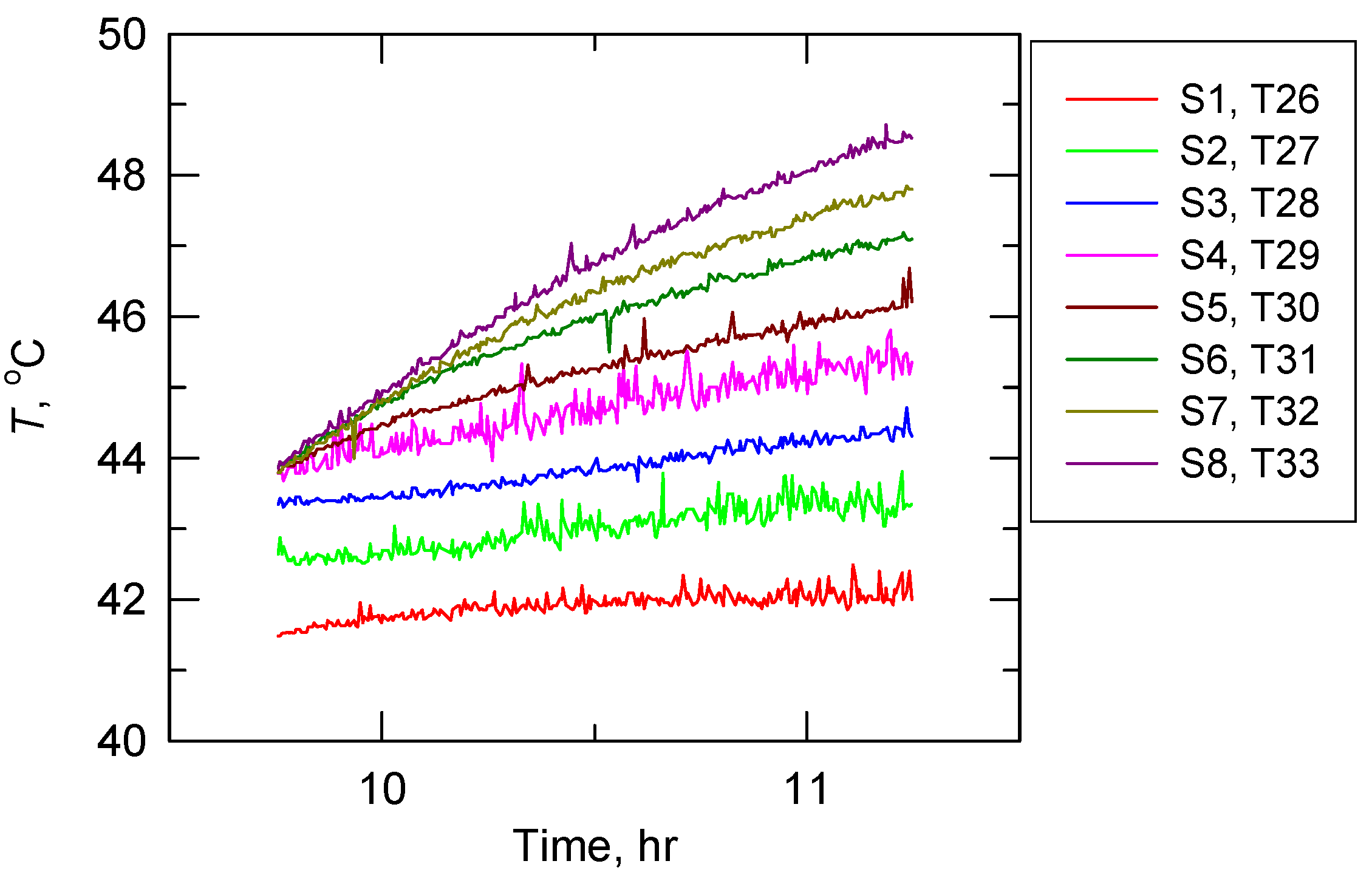
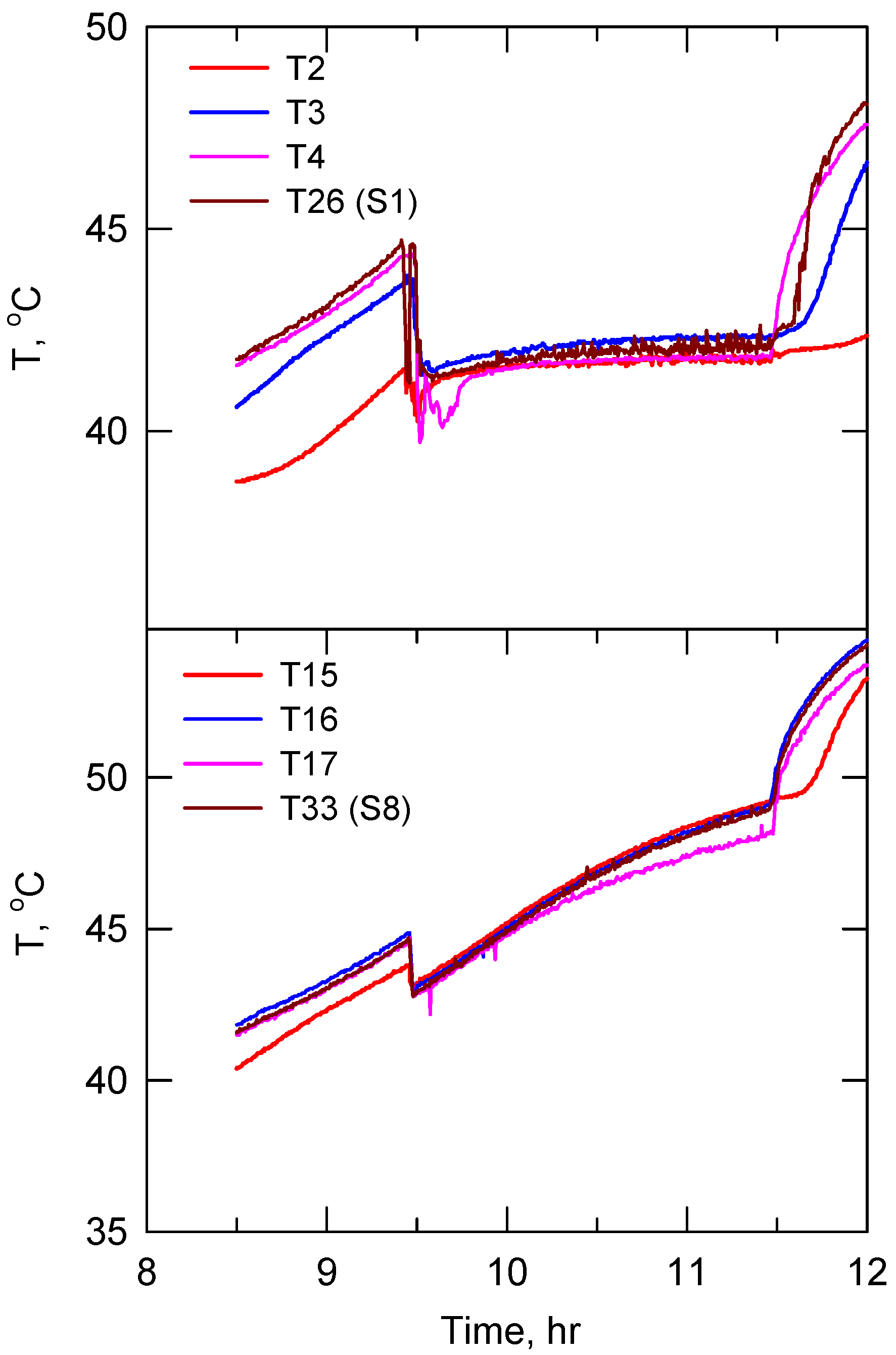
3.1. No-Load and Intermittent Load Cases

For a thermosyphon SWH, the level of temperature stratification inside a tank has a direct influence on the thermal performance of the system. It is also well known that thermosyphon flow rates m ˙ t h e r depend on solar radiation intensity. The variation of m ˙ t h e r (S4) with I during the mid-part of the operation period for the no-load case is shown in Figure 4. Note that the I ranged from 500 to 900 W/m2 under the present test conditions. Although the data were a little scattered at lower I, there was a large variation in m ˙ t h e r (0.015 to 0.035 kg/s) because of variation in the I. Higher m ˙ t h e r would cause all the tank content to be circulated through the collector in a shorter period, resulting in higher inlet temperature.
Figure 4. Thermosyphon flow rate, no-load case.
Energies 05 03266 g004
As shown in Figure 3, temperature difference across the tank decreased toward the end of the operation period. The thermal driving forces were reduced, and all the water became nearly the same temperature, resulting in a lower m ˙ t h e r and temperature difference across the collector. Furthermore, the water temperature in the tank bottom would be higher than that at the inlet of the absorber plate. Thus, there would be no more useful energy gained by the system toward the end of the operation period. It is known that the thermal efficiency of a SWH is associated with the pattern of hot water consumption. In this study, hot water was removed from the tank to simulate different applications. The thermal performance under the intermittent load conditions is given in Figure 5. The load was taken from the tank at intervals of two hours for DP-I and of one hour for DP-II. It can be seen that the thermal efficiency η for the DP-II case (η = 0.52) is slightly higher than that of the DP-I case (η = 0.51). When a single water withdrawal of 750 L was performed during the period of 15:30 to 18:00 (DP-III), η is roughly the same as that of the DP-I case. Further, the thermal performance for the no-load case (η = 0.48) was also shown in Figure 5. As mentioned above, the rate of useful energy transferred dropped toward the end of the operation period. The thermal efficiency for the intermittent load conditions was about 5.8 to 7.0% higher than the value for the no-load condition.
Figure 5. Thermal efficiency, no-load and intermittent load cases.
Energies 05 03266 g005

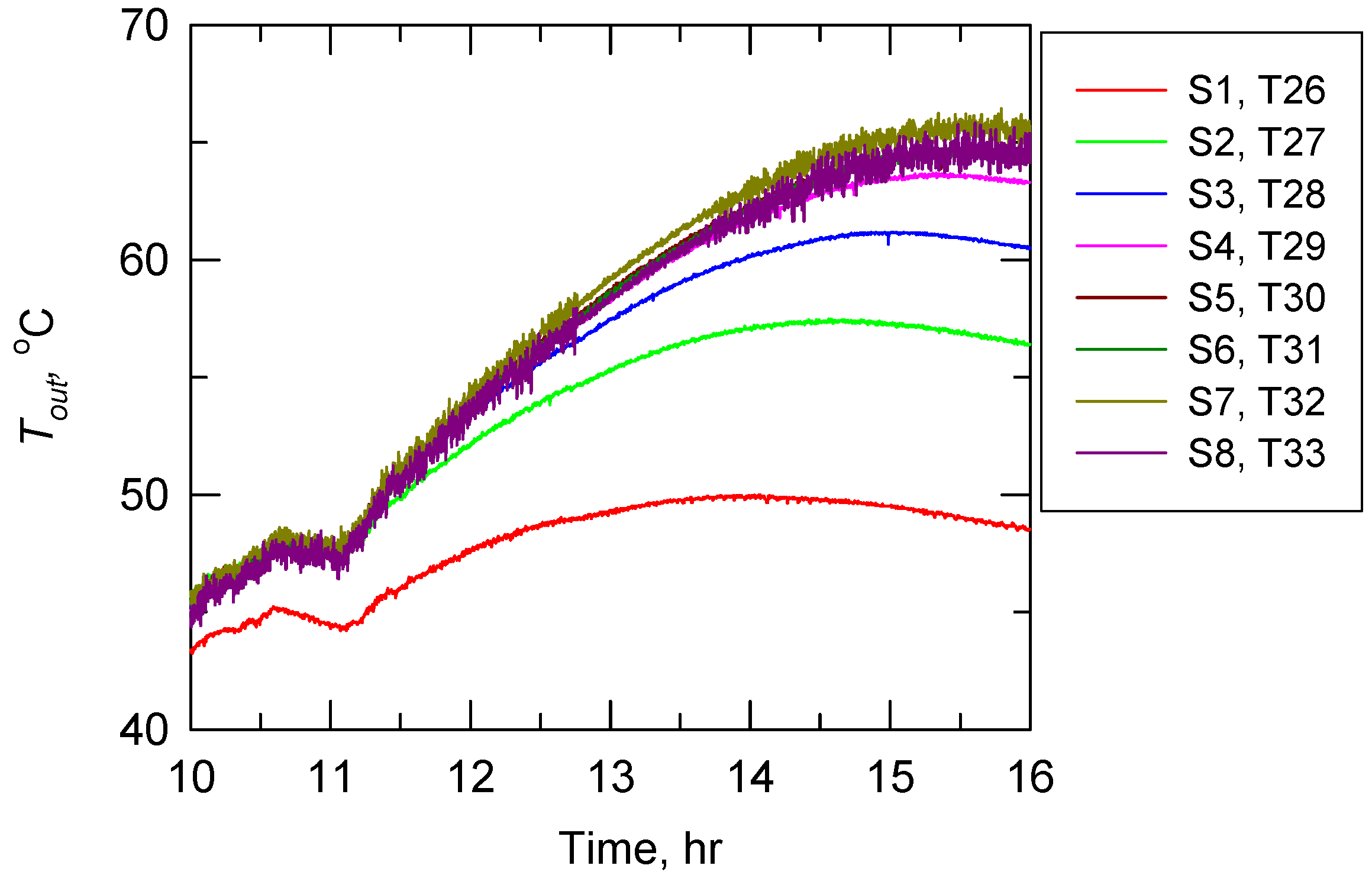
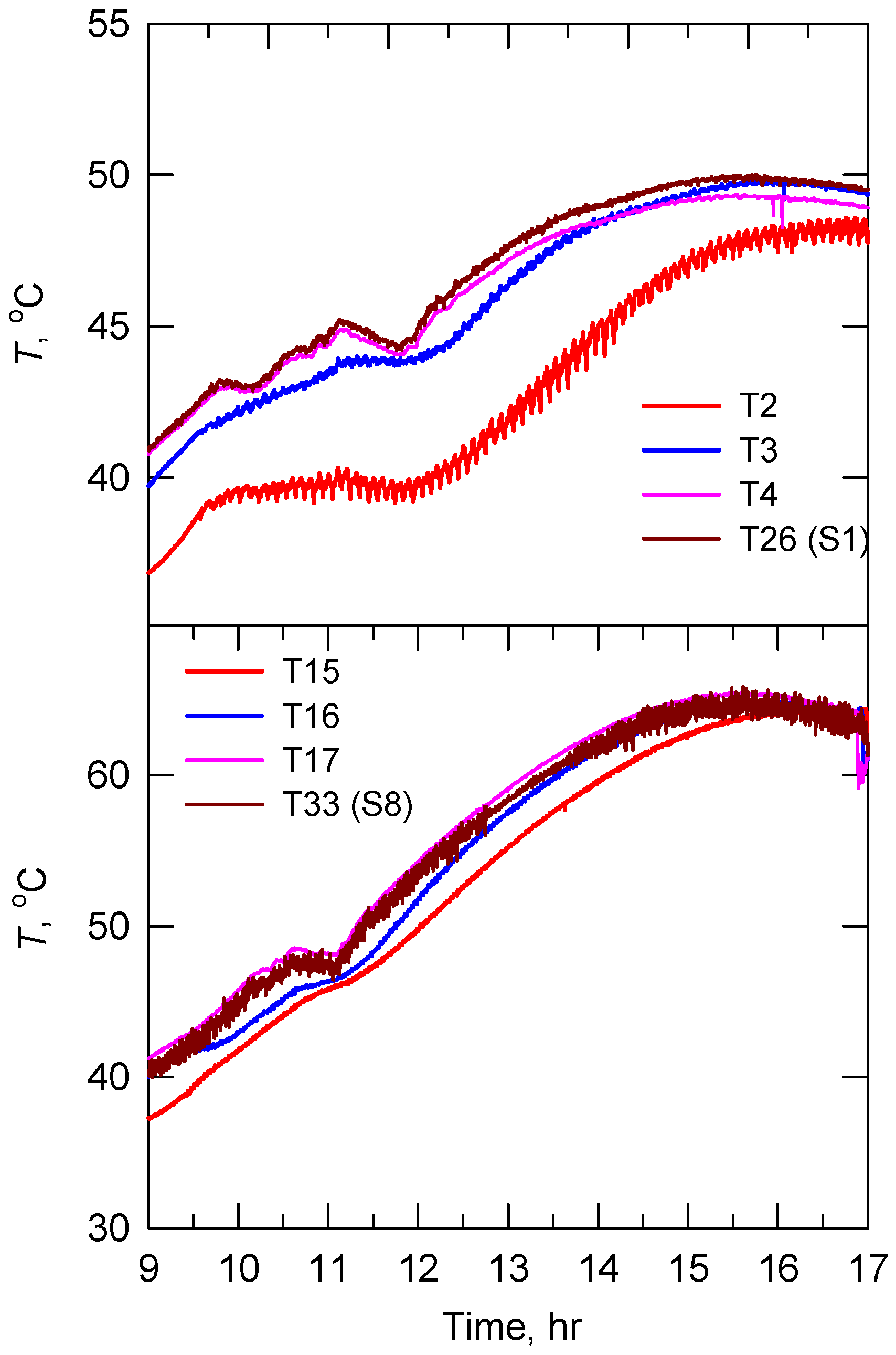
3.2. Continuous Load

A greater mixing effect is to be expected with water extracted from the tank of a thermosyphon SWH. However, the temperature stratification in the tank could be maintained at a low collector flow rate [14]. As mentioned above, m ˙ t h e r ranged from 0.015 (0.9 LPM) to 0.035 kg/s (2.1 LPM) with I = 500–800 W/m2. For the 0.8 LPM case, the flow rate is less than that of thermosyphon flow rate. An example of variation in the outlet temperature of all tanks is shown in Figure 6. It can be seen that the outlet temperature difference between the tanks of S1 and S2 started at a smaller value (1.3 °C) and gradually increased until about 15:00 (7.8 °C). Then the temperature difference between S2–S3 and S3–S4 declined. For the downstream SWHs (S4 to S8), the outlet temperature of the tanks varied less than 2 °C during the operating period. This implies that there might be no advantage to having more than 4 thermosyphon SWHs in series at lower flow rate. In addition, Figure 7 shows temperature variation in the tanks of S1 and S8, which were initially stratified tanks without load before 10:00. During the operating period, the measured temperatures at the bottom (T2, T15), middle (T3, T16) and top (T4, T17) of the tanks can be clearly distinguished, particularly for the S1. This indicates that the temperature stratification was well preserved at a flow rate less than m ˙ t h e r .
Figure 6. Outlet temperature variation of SWHs, 0.8 LPM case.
Energies 05 03266 g006
For the 10 LPM case, the flow rate is sufficiently higher than that of the thermosyphon flow rate. Under the load condition, the measured outlet temperatures of each tank gradually rose during the operation period, as shown in Figure 8. The rise in temperature across the tanks gradually declined and varied by less than 1 °C, indicating that the thermal performance of each SWH might be roughly the same at high flow rate. Furthermore, the temperature stratification in the tanks is of interest. As shown in Figure 9, stratification in tanks S1 and S8 can be observed when no water was drawn off from the system. During consumption of hot water from these tanks (9:45–11:25), degradation of the initially established temperature stratification can be seen and fully mixed tanks were presented. After the withdrawed period, significant temperature stratification redeveloped within half an hour. This would partially explain why thermal efficiency for the intermittent load cases was roughly the same.
Figure 7. Temperature variation in the tanks 1 and 8, 0.8 LPM case.
Energies 05 03266 g007
Figure 8. Outlet temperature variation of SWHs, 10 LPM case.
Energies 05 03266 g008
The thermal efficiency of thermosyphon SWHs under continuous load conditions can be presented in terms of output and accumulated energiesin each SWH, as shown in Figure 10 and Figure 11. At lower flow rates (0.8 and 1.7 LPM), the output energy reached the maxima at S1 and then there was a sharp decrease in discharging efficiency η1 at S2 and S3. It is also seen that η1 is less than 0.1 at S4, which indicates a small temperature difference between the inlet temperature of the collector and the outlet temperature of the tank. There was no useful energy transferred to the water by a system comprising more than 4 thermosyphon SWHs. At higher flow rates (5 and 10 LPM), cold water was injected further into the tank, resulting in a decrease in the mean temperature. In addition, η1 reached the maximum at S2 due to lower heat losses caused by lower operating temperature, and then gradually declined. Note that the maximum theoretical discharging efficiency could reach 100% [25]. The amount of accumulated energy in the tanks was obtained by multiplying the difference between the average temperatures of the water collected in the tanks and of the water at entry to the collector. At lower flow rates (0.8 and 1.7 LPM), there was an increase in η2 (or higher mean tank temperature) from S1 to S4. The overall efficiency at S4–S8 (η1 + η2 ≈ 0.49) was roughly the same. At higher flow rates (5 and 10 LPM), the temperature difference across the collector and tank was flatter at S1–S3 and increased from S4 to S8. The overall efficiency at S4–S8 (≈ 0.60) was higher than that at lower flow rates.
Figure 9. Temperature variation in the tanks 1 and 8, 10 LPM case.
Energies 05 03266 g009
Figure 10. Output energy of SWHs, continuous load conditions.
Energies 05 03266 g010
Figure 11. Accumulated energy of SWHs, continuous load conditions.
Energies 05 03266 g011

4. Conclusions

Eight thermosyphon SWHs in series were instrumented to measure the thermal performance and temperature profiles under specified charge conditions. The measured results point to a number of observations as follows:
  • After a water draw-off period, the tank water would redistribute itself and temperature stratification was redeveloped within a short period under intermittent load conditions.
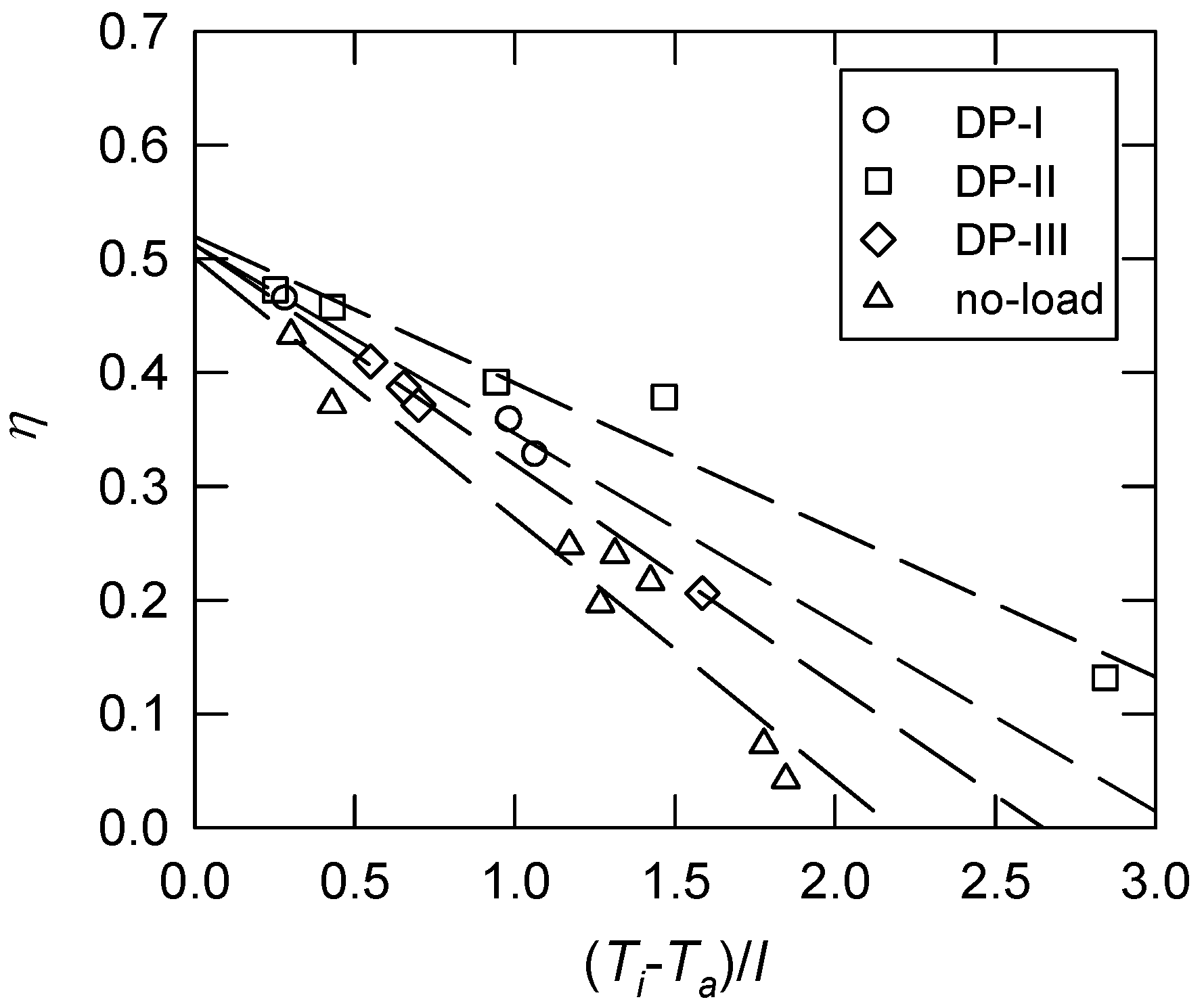
  • The thermal efficiency for intermittent load conditions is about 5.8% to 7.0% higher than the value for the no-load condition.
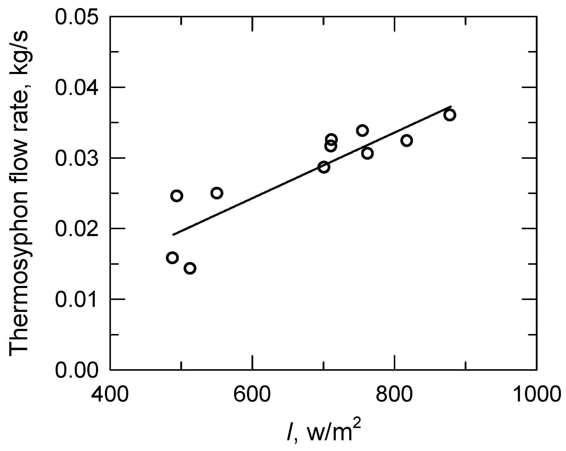
  • Under continuous load conditions, the temperature stratification in tanks is only preserved at flow rates less than the thermosyphon flow rate. The discharge efficiency decreases significantly for systems comprised of more than four thermosyphon SWHs, and there is no useful energy transferred to the water.The overall efficiency increases with an increase in the flow rate. Thermosyphon SWHs show more dependence on water draw-off profiles than temperature stratification in tanks. In addition, a series-parallel combination of thermosyphon SWHs would have a good performance for industrial applications.

Acknowledgments

The study is under the support of Bureau of Energy, Ministry of Economic Affairs, Republic of China.

References

  1. Weiss, W.; Bergmann, I.; Faninger, G. Solar Heat Worldwide: Markets and Contribution to the Energy Supply 2009 (Edition 2011); Institute for Sustainable Technologies: Gleisdorf, Austria, May 2011. [Google Scholar]
  2. Roulleau, T.; Lloyd, C.R. International policy issues regarding solar water heating, with a focus on New Zealand. Energy Policy 2008, 36, 1843–1857. [Google Scholar] [CrossRef]
  3. Karagiorgas, M.; Botzios, A.; Tsoutsos, T. Industrial solar thermal applications in Greece economic evaluation, quality requirements and case studies. Renew. Sustain. Energy Rev. 2001, 5, 157–173. [Google Scholar] [CrossRef]
  4. Chang, K.C.; Lee, T.S.; Chung, K.M. Solar water heaters in Taiwan. Renew. Energy 2006, 31, 1299–1308. [Google Scholar] [CrossRef]
  5. Li, Z.S.; Zhang, G.Q.; Li, D.M.; Zhou, J.; Li, L.J.; Li, L.X. Application and development of solar energy in building industry and its prospects in China. Energy Policy 2007, 35, 4121–4127. [Google Scholar] [CrossRef]
  6. Chang, K.C.; Lee, T.S.; Lin, W.M.; Chung, K.M. Outlook for solar water heaters in Taiwan. Energy Policy 2008, 36, 66–72. [Google Scholar] [CrossRef]
  7. Chang, K.C.; Lin, W.M.; Ross, G.; Chung, K.M. Dissemination of solar water heaters in South Africa. J. Energy South. Afr. 2011, 22, 2–7. [Google Scholar]
  8. Zago, M.; Casalegno, A.; Marchesi, R.; Rinaldi, F. Efficiency analysis of independent and centralized heating systems for residential buildings in Northern Italy. Energies 2011, 4, 2115–2131. [Google Scholar] [CrossRef]
  9. Duffie, J.A.; Beckman, W.A. Solar Engineering of Thermal Processes; John Wiley Sons: Hoboken, NJ, USA, 1980; Chapter 12; pp. 487–497. [Google Scholar]
  10. Prapas, D.E.; Veliannis, I.; Evangelopoulos, A.; Sotiropoulos, B.A. Large DHW solar systems with distributed storage tanks. Sol. Energy 1995, 35, 175–184. [Google Scholar] [CrossRef]
  11. Chang, K.C.; Lin, W.M.; Lee, T.S.; Chung, K.M. Local market of solar water heaters in Taiwan: Review and perspectives. Renew. Sustain. Energy Rev. 2009, 13, 2605–2612. [Google Scholar] [CrossRef]
  12. Lin, W.M.; Chang, K.C.; Liu, Y.M.; Chung, K.M. Field surveys of non-residential solar water heating systems in Taiwan. Energies 2012, 5, 258–269. [Google Scholar] [CrossRef]
  13. Garg, H.P. Design and performance of a large-size solar water heater. Sol. Energy 1973, 14, 303–312. [Google Scholar] [CrossRef]
  14. Shitzer, A.; Kalmanoviz, Y.; Zvirin, Y.; Grossman, G. Experiments with a flat plate solar water heating system in thermosyphonic flow. Sol. Energy 1978, 22, 27–33. [Google Scholar] [CrossRef]
  15. Mishra, R.S. Theoretical and experimental studies of pressurized and non-pressurized solar water heating systems of thermosyphonic type. Renew. Energy 1992, 2, 371–384. [Google Scholar] [CrossRef]
  16. Shariah, A.M.; Lof, G.O.G. The optimization of tank-volume-to-collector-area ratio for a thermosyphon solar water heater. Renew. Energy 1996, 7, 289–300. [Google Scholar] [CrossRef]
  17. Karaghouli, A.A.; Alnaser, W.E. Experimental study on thermosyphon solar water heater in Bahrain. Renew. Energy 2001, 24, 389–396. [Google Scholar] [CrossRef]
  18. Belessiotis, V.; Mathioulakis, E. Analytical approach of thermosyphon solar domestic hot water system performance. Sol. Energy 2002, 72, 307–315. [Google Scholar] [CrossRef]
  19. Michaelides, I.; Eleftheriou, P.; Siamas, G.A.; Roditis, G.; Kyriacou, P. Experimental investigation of the night losses of hot water storage tanks in thermosyphon solar water heaters. J. Renew. Sustain. Energy 2011, 3, 033103:1–033103:9. [Google Scholar] [CrossRef]
  20. Young, M.F.; Berguam, J.B. The performance of a thermosyphon solar domestic hot water system with hot water removal. Sol. Energy 1984, 32, 655–658. [Google Scholar] [CrossRef]
  21. Young, M.F.; Bauhn, J.W. An investigation of thermal stratification in horizontal storage tanks. ASME J. Sol. Energy Eng. 1981, 103, 286–290. [Google Scholar] [CrossRef]
  22. Jannatabadi, M.; Taherian, H. An experimental study of influence of hot water consumption rate on the thermal stratification inside a horizontal mantle storage tank. Heat Mass Transf. 2012. [Google Scholar] [CrossRef]
  23. Prapas, D.E.; Veliannis, I.; Evangelopoulos, A.; Sotiropoulos, B.A. Beneficial interconnection of two thermosyphon DHW solar systems. Appl. Energy 1994, 49, 47–60. [Google Scholar] [CrossRef]
  24. Morrison, G.L.; Braun, J.E. System modelling and operation characteristics of thermosyphon solar water heaters. Sol. Energy 1985, 34, 389–405. [Google Scholar] [CrossRef]
  25. Sezai, I.; Aldabbagh, L.B.Y.; Atikol, U.; Hacisevki, H. Performance improvement by using dual heaters in a storage-type domestic electric water heater. Appl. Energy 2005, 81, 291–305. [Google Scholar] [CrossRef]

